Article

Comparative Study on Microstructure and Mechanical Properties of Fusion Zones in X65/Ni825 Bimetallic Pipe Welds with Different Filler Metals

1
Shandong Key Laboratory of Intelligent Energy Materials, School of Materials Science and Engineering, China University of Petroleum (East China), Qingdao 266580, China
2
China Petroleum Engineering & Construction Corp. North China Company, Renqiu 062550, China
*
Author to whom correspondence should be addressed.
Metals 2026, 16(7), 764; https://doi.org/10.3390/met16070764
Submission received: 10 June 2026 / Revised: 3 July 2026 / Accepted: 7 July 2026 / Published: 9 July 2026

Abstract

X65/Ni825 bimetallic composite pipes combine the load-bearing capacity of pipeline steel with the corrosion resistance of nickel-based alloys, making them promising candidates for harsh oil and gas transportation environments. However, their welded joints usually exhibit significant microstructural and compositional heterogeneities, especially in fusion zones and interpass transition regions, which can strongly affect local mechanical properties. In this study, X65/Ni825 bimetallic composite pipe welded joints were investigated, and the microstructure, elemental transition behavior, microhardness, and local mechanical properties of different weld passes and fusion zones in full high-alloy filler metal welded joints and hybrid filler metal welded joints were compared. The results show that all weld passes in the full high-alloy filler metal welded joint are mainly composed of γ-Ni cellular/columnar dendrites, showing good microstructural and mechanical uniformity. In contrast, the hybrid filler metal welded joint exhibits obvious microstructural passing. A compositional transition zone is formed between the transition and filler passes due to local remelting, dilution, and metallurgical mixing, accompanied by sharp changes in hardness and local strength. Overall, the full high-alloy filler metal system is more effective in reducing microstructural, compositional, and mechanical discontinuities within the weld, providing guidance for welding process optimization of X65/Ni825 bimetallic composite pipes.

1. Introduction

As oil and gas development moves toward harsher environments with high H2S, CO2, Cl, temperature, and pressure, conventional carbon steel pipelines are increasingly limited by poor corrosion resistance. In contrast, solid corrosion-resistant alloy pipes are difficult to apply on a large scale because of their high cost [1,2]. Therefore, bimetallic composite pipes, as a new type of petroleum pipeline structure, have become promising materials for sour oil and gas transportation, offshore pipelines, and complex media transport. In this pipe structure, the outer carbon steel pass provides mechanical strength and pressure resistance, while the inner corrosion-resistant alloy pass provides corrosion protection [3].
Bimetallic composites have been extensively investigated in various engineering fields, including steel–copper, aluminum–copper, and pipeline steel–nickel alloy systems, with particular emphasis on their bonding mechanisms, interfacial characteristics, and mechanical properties [4,5,6]. In the context of oil and gas pipelines, bimetallic composite pipes made of pipeline steels such as X65 or L415 and nickel-based corrosion-resistant alloys such as Alloy 825/Incoloy 825 (UNS N08825) can improve the corrosion resistance of the inner surface while maintaining sufficient load-bearing capacity, showing high engineering value [7,8,9]. However, during welding of composite pipes, the welded joint undergoes complex thermal cycles, melting and solidification, elemental dilution, and metallurgical mixing. These processes lead to significant microstructural and compositional heterogeneity in the joint region. In particular, clear composition gradients and local property differences often exist at the fusion zone between the weld metal and X65 base metal, as well as at the interpass transition zones between weld passes deposited with different filler metals. These regions may become key locations affecting deformation compatibility and service reliability of the welded joint [10,11,12,13].
For welding X65/Ni825 bimetallic composite pipes, two filler metal systems are commonly used. One is the full high-alloy welding method, in which corrosion-resistant alloy (CRA) filler metals are used throughout the entire joint thickness. The other is the hybrid filler metal welding method, in which different filler metals are selected for different weld passes according to the characteristics of the backing steel and the cladding alloy [14,15]. The full high-alloy filler metal system is beneficial for maintaining compositional and microstructural uniformity in the weld metal, but it may involve higher filler metal cost and potential strength-matching issues [16,17]. In contrast, the hybrid filler metal system can better match the material requirements of different regions. However, a pronounced interpass compositional transition and abrupt changes in local mechanical properties may occur between the nickel-based weld pass and the steel-based weld pass [18]. Therefore, differences in microstructure, elemental transition, and local mechanical properties are critical for evaluating the metallurgical compatibility and structural reliability of these welded joints.
At present, most studies on bimetallic composite pipe welded joints have focused on overall mechanical properties, corrosion behavior, or macroscopic interfacial features [19,20,21,22,23]. In contrast, limited attention has been paid to the local microstructural differences, elemental transition behavior, and their influence on local mechanical properties in different weld passes and fusion zones under different filler metal systems. In particular, full high-alloy and hybrid filler metal welded joints may differ significantly in compositional continuity, interpass metallurgical mixing, fusion-zone microstructure, and local hardness and strength distribution, but the related mechanisms remain unclear.
Therefore, welded joints of X65/Ni825 bimetallic composite pipes were investigated in this study. The microstructure, elemental transition behavior, and local mechanical properties of different weld passes and fusion zones produced by full high-alloy filler metal welding and hybrid filler metal welding were systematically compared. By using optical microscope (OM), scanning electron microscope (SEM), energy-dispersive X-ray spectroscopy (EDS), mechanical property characterization, and numerical simulation, the effects of filler metal systems on weld metal passing, elemental gradient distribution, and local mechanical property variation were clarified. This study provides a basis for optimizing the welding process and evaluating the service reliability of X65/Ni825 bimetallic composite pipes.

2. Materials and Methods

2.1. Experimental Materials and Welding Procedures

An X65/Ni825 bimetallic composite pipe with a specification of φ813 × (22.23 + 2.5) mm was used in this study. The pipe had an outer diameter of 813 mm, with a 22.23 mm-thick X65 pipeline steel backing pass and a 2.5 mm-thick UNS N08825 nickel-based corrosion-resistant alloy liner. The chemical compositions of the two materials are given in Table 1 and Table 2.
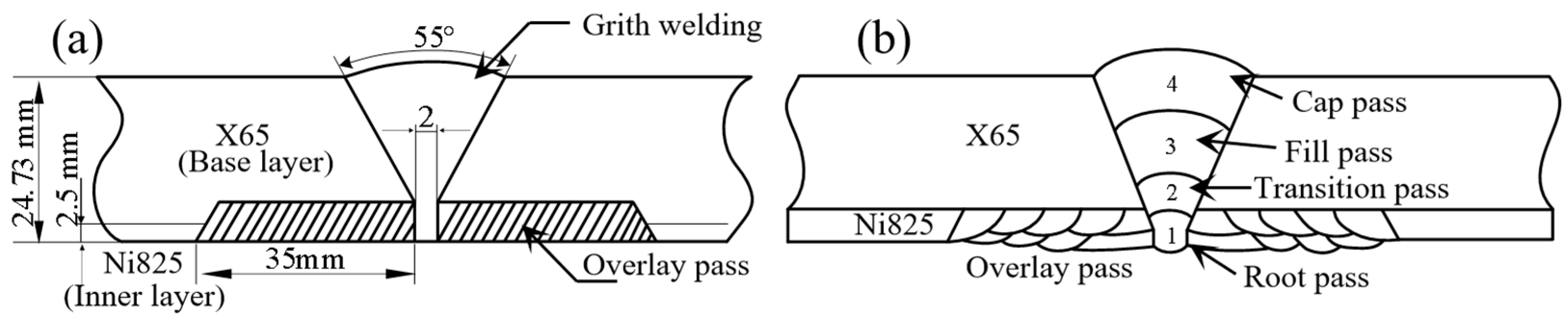
The groove design and welding sequence of the full high-alloy filler metal welded joint are shown in Figure 1a,b, respectively. The groove was designed with an angle α of 55°, a root gap of 2 mm, a root face of 3.5 mm, and an overlay length b of 35 mm at the pipe end. To prevent direct metallurgical interaction between the X65 steel and the nickel-based weld metal, a 35 mm long ERNiCrMo-3 nickel-based overlay was applied to the pipe-end inner surface by Gas Tungsten Arc Welding (GTAW) prior to butt welding, as depicted in Figure 1a. After machining the groove geometry, the welding procedure adhered to a stringent interpass temperature limit of 100 °C. The butt weld consisted of four passes: root, transition, filler, and covering passes. The root and transition passes were also deposited by GTAW using ERNiCrMo-3 filler wire, while the filler and covering passes were deposited by Shielded Metal Arc Welding (SMAW) using a 3.2 mm diameter ERNiCrMo-3 nickel-based electrode. The welding parameters are listed in Table 3.
The hybrid filler metal welding process used the same groove design and welding sequence as the full high-alloy filler metal welding process. However, CHE507 carbon steel electrodes were selected for the filler and covering passes instead of ERNiCrMo-3 nickel-based filler metals. The CHE507 carbon steel electrode was used in the filler and covering passes primarily for cost reduction, as nickel-based filler metals are substantially more expensive. Despite its compositional mismatch with X65, CHE507 provides adequate strength for the upper weld passes where corrosion resistance is not required. In addition, its use together with the nickel-based root and transition passes enables a gradual compositional transition across the weld thickness. The welding parameters were selected to ensure sufficient dilution and metallurgical bonding at the interpass interface. The welding parameters are listed in Table 4.
For both welding procedures, pipe-end overlay welding was carried out before butt welding using ERNiCrMo-3 filler metal. In the full high-alloy filler metal welded joint, all weld passes were deposited with ERNiCrMo-3. In contrast, the hybrid filler metal welded joint was produced using ERNiCrMo-3 and CHE507 in different weld passes. The chemical compositions of the filler metals, as provided by the manufacturer’s certificate of analysis, are listed in Table 5.

2.2. Microstructural and Elemental Characterization

Microstructural characterization was performed using a OM (DM2500M/S6D, Leica, Wetzlar, Germany) and SEM (JSM-7200, JEOL, Akishima, Japan). Specimens containing the complete welded joint were prepared by wire electrical discharge machining, with a thickness of 10 mm. The specimens were ground, polished, and etched before observation. During etching, the carbon steel region was first etched using a 4% nitric acid alcohol solution, followed by etching of the corrosion-resistant alloy region using aqua regia. The corresponding microstructures were then observed separately. In addition, EDS (JSM-7200, JEOL, Japan) was used to analyze the chemical composition across the fusion zones and interpass transition regions, in order to investigate the elemental distribution and compositional transition behavior.

2.3. Mechanical Properties

Vickers hardness tests were carried out using a hardness tester (HVS-50, Aolong, Dandong, China) in accordance with GB/T 4340.1–2024 [24]. A test load of 9.8 N and a dwell time of 15 s were applied. The hardness distributions across different fusion zones of the two welded joints were measured, with a minimum spacing of 0.05 mm between adjacent indentations to ensure that the indentation size was smaller than the width of the fusion zone.
Instrumented indentation tests were conducted in accordance with GB/T 39635–2020 [25], Metallic materials—Instrumented indentation test for determining indentation tensile properties and residual stress. The tests were performed on different weld passes, heat-affected zones, and base metal regions of the two welded joints. A spherical tungsten carbide indenter with a diameter of 0.5 mm, a Poisson’s ratio of 0.23, and an elastic modulus of 710 GPa was used. The tests were conducted under displacement control at a loading rate of 0.2 mm/min to ensure quasi-static conditions. Before testing, a preload of 5 N was applied to the specimen surface. Continuous loading–partial unloading cycles were then carried out at equal intervals, with eight loading–unloading cycles in total. In each cycle, the unloading load was reduced to 50% of the maximum load of the current cycle. The indentation load–depth curves were finally obtained.

2.4. Finite Element Modeling

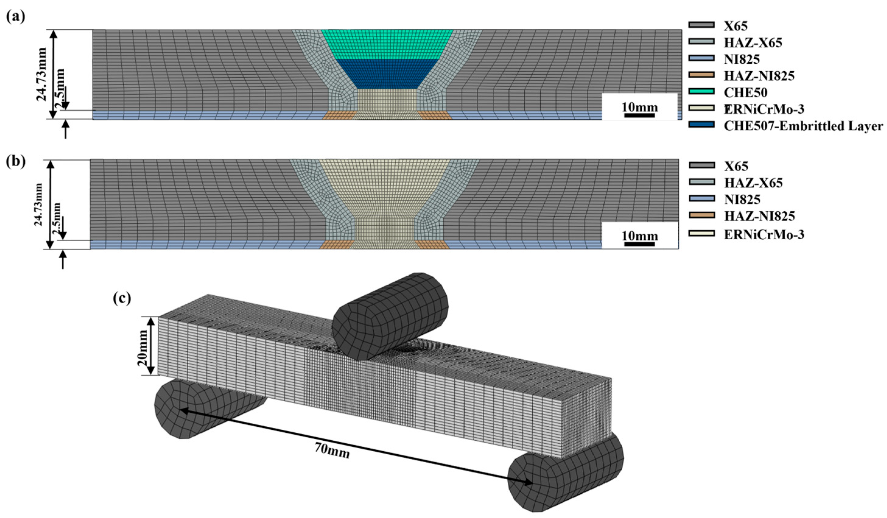
To further investigate the effect of different welding procedures on the mechanical behavior of the welded joints, finite element simulation of the three-point bending process was performed using ABAQUS 2024. The model was established based on the actual weld geometry and dimensions of the composite pipe joint. C3D8R elements were mainly used for meshing, with a limited number of C3D4 elements introduced in transition regions to reduce the computational cost. To improve simulation accuracy while maintaining computational efficiency, mesh refinement was applied to the weld region and the adjacent fusion zones, with a minimum element size of approximately 0.2 mm, whereas coarser meshes were used in regions far from the weld. Furthermore, the material properties of the different weld regions used in the numerical simulations were defined using the true stress–strain curves derived from the instrumented indentation tests.
An adaptive time-integration strategy based on the minimum stable time increment was used to improve computational efficiency while maintaining accuracy. The weld reinforcement was removed from the model to prevent irregular element compression during bending and to improve numerical convergence, as shown in Figure 2a. The weld metal region is distinguished by different colors for different weld passes. From bottom to top, they correspond to the root pass, transition pass, filler pass, and root pass, respectively. In addition, the mesh in the heat-affected zone has been refined.
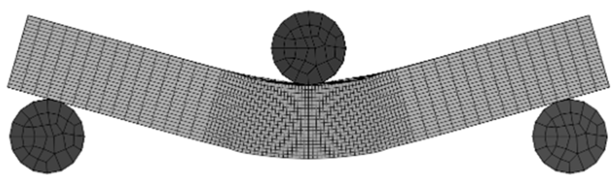
To simulate the side-bending condition, contact interactions were defined between the lower surface of the specimen and the support rollers. A displacement load in the negative Z-direction was applied to the reference point (RP) of the loading punch to induce bending deformation of the welded joint. This model was used to analyze the stress distribution and damage evolution during bending, as shown in Figure 2b.

3. Results and Discussion

3.1. Microstructural Characteristics of Different Weld Passes

3.1.1. Hybrid Filler Metal Welded Joint

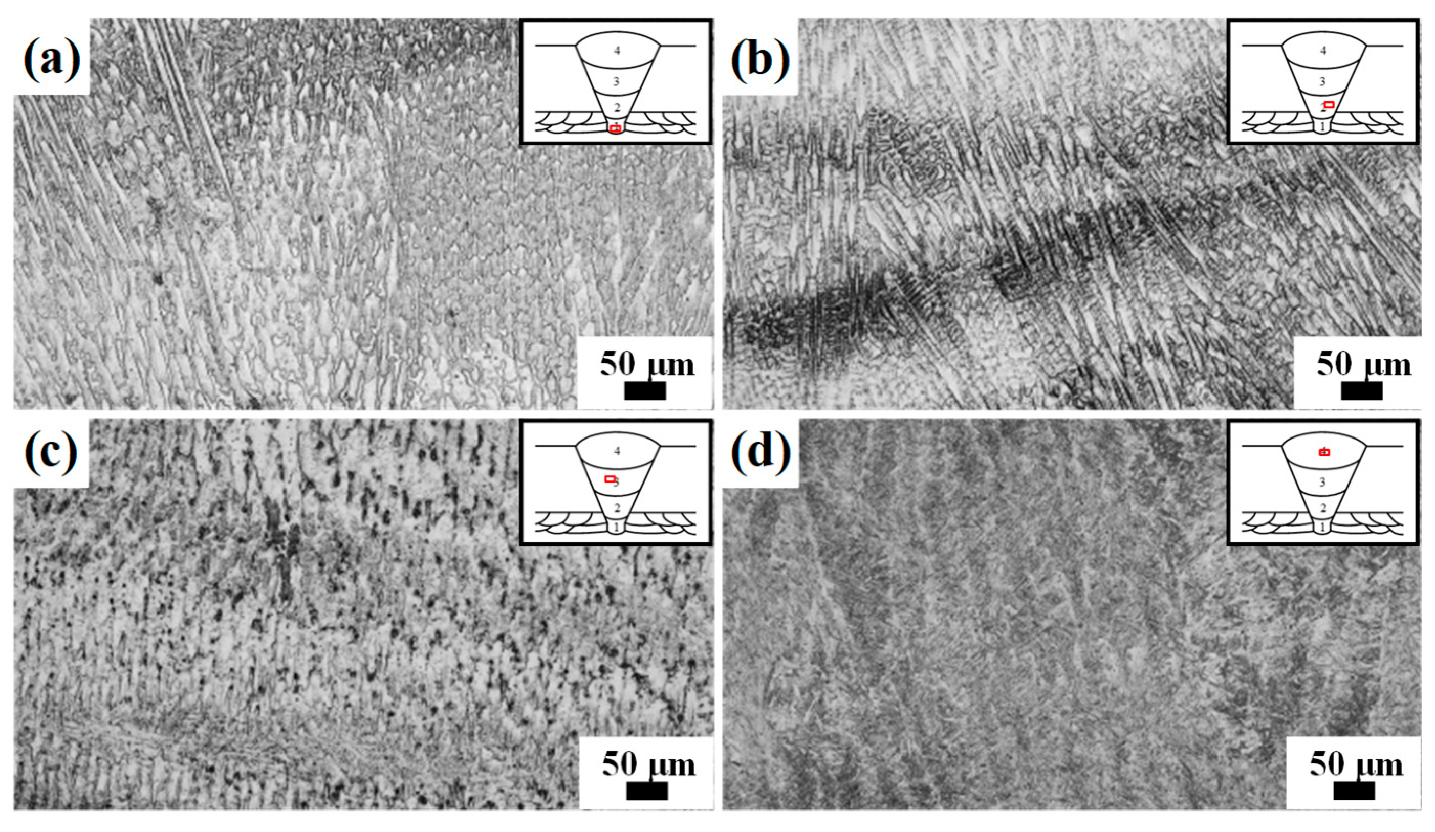
Figure 3 shows the metallographic microstructures of different weld passes in the hybrid filler metal welded joint (The area highlighted by the red box is the test area. According to the welding procedure, ERNiCrMo-3 nickel-based filler metal was used for the root and transition passes, whereas CHE507 carbon steel electrodes were used for the filler and covering passes. As a result, the different weld passes exhibit a distinct passed microstructural feature.
The root pass (Figure 3a) shows a clear directional solidification feature. Its microstructure is mainly composed of γ-Ni cellular dendrites and columnar dendrites growing along the heat flow direction. The primary dendrite arms are clearly visible and highly directional. Elemental segregation may also occur in the interdendritic regions due to solute redistribution during solidification. Since the root pass is adjacent to the fusion line and the base metal interface, its solidification process is jointly affected by a high temperature gradient and dilution from the base metal. Therefore, this pass can be regarded as a typical nickel-based weld solidification microstructure. The transition passes (Figure 3b) are still mainly composed of γ-Ni cellular and columnar dendrites, indicating that this region basically retains the main morphological features of a nickel-based weld solidification microstructure. Compared with the root pass, the transition pass exhibits a more complex dendrite orientation, with more clearly defined interdendritic regions and slightly reduced microstructural uniformity. This suggests that, after initial solidification, this region may have been further affected by the heat input from subsequent weld passes, making the microstructural and compositional differences in the interdendritic regions more pronounced. The microstructure of the filler pass (Figure 3c) is clearly different from that of the root and transition passes. The typical nickel-based dendritic solidification morphology is no longer dominant in this region. Instead, the microstructure mainly exhibits steel-based ferritic transformation characteristics. The covering pass (Figure 3d) exhibits a finer, more uniform, and denser microstructure. Clear long columnar primary dendrite arms are hardly observed, and the microstructure is mainly characterized by a relatively homogeneous refined morphology. Based on the observed morphology, this region is mainly characterized by refined acicular ferrite-like and granular transformation products. Compared with the filler pass, the covering pass exhibits improved microstructural uniformity. This feature is likely associated with its proximity to the weld surface, resulting in a relatively higher cooling rate, as well as the absence of subsequent thermal cycling from additional weld passes.
Overall, the hybrid filler metal welded joint shows a pronounced passed microstructural evolution across different weld passes. The lower root and transition passes mainly consist of γ-Ni cellular and columnar dendritic solidification microstructures, while the upper filler and covering passes are dominated by ferritic transformation microstructures. Such microstructural passing is expected to influence the elemental transition behavior and local mechanical properties of the corresponding fusion zones.

3.1.2. Full High-Alloy Filler Metal Welded Joint

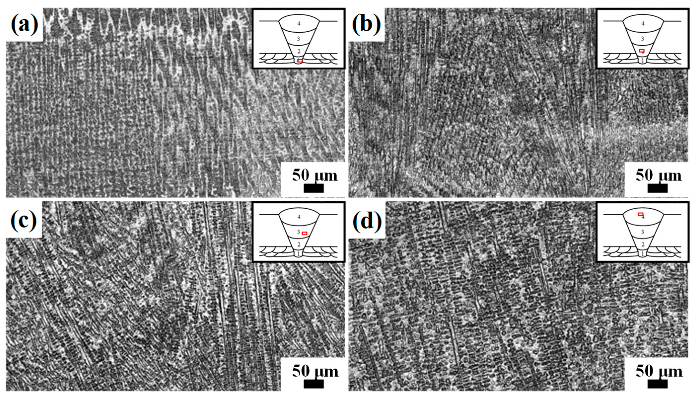
Figure 4 shows the metallographic microstructures of different weld passes in the full high-alloy filler metal welded joint (The area highlighted by the red box is the test area). As shown in the figure, all weld passes exhibit clear directional solidification characteristics, with microstructures mainly composed of cellular and columnar dendrites. However, certain differences in dendrite size, growth orientation, and interdendritic morphology can still be observed among different weld passes.
The root pass (Figure 4a) is mainly characterized by strongly oriented columnar dendrites with clearly visible primary dendrite arms. This indicates that pronounced directional growth occurred in this region under a relatively high temperature gradient and heat dissipation through the base metal interface. In addition, because the root pass is adjacent to the base metal and the cladding interface, its solidification process is also affected by a certain degree of dilution, resulting in more obvious microstructural heterogeneity. The transition pass (Figure 4b) is still dominated by dendritic microstructures. However, the dendrite orientation becomes more complex with locally intersecting growth features. This indicates that the region was further affected by subsequent weld thermal cycles after initial solidification. Secondary dendrite growth or local remelting may therefore have occurred, resulting in reduced microstructural uniformity. The filler pass (Figure 4c) shows well-developed columnar and cellular dendrites. The primary dendrite arms are clear and highly oriented, indicating typical nickel-based weld solidification characteristics. This suggests a relatively stable heat flow during solidification, which promoted continuous dendrite growth along the weld direction. In contrast, the covering pass (Figure 4d) exhibits a relatively refined microstructure. It is mainly composed of dense cellular dendrites and short columnar dendrites. The primary dendrite arms become shorter, resulting in a more compact microstructure. This refinement is mainly related to the location of the covering pass near the weld surface and the corresponding higher cooling rate. As the final weld pass, the covering pass was not affected by subsequent thermal cycles. Therefore, its microstructure is closer to the original morphology retained after final solidification.
For ERNiCrMo-3 weld metal, the matrix is generally composed of γ-Ni solid-solution dendrites. Nb and Mo may segregate to the interdendritic regions during solidification. Therefore, the morphological differences in the interdendritic regions among different weld passes are likely related to solidification segregation. Overall, the differences in solidification conditions and thermal cycles during multi-pass welding are the main reasons for the heterogeneous microstructural evolution in the full high-alloy filler metal welded joint.
Overall, the full high-alloy filler metal welded joint maintains relatively consistent directional solidification characteristics of a nickel-based weld metal across all weld passes. The microstructural differences are mainly reflected in variations in dendrite size, growth orientation, and interdendritic morphology. In contrast, the hybrid filler metal welded joint shows more pronounced microstructural passing along the thickness direction. The lower weld passes retain nickel-based dendritic solidification microstructures, whereas the upper weld passes gradually transform into ferritic and granular bainitic microstructures. This indicates that different filler metal systems not only alter the solidification behavior of the weld metal but also significantly increase the microstructural heterogeneity within the joint. Such heterogeneity is expected to have an important effect on the elemental transition behavior and mechanical properties of the subsequent fusion zones.

3.2. Elemental Distribution and Transition Behavior of Fusion Zones

3.2.1. Hybrid Filler Metal Welded Joint

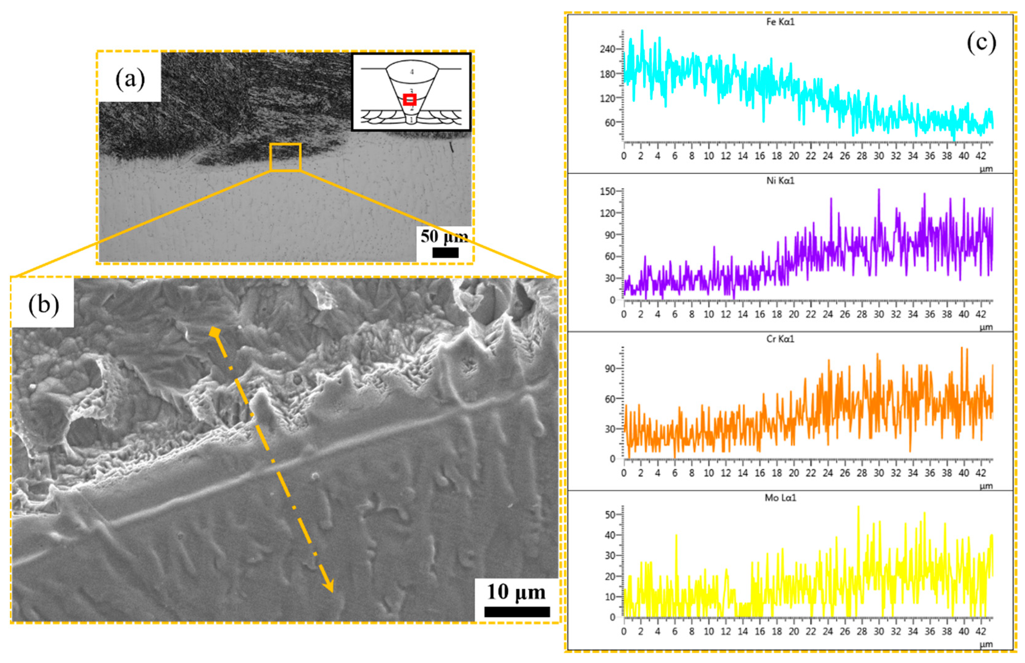
Figure 5 shows the SEM morphology and EDS line-scan results across the interface between the transition pass and the filler pass in the hybrid filler metal welded joint. As the scanning path extends from the transition pass to the filler pass, the Fe content gradually increases, whereas the Ni, Cr, and Mo contents decrease. This indicates the formation of a distinct compositional transition zone between the two weld metal passes. During filler-pass welding, the arc heat input can cause local remelting of the underlying nickel-based transition pass. The remelted nickel-based weld metal then undergoes dilution and metallurgical mixing with the Fe-based molten pool, resulting in a continuous compositional gradient with increasing Fe content and decreasing Ni, Cr, and Mo contents. From the perspective of compositional characteristics, this transition zone provides favorable conditions for the formation of locally hardened microstructures. In particular, on the side close to the filler pass, the Fe content increases markedly, while a certain amount of Ni, Cr, and Mo is still retained. This compositional feature may increase the hardenability of the local steel-based microstructure and promote the formation of locally hardened transformation products, such as low-temperature transformation products (e.g., acicular ferrite and/or martensite-austenite (M/A) constituents), under rapid weld cooling conditions.

3.2.2. Full High-Alloy Filler Metal Welded Joint

Figure 6 shows the metallographic microstructures of the fusion zones between different weld passes and the base metal in the full high-alloy filler metal welded joint. It can be seen that the heat-affected zones on the X65 side of the fusion zones exhibit clear microstructural differences among different weld passes. Among these regions, the steel side near the transition pass (Figure 6a) mainly exhibits typical coarse-grained heat-affected zone (CGHAZ) characteristics. The heat-affected zone near the filler pass (Figure 6b) shows the most pronounced coarsening, with locally coarser transformation microstructures. In contrast, the heat-affected zone near the covering pass (Figure 6c) is relatively refined and more uniform. These differences are mainly related to variations in peak temperature, heat accumulation, the number of subsequent reheating cycles, and cooling conditions at different weld-pass positions.
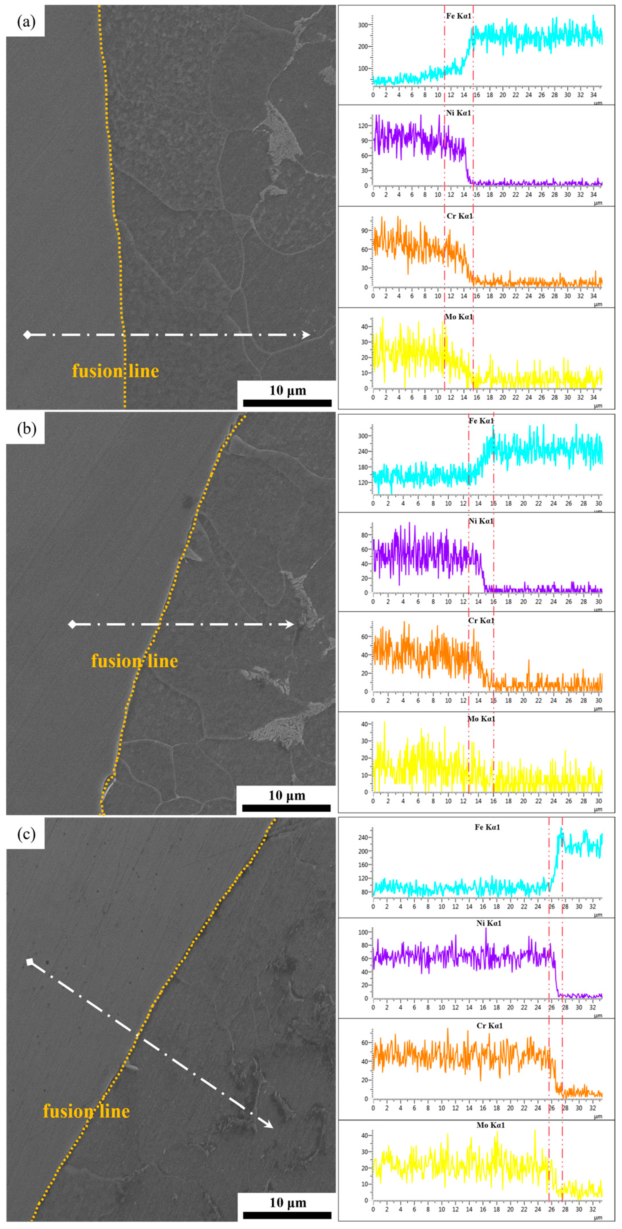
Figure 7 presents the EDS line-scan results across the fusion zones between different weld passes and the X65 base metal in the full high-alloy filler metal welded joint. Figure 7a–c correspond to the fusion zones between the base metal and the transition pass, filler pass, and covering pass, respectively. The three fusion zones all exhibit a pronounced compositional transition. As the scanning path moves from the weld metal side to the X65 base metal side, the Fe content increases sharply, while the Ni, Cr, and Mo contents decrease rapidly. This indicates the presence of a compositional transition zone between the weld metal and the base metal. For bimetallic composite pipe joints, the compositional variation near the fusion line mainly results from weld melting, base metal dilution, and subsequent solidification after local metallurgical mixing. It should not be regarded as a wide solid-state diffusion pass. Therefore, the compositional transition shown in the figure essentially reflects elemental redistribution within the local mixing zone near the fusion line. It is worth noting that the three fusion zones exhibit different transition behaviors. This indicates that although the same filler metal system was used in all weld passes of the full high-alloy joint, the local dilution degree and thermal history varied with weld-pass position.
For the fusion zone between the transition pass and the base metal (Figure 7a), the compositional variation is relatively gradual. The Fe content on the weld metal side begins to increase before reaching the fusion line, while the decrease in Ni, Cr, and Mo is also less abrupt. This indicates a relatively wider transition zone in this region. Based on the preceding microstructural observations of the fusion zones, the steel side adjacent to the fusion line in the transition pass/base metal fusion zone mainly exhibits typical coarse-grained heat-affected zone characteristics. Its dominant feature is the formation of coarse transformation microstructures resulting from prior austenite grain growth. In addition, this region was subsequently subjected to the thermal input from the filler and covering passes. As a result, the compositional transition zone near the fusion line may have been widened by repeated reheating. Thus, the transition pass fusion zone shows a relatively wide and gradual compositional transition. This behavior is associated with the stronger reheating effect from subsequent weld passes. In contrast, the fusion zone between the filler pass and the base metal (Figure 7b) exhibits a stronger Fe dilution effect. The Fe content on the weld metal side is clearly higher than that in the other two fusion zones, while the Ni, Cr, and Mo contents are correspondingly lower. This indicates that the weld metal in this region is more strongly affected by dilution from the molten X65 base metal. Combined with the previously observed microstructure on the steel-side heat-affected zone, the fusion zone corresponding to the filler pass also shows more pronounced coarse transformation microstructures. This indicates stronger local heterogeneity in both microstructure and composition in this region. The compositional change is most concentrated in the fusion zone between the covering pass and the base metal (Figure 7c). Before reaching the fusion line, the Ni, Cr, and Mo contents remain relatively stable, while the Fe content stays at a relatively low level on the weld metal side. Once the scanning path crosses the fusion line, the Fe content increases rapidly, whereas the Ni, Cr, and Mo contents decrease almost simultaneously. This indicates that this region has the narrowest apparent transition width.
Overall, the three fusion zones in the full high-alloy filler metal welded joint show a typical elemental transition from the nickel-based weld metal to the steel base metal. However, clear differences are observed in the local dilution degree and transition width. The transition pass fusion zone exhibits a relatively gradual compositional change, which is more strongly affected by repeated reheating. The filler pass fusion zone shows the strongest Fe dilution and the most pronounced local metallurgical mismatch. The covering pass fusion zone has the narrowest compositional transition zone and better preserves the original interfacial characteristics formed during the final weld pass. Therefore, the differences among the fusion zones are not caused by changes in the filler metal system, but mainly by variations in welding heat input, heat accumulation, subsequent reheating cycles, and surface cooling conditions at different weld-pass positions.
Overall, both the full high-alloy filler metal welded joint and the hybrid filler metal welded joint exhibit obvious elemental transition behavior, but the origins of compositional heterogeneity are different. In the full high-alloy filler metal welded joint, ERNiCrMo-3 nickel-based filler metal was used for all weld passes. Therefore, elemental transition mainly occurs near the fusion line between the nickel-based weld metal and the X65 base metal. This is characterized by a rapid increase in Fe content and a sharp decrease in Ni, Cr, and Mo contents. The compositional transition is mainly affected by base metal dilution, local metallurgical mixing, and the thermal history of different weld passes. In the hybrid filler metal welded joint, the nickel-based transition pass is adjacent to the steel-based filler pass. As a result, in addition to the weld metal/base metal fusion zones, a distinct interpass compositional transition zone is also formed between the transition and filler passes. This zone is characterized by a gradual increase in Fe content and a gradual decrease in Ni, Cr, and Mo contents. It is mainly formed by interpass remelting, dilution, and metallurgical mixing, rather than by simple solid-state diffusion. These elemental transition zones may provide favorable compositional conditions for the formation of local hardening or brittle-hard microstructures.

3.3. Mechanical Properties Analysis

3.3.1. Hardness

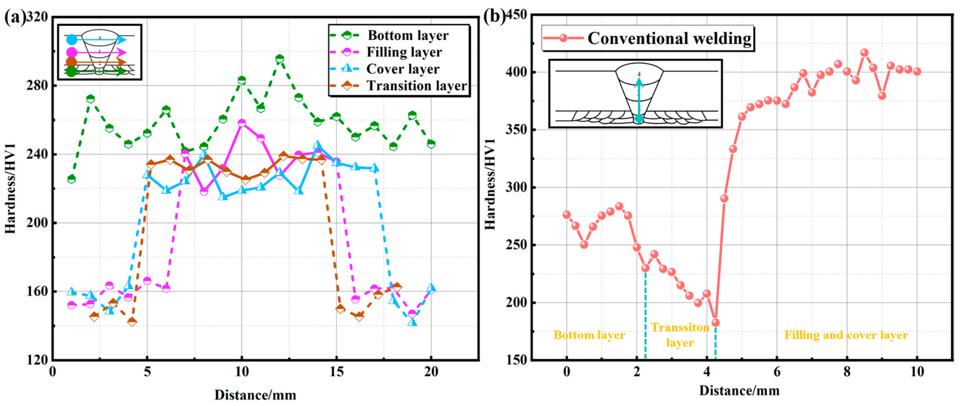
Figure 8 presents the microhardness distributions of the two welded joints (The test path is marked with arrows in the figure). Figure 8a shows the microhardness distribution across different weld passes of the full high-alloy filler metal welded joint, while Figure 8b shows the microhardness distribution along the weld direction of the hybrid filler metal welded joint. The hardness of the X65 base metal was approximately 150–160 HV1, which was lower than that of the weld metal regions. It should be noted that the hardness of the Ni825 liner base material was not separately measured in the present hardness profile, because the hardness analysis mainly focused on the weld passes, fusion zones, heat-affected zones, and the X65-side base metal region.
As shown in Figure 8a, the hardness of the weld region in the full high-alloy filler metal welded joint is generally higher than that of the X65 base metal. The hardness values are mainly distributed in the range of 220–260 HV1, with local values reaching 280–300 HV1. Although slight fluctuations are observed among different weld passes, the overall hardness variation is relatively smooth. This indicates good mechanical uniformity among the weld passes under the unified ERNiCrMo-3 filler metal system. The relatively high hardness of the root pass may be related to stronger base metal dilution, a higher cooling rate, and the segregation of Nb and Mo in the interdendritic regions. Combined with the preceding microstructural and EDS analyses, the weld metal in the full high-alloy filler metal welded joint is mainly composed of γ-Ni cellular/columnar dendrites. Although a narrow compositional transition zone exists near the fusion line, the current hardness results do not show any sharp abnormal hardness peak.
In contrast, the hybrid filler metal welded joint shows a more heterogeneous hardness distribution. The hardness of the root pass is approximately 250–285 HV1, which corresponds to the nickel-based weld solidification microstructure. The hardness decreases significantly in the transition pass, with the minimum value reaching approximately 180–210 HV1. However, the hardness increases rapidly in the filler and covering passes and remains at approximately 360–410 HV1. This sharp hardness variation is closely related to the microstructural and compositional changes in the hybrid filler metal welded joint. The preceding SEM results show that the root and transition passes are mainly composed of nickel-based γ-Ni dendritic solidification microstructures, whereas the filler and covering passes are dominated by steel-based transformation microstructures. The EDS results indicate the presence of a compositional transition zone between the transition pass and the filler pass, where the Fe content gradually increases, while the Ni, Cr, and Mo contents decrease. This gradual elemental transition mainly reflects interpass remelting, dilution, and metallurgical mixing, rather than a sudden compositional jump. Therefore, the sharp increase in hardness observed near the transition/filler-pass boundary should not be attributed simply to the increase in Fe content. Instead, it is mainly associated with the abrupt change in the filler metal system and microstructure from the Ni-based γ dendritic transition pass to the Fe-based CHE507 filler pass. The steel-based filler and covering passes are dominated by harder transformation microstructures formed during weld cooling, leading to significantly higher hardness. The local compositional transition may further affect the transformation behavior and contribute to local hardness variation, but it is not the sole cause of the hardness discontinuity. Therefore, interpass remelting, dilution, and metallurgical mixing at the transition pass/filler pass interface are important reasons for the sharp local hardness variation in the hybrid filler metal welded joint. Overall, compared with the full high-alloy joint, the hybrid filler metal welded joint exhibits stronger compositional, microstructural, and mechanical heterogeneity. In particular, the hardness transition zone between the transition and filler passes may become a potential region susceptible to local hardening and embrittlement.

3.3.2. Strength

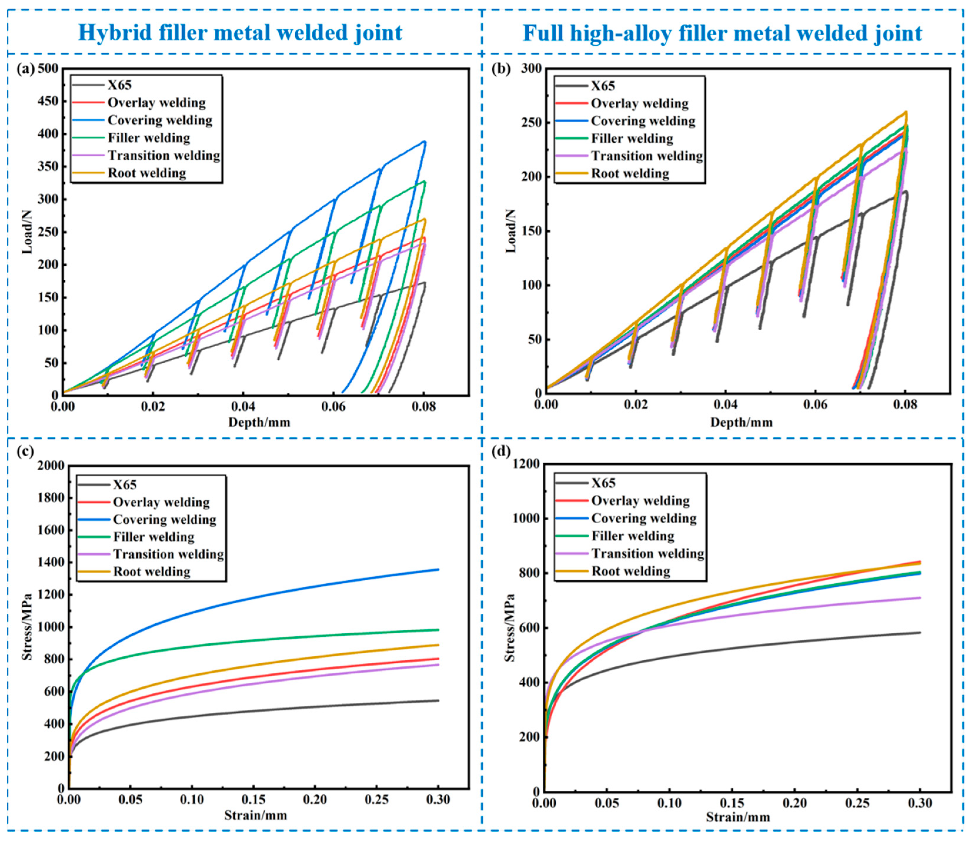
Figure 9 shows the indentation load–depth curves and stress–strain curves of different regions in the two welded joints. As shown in Figure 9a,c, the hybrid filler metal welded joint exhibits obvious differences in local mechanical properties among different regions. At the same indentation depth, the covering and filler passes show higher loads than the other regions, indicating their higher local strength and stronger resistance to deformation. In contrast, the transition pass, overlay pass, and X65 base metal exhibit lower indentation loads. This indicates pronounced mechanical heterogeneity along the weld thickness direction in the hybrid filler metal welded joint. This result is consistent with the preceding microstructural observations, elemental distribution analysis, and hardness results. In comparison, the full high-alloy filler metal welded joint shows a more uniform local mechanical response. As shown in Figure 9b,d, except for the X65 base metal, the load–depth curves and stress–strain curves of the weld passes are relatively close to each other. No obvious strength discontinuity is observed. This is mainly attributed to the use of ERNiCrMo-3 nickel-based filler metal in all weld passes of the full high-alloy joint. As a result, the weld metal has a relatively consistent microstructure and composition, leading to better mechanical uniformity among the weld passes.
Overall, the hybrid filler metal welded joint exhibits more pronounced microstructural, compositional, and mechanical heterogeneity. In particular, the local property discontinuity near the transition pass/filler pass interface may induce more severe stress concentration and damage accumulation during side bending. In contrast, the full high-alloy filler metal welded joint effectively reduces local property differences among weld passes, which is beneficial for improving the overall deformation compatibility of the joint. These results further confirm that the filler metal system is the main factor responsible for the differences in local mechanical properties between the two welded joints.

3.4. Numerical Simulation Results

3.4.1. Stress and Damage Distribution

To further investigate the deformation mechanism and local damage evolution of welded joints under side-bending conditions, a finite element model was developed. The constitutive parameters of different regions were derived from the local stress–strain relationships obtained by instrumented indentation tests. Figure 10, Figure 11 and Figure 12 present the spatial distributions of Von Mises stress, equivalent plastic strain (PEEQ), and damage variable (SDEG) at a punch displacement of 10 mm. At this loading stage, pronounced nonlinear plastic deformation had occurred in the joint. This condition was therefore used to assess the effect of mechanical heterogeneity on stress concentration and damage evolution in different filler metal systems.
Figure 11 shows the mechanical response distribution of the hybrid filler metal welded joint at a punch displacement of 10 mm. The Von Mises stress field indicates a pronounced stress concentration near the transition pass/filler pass interface. This suggests that the abrupt local mechanical-property mismatch makes this heterogeneous interface an important path for shear load transfer. The equivalent plastic strain (PEEQ) distribution further shows that plastic deformation is not uniformly distributed within the weld. Instead, it is shifted toward the X65 base metal side, where the yield strength is relatively lower. This behavior reflects the strong strength–ductility mismatch within the hybrid filler metal welded joint. The higher local strength of the transition/filler region restricts the continuous transfer of plastic strain, leading to strain accumulation in the lower-strength region. The damage variable (SDEG) distribution further confirms the effect of this deformation incompatibility. The local SDEG peak in the filler pass reaches 0.9175, indicating severe damage accumulation and a potential risk of microcrack initiation in this region.
Figure 12 shows the mechanical response of the full high-alloy filler metal welded joint under the same bending condition. The Von Mises stress contour shows a distinct inclined high-stress bearing band within the joint, which corresponds to the transition region. This region can sustain higher stress during bending because of its relatively high local yield strength. The PEEQ distribution indicates that plastic deformation near the interface is still somewhat nonuniform due to the difference between the adjacent materials. However, the full high-alloy filler metal system reduces the local property mismatch among weld passes. As a result, the strain distribution becomes broader, and plastic deformation can be more effectively accommodated by the matrix on both sides of the interface. In terms of damage evolution, the maximum SDEG value in the full high-alloy welded joint is only 0.5889. Compared with the hybrid filler metal welded joint, the damage distribution is more gradual, which helps avoid rapid local damage accumulation. These results suggest that the full high-alloy filler metal system improves deformation compatibility and delays localized damage accumulation under side-bending loading.

3.4.2. Quantitative Analysis of Local Mechanical Responses

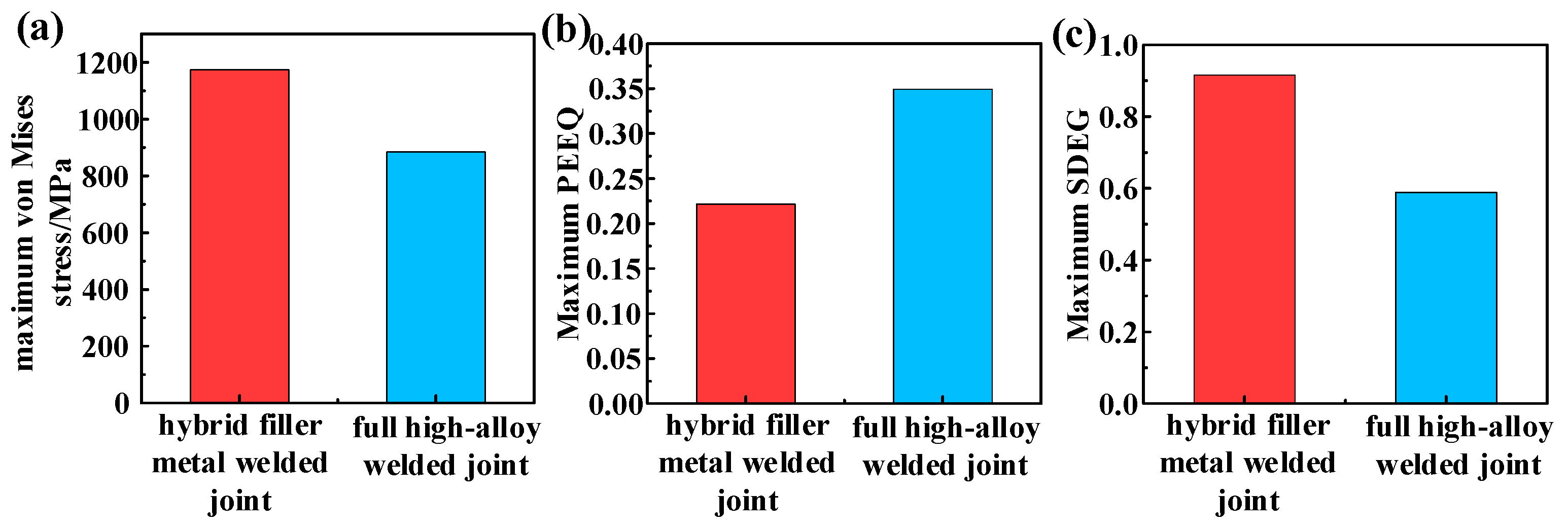
To quantitatively compare the mechanical responses of the two welded joints, Figure 13 summarizes the maximum Von Mises stress, maximum equivalent plastic strain (PEEQ), and maximum damage variable (SDEG) at a bending displacement of 10 mm. The results show that the hybrid filler metal welded joint exhibits higher maximum Von Mises stress and SDEG values than the full high-alloy filler metal welded joint. However, its maximum PEEQ remains at a relatively lower level. This combination of high stress, high damage, and limited plastic strain indicates that severe local strength mismatch in the hybrid joint promotes stress concentration at the heterogeneous interface. As a result, plastic deformation is restricted and cannot effectively spread into the surrounding matrix, leading to earlier local damage accumulation. In contrast, the full high-alloy filler metal welded joint shows a higher PEEQ peak, indicating a greater capacity for plastic strain accommodation. This broader plastic deformation helps reduce local stress concentration and delays damage initiation and evolution.
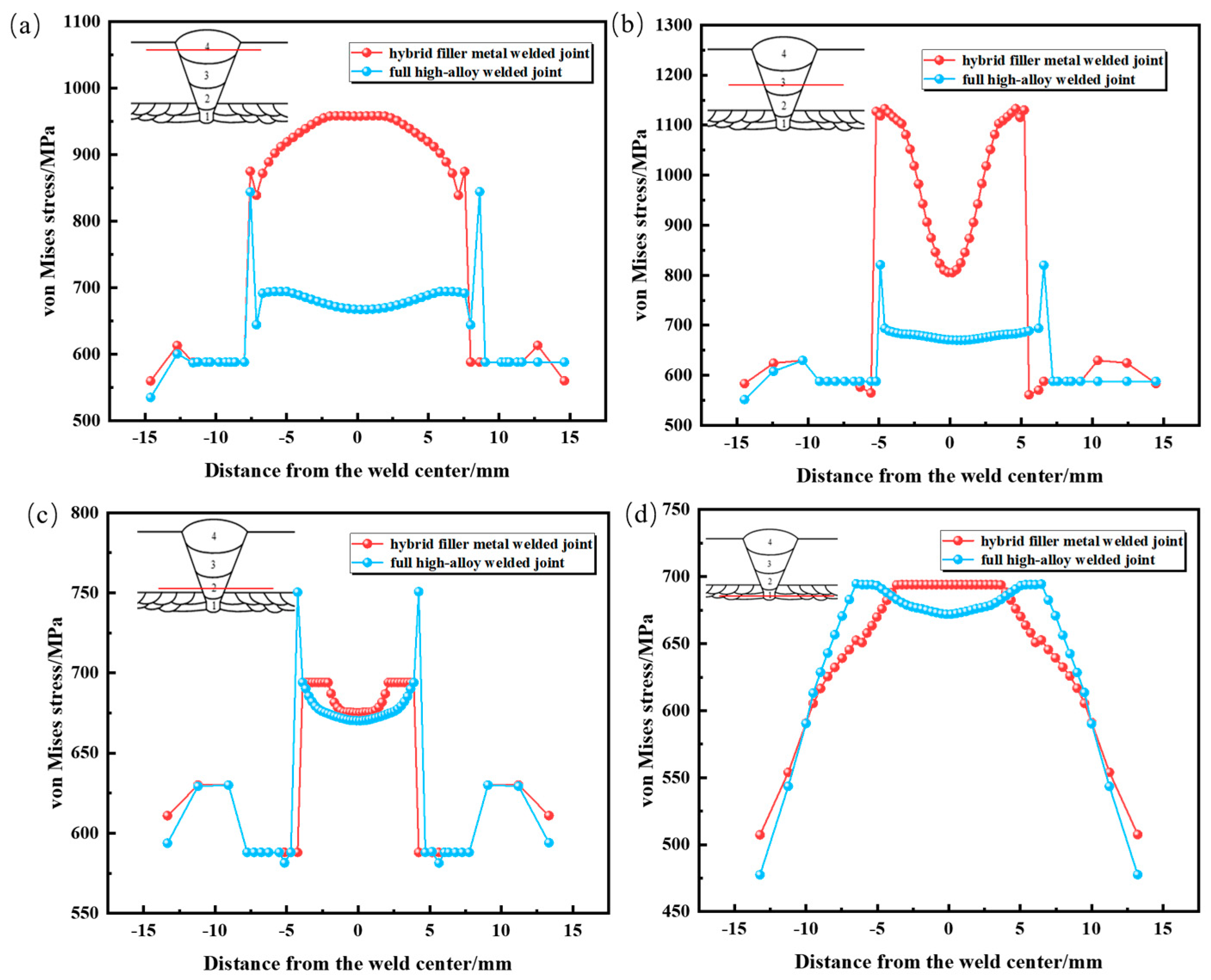
Figure 14 shows the transverse Von Mises stress distributions in the capping, filler, transition, and root passes of the two welded joints. In the capping and filler passes (Figure 14a,b), the hybrid filler metal welded joint shows a higher stress level in the weld region. This is mainly due to the higher yield strength and hardness of the carbon-steel weld metal in these passes. A steep stress gradient is also observed near the fusion line, indicating a strong mechanical mismatch between the weld metal and the X65 base metal. In contrast, the full high-alloy filler metal welded joint shows smoother stress distributions in the same regions. This is attributed to the more uniform constitutive properties of the nickel-based weld metal, which reduce the stress gradient across the fusion line. In the transition and root passes (Figure 14c,d), both joints show relatively smooth stress profiles. This is because these passes were deposited using the same ERNiCrMo-3 filler metal in both welding procedures. Therefore, the stress concentration caused by the upper carbon-steel weld passes in the hybrid joint is mainly limited to the upper heterogeneous interface and does not significantly extend into the lower nickel-based weld passes.
Overall, the numerical simulation results indicate that the full high-alloy filler metal welded joint exhibits better deformation compatibility under side-bending loading. In the hybrid filler metal welded joint, the pronounced mechanical mismatch near the transition pass/filler pass interface leads to stress concentration and localized damage accumulation. Plastic deformation is mainly restricted to a narrow region near the heterogeneous interface, which reduces the overall deformation coordination of the joint. In contrast, the full high-alloy filler metal welded joint shows a more uniform stress and strain distribution due to the consistent filler metal system. These results confirm that the full high-alloy filler metal system improves deformation compatibility by reducing mechanical heterogeneity and stress concentration sensitivity within the welded joint.

4. Conclusions

This study focused on the welded joints of X65/Ni825 bimetallic composite pipes. The microstructure, elemental transition behavior, and local mechanical properties of different weld passes and fusion zones in the full high-alloy filler metal welded joint and the hybrid filler metal welded joint were comparatively investigated. The main conclusions are as follows:
  • In the full high-alloy filler metal welded joint, all weld passes are mainly composed of γ-Ni solid-solution cellular and columnar dendrites, showing good microstructural uniformity, with hardness ranging from 220 to 260 HV1. In contrast, the hybrid filler metal welded joint exhibits a distinct passed microstructure. The root and transition passes are characterized by nickel-based dendritic solidification microstructures, whereas the filler and capping passes transform into ferrite-dominated microstructures, with hardness increasing sharply from 180–210 HV1 to 360–410 HV1.
  • Elemental transition in the full high-alloy filler metal welded joint mainly occurs near the fusion line between the nickel-based weld metal and the X65 base metal. It is characterized by an increase in Fe content and a decrease in Ni, Cr, and Mo contents, forming a narrow compositional transition zone of approximately 50–100 μm in width. Among the different fusion zones, the filler pass fusion zone shows stronger Fe dilution, while the capping pass fusion zone exhibits a sharper compositional transition. In the hybrid filler metal welded joint, a distinct interpass compositional transition zone is formed between the transition and filler passes, indicating local remelting, dilution, and metallurgical mixing in this region.
  • The full high-alloy filler metal welded joint shows relatively smooth hardness and local strength distributions, indicating good mechanical uniformity among the weld passes. In contrast, the hybrid filler metal welded joint exhibits obvious hardness and strength discontinuities near the transition pass/filler pass interface, with a hardness difference of approximately 180 HV1, suggesting stronger local mechanical heterogeneity in this region.
  • The side-bending simulation results show that stress, plastic strain, and damage in the hybrid filler metal welded joint tend to concentrate near the transition pass/filler pass interface, with a maximum SDEG of 0.9175. In contrast, the full high-alloy filler metal welded joint exhibits better deformation compatibility and a more uniform damage distribution, with a maximum SDEG of only 0.5889. Therefore, the full high-alloy filler metal system is beneficial for reducing microstructural, compositional, and mechanical discontinuities within the weld, thereby improving the bending resistance of the welded joint.

Author Contributions

Conceptualization, B.H. and H.Y.; methodology, B.H., X.F., H.Y., X.L. and L.L.; software, X.F. and Y.X.; validation, X.F. and Z.W.; formal analysis, Z.W.; investigation, X.F., H.Y., Y.X. and Z.W.; resources, B.H., X.L. and L.L.; data curation, X.F. and H.Y.; writing—original draft, X.F.; writing—review and editing, B.H., X.F., X.L. and L.L.; visualization, X.F., H.Y. and Y.X.; supervision, B.H., X.L. and L.L.; project administration, B.H., X.L. and L.L.; funding acquisition, B.H. All authors have read and agreed to the published version of the manuscript.

Funding

This work was supported by the National Key R&D Program of China (No. 2021YFA1000103) and the Key Research and Development Plan of Shandong Province (No. 2022CXGC010202).

Data Availability Statement

The original contributions presented in this study are included in the article. Further inquiries can be directed to the corresponding author.

Conflicts of Interest

Xianqiao Fu was employed by China Petroleum Engineering & Construction Corp. North China Company, Renqiu 062550, China. The remaining authors declare that the research was conducted in the absence of any commercial or financial relationships that could be construed as a potential conflict of interest.

References

  1. Bunaziv, I.; Olden, V.; Akselsen, O.M. Metallurgical Aspects in the Welding of Clad Pipelines—A Global Outlook. Appl. Sci. 2019, 9, 3118. [Google Scholar] [CrossRef]
  2. Wang, B.; Zhang, T.; Liu, Y.; Cui, G. Corrosion Damage Behavior of X65/Incoloy 825 Welded Bimetallic Composite Pipe in H2S Environment. Front. Mater. 2021, 8, 709101. [Google Scholar] [CrossRef]
  3. Zhang, N.; Zeng, D. Research on TIG welding gap corrosion resistance of X52/825 metallurgical clad pipein H2S/CO2 environment. Anti-Corros. Methods Mater. 2019, 66, 412–417. [Google Scholar] [CrossRef]
  4. Stradomski, G.; Rydz, D.; Henryk, D. Bimetal plate St3S+Cu. Metalurgija 2005, 44, 147–150. [Google Scholar]
  5. Mróz, S.; Szota, P.; Stefanik, A.; Wąsek, S.; Stradomski, G. Analysis of Al-Cu Bimetallic Bars Properties After Explosive Welding and Rolling in Modified Passes. Arch. Metall. Mater. 2015, 60, 427–432. [Google Scholar] [CrossRef]
  6. Wąsek, S.; Mróz, S.; Stradomski, G.; Laber, K.B. The Analysis of Al-Cu Bimetallic Bars Bond Layers Joined by the Explosive Method. Solid State Phenom. 2013, 199, 508–513. [Google Scholar] [CrossRef]
  7. Wang, L.; Wu, D.; Xu, M.; Hu, Y.; Zhou, P. Microstructure and mechanical properties of L415/N08825 bimetallic composite pipe welded joint using GTAW + SMAW. Arch. Civ. Mech. Eng. 2022, 23, 18. [Google Scholar] [CrossRef]
  8. Ning, Y.Q.; Qiu, S.; Tang, L.; Tang, L.; Li, Y.; Yang, M. Study on Microstructure and Properties of Welded Joint of L360QS/N08825 Bimetallic Composite Pipe. J. Mater. Eng. Perform. 2024, 34, 1685–1694. [Google Scholar] [CrossRef]
  9. Wang, B.; Lan, H.; Lei, B. Effect of Welding Method on Microstructure and Mechanical Properties of L360QS/N08825 Composite Pipe Welded Joint. Trans. Indian Inst. Met. 2020, 73, 629–643. [Google Scholar] [CrossRef]
  10. Wang, B.; Lan, H.; Lei, B. Analysis on Fracture Toughness of the L360QS/N08825 Bimetallic Composite Pipe Welded Joint. Adv. Mater. Sci. Eng. 2019, 2019, 2983506. [Google Scholar] [CrossRef]
  11. Wang, L.; Wu, D.; Cui, C.; Wen, P.; Xu, M.; Zhou, P.; Hu, Y. In situ observation on fracture behavior of the three-phase zone of the L415/N08825 bimetallic composite pipe welded joint. Eng. Fract. Mech. 2022, 276, 108898. [Google Scholar] [CrossRef]
  12. Wang, L.; Wu, D.; Xu, M.; Zhou, P.; Hu, Y. The fracture resistance and crack propagation path of L415/N08825 bimetallic composite pipe welded joint. Theor. Appl. Fract. Mech. 2022, 122, 103656. [Google Scholar] [CrossRef]
  13. Wang, B.; Lei, B.-B.; Wang, W.; Xu, M.; Wang, L. Investigations on the crack formation and propagation in the dissimilar pipe welds involving L360QS and N08825. Eng. Fail. Anal. 2015, 58, 56–63. [Google Scholar] [CrossRef]
  14. Gao, Z.; Han, B.; Li, L.; Ma, G.; Niu, S. Numerical simulation of residual stress in post internal-welding process of bimetal composite pipe and optimization of welding sequence. Int. J. Press. Vessel. Pip. 2022, 199, 104730. [Google Scholar] [CrossRef]
  15. Lázaro-Lobato, L.Á.; Gutiérrez-Vargas, G.; Curiel-López, F.F.; López-Morelos, V.H.; Ramírez-López, M.D.C.; Verduzco-Juárez, J.C.; Taha-Tijerina, J.J. Effect of Ni-Based Buttering on the Microstructure and Mechanical Properties of a Bimetallic API 5L X-52/AISI 316L-Si Welded Joint. Metals 2025, 15, 824. [Google Scholar] [CrossRef]
  16. Kangazian, J.; Shamanian, M.; Ashrafi, A. Dissimilar welding between SAF 2507 stainless steel and Incoloy 825 Ni-based alloy: The role of microstructure on corrosion behavior of the weld metals. J. Manuf. Process. 2017, 29, 376–388. [Google Scholar] [CrossRef]
  17. Silva, C.C.; Miranda, H.C.D.; Motta, M.F.; Farias, J.P.; Afonso, C.R.M.; Ramirez, A.J. New insight on the solidification path of an alloy 625 weld overlay. J. Mater. Res. Technol. 2013, 2, 228–237. [Google Scholar] [CrossRef]
  18. Mohammadi Zahrani, E.; Alfantazi, A.M. High temperature corrosion and electrochemical behavior of INCONEL 625 weld overlay in PbSO4–Pb3O4–PbCl2–CdO–ZnO molten salt medium. Corros. Sci. 2014, 85, 60–76. [Google Scholar] [CrossRef]
  19. Nelson, T.W.; Lippold, J.C.; Mills, M.J. Investigation of boundaries and structures in dissimilar metal welds. Sci. Technol. Weld. Join. 1998, 3, 249–255. [Google Scholar] [CrossRef]
  20. Nelson, T.; Lippold, J.; Mills, M. Nature and evolution of the fusion boundary in ferritic-austenitic dissimilar weld metals. Part 1—Nucleation and growth. Weld. J. 1999, 78, 329s–337s. [Google Scholar]
  21. Nelson, T.; Lippold, J. Hydrogen-Induced Cracking along the Fusion Boundary of Dissimilar Metal Welds. Weld. J. 1999, 78, 31s–37s. [Google Scholar]
  22. Hou, J.; Peng, Q.; Takeda, Y.; Kuniya, J.; Shoji, T. Microstructure and stress corrosion cracking of the fusion boundary region in an alloy 182-A533B low alloy steel dissimilar weld joint. Corros. Sci. 2010, 52, 3949–3954. [Google Scholar] [CrossRef]
  23. Hou, J.; Peng, Q.J.; Takeda, Y.; Kuniya, J.; Shoji, T.; Wang, J.Q.; Han, E.H.; Ke, W. Microstructure and mechanical property of the fusion boundary region in an Alloy 182-low alloy steel dissimilar weld joint. J. Mater. Sci. 2010, 45, 5332–5338. [Google Scholar] [CrossRef]
  24. GB/T 4340.1-2024; Metallic Materials—Vickers Hardness Test—Part 1: Test Method. State Administration for Market Regulation and Standardization Administration of the People’s Republic of China: Beijing, China, 2024.
  25. GB/T 39635-2020; Metallic Materials—Measurement of Indentation Tensile Properties and Residual Stresses by an Instrumented Indentation Test. China Standards Press: Beijing, China, 2020.
Figure 1. Groove and sequence of hybrid filler metal welding and full high-alloy filler metal welding: (a) groove; (b) welding sequence.
Metals 16 00764 g001
Figure 2. 3D finite element mesh model of the welded joint: (a) hybrid filler metal welded joint; (b) full high-alloy filler metal welded joint; (c) three-point bending loading setup.
Metals 16 00764 g002
Figure 3. Microstructure of the hybrid-welded joint: (a) root pass; (b) transition pass; (c) fill pass; (d) cap pass.
Metals 16 00764 g003
Figure 4. Microstructure of the full high-alloy welded joint: (a) root pass; (b) transition pass; (c) fill pass; (d) cap pass.
Metals 16 00764 g004
Figure 5. EDS results and SEM images of the fusion zone between the filler pass and transition pass of hybrid filler metal welded joint: (a) SEM image; (b) EDS scan path; (c) EDS results.
Metals 16 00764 g005
Figure 6. Microstructure of the fusion zones between different weld passes and the base metal: (a) transition pass; (b) filler pass; (c) covering pass.
Metals 16 00764 g006
Figure 7. EDS results and SEM images of the fusion zones between different weld passes and the base metal in the joint welded with full high-alloy filler metals: (a) transition pass; (b) filler pass; (c) covering pass.
Metals 16 00764 g007
Figure 8. Hardness results of the welded joints: (a) hardness of different weld passes in the full high-alloy welded joint; (b) hardness along the weld in the hybrid filler metal welded joint.
Metals 16 00764 g008
Figure 9. Load–depth curves and stress–strain curves of different regions in the two welded joints: (a) load–depth curves of the hybrid filler metal welded joint; (b) load–depth curves of the full high-alloy filler metal welded joint; (c) stress–strain curves of the hybrid filler metal welded joint; (d) stress–strain curves of the full high-alloy filler metal welded joint.
Metals 16 00764 g009
Figure 10. Bending models at a displacement of 10 mm.
Metals 16 00764 g010
Figure 11. Distributions of von Mises stress, equivalent plastic strain (PEEQ) and damage variable (SDEG) in the hybrid filler metal welded joint under lateral bending.
Metals 16 00764 g011
Figure 12. Distributions of von Mises stress, equivalent plastic strain (PEEQ) and damage variable (SDEG) in the full high-alloy filler metal welded joint under lateral bending.
Metals 16 00764 g012
Figure 13. Quantitative comparison of maximum mechanical responses: (a) maximum von Mises stress; (b) maximum PEEQ; (c) maximum SDEG.
Metals 16 00764 g013
Figure 14. Von Mises stress distribution along the transverse direction at different weld passes: (a) cap pass; (b) fill pass; (c) transition pass; (d) root pass.
Metals 16 00764 g014
Table 1. The chemical compositions of X65 (wt%).
CMnPSSiNbTiMoCrNiAlNCuFe
0.091.600.0200.0040.350.060.0250.300.250.300.060.0090.30Bal.
Table 2. The chemical compositions of Ni825 (wt%).
NiCrCMnSiMoCuCoAlTiFe
38–4619.5–23.5≤0.025≤1.0≤0.052.5–3.51.5–3.0≤1.0≤0.20.6–1.2Bal.
Table 3. Welding parameters for full high-alloy filler metal welding.
Welding PassWelding MethodU (V)I (A)Filler MetalInterpass Temp. (°C)Welding Speed (mm/min)
OverlayGTAW12 V135 AERNiCrMo-319.782
RootGTAW9 V90 AERNiCrMo-348.260
TransitionGTAW9 V132 AERNiCrMo-358.7111
FillSMAW22 V91 AERNiCrMo-344.562
CapSMAW22 V95 AERNiCrMo-376.875
Table 4. Welding parameters for hybrid filler metal welding.
Welding PassWelding MethodU (V)I (A)Filler MetalInterpass Temp. (°C)Welding Speed (mm/min)
OverlayGTAW12 V135 AERNiCrMo-319.782
RootGTAW9 V90 AERNiCrMo-348.260
TransitionGTAW9 V132 AERNiCrMo-358.7111
FillSMAW22 V91 ACHE50744.562
CapSMAW22 V95 ACHE50776.875
Table 5. The chemical composition of the welding material (wt%).
CCrNiMnMoSiSPNb + TaFe
ERNiCrMo-30.00722.0164.800.1508.7200.1500.0010.0013.490.18
CHE5070.1500.0400.0200.4000.0070.7000.0300.030-Bal.
Disclaimer/Publisher’s Note: The statements, opinions and data contained in all publications are solely those of the individual author(s) and contributor(s) and not of MDPI and/or the editor(s). MDPI and/or the editor(s) disclaim responsibility for any injury to people or property resulting from any ideas, methods, instructions or products referred to in the content.