1. Introduction
Proton exchange membrane water electrolysis (PEMWE) is regarded as one of the most promising technologies for producing high-purity green hydrogen from renewable electricity. Compared with conventional alkaline water electrolysis, PEMWE has been widely reported to exhibit several advantages, including high current density, compact stack design, rapid dynamic response, high hydrogen purity, and good compatibility with fluctuating renewable electricity inputs [
1,
2]. These features make PEMWE a promising technology for green hydrogen production, especially in scenarios involving intermittent wind and solar power generation [
3,
4]. However, the large-scale commercialization of PEMWE is still restricted by the high cost and long-term durability of key stack components operating in strongly acidic and oxidative environments.
Among the key components of PEM water electrolyzers, bipolar plates (BPPs) and porous transport layers (PTLs) play essential roles in current collection, gas–liquid transport, mechanical support, and separation of adjacent cells. On the anode side, these components are exposed to acidic electrolytes, high oxygen concentration, and high anodic potentials [
5,
6]. Therefore, suitable materials must exhibit excellent corrosion resistance, low interfacial contact resistance, sufficient mechanical strength, and stable performance during long-term operation [
7,
8,
9]. Titanium and titanium-based materials are widely used in PEMWE because of their superior corrosion resistance under acidic and oxidative conditions. However, the extensive use of bulk titanium components remains a cost-related challenge for the large-scale commercialization of PEMWE stacks [
10].
Stainless steel, particularly 316L stainless-steel, has attracted considerable interest as a low-cost substrate for PEMWE metallic components because of its good mechanical properties, mature processing technology, and much lower price compared with titanium. Nevertheless, bare stainless steel is not sufficiently stable under PEMWE anodic conditions. Corrosion and the lack of a stable passivation layer lead to the dissolution of metallic elements, such as Fe, Cr, and Ni, which may contaminate the proton exchange membrane, decrease its proton conductivity, and accelerate cell degradation [
11]. In addition, the passive film formed on stainless steel may increase interfacial contact resistance, causing additional ohmic losses during electrolyzer operation. Therefore, applying protective coatings on stainless steel substrates has become an important strategy for reducing component cost while maintaining the corrosion resistance and conductivity required for PEMWE applications.
Various surface modification and coating technologies have been explored for protecting stainless-steel in PEMWE-related environments, including physical vapor deposition, electroplating, thermal spraying, cold spraying, and carbon- or nitride-based surface treatments [
8]. Among these approaches, titanium-based protective coatings are particularly attractive because they can provide chemical compatibility with PEMWE operating conditions while greatly reducing the use of bulk titanium. A dense and well-bonded titanium coating can serve as a physical barrier to corrosive media, suppress the release of metallic ions from the stainless steel substrate, and form a stable passive layer during electrochemical operation. From the perspective of industrial manufacturing, atmospheric plasma spraying (APS) is a promising technique because of its high deposition efficiency, relatively low equipment cost, flexible coating thickness control, and suitability for large-area metallic components [
12,
13].
However, preparing low-oxide titanium coatings by conventional APS remains challenging. Titanium has a strong affinity for oxygen at elevated temperatures, and molten or semi-molten Ti particles can be rapidly oxidized during flight in the plasma jet. In conventional APS, the plasma plume is directly exposed to ambient air, and oxygen can be entrained into the high-temperature jet before the particles reach the substrate. This process promotes the formation of TiO
2 and other oxide-rich phases in the coating [
14]. Excessive oxidation may change the phase composition, increase coating brittleness, reduce electronic conductivity, and affect corrosion behavior. For PEMWE applications, this issue is particularly important because the coating must simultaneously provide corrosion protection and maintain sufficient electrical conductivity.
Several strategies have been proposed to reduce oxidation during titanium coating deposition, such as vacuum plasma spraying (VPS), low-pressure plasma spraying, controlled-atmosphere spraying, and cold spraying. VPS and low-pressure plasma spraying can effectively reduce oxygen partial pressure and produce high-quality metallic coatings, but they generally require vacuum chambers, complex equipment, and higher operating costs [
15]. Cold spraying can reduce thermal oxidation because the feedstock particles remain largely solid during deposition; however, it usually requires high gas pressure, strict powder characteristics, and sufficient particle impact velocity to obtain dense titanium coatings. These limitations increase process complexity and may restrict large-scale application [
16]. Therefore, developing a simple, economical, and APS-compatible method to suppress titanium oxidation remains significant for low-cost PEMWE component manufacturing.
To better clarify the technical position of the present method, a quantitative comparison of representative Ti coating technologies reported in the literature is summarized in
Table 1. Conventional APS is simple and suitable for large-area deposition, but Ti particles are directly exposed to ambient air, which can result in severe oxidation and nitridation. Shrouded APS can reduce air entrainment through a physical shroud and external inert gas. VPS/LPPS provides stronger oxidation control and dense coatings, but it requires vacuum or low-pressure equipment, which increases cost and limits process flexibility. HVOF spraying can produce relatively dense Ti coatings due to high particle velocity; however, the combustion atmosphere and thermal exposure may still promote oxidation of oxygen-sensitive Ti particles. Cold spraying can largely avoid thermal oxidation because the particles remain below the melting point, although dense Ti coating formation usually requires high gas pressure and high particle velocity. Based on these comparisons, the present study proposes an APS-compatible extended protective nozzle that integrates auxiliary Ar shielding, independent gas-cooling and water-cooling channels, and a Laval-nozzle structure to reduce thermal exposure and particle oxidation under atmospheric conditions [
17].
The extended nozzle was designed with water-cooling and auxiliary argon-shielding channels to reduce the thermal load of the plasma flame and limit the interaction between in-flight Ti particles and ambient air [
13,
22]. In addition, potentiodynamic polarization and short-term potentiostatic tests were performed in 0.5 M H
2SO
4 to assess the corrosion resistance and passivation stability of the coatings under simulated PEMWE anodic conditions [
23]. The purpose of this work is to clarify whether this nozzle-assisted APS strategy can effectively suppress coating oxidation while retaining the practical advantages of atmospheric spraying. The results show that the deposited coating exhibits a continuous lamellar structure with α-Ti(O) as the dominant phase, limited oxidation, and improved electrochemical stability in acidic solution. By regulating nozzle-assisted gas–solid interaction, this work provides a feasible route for preparing titanium protective coatings for low-cost metallic components in PEM water electrolysis.
2. Materials and Methods
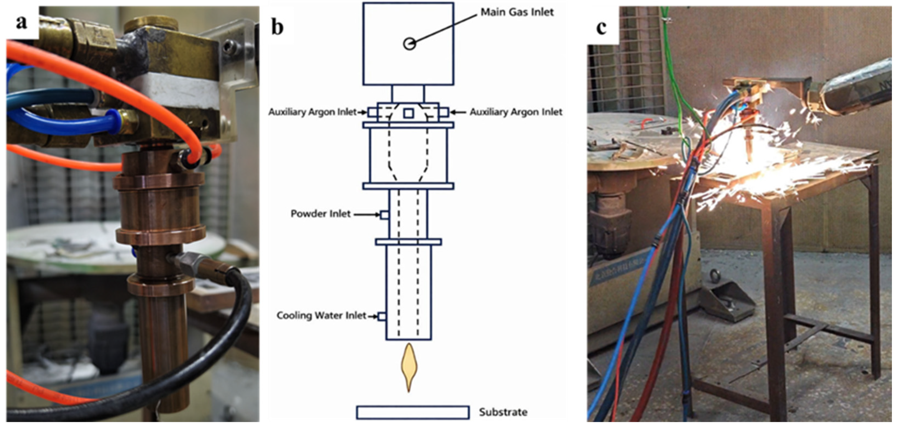
TA1-grade commercially pure titanium powder (TA1, Hangfa New Material Technology (Hebei) Co., Ltd., Nangong, Xingtai, China) was used as the feedstock for plasma spraying. The powder had a spherical morphology, a particle size range of 53–105 μm, and a median particle size (d50) of approximately 75 μm, with a purity higher than 99.9%. The spherical morphology and particle size distribution of the Ti powder are important for determining the particle melting state, spreading behavior, and lamellar stacking during plasma spraying, and therefore have a direct influence on the coating microstructure and oxidation behavior. A 316L stainless-steel plate (30 mm × 30 mm × 1 mm) was employed as the substrate. The self-designed extended protective nozzle and the corresponding low-temperature atmospheric plasma spraying process are shown in
Figure 1. As illustrated in
Figure 1a, the extended nozzle was mounted at the outlet of the plasma torch to prolong the protected region of the plasma jet. The nozzle was designed with integrated water-cooling channels and auxiliary argon gas inlets. The water-cooling system was used to reduce the thermal load on the nozzle body and maintain the structural stability of the hardware during spraying. Meanwhile, the auxiliary argon flow was introduced around the plasma plume to form a local shielding atmosphere, which reduced the direct contact between in-flight Ti particles and ambient air.
Figure 1b schematically shows the spraying process. During deposition, the main plasma gas was supplied through the torch, while Ti powder was injected into the plasma jet through the powder feed inlet. The molten or semi-molten Ti particles were accelerated toward the 316L stainless-steel substrate. Compared with conventional atmospheric plasma spraying, the extended nozzle increased the residence distance of particles in the protected atmosphere and weakened the entrainment of surrounding air into the high-temperature plasma jet. Therefore, oxidation of Ti particles during flight could be partially suppressed before impact and solidification on the substrate [
24]. The actual spraying setup is shown in
Figure 1c, where the plasma jet was directed toward the stainless-steel substrate during coating deposition.
Prior to spraying, 316L stainless-steel substrates with dimensions of 30 mm × 30 mm × 1 mm were ground, ultrasonically cleaned in ethanol, and sandblasted. Coatings were deposited using a Metco 9 MC system with the extended nozzle pre-purged with Ar (150 L/min). Spraying was performed at 400–500 A and 50–55 V with a powder feed rate of 30–35 g/min, using Ar (50–60 L/min) and H2 (8–10 L/min) at a 30 mm stand-off distance.
Considering the use of hydrogen-containing plasma gas and fine Ti powder during the spraying process, appropriate safety measures were implemented. The spraying operation was carried out in a well-ventilated spraying booth equipped with an exhaust system. Before spraying, the gas pipelines and connections were checked for leakage, and the gas flow rates were controlled by calibrated flowmeters. Argon was introduced before hydrogen to purge the gas lines and spraying region, and hydrogen was shut off before argon during the shutdown procedure. Open flames and ignition sources were strictly avoided near the spraying area. In addition, oversprayed Ti powder was collected using the exhaust and dust-collection system, and the accumulated powder was handled carefully to minimize the risk of ignition or dust explosion.
The microstructural characteristics and elemental distributions were examined using scanning electron microscopy (SEM, Zeiss Supra 55, Carl Zeiss AG, Oberkochen, Germany) equipped with energy-dispersive spectroscopy (EDS, Oxford INCAx-act, Oxford Instruments, Abingdon, UK). Phase identification was conducted via X-ray diffraction (XRD, GIIAN XRD-6100, Dandong, China) with Cu Kα radiation. The oxygen and nitrogen contents of the sprayed Ti coatings were quantitatively measured using an ONH5500 oxygen/nitrogen/hydrogen analyzer. Samples were taken from the four Ti coatings prepared under different spraying parameters, namely 400 A 50 V, 400 A 55 V, 500 A 50 V, and 500 A 55 V. The measured O and N contents were used to quantitatively evaluate the reduced-oxide characteristic of the coatings.
The coating thickness was measured from cross-sectional SEM images using the SEM scale bar. For each spraying parameter, five different positions were selected, and the average thickness value was calculated to evaluate the thickness variation among different coatings.
The porosity of the Ti coatings was quantified from cross-sectional SEM images using Image J v1.54g. For each spraying parameter, four SEM images taken from different regions were analyzed, and the average porosity value was calculated. The microhardness of the Ti coatings was measured using a Vickers microhardness tester under a load of 100 gf, corresponding to HV0.1. For each coating, eight indentations were performed at different positions, and the average value and standard deviation were calculated.
Electrochemical tests were conducted in a three-electrode setup in 0.5 M H
2SO
4 to evaluate corrosion and passivation of the Ti coating. The coated sample (1 cm
2), a platinum plate, and an Ag/AgCl electrode acted as the working, counter, and reference electrodes, respectively [
25].
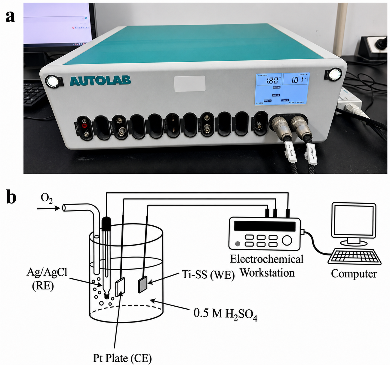
The electrochemical testing system used in this study is shown in
Figure 2.
Figure 2a presents the Autolab electrochemical workstation used for electrochemical measurements and data acquisition. The electrochemical tests were performed in a conventional three-electrode configuration, as schematically illustrated in
Figure 2b. The Ti-coated 316L stainless-steel sample with an exposed area of 1 cm
2 was used as the working electrode, a platinum plate was used as the counter electrode, and a Ag/AgCl electrode was used as the reference electrode. The electrolyte was 0.5 M H
2SO
4 solution, which was used to simulate the acidic environment of PEM water electrolysis. Before testing, high-purity O
2 was bubbled into the electrolyte to create an oxygen-rich condition close to the anodic environment of a PEM water electrolyzer. The Autolab workstation was connected to a computer to control the testing procedure and record the electrochemical response.
All measured potentials vs. Ag/AgCl were converted to the reversible hydrogen electrode (RHE) scale using the Nernst equation:
Potentiodynamic polarization (PDP) was recorded from −0.7 V to 1.8 V (vs. RHE) at a scan rate of 1 mV/s. The short-term durability was assessed by a 6 h potentiostatic test at 1.8 V vs. RHE in O2-saturated 0.5 M H2SO4 solution.
The lab-scale PEM water electrolysis test was conducted using a commercial small PEM electrolyzer to preliminarily evaluate the practical gas production performance of the Ti-coated samples. The electrolyzer was operated in constant-current mode at 8 A. A Nafion 117 membrane-based MEA was used as the core component of the cell. The Ti-coated 316L stainless-steel samples were assembled on the anodic side as the porous transport/current-collecting component. Deionized water was used as the water feed, and the cell was operated under ambient pressure within the recommended operating temperature range of 10–60 °C. The applied current of 8 A corresponds to a theoretical H2 production rate of approximately 60 mL/min. The generated H2 and O2 were collected and measured, and the gas production rates were calculated from the collected gas volume and testing time. The same cell configuration, assembly procedure, and tightening condition were used for all samples to ensure comparability.
3. Results and Discussion
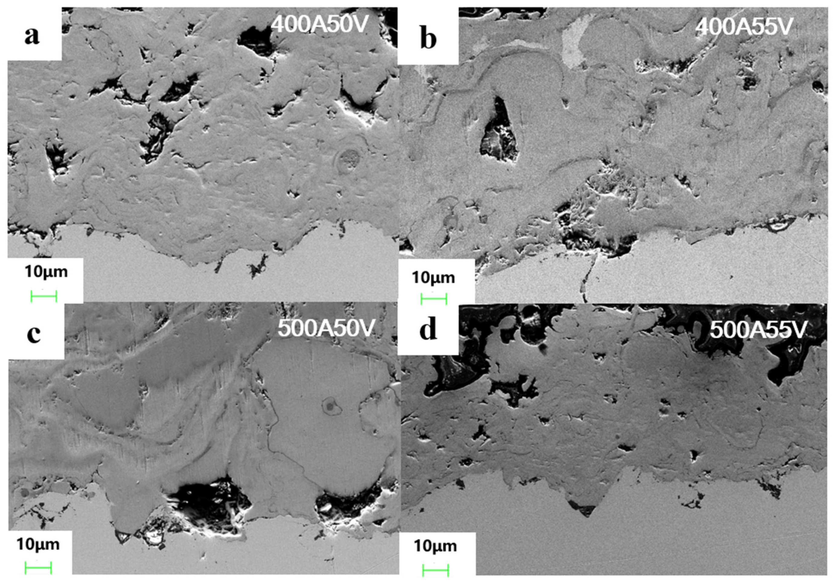
Figure 3 shows the cross-sectional SEM morphologies of the Ti coatings prepared under different plasma-spraying parameters. All coatings exhibit a typical lamellar structure formed by the spreading, rapid solidification, and stacking of molten or semi-molten Ti particles during atmospheric plasma spraying. The coating/substrate interfaces are relatively rough and wavy, which can be attributed to the sandblasting pretreatment of the 316L stainless-steel substrates. This roughened surface is beneficial for enhancing mechanical interlocking between the deposited Ti coating and the stainless-steel substrate. As shown in
Figure 3a–d, the coatings are continuous overall and firmly attached to the substrate, indicating that Ti particles were successfully deposited under all selected spraying conditions. However, some pores, microcracks, and locally unmolten or insufficiently flattened regions can still be observed within the coatings. These defects are commonly associated with the incomplete melting of feedstock particles, rapid cooling during splat formation, and limited filling between adjacent lamellae. Compared with the coatings prepared at lower arc voltage, the coating deposited at higher voltage shows a relatively more compact lamellar structure, suggesting that increasing the plasma power can improve particle melting and flattening behavior. Nevertheless, excessive heat input may also increase the risk of oxidation during particle flight.
The coating thickness was also measured from the cross-sectional SEM images. For each spraying parameter, five positions were measured, and the average thickness was calculated. The average thickness values of the coatings prepared at 400 A 50 V, 400 A 55 V, 500 A 50 V, and 500 A 55 V were approximately 95, 98, 92, and 78 μm, respectively. These results indicate that continuous Ti coatings with thicknesses of approximately 78–98 μm were obtained under the selected spraying parameters. Among the four conditions, the coating prepared at 500 A 55 V exhibited the lowest average thickness.
The porosity and microhardness of the Ti coatings are summarized in
Table 2. The average porosity values of the coatings prepared at 400 A 50 V, 400 A 55 V, 500 A 50 V, and 500 A 55 V were approximately 4.3%, 2.9%, 4.5%, and 3.1%, respectively. All coatings exhibited porosity values below 5%, indicating that relatively compact lamellar coatings were obtained under the selected spraying parameters. The coatings prepared at 400 A 55 V and 500 A 55 V showed lower porosity, suggesting that increasing the arc voltage improved particle melting and splat flattening.
The microhardness values of the coatings were 269 ± 31, 317 ± 28, 285 ± 35, and 343 ± 33 HV0.1 for 400 A 50 V, 400 A 55 V, 500 A 50 V, and 500 A 55 V, respectively. The higher hardness of the 400 A 55 V and 500 A 55 V coatings can be mainly attributed to their lower porosity and more compact lamellar structure. In addition, the slightly higher oxygen and nitrogen contents at higher spraying power may also contribute to the hardness increase through oxygen solid-solution strengthening and limited oxide formation.
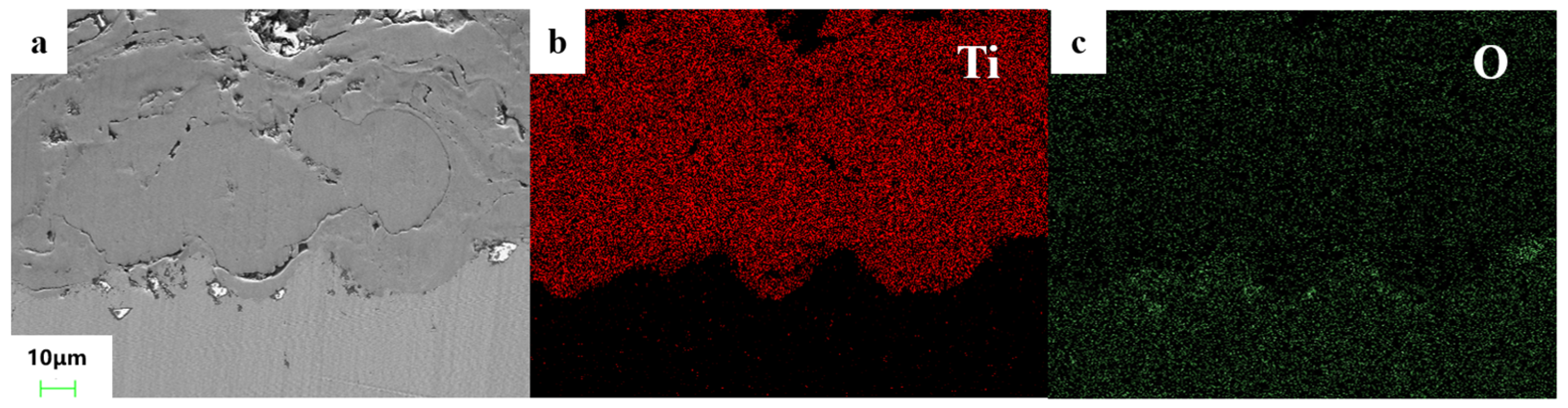
To further investigate the elemental composition of the sprayed coating, EDS elemental mapping was performed on a selected cross-sectional region, as shown in
Figure 4.
Figure 4a shows the selected SEM region of the coating, while
Figure 4b,c present the corresponding Ti and O elemental distributions, respectively. The Ti map shows that titanium is distributed throughout almost the entire coating region, indicating that the coating is mainly composed of Ti. In contrast, only a small amount of oxygen is detected in the coating, suggesting that the oxidation degree of the Ti coating is relatively low.
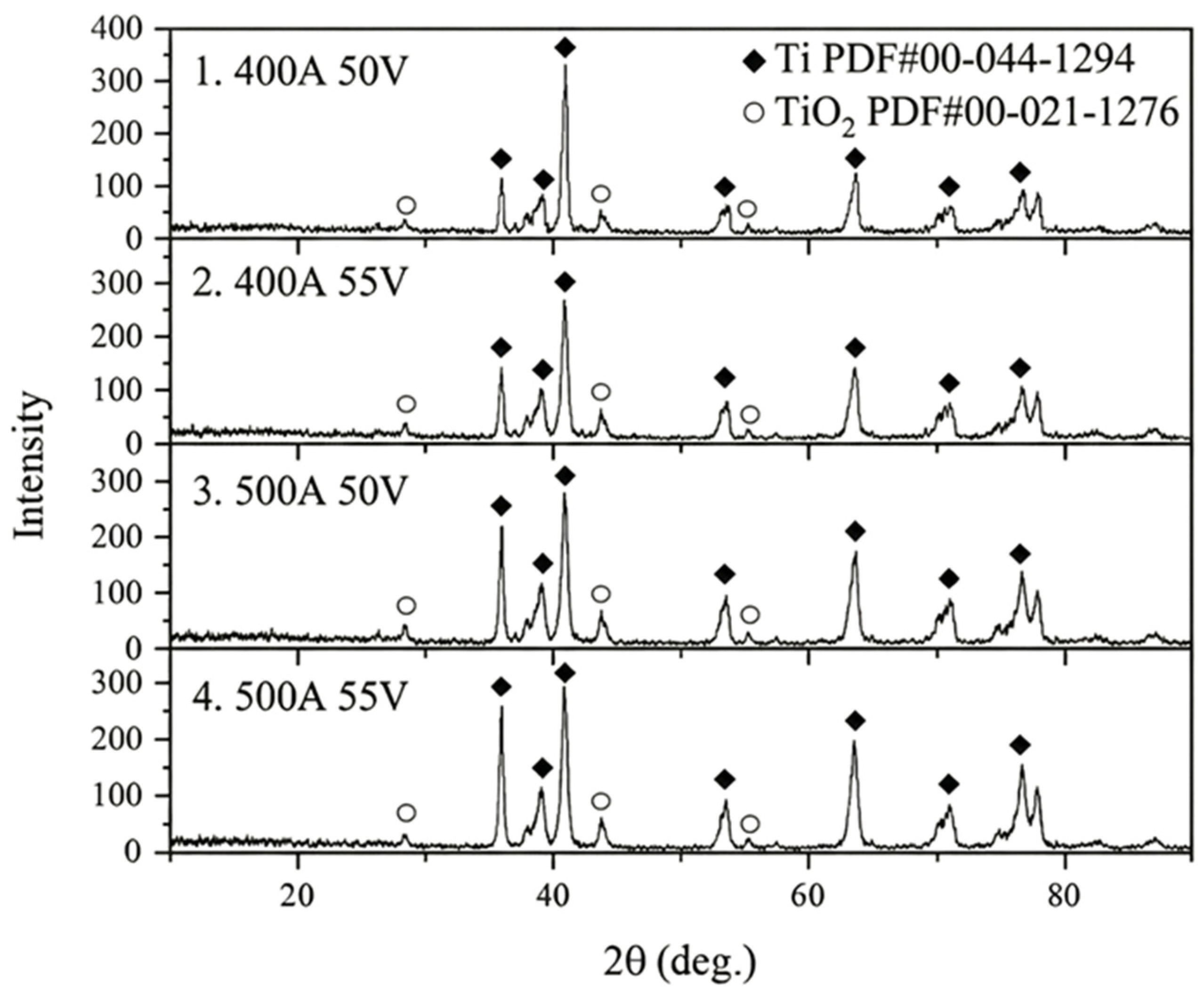
Based on the EDS mapping results, XRD analysis was further conducted to identify the phase composition and oxide formation in the four groups of sprayed Ti coatings, as shown in
Figure 5. The diffraction peaks of all samples are mainly assigned to metallic Ti with a hexagonal close-packed structure, indicating that Ti is the dominant phase in the coatings. Only weak TiO
2 peaks can be observed in the XRD patterns, suggesting that a small amount of titanium oxide was formed during deposition. This result is consistent with the EDS mapping results, in which the coating region was mainly composed of Ti with only a minor oxygen signal.
To further quantitatively evaluate the oxidation and nitridation levels of the sprayed Ti coatings, oxygen and nitrogen contents were measured using an ONH5500 oxygen/nitrogen/hydrogen analyzer. As shown in
Table 3, the oxygen contents of the coatings prepared at 400 A 50 V, 400 A 55 V, 500 A 50 V, and 500 A 55 V were 1.19, 0.95, 1.36, and 1.69 wt.%, respectively. The corresponding nitrogen contents were 0.063, 0.049, 0.072, and 0.087 wt.%, respectively.
Compared with the literature values summarized in
Table 1, the present coatings exhibit relatively low oxygen and nitrogen contents. Conventional APS Ti coatings prepared in an open atmosphere were reported to contain 3.70 wt.% O and 0.097 wt.% N [
18], whereas the present coatings contain only 0.95–1.69 wt.% O and 0.049–0.087 wt.% N. These values are much lower than those of conventional APS and close to those of shrouded APS coatings, for which 0.76 wt.% O and 0.039 wt.% N were reported [
18]. In comparison with other processes, HVOF-sprayed Ti coatings may still show considerable oxide contents because of the combustion atmosphere [
20], while VPS/LPPS and cold spraying can provide stronger oxidation control but require vacuum/low-pressure equipment or high gas pressure and high particle velocity [
21,
22]. Therefore, the present nozzle-assisted APS method provides a practical balance between oxidation/nitridation suppression and atmospheric-process compatibility.
The ONH results also provide experimental evidence for the influence of heat input on oxidation and nitridation during spraying. The coating prepared at 400 A 55 V exhibited the lowest O and N contents, 0.95 wt.% and 0.049 wt.%, respectively, indicating that this condition provided a better balance between particle melting and oxidation suppression. However, when the spraying parameter increased to 500 A 55 V, the O and N contents increased to 1.69 wt.% and 0.087 wt.%, respectively. This result suggests that excessive heat input may increase the thermal exposure of in-flight Ti particles and promote oxidation/nitridation during atmospheric plasma spraying.
In this study, the term “reduced-oxide Ti coating” is defined based on the O/N contents measured by ONH analysis and the phase composition identified by XRD. Specifically, a Ti coating with an oxygen content below 2.0 wt.%, a nitrogen content below 0.10 wt.%, metallic Ti as the dominant XRD phase, and only weak TiO2 diffraction peaks is considered to meet the criterion of a reduced-oxide Ti coating.
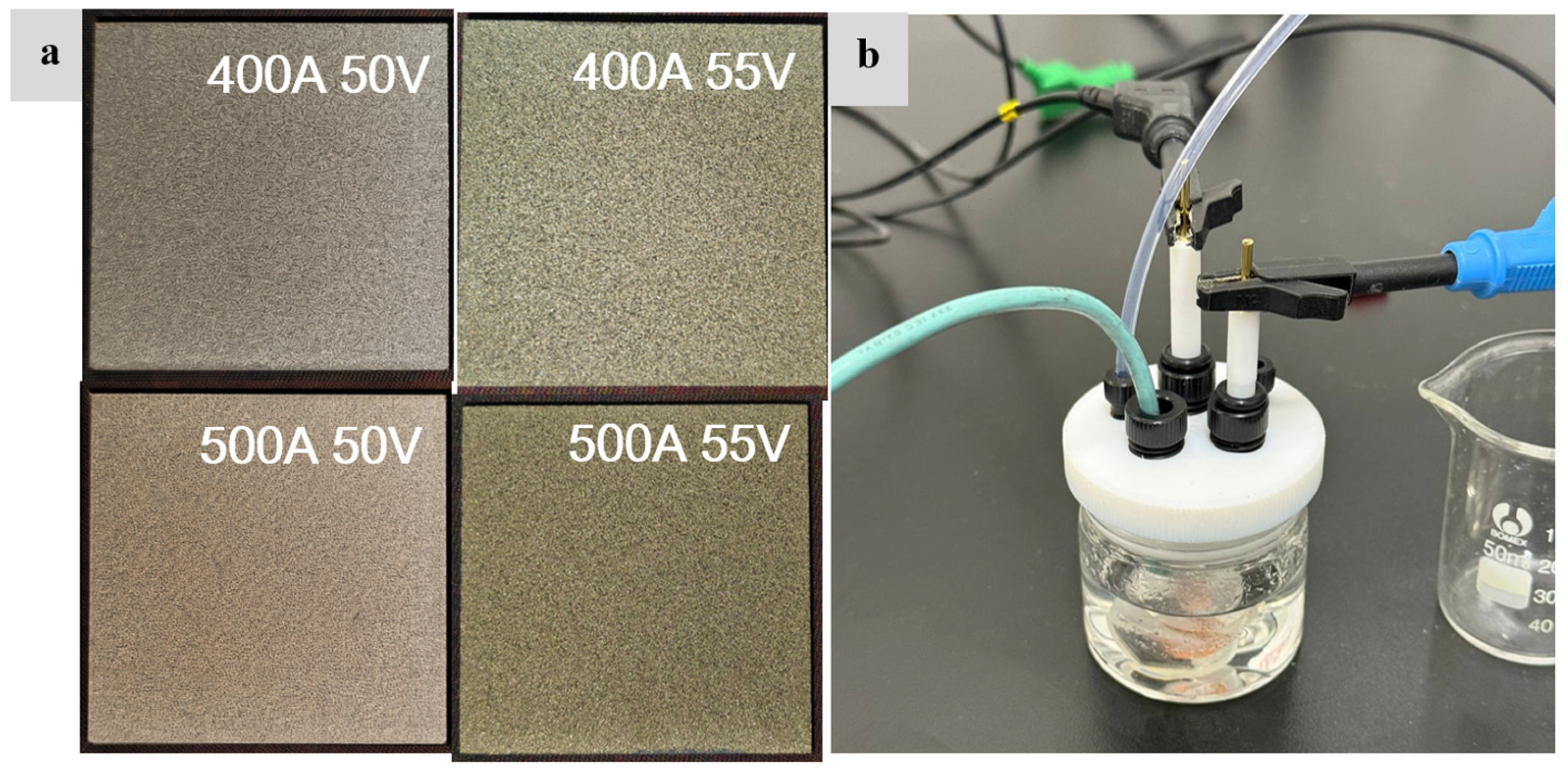
Figure 6 shows the sprayed Ti-coated samples and the electrochemical testing setup. As shown in
Figure 6a, Ti coatings were prepared under four different plasma-spraying parameters, namely 400 A 50 V, 400 A 55 V, 500 A 50 V, and 500 A 55 V. Before electrochemical measurements, the sprayed samples were cut into specimens with an exposed area of 1 cm
2.
Figure 6b shows the three-electrode electrochemical testing system used to evaluate the corrosion resistance and passivation behavior of the Ti coatings in 0.5 M H
2SO
4 solution. The Ti-coated sample was used as the working electrode, while a platinum plate and an Ag/AgCl electrode were used as the counter electrode and reference electrode, respectively. This sample preparation and testing configuration ensured that the electrochemical response of the sprayed Ti coating could be measured under controlled and comparable conditions.
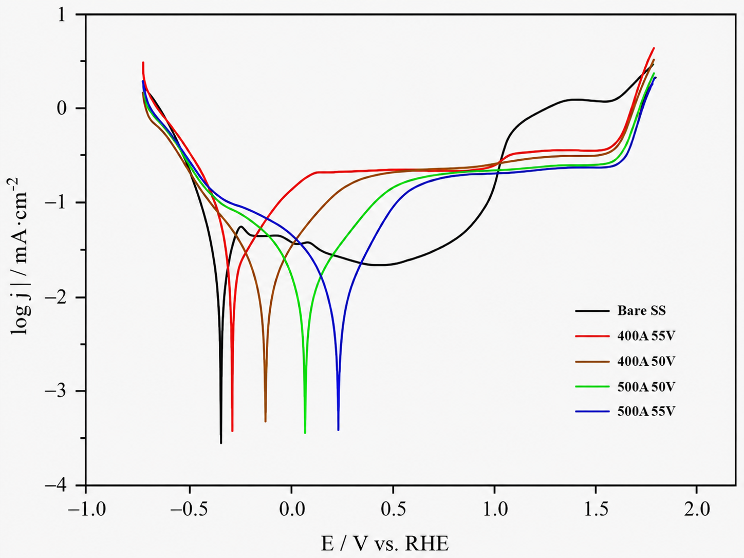
Figure 7 shows the potentiodynamic polarization curves of bare 316L stainless steel and Ti-coated samples prepared under different plasma-spraying parameters in 0.5 M H
2SO
4 solution. The bare stainless steel exhibits a corrosion potential of approximately −0.33 V vs. RHE, while the corrosion potentials of the Ti-coated samples shift to more positive values. The coated samples show corrosion potentials of about −0.28 V, −0.12 V, 0.08 V, and 0.25 V vs. RHE for 400 A 55 V, 400 A 50 V, 500 A 50 V, and 500 A 55 V, respectively. This positive shift indicates that the Ti coatings reduce the corrosion tendency of the 316L stainless-steel substrate in the acidic electrolyte.
In terms of current density, the bare stainless steel shows a relatively unstable polarization behavior. After the initial corrosion region, its anodic current density increases rapidly and reaches a much higher level at potentials above approximately 1.0 V vs. RHE, indicating insufficient stability under strong anodic polarization. In contrast, all Ti-coated samples exhibit relatively stable passive regions over a wide potential range. The passive current density of the coated samples remains mainly around 10−1–10−0.5 mA·cm−2, suggesting the formation of a protective passive film on the Ti coating surface. Among the coated samples, the 500 A 55 V coating shows the most positive corrosion potential and a stable passive region, indicating comparatively better corrosion resistance. At potentials higher than approximately 1.6–1.7 V vs. RHE, the current density of all coated samples increases sharply, which may be related to intensified anodic reactions, passive film instability, or oxygen evolution. Overall, the polarization results demonstrate that the sprayed Ti coatings significantly improve the corrosion resistance of 316L stainless steel in acidic PEMWE-related conditions.
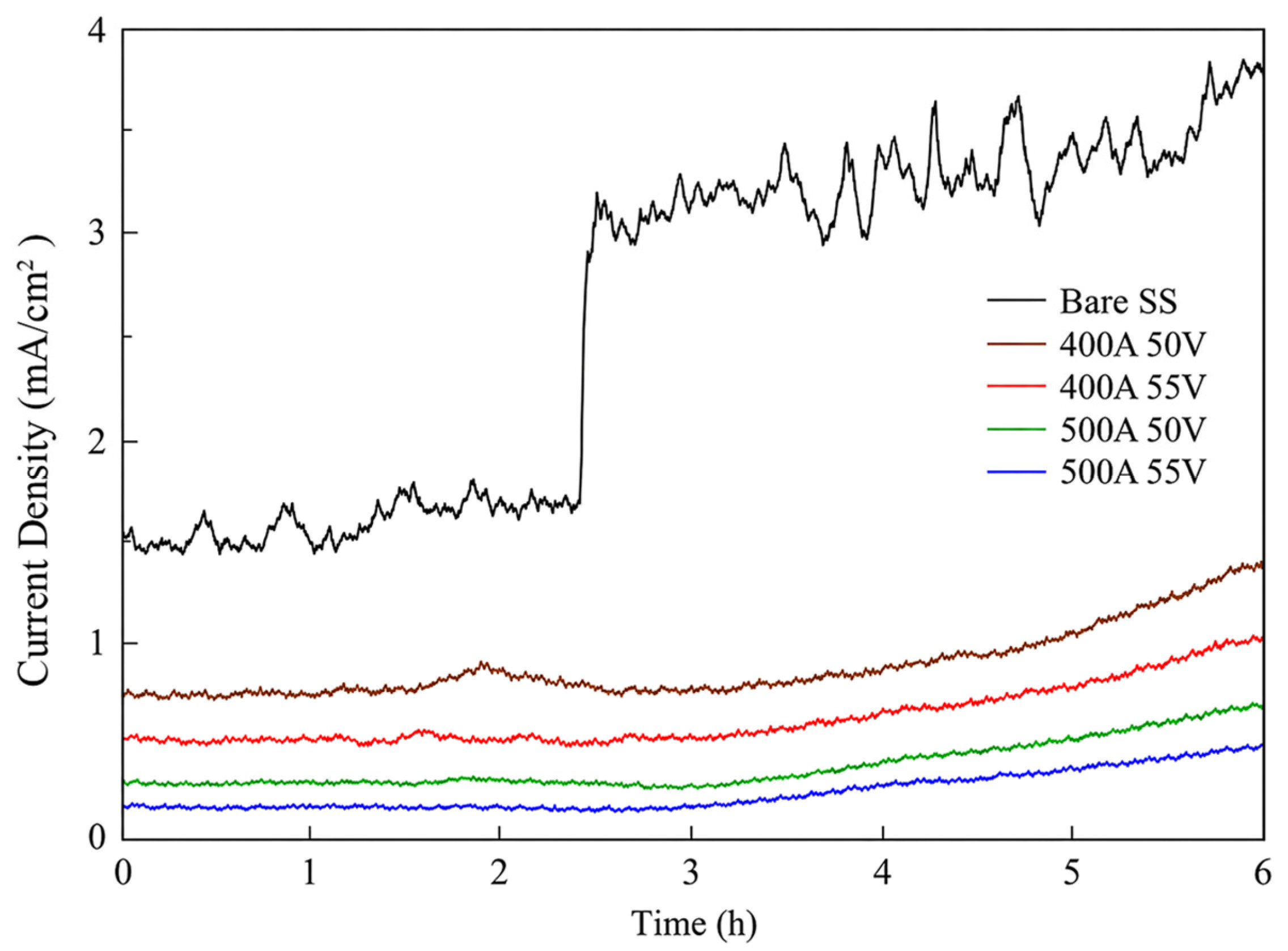
Figure 8 shows the potentiostatic current–time curves of bare 316L stainless steel and Ti-coated samples prepared under different plasma-spraying parameters at 1.8 V vs. RHE for 6 h in O
2-saturated 0.5 M H
2SO
4 solution.
During the 6 h potentiostatic test, bare 316L stainless steel exhibited a high and unstable current response. The current density initially remained at approximately 1.4–1.7 mA/cm2 and then increased sharply after about 2.5 h, followed by strong fluctuations at a high current-density level. This behavior indicates instability or breakdown of the passive film on bare stainless steel under acidic and anodic conditions.
Among the four Ti-coated samples, the 500 A 55 V coating exhibited the lowest current density and the most stable response during the 6 h potentiostatic test. At the end of the test, the current densities of the 400 A 50 V, 400 A 55 V, 500 A 50 V, and 500 A 55 V coatings were approximately 1.3–1.4, 1.0, 0.6–0.7, and 0.4–0.5 mA/cm2, respectively. The current response decreased in the order of 400 A 50 V > 400 A 55 V > 500 A 50 V > 500 A 55 V, indicating that increasing the spraying power improved the short-term electrochemical stability of the coatings. This improvement may be related to the more compact lamellar structure and reduced effective pathways for electrolyte penetration.
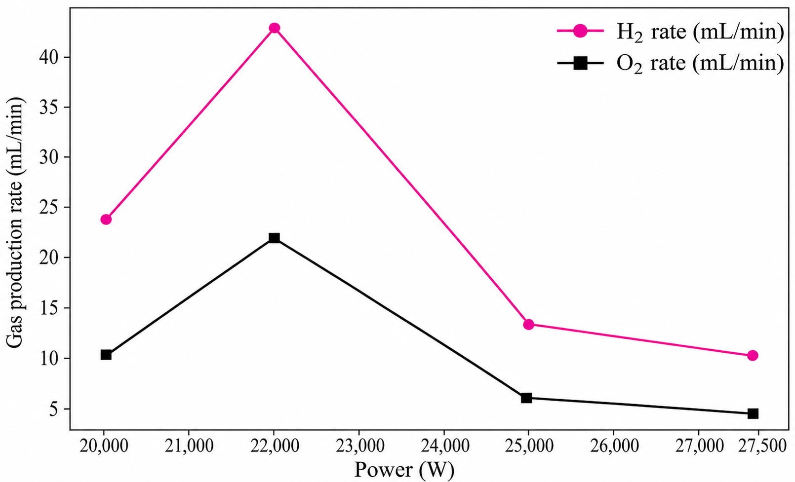
Figure 9 shows the hydrogen and oxygen production rates of the Ti-coated samples prepared under different plasma-spraying powers in a lab-scale electrolyzer. The gas production rates first increase and then decrease with increasing spraying power. When the spraying power is increased from 20 kW (400 A 50 V) to 22 kW (400 A 55 V), the H
2 production rate increases from approximately 24 mL/min to 43 mL/min, while the O
2 production rate increases from approximately 11 mL/min to 22 mL/min. The highest gas production rates are obtained at 22 kW (400 A 55 V), indicating that this spraying condition provides the most favorable electrochemical performance among the tested samples.
When the spraying power is further increased to 25 kW (500 A 50 V) and 27.5 kW (500 A 55 V), both H2 and O2 production rates decrease significantly. At 25 kW (500 A 50 V), the H2 and O2 production rates decrease to approximately 14 mL/min and 7 mL/min, respectively. At 27.5 kW (500 A 55 V), they further decrease to about 11 mL/min and 5 mL/min. This decline suggests that excessive spraying power may negatively affect the coating performance in the electrolyzer. Although higher power can improve particle melting and coating compactness, it may also increase the oxidation degree of Ti particles during deposition. Excessive oxide formation or microstructural defects may reduce the effective conductivity and electrochemical activity of the coating, leading to lower gas production rates.
It should be noted that the trend in the lab-scale electrolyzer performance is not completely identical to that observed in the potentiostatic stability test. The potentiostatic test mainly reflects the corrosion resistance and passivation stability of the coating under a fixed anodic potential, whereas the gas production performance in the lab-scale electrolyzer represents the overall electrochemical behavior of the coated bipolar plate under practical operating conditions. Therefore, the two tests evaluate different aspects of coating performance and are not expected to show identical trends. The 500 A 55 V coating exhibited the lowest current density in the potentiostatic test, indicating superior corrosion resistance and passivation stability. In contrast, the 400 A 55 V coating achieved the highest H2 and O2 production rates in the lab-scale electrolyzer. Considering both the electrochemical stability results and the coating characterization results, the 400 A 55 V condition can be regarded as providing the most favorable overall performance among the investigated spraying parameters.