Article

Improvement of Weld Strength by Investigation on the Effect of Welding Parameters on the Mechanical and Microstructural Properties of Friction Stir-Welded Al6061 Alloy


Department of Motor Vehicles and Transportation Technologies, Balikesir Vocational School, Balikesir University, Balikesir 10145, Turkey
Metals 2026, 16(6), 674; https://doi.org/10.3390/met16060674
Submission received: 30 April 2026 / Revised: 9 June 2026 / Accepted: 16 June 2026 / Published: 18 June 2026
(This article belongs to the Section Welding and Joining)

Abstract

Al 6061 is widely used in the automotive, aerospace, railway and shipbuilding industries due to its excellent mechanical and metallurgical properties. Friction stir welding is a solid-state method preferred in the welding of Al6061 alloy. In this study, Al 6061 plates with a thickness of 3 mm were joined at tool rotational speeds of 900 and 1120 rpm, feed rates of 50 and 80 mm.min−1, and tilting angles of 0° and 2° by friction stir welding using a tapered pin tool in the Universal Milling Machine. To examine the mechanical properties of welded specimens, tensile tests and microhardness tests were applied to them. The microstructural evolution of the welded zones was studied using an optical microscope and scanning electron microscope, and energy-dispersive X-ray spectroscopy analysis. The tensile test results demonstrate that the specimen welded at 900 rpm tool rotational speed, 2° tilting angle, and 80 mm.min−1 feed rate exhibited the highest welding strength of 243.77 MPa and welding performance of 82.93%, while specimen welded at 1120 rpm tool rotational speed, without tilting angle, and 50 mm.min−1 feed rate exhibited the lowest welding strength of 105.76 MPa and welding performance of 36%.

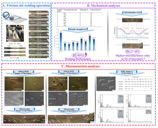
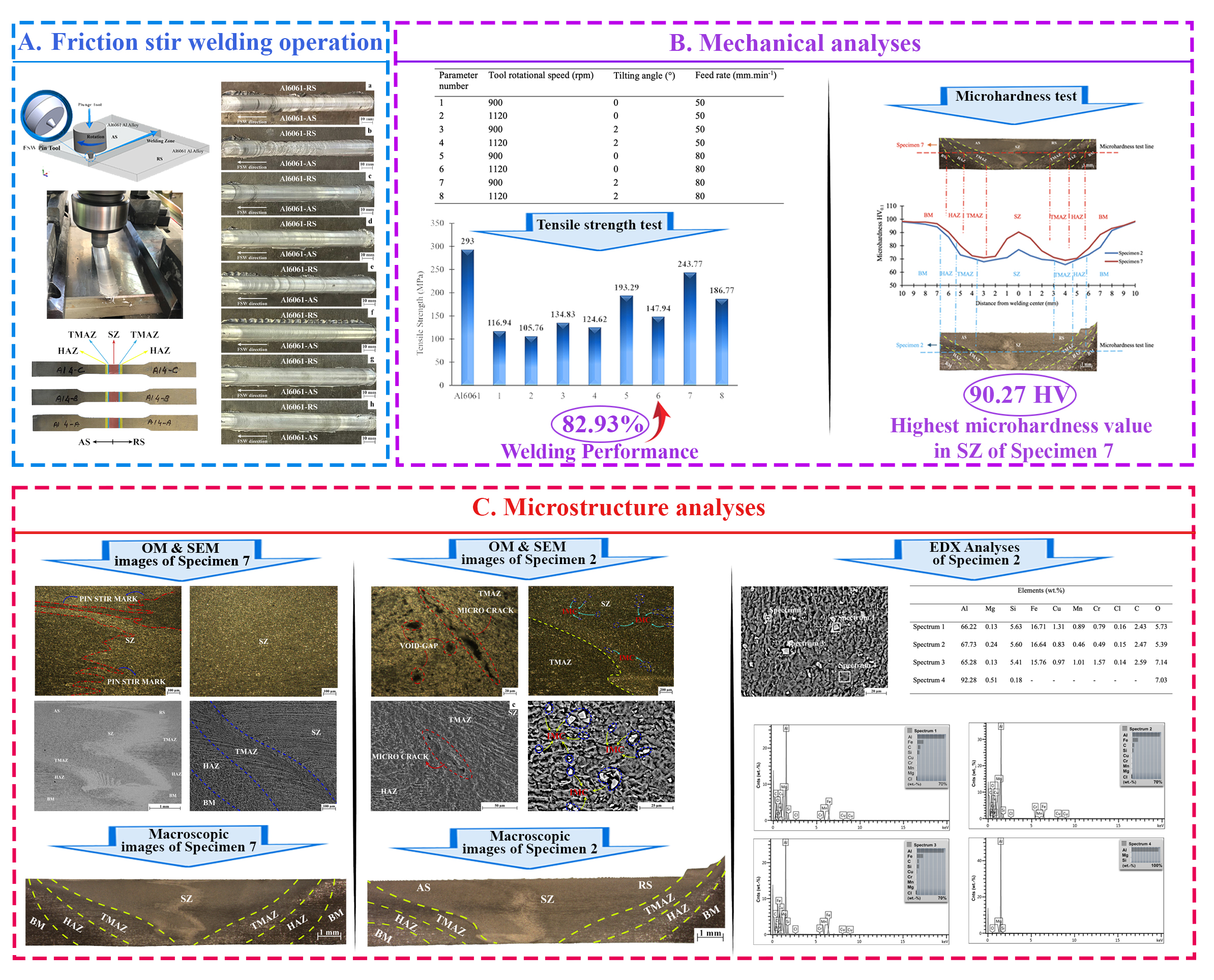
Graphical Abstract

1. Introduction

Friction stir welding (FSW), which was developed by The Welding Institute in 1991, is a solid-state welding method [1,2]. Shortened welding time, automation convenience, high welding strength values, and obtaining smooth weld surfaces are advantages of FSW. Furthermore FSW needs no additional weld metal and protective gas [3,4]. Materials joined by FSW are welded by extruding and plastically deforming before they reach their melting point. The heat generated during FSW occurs during friction between the tool and the material [5]. FSW can be utilized as a recent solution to welding high-strength alloys such as 2XXX, 6XXX, and 7XXX series aluminum alloys, which are typically non-weldable with conventional fusion welding due to low microstructure quality and abundant porosity [6,7,8,9].
Today, with the world’s existing resources dwindling, energy conservation, reduction of emissions, and environmental protection are important. Aluminum alloys are an ideal material to achieve this goal due to their advantage of being lightweight but high-strength. 6XXX aluminum alloys are known for their good mechanical and metallurgical properties, such as low density, good corrosion resistance, and ductility [10,11]. Al6061 alloys are widely used as structural materials for the automotive industry, aerospace industry, railway vehicles, and shipbuilding [12]. Al6061 alloys are used in the automotive industry for making wheel rims, wheel spacers, truck bodies, car frames, and fuel tanks. Al 6061 alloys are widely used in aerospace industry applications such as aircraft fuselages, aircraft wings, landing ladders, service systems, engine cowlings, electronic equipment enclosures, helicopter fuselage cladding, spacecraft, fuel tanks, and launch systems. They are used in the railway sectors for making container bodies, goods wagons, carriages, and trams. And they are also used in shipbuilding and the construction of helicopter platforms [13].
Recently, several researchers investigated the effect of tool rotational speed and feed rate on the microstructure and mechanical properties of 7075 and 6061 aluminum alloy welded by FSW [14]. Tensile tests of welded joinings show that the ultimate tensile strength 226.8 MPa was observed at 800 rpm tool rotational speed parameter and 160 mm.min−1 feed rate parameter. Insitu digital image correlation (DIC) and electron backscatter diffraction (EBSD) tensile test results indicated that the welded specimens fractured in the stir zone (SZ) and the thermo-mechanically affected zone (TMAZ) on the Al6061 alloy side due to their high dislocation density and significant plastic deformation. When the feed rate was increased, heat input was decreased; thus, the dislocation density in the Al6061 TMAZ was significantly increased, and the fracture location was shifted to this region. Furthermore, certain researchers studied the effect of the sheet positioning for dissimilar FSW of DH36 Steel and Al6061 alloy [15]. The microstructural study showed that significant grain refinement and grain elongation occurred in th SZ and TMAZ, respectively. According to Energy Dispersive X-ray Spectroscopy (EDS) analysis results, intermetallic compounds (IMCs) such as Al3Fe, AlFe, Al2Fe, and Al5Fe2 are thought to be present in the welded joints. The highest tensile strength was obtained from welded joints by placing the AA6061 at the retreating side (RS) and DH36 steel at the AS.
The effect of tool pin geometry on FSW dissimilar aluminum alloys AA5083 and AA6061 was investigated by some researchers [16]. Various tool shapes (square, cylindrical with thread, and tapered with thread) were used in the joints during the FSW. The specimens were welded by FSW at tool rotational speeds of 710 rpm, 900 rpm, and 1400 rpm with feed rates of 60, 31.5, and 40 mm.min−1. The experimental results show that good joints were obtained at a 900 rpm tool rotation speed and a feed rate of 40 mm.min−1. The highest welding strength (191.2 MPa) was obtained from these parameters by utilizing a strung apparatus pin profile. In another investigation, the thermal-assisted friction stir lap welding (FSLW) for dissimilar materials of 6061-T6 Al alloy and thermoplastic polycarbonate was studied [17]. Specimens were joined by FSLW with and without thermal assist. The welding results demonstrated that the thermal-assisted FSLW showed the formation of a better surface appearance at 140 °C. The highest tensile strength (34 MPa) was obtained at an assisted temperature of 120 °C. Some researchers investigated the effect of welding parameters on the microstructure and mechanical properties of FSW of Al6061 aluminum alloy joints [18]. Welding was performed at a constant feed rate of 760 mm.min−1 and tool rotational speeds of 950 and 1100 rpm. Results demonstrated that the better weld properties are found at 950 rpm, and 3 weld passes. The highest microhardness (85 HV) was obtained from specimens welded at 950 rpm, and 3 weld passes. And also hard precipitates of Al2O3 were reported. Effects of tool structure and process parameters in FSW on the temperature and mechanical properties of dissimilar copper–aluminium welded joints were investigated by several researchers [19]. 3 mm-thick 6061-T6 aluminium alloy and T2 pure copper plates, which were used in the study, were joined with FSW at different welding parameters and tool structures. The experimental results showed that the heat input increased as the shoulder diameter and pin diameter increased. The temperature of the weld seam increased by 30° with every 2 mm increase in the shoulder diameter and proportionally with the increase in the pin diameter. It was observed that the feed rate was more effective on the heat input than the tool rotational speed. When the threaded tool was used during the welding process, an increase in the Al2Cu phases was observed, and as a result, the tensile test strength increased from 183 MPa to 236 MPa.
Today, Al6061 alloys are widely used as structural materials in the automotive industry, aerospace industry, railway vehicles, and shipbuilding industry, due to their good properties. There are problems such as porosity, low microstructure quality joining high-strength Al6061 alloys with conventional fusion welding. FSW can be a good method for solving the problems of the Al6061 alloy. The welding parameters, which tool rotational speed, feed rate, and tilting angle, significantly affect the microstructure and mechanical properties of FSW joints of Al6061 alloys. Therefore, Al6061 plates were welded through the FSW method at different feed rates, different tool rotational speeds, and different tilting angles in this study, to investigate the microstructure and mechanical properties of welded joints. In this study, the effect of welding parameters on the mechanical and microstructural properties of Al6061 alloy joined by FSW was investigated, and the best combination of FSW parameters that provide the highest weld strength were determined.
Although FSW of aluminum alloys has been investigated in previous studies, the reported results show that weld quality is highly dependent on the selected process parameters. Variations in tool rotational speed, feed rate, and tilting angle can significantly influence microstructure and metallurgical properties of welded joints. Therefore, experimental studies are still required to improve the understanding of the effect of welding parameters on microstructural evolution and mechanical behavior in FSW of Al6061 alloy. In this context, the present study investigates the effect of selected welding parameter combinations (feed rate, tool rotational speed, and tilting angle) on the microstructure, hardness distribution, and tensile properties of Al6061 FSW joints and provides additional experimental data.

2. Materials and Methods

In this study, Al6061 plates with dimensions of 3 mm × 100 mm × 150 mm were used. The nominal chemical compositions and mechanical properties of Al6061 alloy (provided by Güray Aluminum Marketing Industry Trade Ltd. Co., Istanbul, Turkey) are introduced in Table 1 and Table 2, respectively.
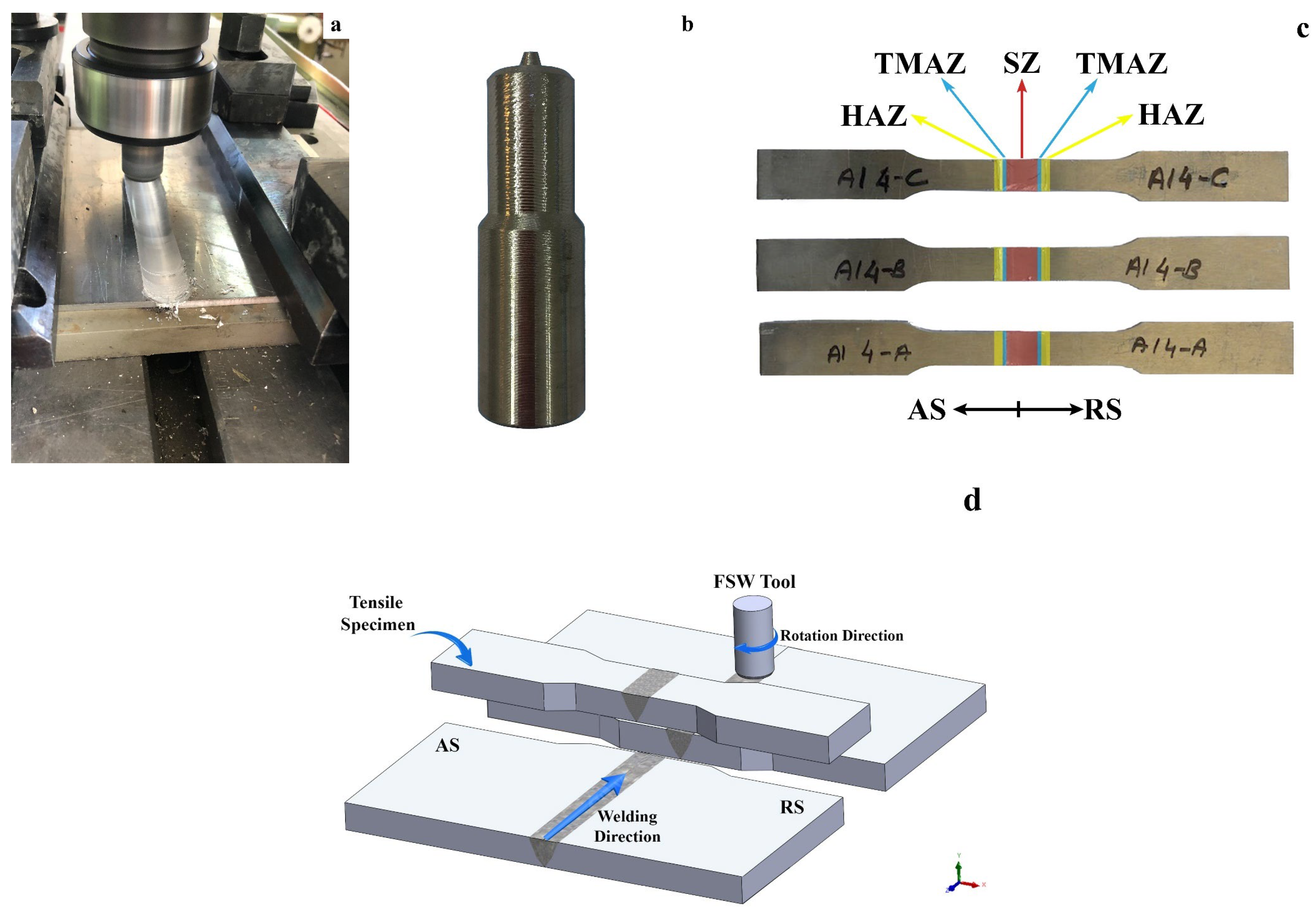
The surface oxides of the plates were removed with a steel brush, and then the surface of the plates was cleaned using pure alcohol before FSW. Al6061 plates were butt-welded by the FSW method with a weld direction perpendicular to the rolling direction. The welding operation was performed in the Taksan FU 315 × 1250 Universal Milling Machine located in the Laboratory of the Mechanical Department, Balıkesir Vocational School, Balıkesir University (manufactured by Taksan Machine Tools Industry and Trade Inc., Kayseri, Turkey). Figure 1a shows the image of the FSW operation. The waiting time at the start of welding was taken as 30 s, and the tool rotated in a clockwise direction in the FSW process.
A tapered pin tool was used in the research. This tool was made of 1.3343 high-speed steel, and it has a microhardness of 62 HRC through heat treatment. The tool shoulder had a flat geometry with a diameter of 12 mm. Scrolls, grooves, or surface features were not machined on the shoulder surface. The shoulder was designed to provide frictional heating and forging action during the welding process. Plunge depth of the shoulder was 0.12 mm. A steady axial force of 7 KN had been applied for all FSW joints. The pin surface geometry was flat. Pin depth was 2.85 mm. The outer diameter of the tapered pin was 3 mm, and the inner diameter was 1.5 mm. Figure 1b shows the image of the tapered pin tool. Table 3 presents the welding parameters, which were selected based on preliminary experiments in the experiments. In the coding of the welding parameters, the values of tool rotational speed, tilting angle, and feed rate were used as 900/0/50, respectively.
After the FSW operation, tensile test was performed on the welded joints. The tensile tests were performed using the Zwick Roell tensile testing machine (ZwickRoell Group, Ulm, Germany) located in the Science and Technology Application and Research Centre at Balıkesir University. For all conditions, three tensile specimens were prepared with the weld seam in the middle and in accordance with the ASTM E8-04 standard [20]. The drawing speed of the tensile test was determined 2 mm.min−1 at all the tensile tests and the tensile strength of specimens were measured perpendicular to the welding direction. The images of tensile test specimens are shown in Figure 1c.
The microhardness values of the welded specimens were measured using the Shimadzu HMV microhardness tester (Shimadzu Corporation., Kyto, Japan) at the Metallurgical and Materials Engineering Laboratory of 9 Eylül University. The measurements were taken along a line perpendicular to the direction of the weld seam, at 1 mm intervals from the middle of the plate thickness and on the weld surface, on the Vickers scale (HV0.1). The measurements were performed under a load of 0.1 kg and a holding time of 15 s.
For the microscopic examinations, welded specimens with a cross-section perpendicular to the weld direction were inserted in the bakelite mold. The weld cross-sections of specimens were sanded with sandpaper of 220 to 1200 grit, and they were polished with 3 μm and 1 μm diamond paste. And then specimens were etched with Poulton reagent (50 mL Poulton solution + 25 mL concentrated HNO3 + 40 mL chromic acid solution) for 30 s. The microstructure of welded specimens was observed by using an optical microscope (OM) (Nikon DS-Fi1 (Nikon, Tokyo, Japan) located at Metallurgical and Materials Engineering Laboratory of 9 Eylül University, Turkey) and scanning electron microscope(SEM) (FEI QUANTA 250 FEG (FEI Company, Hillsboro, OR, USA)). And the localized chemical composition of the weld zone was determined by energy-dispersive X-ray spectroscopy (EDX) analyses.

3. Results and Discussion

3.1. Weld Appearances

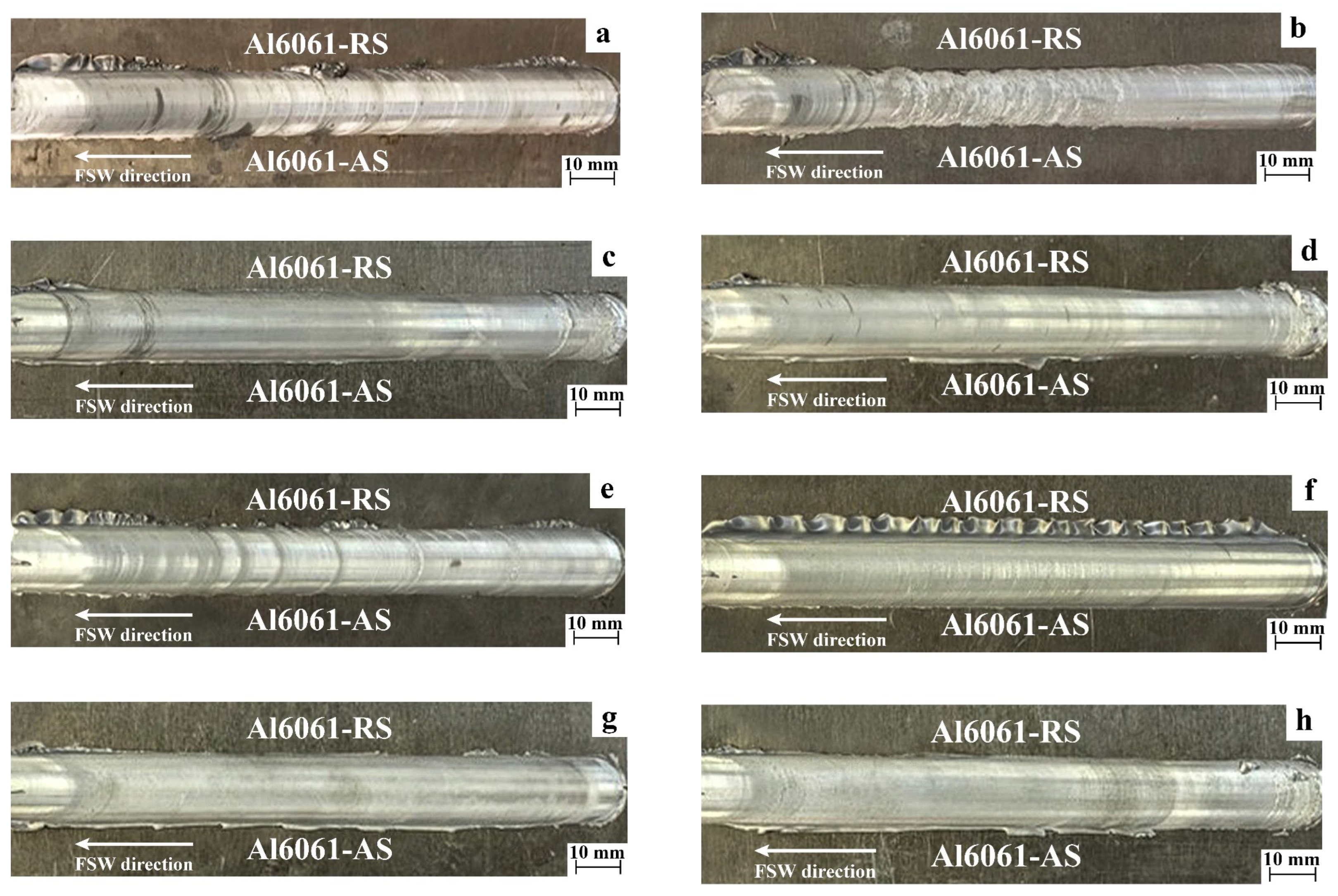
In this study, Al6061 alloy was successfully welded by FSW. Figure 2a–h show the surface images of the welded specimens.
Flash formation is observed in the weld edges of the retreating side in the welding area, Figure 2a, Figure 2b, Figure 2e and Figure 2f, which show Specimens 1, 2, 5 and 6, respectively. These specimens were welded without a tilting angle. When welding is performed without a tilting angle, the friction surface area between the shoulder and the material increases. However, this situation makes it difficult for sufficient plasticised material to accumulate in the area behind the pin to produce a forging effect. To maintain the vertical seam pressure required for a successful weld, the tool plunge force that the machine must apply increases. The inability to properly orient the material reduces the pressure behind the pin. It is thought that this pressure loss and the high tool plunge force applied to achieve the required penetration may have led to the deformed material protruding from the shoulder edge and excessive flash formation on the weld surface.
Furthermore, when Figure 2a, Figure 2b, Figure 2e and Figure 2f are examined, an irregular onion ring appearance is observed in the weld zone of Specimens 1, 2, 5 and 6, respectively. In the FSW process, the tilting angle ensures the smooth and homogeneous transport of material backwards, supporting the formation of regular onion rings in the weld zone. It is thought that welding these specimens without a tilting angle contributed to the irregular onion ring appearance in the weld zones. Furthermore, uneven micro-relief is observed in Figure 2b, which shows Specimen 2, in the weld zone. This is thought to be because Specimen 2 was joined at a high tool rotational speed and a low feed rate without a tilting angle.

3.2. Mechanical Properties

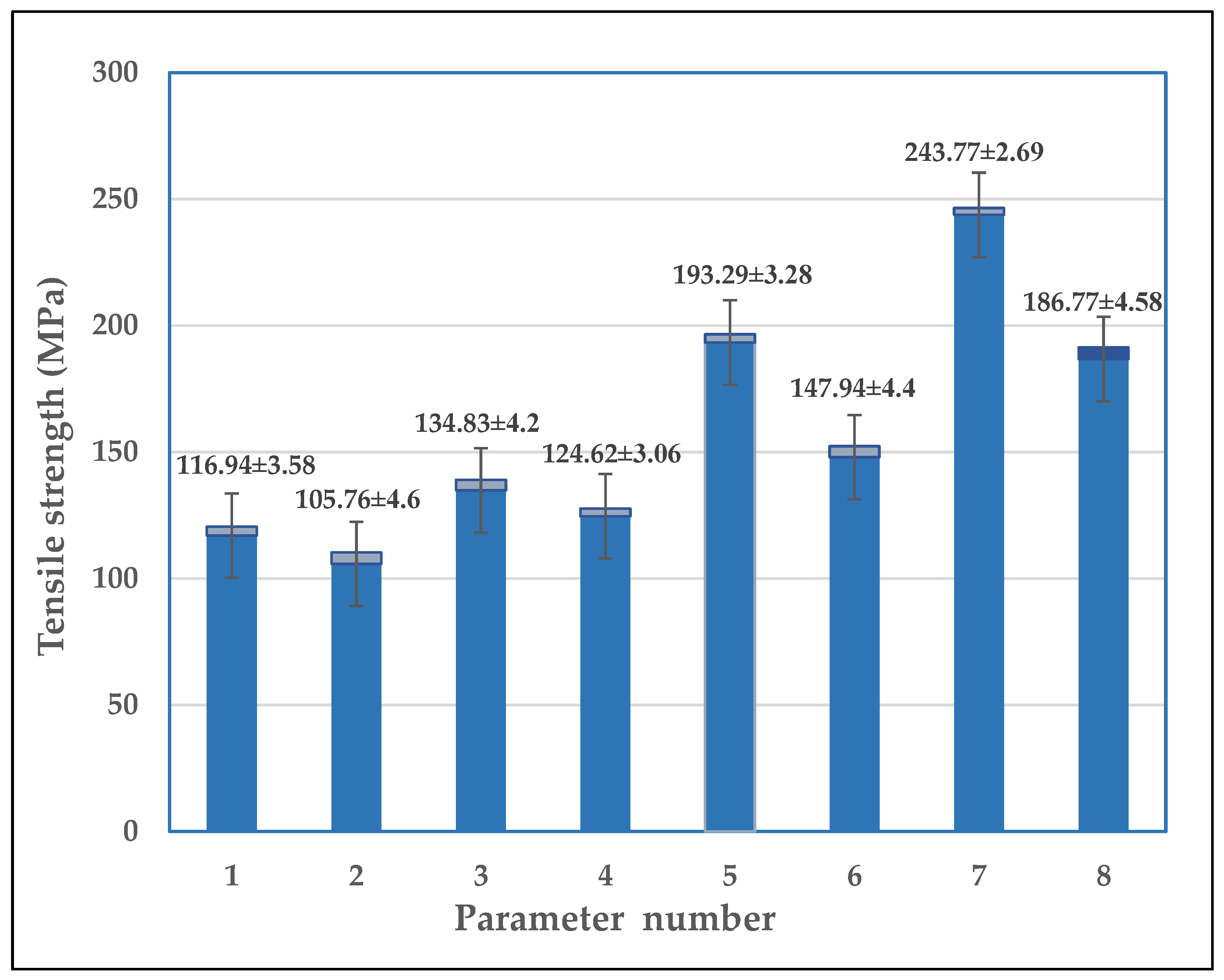
Figure 3 shows the tensile strength values of the welded specimens and Al6061 base material (BM).
Specimen 1 (900/0/50) showed 116.94 MPa welding strength. Specimen 2 (1120/0/50) showed the lowest welding strength (105.76 MPa) of all welding specimens. It is thought that due to the absence of a tilting angle and also using high tool rotational speed and low feed rate, the welding strength value of Specimen 2 was decreased. Specimen 3’s (900/2/50) welding strength was 134.83 MPa. Also Specimen 4’s (1120/2/50) welding strength was 124.62 MPa. Specimens 1, 2, 3, and 4 were joined at 50 mm.min−1 feed rate. Specimen 1’s and 2’s welding strength values were lower than Specimen 3’s and 4’s. Specimens 1 and 2 joined without tilting angle. Specimens 3 and 4 joined at 2° tilting angle. Specimen 1 and Specimen 3 were joined at 900 rpm tool rotational speed. Specimen 2 and Specimen 4 were joined at 1120 rpm tool rotational speed.
Specimen 5 (900/0/80) showed 193.29 MPa welding strength. Specimen 6 (1120/0/80) showed a lower welding strength (147.94 MPa) than Specimen 5. According to the tensile strength test results, as Specimen 7 (900/2/80) showed the highest welding strength (243.77) of all welded specimens. Also, Specimen 8’s (1120/2/80) welding strength was 186.77 MPa. Specimens 5, 6, 7, and 8 were joined at 80 mm.min−1 feed rate. Specimens 5 and 6 joined without tilting angle. Specimens 7 and 8 joined at 2° tilting angle. Specimen 5 and Specimen 7 were joined at 900 rpm tool rotational speed. Specimen 6 and Specimen 8 were joined at 1120 rpm tool rotational speed. Specimen 5’s welding strength was lower than Specimen 7’s, and Specimen 6’s welding strength was lower than Specimen 8’s welding strength.
When the tilting angle was not used during the FSW process, the welding strength of the specimens decreased. In the literature, it was noted that the tilting angle significantly affected the mechanical properties of the joining by the FSW process. And the mechanical properties of the joints prepared using the tilting angle during the FSW process were better than those of the joints prepared without using the tilting angle [3,4,21,22,23,24]. In this study, the tensile test results of Al6061 alloy joined with FSW at the same feed rate and tool rotational speed showed that the tensile test values obtained when 0° tilting angle was used were lower than those obtained when a 2° tilting angle was used.
According to the tensile test results, it is seen that the welding strengths of Specimens 5, 6, 7, 8 which were joined at feed rate of 80 mm.min−1, are higher than the welding strength of Specimens 1, 2, 3, 4. It was determined that Specimens 1, 2, 3, 4, welding strength values, which were joined at 50 mm.min−1 feed rate, decreased. When the feed rate increased to 80 mm.min−1, the welding strength of the specimens increased.
Heat input is essential for FSW operation because it has a major effect in controlling the welded joint’s properties and quality. Welding parameters control the heat input in the welding zone during the FSW operation. Tool rotational speed and feed rate designate the amount of frictional heat generated, followed by plastic deformation and deformation heat. Thus, choosing the suitable combination of those parameters is important for a defect-free joint with a quality metallurgical bond and mechanical properties [3,4,13].
The feed rate controls the thermal cycle, residual stresses, and welding production rate. According to the tensile test results, when the feed rate was increased during FSW operation welding strength value of the specimens was increased. It was seen that the best feed rate value was 80 mm.min−1 during the FSW operation in the study. Tool rotational speed affects the density of plastic deformation occurring in the weld zone during the FSW operation, and thus, this affects material mixing. High tool rotational speed with the redundant free-of-stirred material on the top surface leads to macroscopic defects, such as poor surface (flash), voids-gap, porosity, tunneling, or wormhole formation. The high rotational speed causes extremely high heat input. Also, the low tool rotational speed leads to poor stirring of the material and low heat input. When the tool rotational speed was increased during FSW operation welding strength value of the specimens decreased. During the FSW operation, choosing middle amounts of heat input is suitable for plastic deformation, stirring, material flow, and consequently quality joining [3,13,25,26].
During the joining with FSW of Al6061 alloy, AlFeSi, Fe3SiAl12, and Mg2Si IMC occur. The IMC have a needle shape, and they lead to the loss of tensile strength of welded specimens. Because the IMC peaked at a high tool rotational speed, the welding strength of the specimens welded under a tool rotational speed of 1120 rpm was decreased in this study [23,25,27,28,29].
Also in this study, it was seen that the welding strength of specimens joined with FSW at high tool rotation speed (1120 rpm) and low feed rate (50 mm.min−1) are the lowest value. Generally, a high tool rotational speed often causes increased stirring per unit time, while a low feed rate causes increased stirring per unit length of workpiece. A combination of high tool rotational speed and low feed rate brings about increased stirring of a unit length of workpiece per unit time. Therefore, large frictional heat is generated per unit time, and the plastic deformation is very severe, leading to a high degree of dynamic recrystallization. Hence, substantial grain refinement is achieved, and the mechanical properties of the weld joints of Al alloys are improved. In case of FSW of Al6061, care must be taken because excessive heat generation will cause the dissolution of the strengthening precipitates, which is the major strengthening mechanism in the alloy. Due to this, parameters such as tool rotational speed and feed rate should be well-adjusted so that the dissolution of the strengthening precipitates (i.e., the softening effect) is minimized while still achieving grain refinement. In this research, experimental studies determined the suitable combination of FSW parameters, resulting in significant improvements in the microhardness and tensile strength of weld joints [30,31,32].
After FSW, the internal structure formed in the weld zone is examined in three regions according to the structure of the grains and precipitation phases. These regions are classified as SZ, TMAZ, and the heat-influenced zone (HAZ). The SZ is a region that undergoes intense plastic deformation and experiences high friction temperatures during the welding process. The SZ is defined as the “dynamically recrystallizing zone” or “weld center.” Dislocation density is lower in the SZ, and the grains are finer and more oriented. TMAZ is located between the SZ and HAZ, and is subject to high deformation and temperature. In the TMAZ, intense forging occurs as the grains of the base metal are extruded from the weld center into this region. The heat generated during FSW alters the microstructure and mechanical properties of this region, causing the deformed grains to become elongated and flattened. HAZ is closer to the weld metal and adjacent to the BM. The material in this region is affected by the heat generated during mixing, resulting in partial changes in the material’s structure and properties. Plastic deformation does not occur in this region. The grains in this region exhibit properties very similar to those of the BM [3,4,13,31,32,33,34,35,36,37,38].
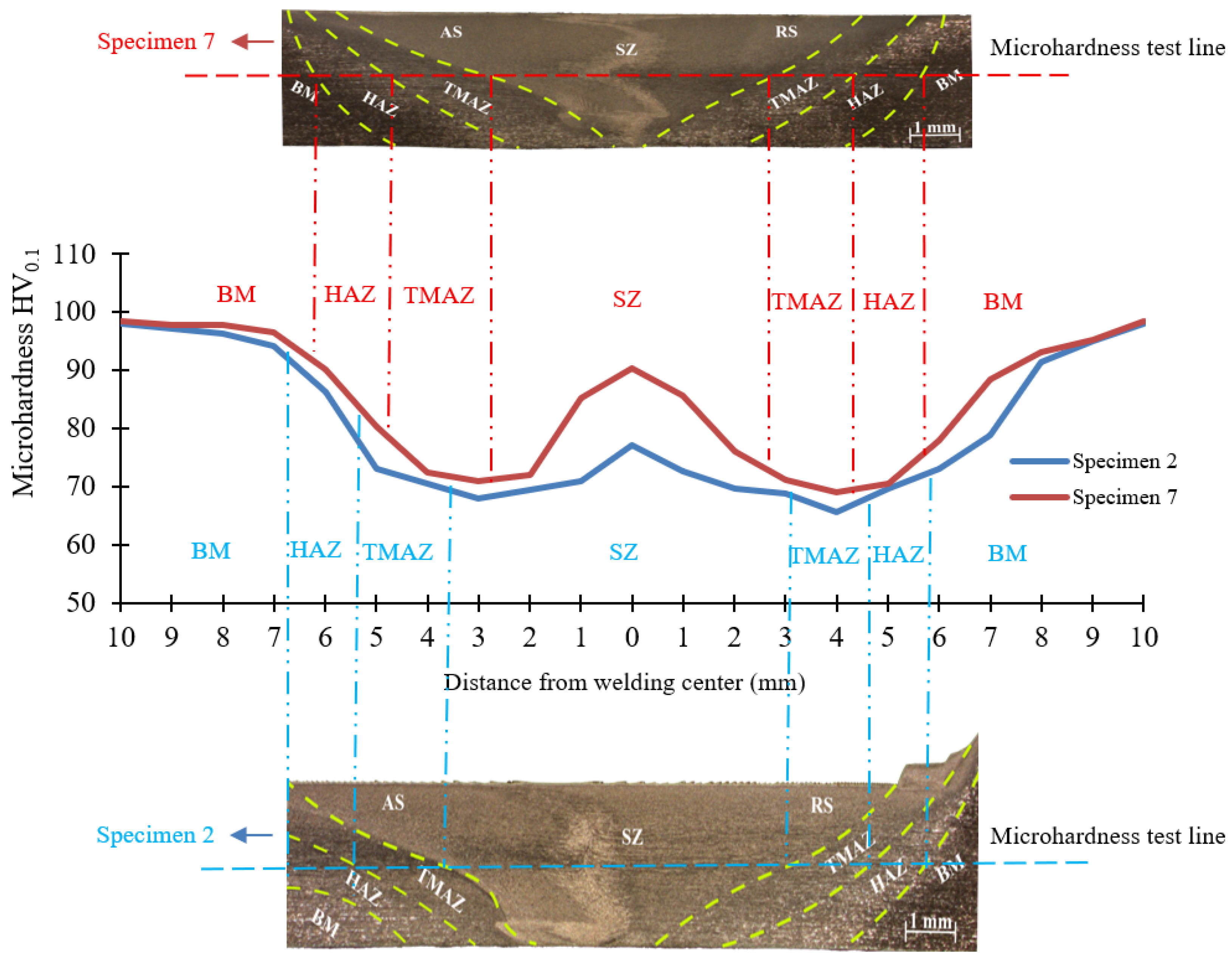
In addition, as shown in Figure 4, the microhardness values in the weld zone of the specimens with the highest (Specimen 7) and lowest (Specimen 2) welding strength were determined. In particular, the microhardness values were measured in the cross-section of the Specimens 7 and 2. Microhardness distribution for specimens hold a W-shape pattern consistently over distances from weld center line. In previous studies of aluminum welding, it was stated by the authors that there was similur pattern. Specimen 7 achieved the highest microhardness value of 90.27 HV, and Specimen 2 achieved the lowest microhardness value of 77.05 HV in SZ.
Minimum microhardness values are observed in HAZ and TMAZ. Since these regions are exposed to heat and plastic deformation, they can generally reduce hardness while promoting healing processes and the coarsening or dissolution of precipitated particles. In SZ, however, the microhardness value increases due to the intense deformation and material mixing that occurs during the welding process. This promotes the formation of a finer microstructure in SZ through dynamic recrystallization. The tensile strength of the joints is closely related to the microhardness variations in the weld zone, as regions with lower microhardness are more susceptible to local deformation during tensile loading. Therefore, the measured W hardness profile is considered to be consistent with the microstructural characteristics observed in different weld zones.
Specimen 2 was welded without using a tilting angle, with low feed rate (50 mm.min−1) and high tool rotational speed (1120 rpm) parameters. In FSW, the combination of high tool rotational speed and low feed rate parameters causes good stirring of the material during welding; therefore, a large amount of heat is generated in the weld zone. Since the plastic deformation caused by the welding heat is very high, it leads to a high degree of dynamic recrystallization and dissolution of the reinforcing solutions in the material, which can causes a decrease in the microhardness of the SZ. It is thought that this can be the reason for the decrease in microhardness in the SZ of Specimen 2. If appropriate tool rotational speeds and feed rates are selected, the dissolution of reinforcing precipitates (i.e., the softening effect) can be minimized while maintaining the beneficial effect of grain refinement. Microhardness measurements of Specimen 7, welded with a tilting angle of 2°, a tool rotational speed of 900 rpm, and a feed rate of 80 mm.min−1, revealed the highest microhardness value in the SZ. In FSW processes, selecting the parameters that provide the best welded joints is crucial. When FSW parameters are properly adjusted, significant improvements in the microhardness and tensile strength of welded joints are achieved compared to the BM [3,4,13,35,36]. In this study, according to the tensile test and microhardness measurement results, the best parameter combination that the highest welding strength and best microhardness values was a tool rotational speed of 900 rpm, a tilting angle of 2°, and a feed rate of 80 mm.min−1.

3.3. Microstructure and Phase Analysis

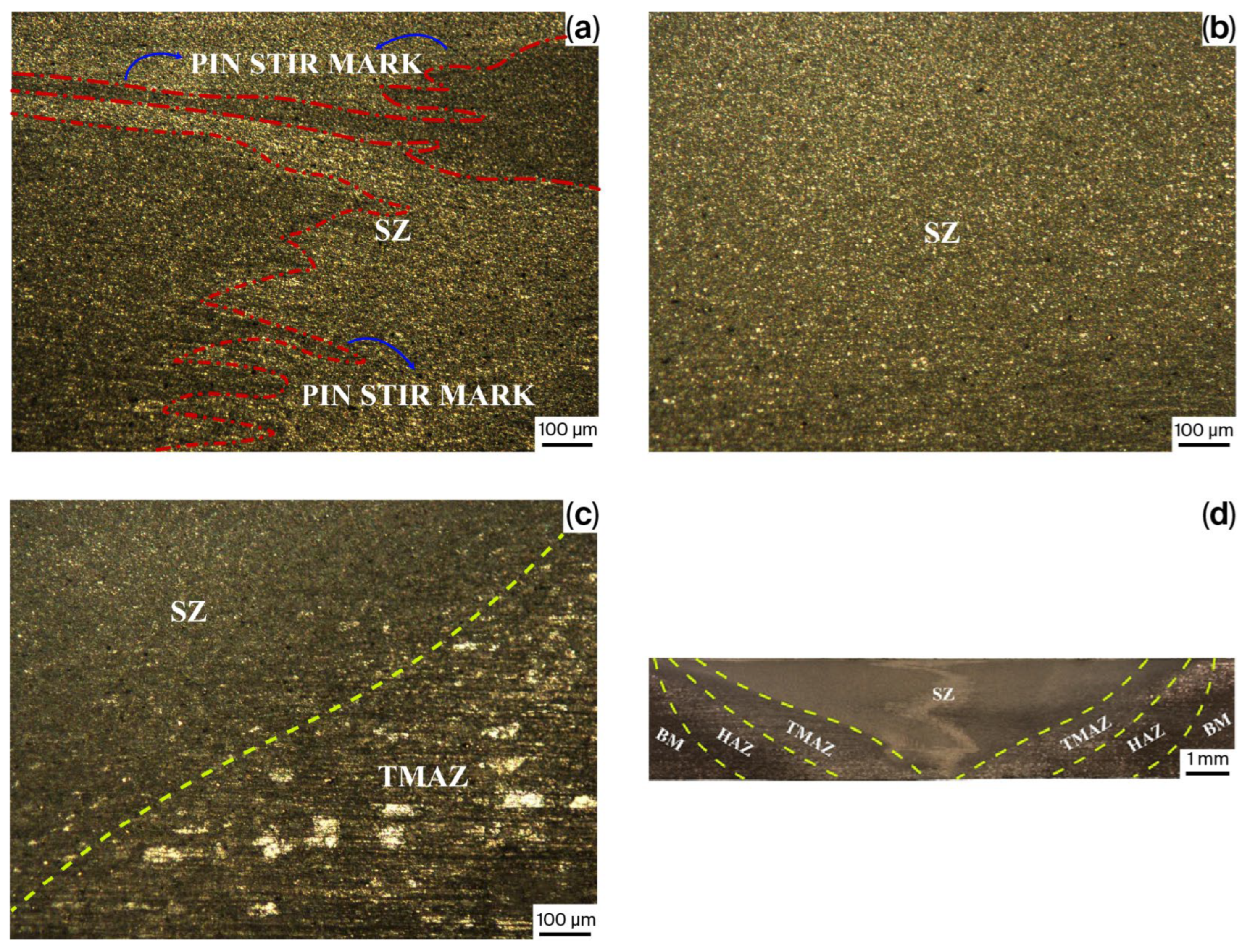
Figure 5a–c show OM images and of the Specimen 7’s welding zone, Figure 5d shows a macroscopic image of the weld zone. Figure 5a shows that the stir mark on the pin and the mixing in the welding area were successful and uniform. Figure 5b shows the fine-grained structure in SZ. Figure 5c shows the fine-grained structure in SZ and the elongated and oriented grain structure in TMAZ.
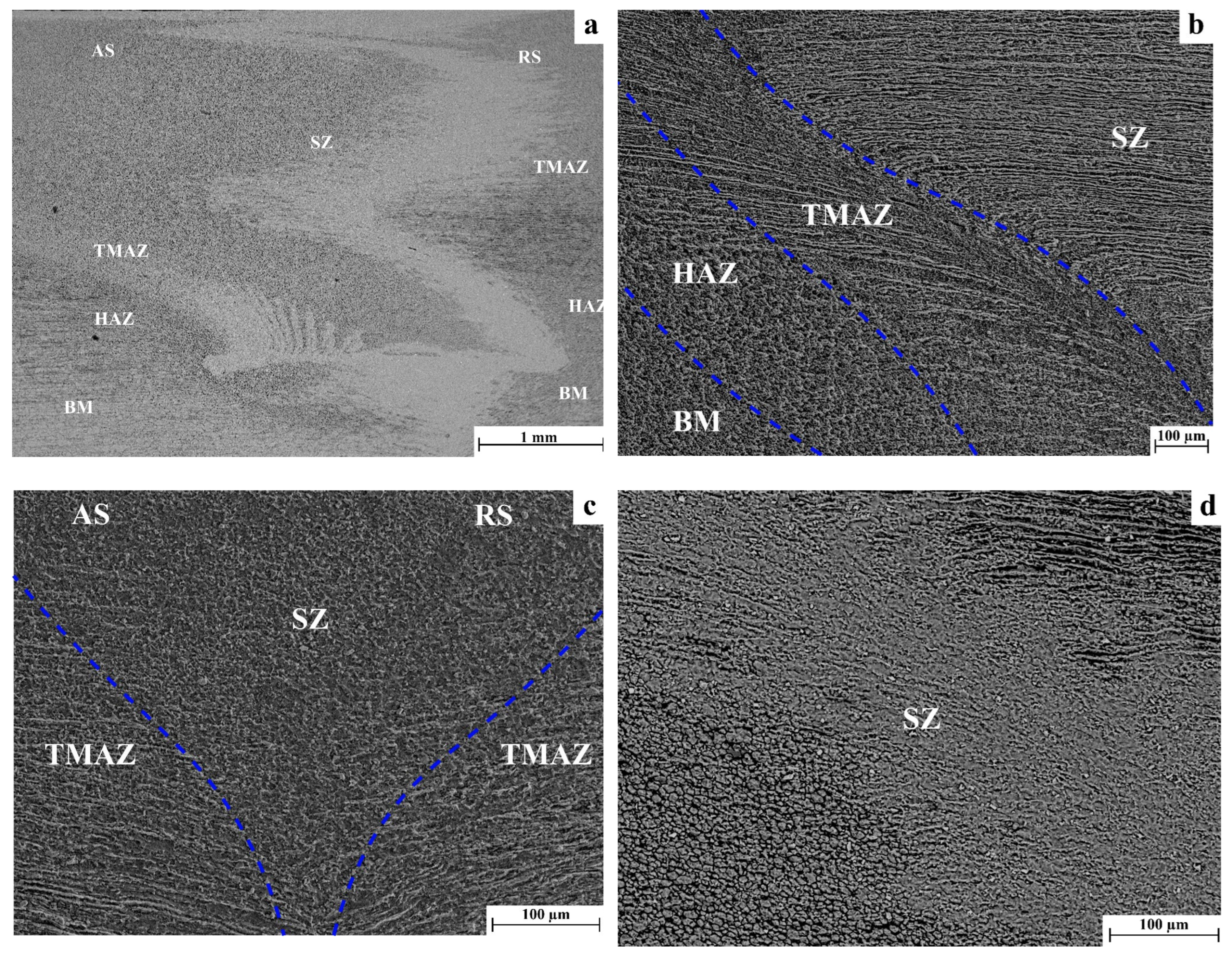
Figure 6a–d show SEM images of Specimen 7. Investigation of the macro, OM, and SEM images of Specimen 7 reveals that the Al6061 alloy were successfully joined by FSW. Mixing occurred uniformly in the weld zone, and no errors, voids, or defects were observed. Welding parameters directly affect weld quality and welding strength. The 900 rpm tool rotational speed and 80 mm.min−1 feed rate parameters increased the heat generated during the welding process and the mixing effect of the pin. The 2° tilting angle parameter increased the extrusion degree, causing the material in the weld zone to become viscous. The deformation and extrusion density during the FSW process caused the grains to shrink in the SZ. OM images of Figure 5a–c and SEM images of Figure 6a–d fine-grained microstructure with a homogeneous distribution is observed in the SZ after mixing. In Figure 5c and Figure 6a–c, it is seen that the grains in the microstructure flatten and elongate in the TMAZ, which is subjected to high deformation and temperature. A microstructure close to the BM is observed in the HAZ region in Figure 6a,b.
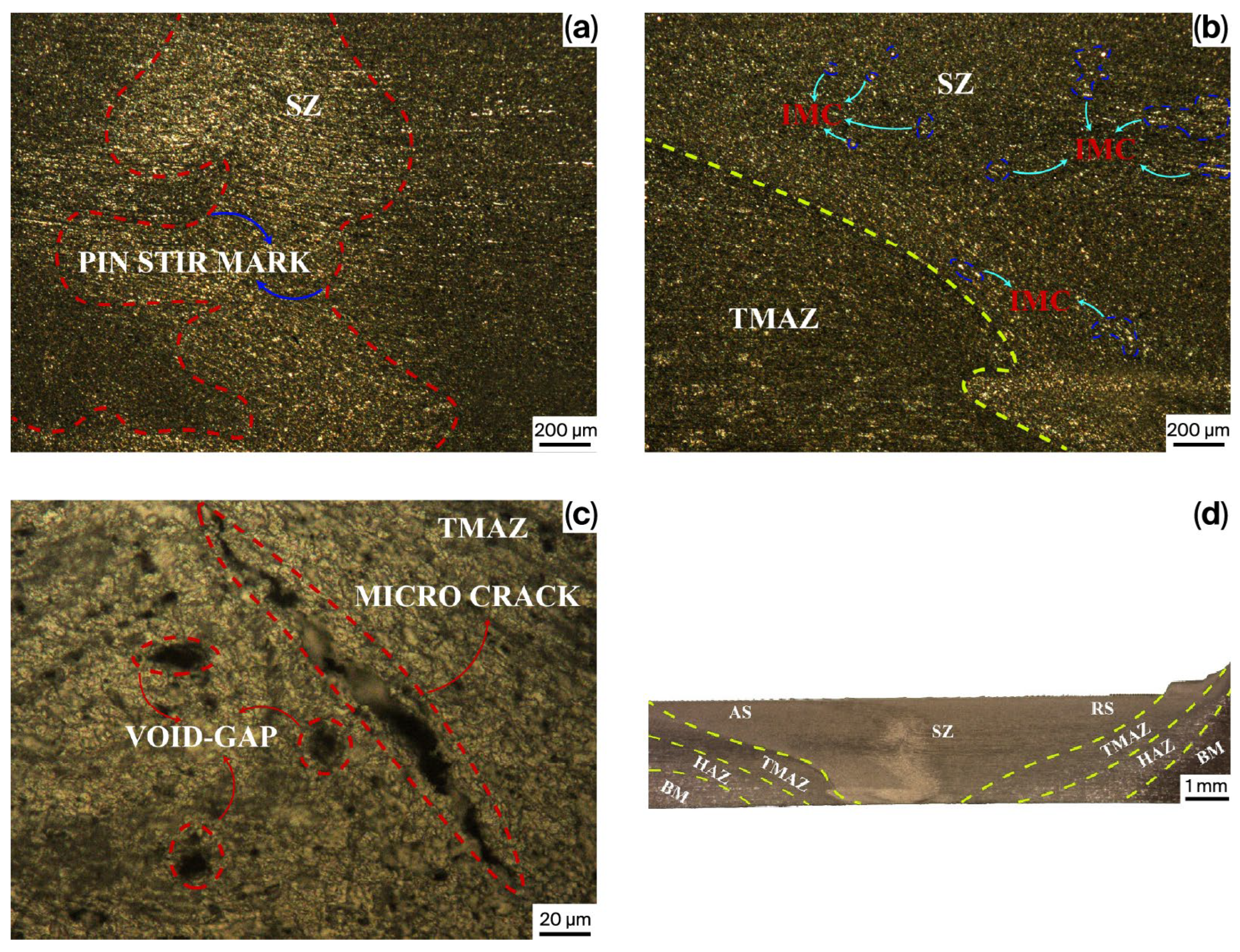
Figure 7a–c show OM images of the weld zone of Specimen 2, and Figure 7d shows a macro view of the weld zone of Specimen 2. Figure 7a shows that stirring in the weld region was not fully achieved. In Figure 7b, the white IMC formations in SZ are noteworthy. Figure 7c shows the microcracks and void-gap formations occurring in the TMAZ.
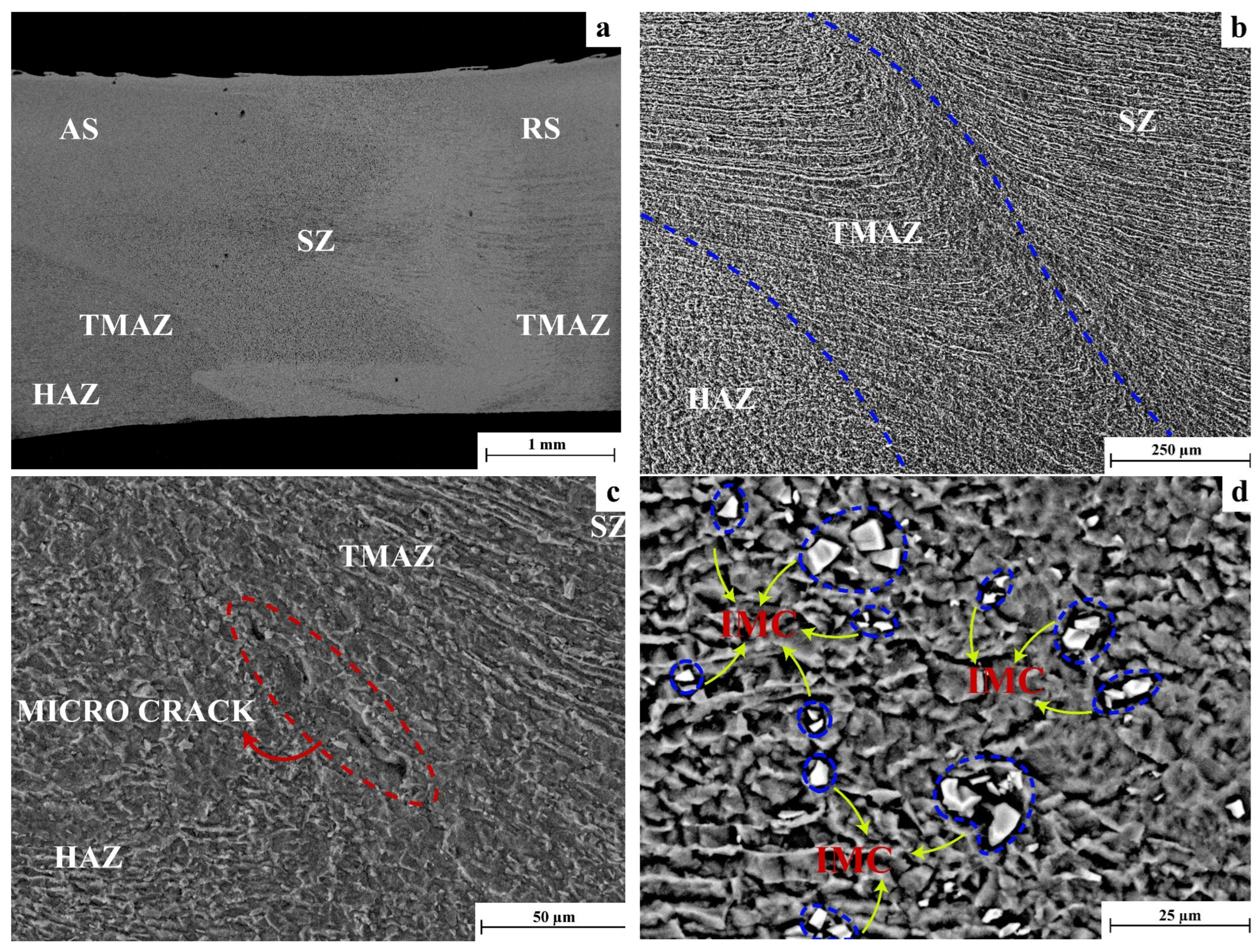
Figure 8a–d show SEM images of Specimen 2. Specimen 2 has the lowest welding strength according to the tensile test results in this study. Examination of the macroscopic, OM, and SEM images of Specimen 2 reveals that the two plates do not fully interlock in the weld zone, and mixing is not fully achieved. Furthermore, a void-gap defect is observed in the TMAZ. It is suggested that due to the combination of high tool rotational speed and low feed rate, a large amount of frictional heat is generated per unit time, leading to severe plastic deformation. It is thought that this can lead to a high degree of dynamic recrystallization, resulting in significant grain refinement and dissolution of reinforcing precipitates. It is thought that the excessive heat generated during the FSW process, performed at a high tool rotational speed of 1120 rpm and a low feed rate of 50 mm.min−1, causes the dissolution of the reinforcement precipitates, which are the main reinforcement mechanism in the alloy, and the emergence of Al-Fe-Si-rich intermetallic phase, which is thought to be Fe3SiAl12 IMC in the TMAZ. In Specimen 2, whose macroscopic image of the weld zone is given in Figure 7d and SEM images of the weld zone in Figure 8a,b, it can be seen that the two Al6061 plates joined by FSW in the weld zone are not fully interwoven, and mixing is not fully achieved. In the Figure 7c OM image and the Figure 8c SEM image of Specimen 2, a micro-crack and void-gap defect occurring in the TMAZ is observed. In the OM image in Figure 7b and the SEM image in Figure 8d, light-colored particles, Al-Fe-Si-rich intermetallic phase thought to be the Fe3SiAl12 IMC, are observed in the microstructure in the SZ of Specimen 2. It is thought that the void-gap defect in the TMAZ and the particles, thought to be an IMC in SZ, can cause the decrease in the weld strength of Specimen 2. EDX analysis results of Specimen 2 are presented in Table 4.
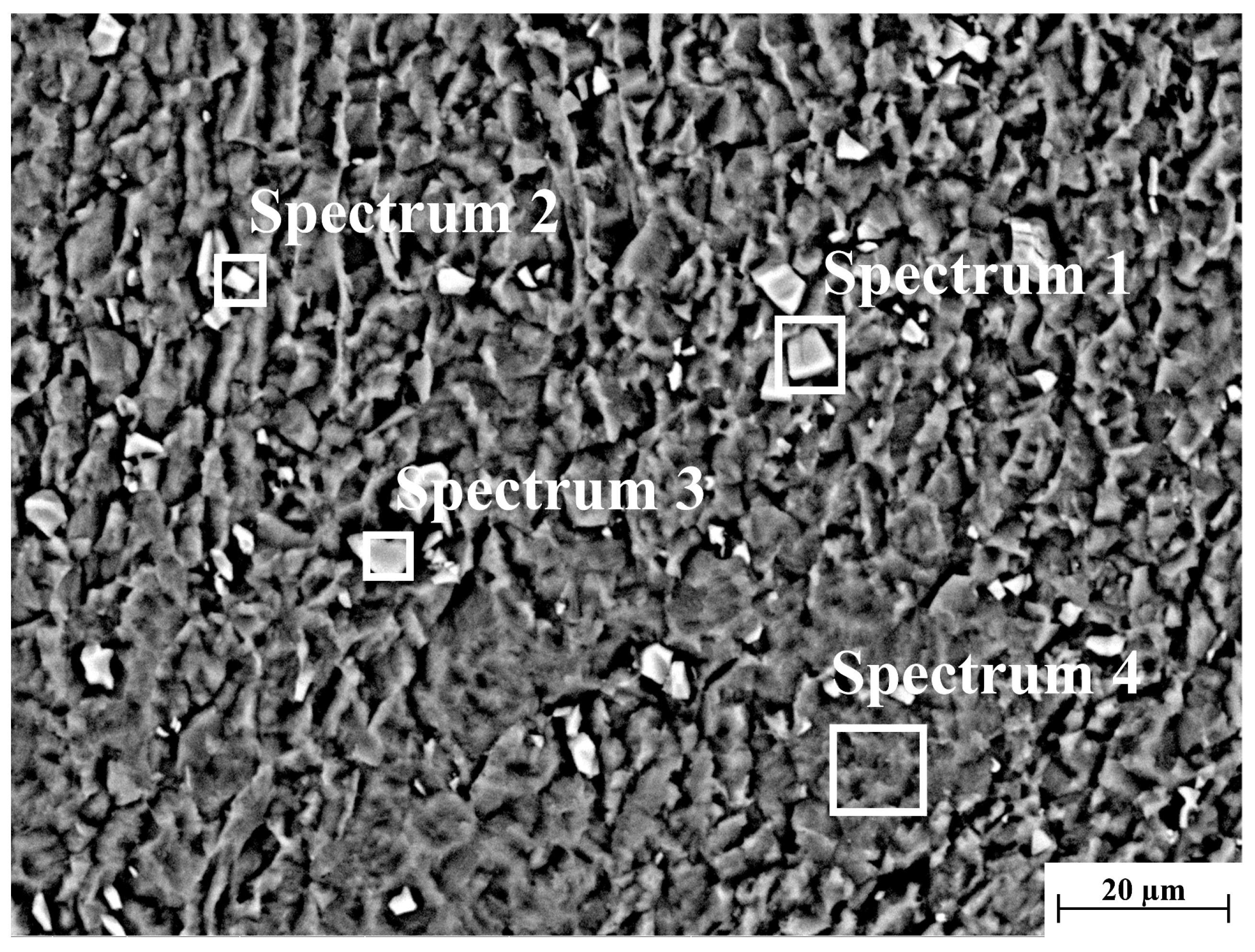
Figure 9 shows that Spectrums 1, 2, 3, and 4 in Specimen 2’s SZ. The wt wt% elemental analyses of Spectrums 1, 2, and 3 of Specimen 2 were taken from the SZ region, which is light-colored and thought to be an IMC.
It is suggest that the this IMC in the SZ reduced the welding strength of Specimen 2.
According to the EDX analysis results of Specimen 2, it is determined Al-Fe-Si-rich IMC which is thought to be Fe3SiAl12 IMC in the SZ (Figure 10a–c).
Table 4 shows that EDX analysis results of Specimen 2. When the element ratios in the Spectrum 1–3 results in Table 4 are examined, it is clearly determined that Specimen 2 has Al-Fe-Si-rich intermetallic phase IMC in the SZ of it.
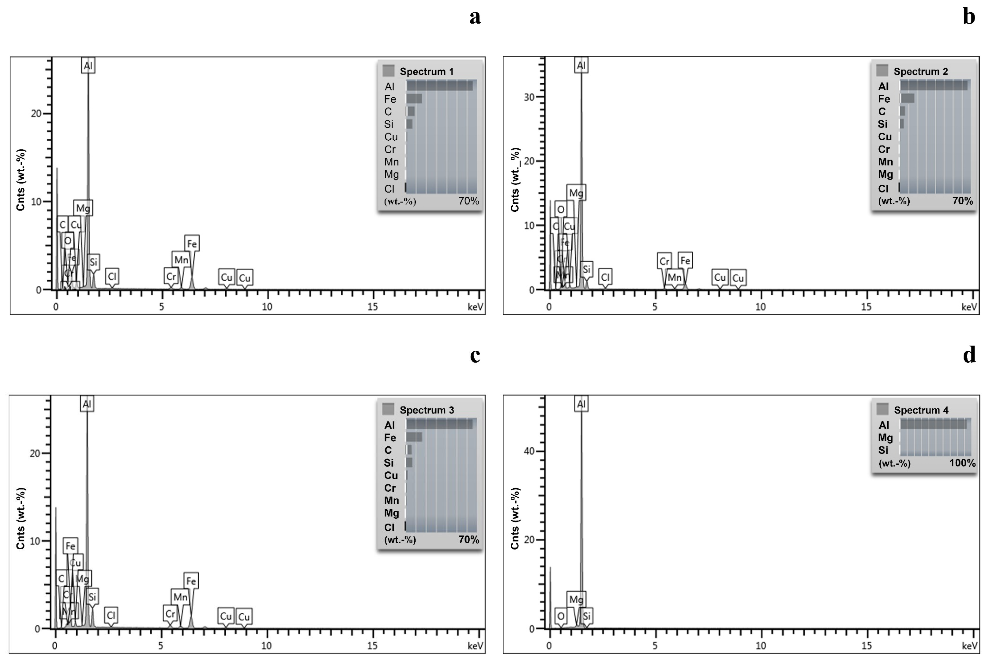
Table 4 shows the EDX analysis results of Specimen 2. Spectrum 1–3 is the EDX analysis performed on the light-colored regions in the SZ zone of Specimen 2, which are thought to be IMCs formation. When the element ratios in the spectrum 1–3 results in Table 4 are examined, it is clearly determined that Specimen 2 has Al-Fe-Si-rich IMC which is thought to be Fe3SiAl12 in its SZ. Figure 9 shows the SEM image of the SZ and Figure 10a–d show the results of the EDX analysis (wt,%), of Specimen 2, from Spectrum 1–4, respectively.
According to Table 4, elemental analysis results of Spectrums 1, 2, and 3, the high values of Fe and Si elements alongside the main compositional element Al, suggest that there may be an Al-Fe-Si rich IMC formation at these points. When the %wt elemental analysis of Spectrum 1 is examined, the values of 66.22% Al, 5.63% Si, and 16.71% Fe are noteworthy as they are quite high compared to the ratio of other elements. This analysis result is also given graphically in Figure 10a. In the %wt elemental analysis of Spectrum 2, 67.73% Al, 5.60% Si, and 16.64% Fe values were measured. This analysis result is given graphically in Figure 10b. In the %wt elemental analysis of Spectrum 3, 65.28% Al, 5.41% Si, and 15.76% Fe were measured. This analysis result is also presented graphically in Figure 10c. When the element ratios in the Spectrum 1–3 results in Table 4 and Figure 10a, b, c are examined, it is determined that Al-Fe-Si rich IMC, which can be thought of as Fe3SiAl12 IMC of Specimen 2’s SZ.
The %wt elemental analysis of Spectrum 4 was taken from the dark-colored SZ region of Specimen 2. The results showed 92.28% Al, 0.51% Mg, and 0.18% Si. The analysis results are presented graphically in Figure 10d. The percentage of other elements forming the Al 6061 alloy is very low and therefore could not be determined in the EDX measurement results.

4. Conclusions

In this study, 3 mm thick Al 6061 plates were joined using FSW at tool rotational speeds of 900 and 1120 rpm, feed rates of 50 and 80 mm.min−1, and tilting angles of 0° and 2°. This study aims to determine the best combination of FSW parameters under the present experimental conditions for joining Al6061 alloy with FSW, which is widely used in the automotive, aerospace, defense, and shipbuilding industries due to its high corrosion resistance, high strength, low density, and light weight. The effects of tool rotational speed, feed rate, and tilting angle parameters on the microstructure and mechanical properties of the FSW process for Al6061 alloy were investigated. The mechanical properties of the welded specimens were investigated through tensile and microhardness tests. Microstructural changes of welded specimens were investigated using macroscopic, OM, and SEM images and EDX analyses. The main conclusions include the following.
(1)
Specimen 7 (900/2/80) showed the highest welding strength (243.77 MPa), while Specimen 2 (1120/0/50) showed the lowest welding strength (105.76 MPa). The welding performances of Specimen 7 and Specimen 2 are 82.93% and 36%, respectively, compared to the tensile strength of the Al6061 BM. When the tensile test results were examined, it was observed that the welding strength of the welded specimens decreased when the feed rate was reduced from 80 mm.min−1 to 50 mm.min−1. Furthermore, it was found that the welding strength of specimens welded at the same feed rate and tool rotational speed were higher when joined with a tilting angle of 2° than when joined without using a tilting angle.
(2)
This study also showed that the welding strength of specimens welded by FSW with a high tool rotational speed (1120 rpm) and a low feed rate (50 mm.min−1) were the lowest. The combination of high tool rotational speed and low feed rate parameters increases mixing during FSW, leading to the production of high friction heat, increased dynamic recrystallization, and the dissolution of the strengthening solutions of the Al6061 alloy, resulting in the formation of an IMC in the SZ.
(3)
Macroscopic, OM, and SEM images of Specimen 2 show that the Al6061 plates are not fully interlocked in the weld zone, the mixture is not fully achieved, and a void-gap and micro crack defect has formed in the TMAZ. Furthermore, EDX analyses show the formation of Al-Fe-Si-rich IMC which is thought to be Fe3SiAl12 IMC in the SZ. It is thought that this IMC occurring in the weld zone can cause decrease in the welding strength of Specimen 2. Examination of macroscopic, OM, and SEM images of Specimen 7 show that a homogeneous mixture has formed in the weld zone, and no defects, voids, or flaws have been observed.
(4)
The microhardness distribution for the specimens consistently show a W-shaped pattern with respect to distances from the weld centerline. Specimen 7 achieved the highest microhardness value in SZ with 90.27 HV, while Specimen 2 achieved the lowest microhardness value with 77.05 HV.
(5)
According to the results obtained from this study, the best combination of FSW parameters under the present experimental conditions that provide the best welded joint in terms of mechanical and metallurgical aspects when joining Al 6061 alloy with FSW are 900 rpm tool rotational speed, 2° tilting angle and 80 mm.min−1 feed rate. The findings obtained from this study can be used in practical FSW applications of Al6061 sheets used in many areas of industry.

Funding

This study was supported by Balikesir University Scientific Research Project Unit (Project No: 2023/084). The publication fee has not been covered by any funder.

Data Availability Statement

The data presented in this study are available on request from the corresponding author. The data are not publicly available due to the data are not publicly available due to ongoing analyses and future publications based on the dataset.

Conflicts of Interest

The author declare no conflicts of interest.

Abbreviations

The following abbreviations are used in this manuscript:
Al6061Aluminum 6061 alloy
FSWFriction stir welding (FSW)
SZStir zone
TMAZThermo-mechanically affected zone
IMCIntermetallic compounds
FSLWFriction stir lap welding
ASTM E08 M-04Standard Test Methods for Tension Testing of Metallic Materials
OMOptical microscope
SEMScanning electron microscope
EDXEnergy-dispersive X-ray spectroscopy
BMBase material
HAZHeat-influenced zone

References

  1. Zhou, B.; Feng, H.; Leng, Z.; Zhang, H. Effects of Microstructure and Mechanical Properties of Al/Mg Dissimilar Alloy with Pb Interlayer by Friction Stir Welding. J. Sci. Adv. Mater. Devices 2025, 10, 100845. [Google Scholar] [CrossRef]
  2. Chekalil, I.; Chadli, R.; Miloudi, A.; Ghazi, A.; Planche, M.P.; Mekid, S.; Raza, M.S. Effect of Corrosion Environments on the Mechanical Properties of Friction Stir Welded Aluminum Alloy AA3003. J. Mater. Res. Technol. 2024, 33, 2353–2364. [Google Scholar] [CrossRef]
  3. Tolun, F. Mechanical and Microstructural Properties of Friction Stir Welded AA5083 and AA5754 Aluminium Alloys. Kov. Mater. 2021, 59, 149–160. [Google Scholar] [CrossRef]
  4. Xavier, J.F.; Rajendran, C.; Sivamaran, V.; Mandal, T.K. Characterization of Material Flow Behavior in Friction Stir Welded AA2014 Aluminum Alloy Joints. Mater. Test. 2024, 66, 1053–1062. [Google Scholar] [CrossRef]
  5. Kumaran Selvaraj, S.; Manoj, A.L.; Mathew, A.B.; Govind, A.V.; Sundaramali, G.; Chadha, U.; Vajipeyajula, B.; Patterson, A.E. Parameter Optimization for Dissimilar Aluminum Alloys Joined Using Friction Stir Additive Manufacturing: A Screening Study. Eng. Rep. 2025, 7, e13039. [Google Scholar] [CrossRef]
  6. Senthamaraikannan, B.; Krishnamoorthy, J. Material Flow and Mechanical Properties of Friction Stir Welded AA5052-H32 and AA6061-T6 Alloys with Sc Interlayer. Mater. Test. 2023, 65, 1127–1142. [Google Scholar] [CrossRef]
  7. Kumar, T.; Devarajan, N. Aluminum Alloys Based on Response Surface Methodology Optimization and Categorization of FSW for AA7075 and AA6082. Smart Sci. 2025, 13, 94–108. [Google Scholar] [CrossRef]
  8. Ma, P.K.; Jiang, D.P.; Jia, H.L.; Zhang, Y.X.; Yang, Y.H.; Liu, V.; Song, J.W.; Zha, M. Microstructures and Mechanical Behaviors of FSW 6082-T6 Al Alloy Joints. Int. J. Mech. Sci. 2026, 310, 111072. [Google Scholar] [CrossRef]
  9. Milagre, M.X.; Mogili, N.V.; Donatus, U.; Giorjão, R.A.R.; Terada, M.; Araujo, J.V.S.; Machado, C.S.C.; Costa, I. On the Microstructure Characterization of the AA2098-T351 Alloy Welded by FSW. Mater. Charact. 2018, 140, 233–246. [Google Scholar] [CrossRef]
  10. Teker, T.; Soysal, T.; Akgün, G. Effect of Rotary Friction Welding on the Mechanical Properties of Al 6060 Alloy. Rev. Metal. 2021, 57, e206. [Google Scholar] [CrossRef]
  11. Stamenković, U.; Ivanov, S.; Marković, I.; Balanović, L.; Gorgievski, M. Effect of Metastable Phase Precipitation on the Thermophysical and Mechanical Properties of EN AW-6082 Alloy. Rev. Metal. 2019, 55, e156. [Google Scholar] [CrossRef]
  12. Zhang, L.; Zhong, H.; Li, S.; Zhao, H.; Chen, J.; Qi, L. Microstructure, Mechanical Properties and Fatigue Crack Growth Behavior of Friction Stir Welded Joint of 6061-T6 Aluminum Alloy. Int. J. Fatigue 2020, 135, 105556. [Google Scholar] [CrossRef]
  13. Ogunsemi, B.T.; Abioye, T.E.; Ogedengbe, T.I.; Zuhailawati, H. A Review of Various Improvement Strategies for Joint Quality of AA6061-T6 Friction Stir Weldments. J. Mater. Res. Technol. 2021, 11, 1061–1089. [Google Scholar] [CrossRef]
  14. Xing, W.; Yu, Z.; Zhou, J.; Zhang, Z.; Liu, C.; Zhao, H. Study of the Friction Stir Welding Process and Mechanical Behavior of 7075/6061 Heterogeneous Aluminum Alloys Based on In-Situ EBSD/DIC Testing. Mater. Today Commun. 2025, 44, 112000. [Google Scholar] [CrossRef]
  15. Pankaj, P.; Tiwari, A.; Dhara, L.N.; Raj, S.; Biswas, P. Investigations on the Effect of Sheets Positioning in Advancing and Retreating Side for Dissimilar FSW of DH36 Steel and Aluminum Alloy 6061. J. Inst. Eng. India Ser. C 2022, 103, 5–20. [Google Scholar] [CrossRef]
  16. Kumar, P.S.; Chander, M.S. Effect of Tool Pin Geometry on FSW Dissimilar Aluminum Alloys—AA5083 and AA6061. Mater. Today Proc. 2021, 39, 472–477. [Google Scholar] [CrossRef]
  17. Sun, Y.; Li, P.; Zhang, Y.; Zou, L.; Yang, X. Study on the Thermal-Assisted Friction Stir Lap Welding for Dissimilar Materials of 6061-T6 Al Alloy and Thermoplastic PC. Mater. Lett. 2021, 304, 130687. [Google Scholar] [CrossRef]
  18. Choudhary, S.; Choudhary, S.; Vaish, S.; Upadhyay, A.K.; Singla, A.; Singh, Y. Effect of Welding Parameters on Microstructure and Mechanical Properties of Friction Stir Welded Al 6061 Aluminum Alloy Joints. Mater. Today Proc. 2020, 25, 563–569. [Google Scholar] [CrossRef]
  19. Zhang, Y.; Shi, J.; Liao, G.; Li, R.; Peng, J.; Kuang, S.; Shen, F. Effects of Tool Structure and Process Parameters in Friction Stir Welding on the Temperature and Mechanical Properties of Dissimilar Copper–Aluminium Welded Joints. Metals 2025, 15, 193. [Google Scholar] [CrossRef]
  20. ASTM E8-04; Standard Test Methods for Tension Testing of Metallic Materials. ASTM International: West Conshohocken, PA, USA, 2020. Available online: https://store.astm.org/e0008_e0008m-25.html (accessed on 1 June 2026).
  21. Ren, D.; Zeng, F.; Liu, Y.; Liu, L.; He, Z. Friction Stir Welding of 5754 Aluminum Alloy with Cover Sheet. Materials 2019, 12, 1765. [Google Scholar] [CrossRef] [PubMed]
  22. Lee, W.-B.; Yeon, Y.-M.; Jung, S.-B. Mechanical Properties Related to Microstructural Variation of 6061 Al Alloy Joints by Friction Stir Welding. Mater. Trans. 2004, 45, 1700–1705. [Google Scholar] [CrossRef]
  23. Çavuş, E.C.; Koçar, O. Mechanical Behavior of AA5083/AA6061 Friction Stir Welds Using Modal Analysis. Mater. Test. 2023, 65, 961–971. [Google Scholar] [CrossRef]
  24. Ahmadi, M.; Rahmatabadi, D.; Pahlavani, M.; Marzbanrad, J.; Hashemi, R.; Afkar, A. Experimental Study of the Defects, Mechanical and Microstructural Characteristics of Friction-Stir-Welded Al 6061 Sheets. Surf. Topogr. Metrol. Prop. 2021, 9, 035012. [Google Scholar] [CrossRef]
  25. Kumar, J.; Majumder, S.; Mondal, A.K.; Verma, R.K. Influence of Rotation Speed, Transverse Speed, and Pin Length During Underwater Friction Stir Welding (UW-FSW) on Aluminum AA6063: A Novel Criterion for Parametric Control. Int. J. Lightweight Mater. Manuf. 2022, 5, 295–305. [Google Scholar] [CrossRef]
  26. Mohapatra, S.; Sarangi, H. Experimental Investigation of Tool Probe Shape and Rotational Speed on Weld Quality of Friction Stir Welding of Aluminium Alloy. Mater. Today Proc. 2021, 41, 422–425. [Google Scholar] [CrossRef]
  27. Du, C.; Pan, Q.; Chen, S.; Tian, S. Effect of Rolling on the Microstructure and Mechanical Properties of 6061-T6 DS-FSW Plate. Mater. Sci. Eng. A 2020, 772, 138692. [Google Scholar] [CrossRef]
  28. Kalinenko, A.; Vysotskiy, I.; Malopheyev, S.; Mironov, S.; Kaibyshev, R. Influence of the Weld Thermal Cycle on the Grain Structure of Friction-Stir Joined 6061 Aluminum Alloy. Mater. Charact. 2021, 178, 111202. [Google Scholar] [CrossRef]
  29. Khalafe, W.H.; Sheng, E.L.; Bin Isa, M.R.; Omran, A.B.; Shamsudin, S.B. The Effect of Friction Stir Welding Parameters on the Weldability of Aluminum Alloys with Similar and Dissimilar Metals: Review. Metals 2022, 12, 2099. [Google Scholar] [CrossRef]
  30. Asmare, A.; Al-Sabur, R.; Messele, E. Experimental Investigation of Friction Stir Welding on 6061-T6 Aluminum Alloy Using Taguchi-Based GRA. Metals 2020, 10, 1480. [Google Scholar] [CrossRef]
  31. Ghio, E.; Cerri, E. Optimizing Post Friction Stir Welding Heat Treatment in Dissimilar Friction Stir Welded 6061/AlSi10MgMn Joints for Electrical Vehicle Battery Housing. Adv. Eng. Mater. 2026, 28, e202502199. [Google Scholar] [CrossRef]
  32. Hassanifard, S.; Ghiasvand, A.; Hashemi, S.M.; Varvani-Farahani, A. The Effect of the Friction Stir Welding Tool Shape on Tensile Properties of Welded Al 6061-T6 Joints. Mater. Today Commun. 2022, 31, 103457. [Google Scholar] [CrossRef]
  33. Sabry, I.; El-Zathry, N.E.; Mahamood, R.M.; Akinlabi, S.; Woo, W.L. Comparative Study of FSW and TIG Welding of AA3003 Aluminium Flange Joints Under Varying Tool Geometries and Rotational Speeds. Weld. World 2026, 70, 763–780. [Google Scholar] [CrossRef]
  34. Donaubauer, S.; Schmid, R.; Weihe, S.; Werz, M. Bridgeability of Large Gaps in EN AW-6063 Aluminium Alloy by Wire-Based Friction Stir Welding with a Multi-Pin Tool. J. Adv. Join. Process. 2026, 13, 100379. [Google Scholar] [CrossRef]
  35. Jiang, F.; Zhang, D.; Ma, Y.; Xiong, J.; Guo, W.; Li, J. Microstructure Evolution and Corrosion Behavior of Refill Friction Stir Spot Welding Joint for Dissimilar Al Alloys. Trans. Nonferrous Met. Soc. China 2026, 36, 80–95. [Google Scholar] [CrossRef]
  36. Cai, Q.; Chang, Z.; Liu, Y.; Ren, P.; Zhang, Z.; Zhang, Z.; Zhang, W.; Cao, G.; Zhang, H. Effect of Friction Stir Welding-Induced Heterogeneity on the Localized Corrosion Behavior of 2195/2219 Dissimilar Al Alloy Joints. Mater. Charact. 2026, 233, 116068. [Google Scholar] [CrossRef]
  37. Vijaya Kumar, P.; Madhusudhan Reddy, G.; Srinivasa Rao, K. Microstructure, Mechanical and Corrosion Behavior of High Strength AA7075 Aluminium Alloy Friction Stir Welds—Effect of Post Weld Heat Treatment. Def. Technol. 2015, 11, 362–369. [Google Scholar] [CrossRef]
  38. Vairis, A.; Petousis, M.; Mountakis, N.; Tsarouchidou, C.; Vidakis, N. The Effect of Tool Geometry on the Strength of FSW Aluminum Thin Sheets. Materials 2022, 15, 8187. [Google Scholar] [CrossRef] [PubMed]
Figure 1. (a) The image of FSW operation. (b) The tapered pin tool used in this study. (c) Tensile test specimens and the welding zone on them. (d) Schematic view of FSW operation and tensile test specimen.
Metals 16 00674 g001
Figure 2. The surface images of the welding specimens. (a) Specimen 1, (b) Specimen 2, (c) Specimen 3, (d) Specimen 4, (e) Specimen 5, (f) Specimen 6, (g) Specimen 7, (h) Specimen 8.
Metals 16 00674 g002
Figure 3. The tensile strength values of the welded specimens and Al 6061 base material.
Metals 16 00674 g003
Figure 4. Microhardness variations of Specimen 2 and Specimen 7.
Metals 16 00674 g004
Figure 5. OM and macro images of Specimen 7’s welding zone. (a) Pin stir mark is shown in SZ. (b) The fine-grained material structure in SZ. (c) SZ and TMAZ. (d) Macroscopic image of Specimen 7 showing weld region.
Metals 16 00674 g005
Figure 6. SEM images of Specimen 7 welding area. (a) Weld region. (b) SZ, TMAZ, HAZ and BM. (c) SZ and TMAZ. (d) SZ.
Metals 16 00674 g006
Figure 7. OM images of Specimen 2 welding area. (a) SZ, (b) IMC in SZ. (c) Micro crack and void-gap in TMAZ. (d) Macroscopic image of Specimen 2 showing weld region.
Metals 16 00674 g007
Figure 8. SEM images of Specimen 2 welding area. (a) Weld region. (b) SZ, TMAZ and HAZ. (c) Micro crack in TMAZ. (d) IMC in the SZ. Micro crack and void-gap in TMAZ.
Metals 16 00674 g008
Figure 9. SZ of Specimen 2.
Metals 16 00674 g009
Figure 10. EDX analysis of Specimen 2 SZ. (a) Spectrum1, (b) Spectrum 2, (c) Spectrum 3, (d) Spectrum 4.
Metals 16 00674 g010
Table 1. The nominal chemical composition of Al6061 alloy (wt%).
ElementAlMgSiMnFeCuCr
(wt%)Balance0.80.40.030.70.180.03
Table 2. Mechanical properties of Al6061 alloy.
MaterialTensile Strength (MPa)Yield Srength (MPa)Microhardness (HV0.1)
Al606129325899
Table 3. FSW parameters in the experiments.
Parameter NumberTool Rotational Speed (rpm)Tilting Angle (°)Feed Rate (mm.min−1)
1900050
21120050
3900250
41120250
5900080
61120080
7900280
81120280
Table 4. Energy dispersive X-ray spectroscopic (EDX) analysis results of Specimen 2 (wt%).
Elements (wt.% wt%)
AlMgSiFeCuMnCrClCO
Spectrum 166.220.135.6316.711.310.890.790.162.435.73
Spectrum 267.730.245.6016.640.830.460.490.152.475.39
Spectrum 365.280.135.4115.760.971.011.570.142.597.14
Spectrum 492.280.510.18------7.03
Disclaimer/Publisher’s Note: The statements, opinions and data contained in all publications are solely those of the individual author(s) and contributor(s) and not of MDPI and/or the editor(s). MDPI and/or the editor(s) disclaim responsibility for any injury to people or property resulting from any ideas, methods, instructions or products referred to in the content.