Article

Integrated Eddy Current Inspection in Turning Machines with Deployable Algorithms for Automated Defect Detection in Railway Wheels


1
IDEKO, Member of Basque Research and Technology Alliance, 20870 Elgoibar, Gipuzkoa, Spain
2
Mechanical Engineering Department, University of the Basque Country (EHU), 48013 Bilbao, Biskay, Spain
*
Author to whom correspondence should be addressed.
Metals 2026, 16(4), 449; https://doi.org/10.3390/met16040449
Submission received: 16 March 2026 / Revised: 3 April 2026 / Accepted: 14 April 2026 / Published: 21 April 2026
(This article belongs to the Special Issue Nondestructive Testing Methods for Metallic Material)

Abstract

Ensuring the structural integrity and service reliability of railway wheels has become a key challenge in modern manufacturing and maintenance strategies within the railway sector. In this context, Eddy Current (EC)-based Non-Destructive Testing (NDT) provides an automated and efficient approach for detecting surface and near-surface defects, while reducing inspection time and operator dependency compared to conventional manual methods. This study presents the integration of an EC inspection system into a precision lathe, enabling in-machining evaluation during wheel turning. Experimental validation was conducted on wheels with artificial defects, yielding high signal-to-noise ratios and enabling reliable defect characterization. Furthermore, computationally efficient and easily deployable machine learning algorithms were developed to enable automatic defect detection, localization, and size estimation. The results confirm the feasibility of in-machine EC inspection during machining operations, enabling early defect detection and contributing to safer, more efficient, and higher-quality manufacturing processes in the railway sector.

1. Introduction

Recent trends in the inspection field have shifted toward fully automated, human-independent methods to maintain consistently high probabilities of detection (POD). In the railway sector, this transition represents a paradigm shift from traditional, operator-dependent inspections to objective, sensor-based, and reproducible systems capable of delivering quantifiable and traceable results [1]. Strict safety regulations, reinforced by major accidents such as Rickerscote (UK, 1996) [2], Viareggio (Italy, 2010) [3], and the most recent one in Adamuz (Spain, 18 January 2026) have highlighted systemic vulnerabilities in maintenance and inspection frameworks. These events underscore the urgent need for the railway sector to adopt robust, automatable inspection strategies capable of ensuring the structural reliability and defect-free condition of critical components throughout their service life.
A clear example is the effort to replace conventional, well-standardized inspection procedures, such as Magnetic Particle Inspection (MT). Widely used in industry for axles and wheel surfaces, MT is favoured for its simplicity and high level of standardization [4]. However, its strong operator dependence, relatively low POD, limited automation capability, and environmental constraints render it increasingly incompatible with modern digitalized manufacturing environments. To enhance the performance of existing inspection methodologies, numerous studies have provided significant advances in the railway sector, particularly in the development of inspection techniques for various components. Notable examples include laser ultrasonics for wheel [5,6] and axle [7] evaluation, low-frequency vibration analysis for axle condition monitoring [8], infrared thermography for railway brake discs [9], and acoustic emission-based inspection of bogies [10].
In the case of surface inspection, the EC method [11] is increasingly gaining recognition as a reliable, rapid, and industrially robust non-destructive testing technique. This method is particularly suited for inspecting geometrically complex components and high-throughput production, allowing automated digital evaluation with minimal operator influence. An alternating current in a nearby excitation coil generates a dynamic electromagnetic field, inducing eddy currents in the conductive material. Metallurgical defects, such as cracks or microstructural changes, alter local conductivity and magnetic permeability, producing measurable variations in signal amplitude and phase, which can be detected via a receiver coil or excitation coil impedance, enabling sensitive, real-time defect characterization [12]. Non-conventional EC systems have been increasingly investigated for the inspection of railway components. For example, in [13], simulation-driven design of Eddy Current Array (ECA) systems was demonstrated to significantly enhance defect detection sensitivity and inspection reliability in railway axle manufacturing, providing a robust alternative to conventional approaches. Similarly, in [14], the implementation of an isotropic ECA sensor for axle inspection enabled orientation-independent defect detection, thereby improving both robustness and consistency of inspections. Advanced technological solutions have also enabled wheel inspection using EC [15], even without dismounting the wheel from the wheelset. Collectively, these studies highlight substantial progress in railway NDT. However, fully automated NDT systems remain cost-prohibitive, limiting widespread industrial adoption. In this context, integrating NDT functionalities directly into production machinery offers a dual advantage: reducing inspection costs and enabling rapid, in-line defect detection. Consequently, the development of innovative, economically feasible inspection strategies tailored to modern railway operational requirements is of critical importance.
This study aims to introduce a novel methodology for enhancing railway wheel inspection in both manufacturing and maintenance contexts, where railway wheels have already been in service. The approach integrates a readily deployable EC system (derived from simplified manual inspection hardware) directly into a turning lathe and couples it with a streamlined ML algorithm for automated defect detection. Experimental results demonstrate that the integrated system provides high-accuracy defect detection and characterization, can be seamlessly incorporated into existing wheel inspection workflows, and delivers reliable performance at relatively low automation costs. This methodology therefore represents a practical, scalable, and industry-ready solution for improving railway wheel quality control.

2. Experimental Set-Up

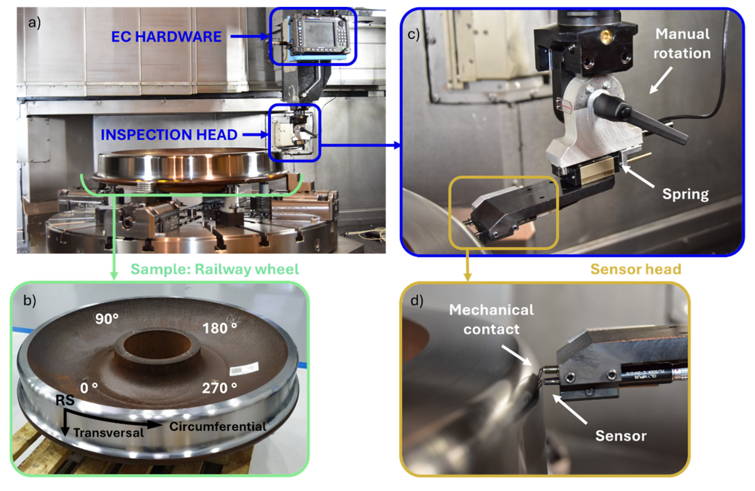
The experimental setup for this study was designed to replicate realistic inspection conditions and consists of a railway wheel mounted on a lathe, along with the associated EC inspection hardware and sensors (see Figure 1a). This configuration allows for controlled evaluation of the EC response under representative operating conditions. The investigated component is a carbon steel railway wheel (Class C according to AAR M-107/M-208 [16]) with a nominal diameter of 969 mm and an average surface roughness of Ra = 0.6 µm (see Figure 1b). Artificial surface defects (notches) were intentionally introduced on the wheel tread under controlled machining conditions. All artificial defects were machined with a constant width of 0.3 mm and a constant depth of 0.25 mm, while three different defect lengths were considered: 1 mm, 6.4 mm, and 8 mm (see Table 1). The notches were oriented both transversely and circumferentially relative to a reference system (RS), defined such that 0° corresponds to the start of the tread region.
The experiments were conducted on a DANOBAT TV 1500 turning lathe (DANOBAT, Elgoibar, Spain) (see Table 2), equipped with a custom-designed inspection head integrated into the machine turret and controlled EC hardware. The inspection head comprises a mechanical support that allows manual adjustment of the sensor orientation, enabling coverage of different analysis zones on the wheel while ensuring that the sensor remains perpendicular to the surface (Figure 1c). In this study, only results related to the tread are presented, although the system can inspect other curved regions of the wheel. The head also incorporates a versatile sensor holder compatible with various sensor types. A mechanical tip maintains contact with the wheel surface, ensuring a constant lift-off distance of 0.1 mm between the sensor and the specimen (see Figure 1d). This distance is regulated by an integrated spring system, which compensates for surface irregularities or minor positional variations. Finally, position signals were recorded directly from the CNC machine with a frequency of 125 Hz while a helical trajectory was applied, featuring a 1 mm axial descent per revolution at lathe chuck rotation speed of 7 rpm.
For EC data acquisition, Omniscan MX hardware (Olympus, Quebec, QC, Canada) was employed, operating at a sampling rate of 1 KHz. This hardware, typically employed in manual inspections, enables comprehensive representation of the measured parameters. In this study, the Impedance Plane representation was used, recording voltage values in both vertical (Vy) and horizontal (Vx) components, which are critical for the classification of component anomalies. A differential EC conventional probe working at 500 kHz was used with the parameters described in Table 1. The excitation frequency (500 kHz) was selected to ensure high sensitivity to shallow defects (0.25 mm), with preliminary tests confirming optimal signal-to-noise ratio and detectability. The active coil diameter of 2 mm, combined with the turret’s 1 mm axial descent per revolution, ensures adequate overlap between inspection trajectories. This 1 mm step also balances inspection speed and spatial resolution, providing sufficient accuracy for the evaluated defects while keeping inspection times practical for industrial use. The extraction of EC signals from the inspection hardware was enabled through the IK-DAS system developed by IDEKO, which allows the acquisition of signals from multiple sensors or selectable voltage channels via dedicated data acquisition software. This setup enables offline visualization of the temporal evolution of the signals and facilitates subsequent analysis.

3. Results and Discussion

3.1. Defect Detection

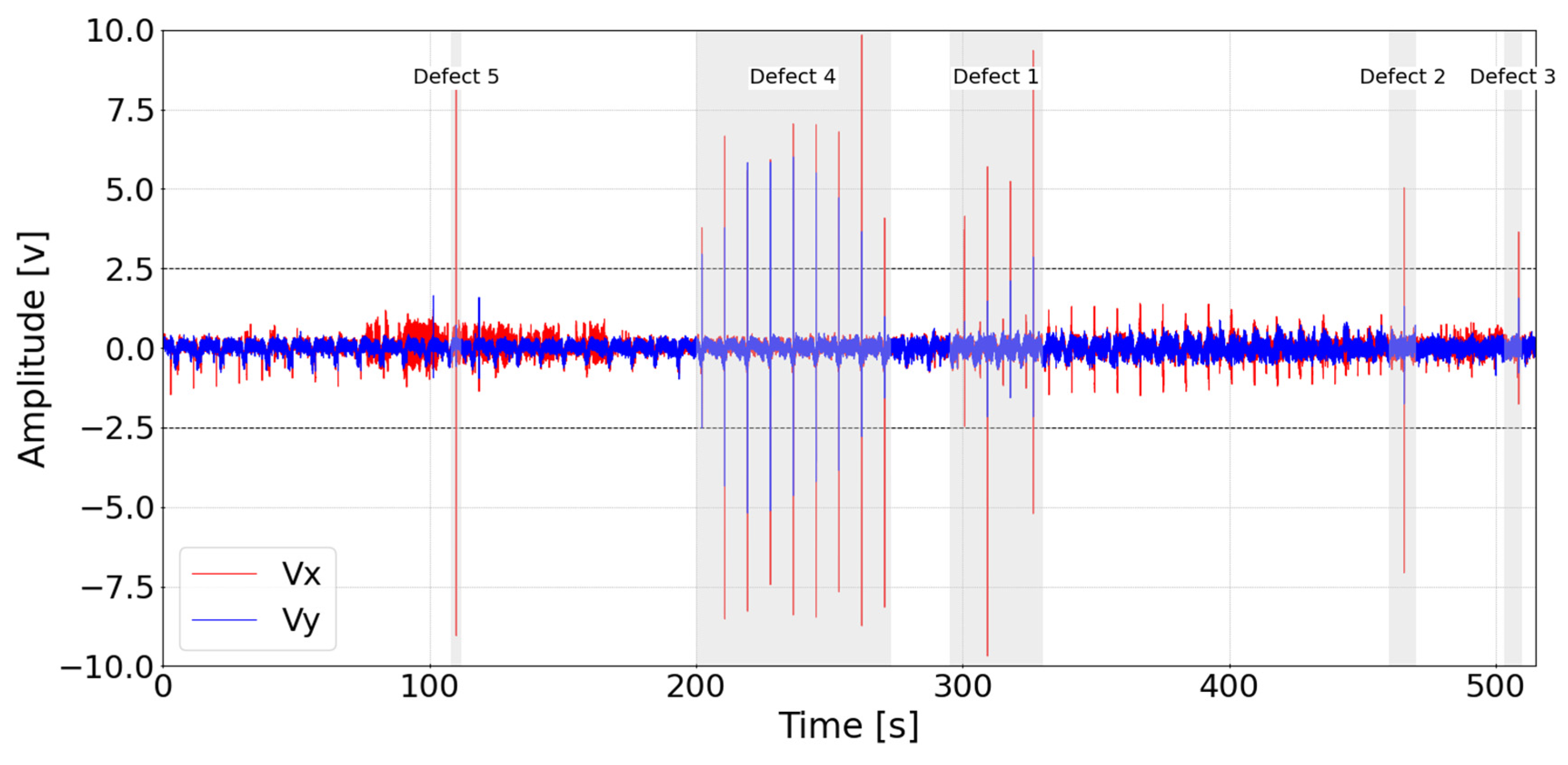
For effective inspection of railway wheels, it is essential that defect-related signals are clearly distinguishable from those of defect-free areas. The temporal evolution of the Eddy Current (EC) signal components, Vx and Vy, is shown in Figure 2. First, it is noticeable that the baseline noise level is very low, suggesting minimal lift-off variation during the inspection. This observation is consistent with the type of inspection head used, which is based on the same concept employed by the authors in previous studies on EC inspections integrated into machine tools, such as grinding [17,18], thereby ensuring measurement consistency. The presence of defects on the wheel tread produces a clear and measurable amplification of the impedance-plane signal components. Among them, the Vx component systematically exhibits higher amplitudes than Vy and is therefore selected as the reference variable for the subsequent analysis. For all inspected defects, the Vx amplitude surpasses the 2.5 V threshold, which can be considered both the reference level and the effective detection limit of the inspection system. The experiments were conducted under conditions that ensured a remarkably low baseline noise level. As a result, the signal-to-noise ratio (SNR) consistently exceeded 36 dB for the five defect types evaluated, confirming the high sensitivity and robustness of the measurement configuration during in-machine inspection. Defect orientation also plays a decisive role in the observed signal amplitudes. Circumferential defects (1, 2, and 3) tend to generate lower Vx amplitudes than transversal defects (4 and 5). This behavior can be attributed to the interaction mechanism between the differential probe and the discontinuity: the coil pair is arranged circumferentially, a configuration that naturally enhances detection capability for transversal defects when the induced eddy-current perturbations are aligned with the probe’s sensitivity axis. Beyond amplitude differences, defect orientation also shapes the temporal morphology of the signals. Transversal defects typically produce multiple amplitude peaks along the inspection path, reflecting the extended interaction length between the probe and the discontinuity (see defect 4 in Figure 2). In contrast, circumferential defects generally generate fewer peaks, as the effective interaction path between the sensor and the defect is significantly shorter (see defect 1 in Figure 2). Despite these differences, both defect types remain clearly distinguishable from background noise independently of the defect length.
The next step consisted of synchronizing the EC signal data with the circumferential coordinate (chuck rotational position) and the transversal coordinate (vertical turret displacement) provided by the CNC system of the lathe. Since the acquisition frequencies of the EC hardware and the CNC system were different (1000 Hz and 125 Hz, respectively), linear signal interpolation was required for positional data (both rotation and translation were at constant velocity) to ensure proper temporal and spatial alignment of the datasets.
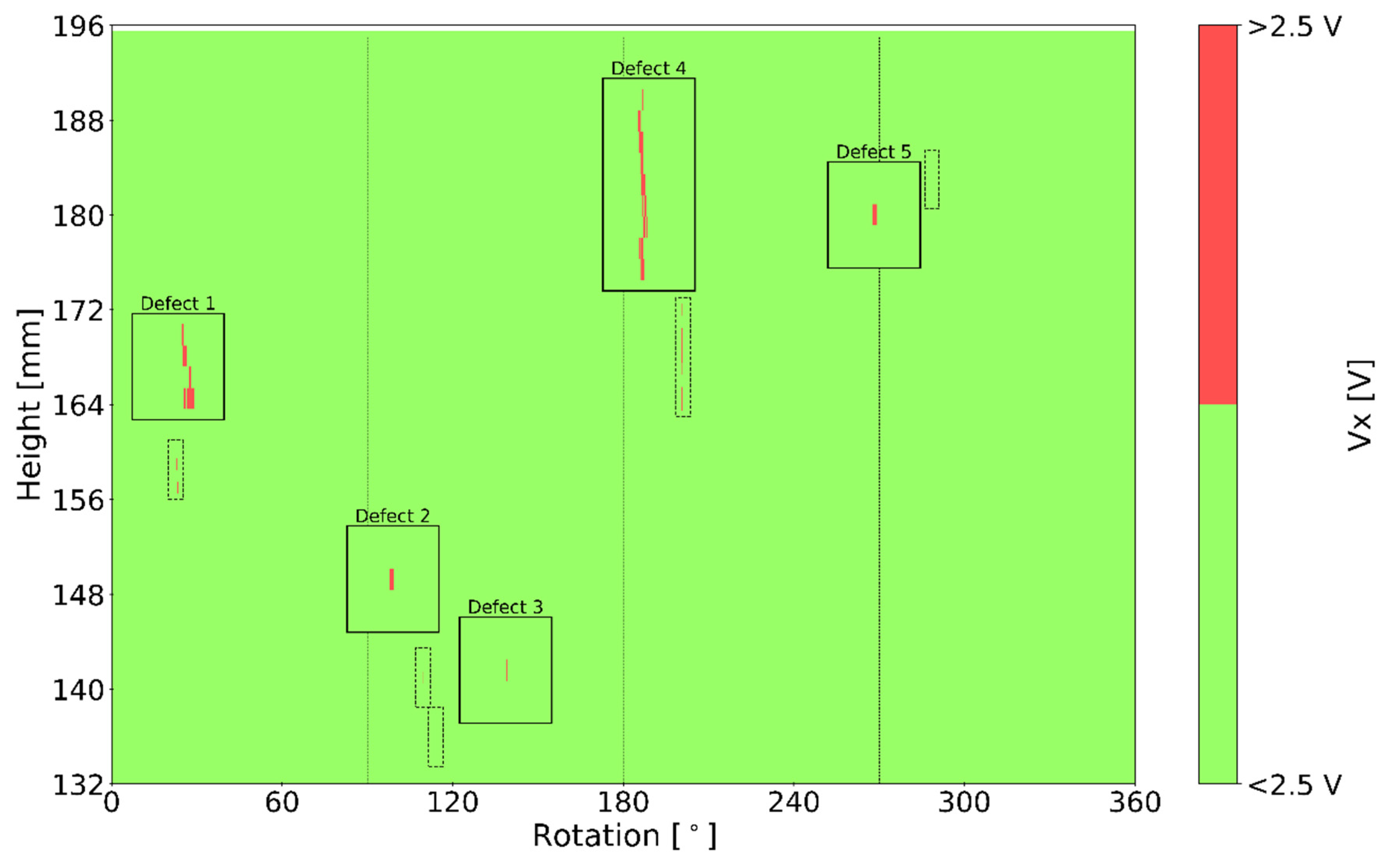
As a result of this synchronization process, a C-scan representation was obtained, see Figure 3. In this map, the y-axis corresponds to the axial (height) position of the component, while the x-axis represents the circumferential angle. To enhance defect visualization, the signal was binarized using a threshold value of 2.5 V; signal amplitudes exceeding this threshold are displayed in red. Given that the flaw dimensions are relatively small compared to the total inspected surface, localized magnification of the C-scan enables clear identification of the defect indications.

3.2. Defect Characterization

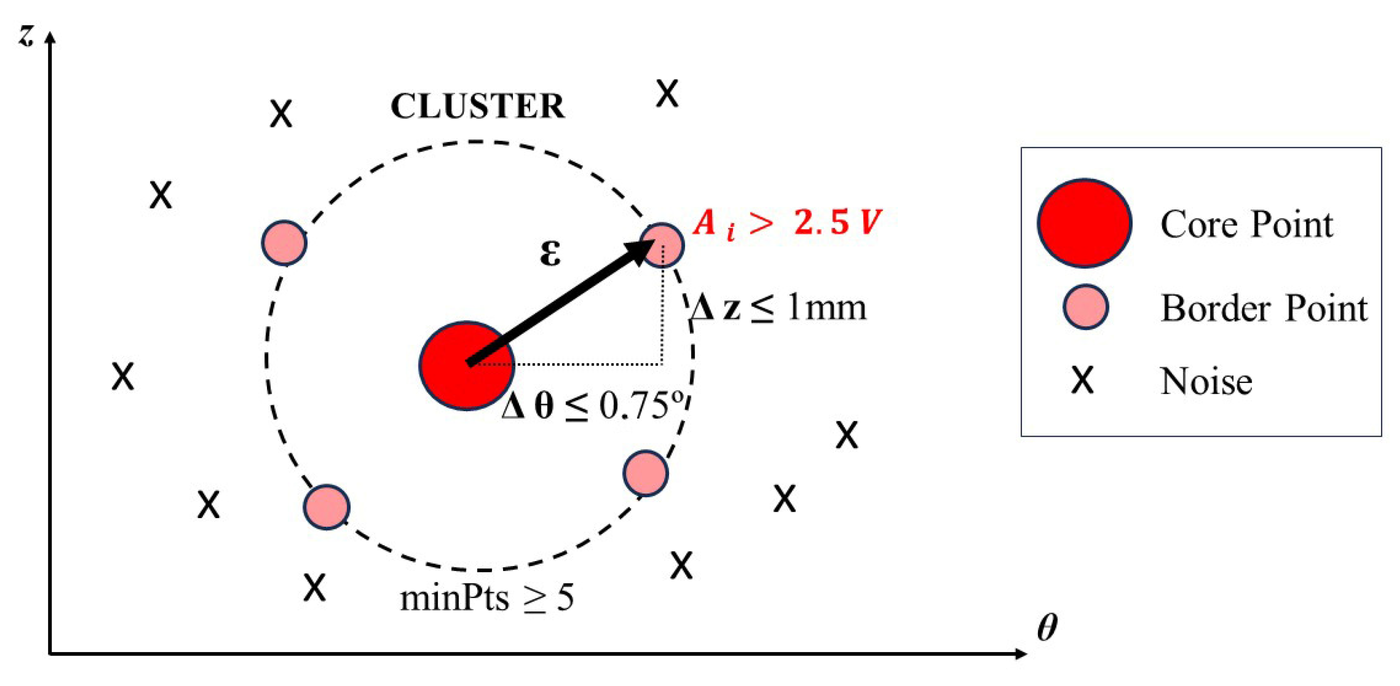
For the localization and sizing of defects, an unsupervised machine learning algorithm based on DBSCAN (Density-Based Spatial Clustering of Applications with Noise) was applied to cluster the Eddy Current (EC) signal data [19]. DBSCAN identifies clusters as regions of high data density separated by regions of low density, without requiring the number of clusters to be specified a priori. Let D R n denote the dataset composed of n-dimensional feature vectors. In this study, each point p i D represents a signal measurement characterized by its amplitude A i , circumferential position θ i , and transversal position z i . The algorithm relies on two main parameters: the neighborhood radius ε , 0.75° for circumferential axis and 1 mm for transversal axis, which defines the maximum distance for two points to be considered neighbours, and m i n P t s , 5 in this case, which specifies the minimum number of neighbouring points required to form a dense region, Figure 4.
While this study employed uniform artificial notches for controlled evaluation, the algorithm is capable of detecting irregular defect geometries, such as real fatigue cracks, by identifying regions of high signal density. Future work will extend validation to field-acquired defects under more complex, real-world conditions.
The ε -neighborhood of a point p     D is given by:
N ε ( p )   =   {   q     D   |   d i s t ( p ,   q )     ε   }
where:
  • N ε ( p ) is the set of neighboring points within radius ε ,
  • d i s t ( p , q ) is the chosen distance metric between points p   and q ,
  • ε is the maximum neighborhood radius.
A point p is classified as a core point if:
| N ε ( p ) |     m i n P t s
where | N ε ( p ) |   denotes the cardinality (number of elements) of the neighborhood, and m i n P t s is the minimum number of neighbors required to define a region of sufficient density. Points that are within the ε-neighborhood of a core point but do not satisfy the density condition themselves are classified as border points, whereas points that are not density-reachable from any core point are labeled as noise.
In the present study, DBSCAN was adapted to cluster EC signal indications corresponding to the same physical discontinuity. Two additional domain-specific constraints were introduced:
  • A point p i was considered eligible for clustering only if its signal amplitude exceeded the detection threshold:
    A i > 2.5   V
    where A i is the signal amplitude of measurement i , and 2.5 V corresponds to the experimentally defined defect detection limit.
  • Two points p i and p j were considered neighbours only if they satisfied both spatial conditions:
    Δ θ = | θ   i θ j |     0.75 ° Δ z = | z i z j |     1   mm
Alternatively, the combined spatial condition can be expressed as a normalized distance criterion:
Δ θ   0.75 ° 2   +   Δ z   1   mm 2     1
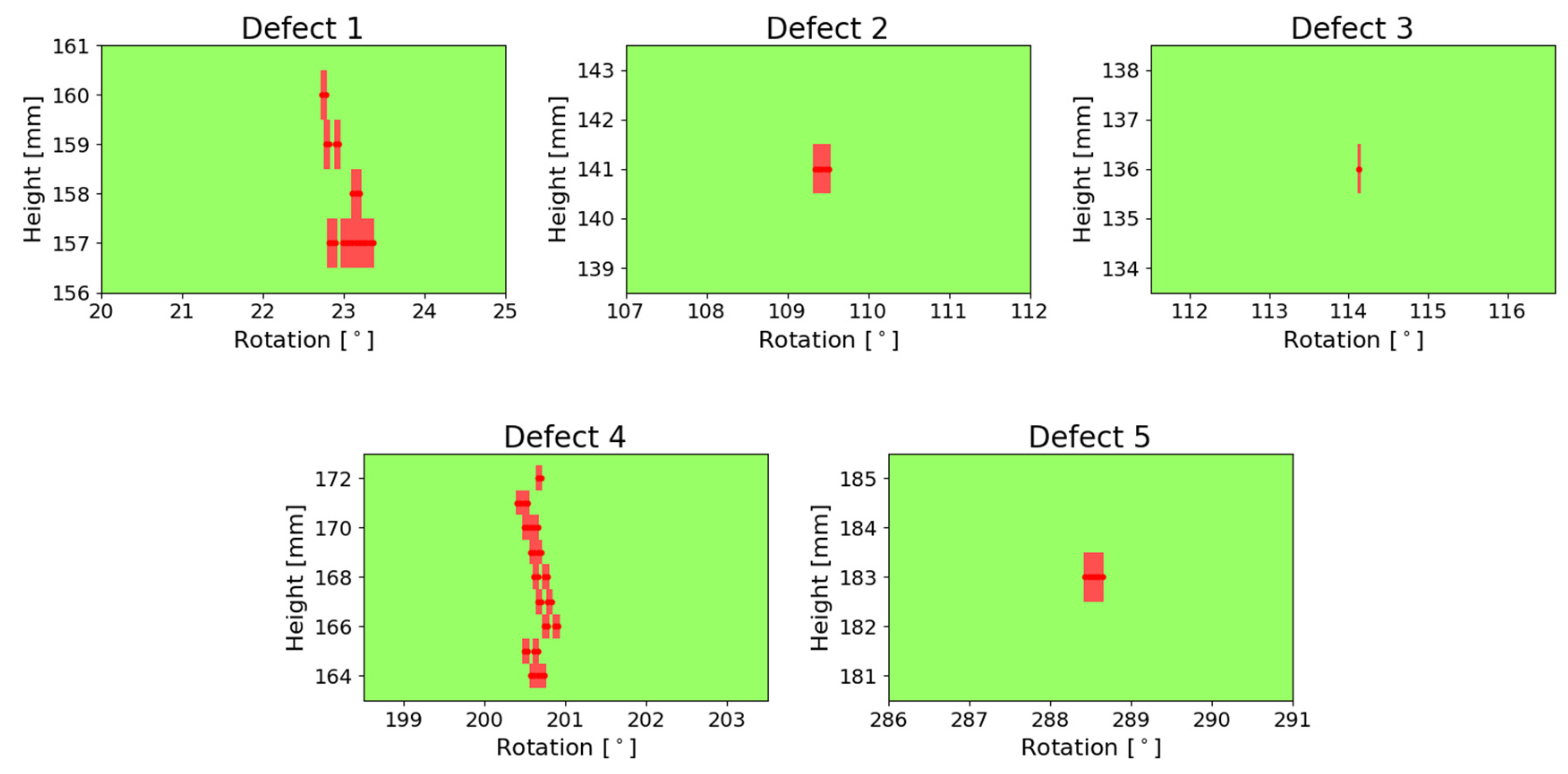
This density-based formulation ensures that clustered signals correspond to spatially coherent defect indications while isolated high-amplitude measurements that do not satisfy the density condition are automatically classified as noise. After applying the DBSCAN-based clustering algorithm, the resulting grouped indications represented in the C-scan are shown in Figure 5 for each individual defect. The proposed clustering framework consistently and unambiguously identified all five defects, regardless of their size, morphology, or orientation, as illustrated by the differences between defects 2 and 4 in Figure 5.
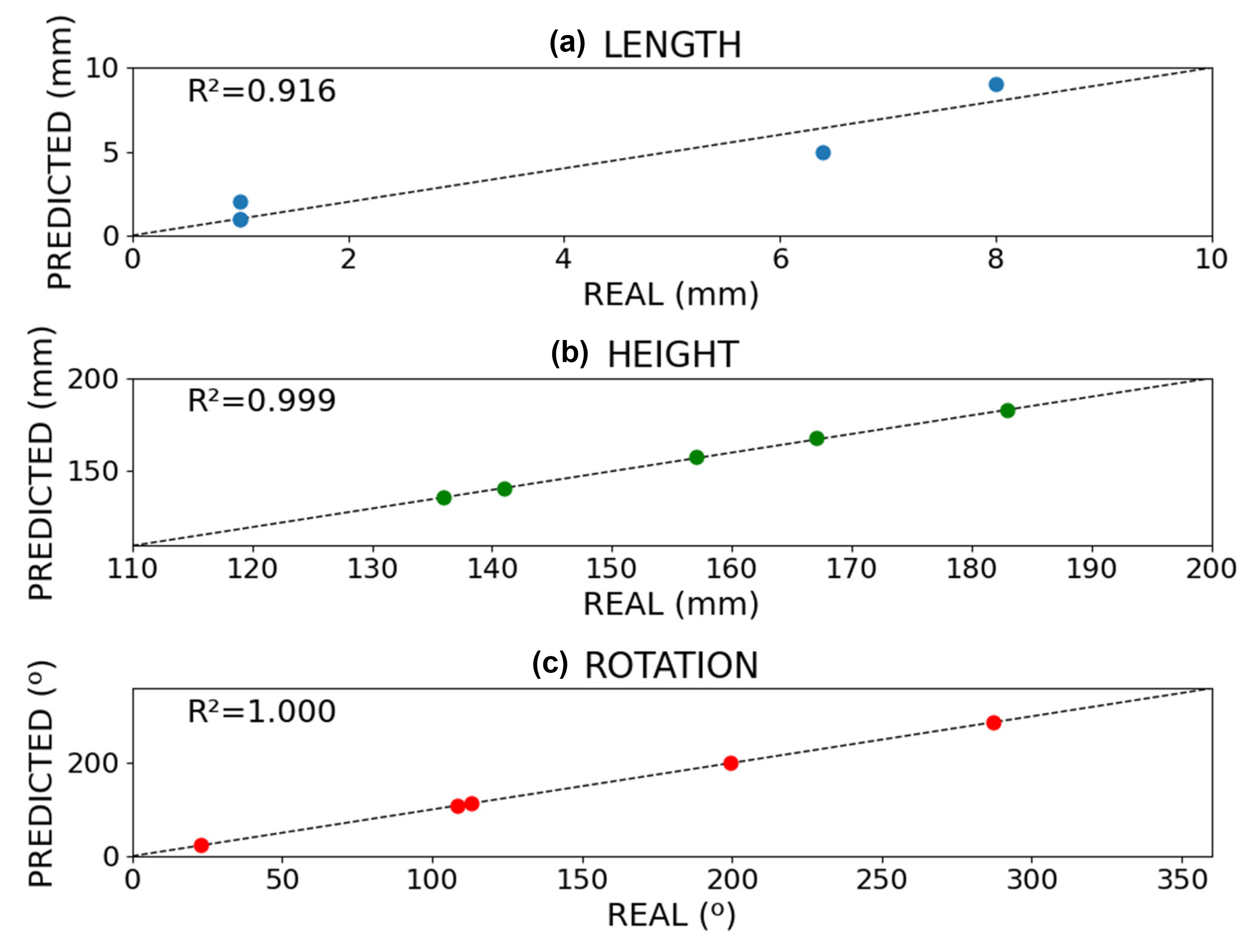
The density-based methodology enables the robust estimation of cluster centroids (geometric barycenters) together with the precise determination of the maximum and minimum spatial extents of each discontinuity in both the axial and circumferential directions. This quantitative characterization provides a direct parametric description of defect geometry derived exclusively from the clustered signal distribution, eliminating the need for manual post-processing or heuristic interpretation. The defect dimensions and positional parameters predicted by the algorithm are summarized in Table 3 and Figure 6, where they are quantitatively compared against the nominal target defect sizes and reference characteristics.
The inspection system supported by the model detects discontinuities with positional accuracy exceeding 99% in both the transversal and circumferential directions. This level of high-fidelity localization allows the extracted parameters to be directly mapped to the applicable acceptance criteria defined by current inspection standards, enabling objective, reproducible, and standards-compliant acceptance or rejection decisions for the evaluated components. Figure 6 shows that the predicted defect lengths exhibit deviations below 8%, which can be attributed to two main sources of error. First, the machined defects exhibit an intrinsic geometric tolerance of approximately 10%, which is on the order of the model accuracy. Second, the vertical displacement of the scanning system is constrained by a machine step of 1 mm, comparable to the measurement uncertainty. Reducing the vertical step increment in the mechanical system would minimize this source of error, thereby bringing the prediction accuracy within acceptable tolerances and enhancing the reliability of the automated defect evaluation process.
The obtained results robustly validate the proposed approach, in which a relatively straightforward inspection system is integrated directly into a turning lathe. This methodology enables the seamless integration of a commercially available system into the production line or with manual hardware typically used by operators during either manufacturing or maintenance inspections. Moreover, by employing a readily deployable DBSCAN-ML algorithm, this methodology establishes a reliable and highly efficient inspection system with minimal adaptation effort, fully compatible with the integration of AI in NDT [20]. The proposed methodology offers notable practical advantages, providing rapid and robust results in scenarios where complex models, such as CNNs [21] or Autoencoder models [22], which are indispensable in specific NDT applications, demand extensive training and significant computational resources. Consequently, their deployment in alternative contexts (particularly in industrial environments with limited integration capacity) can be challenging. In contrast, the proposed approach facilitates efficient and reliable implementation without compromising performance.
Compared to traditional manual inspection techniques such as magnetic particle testing, the present approach offers clear advantages: it eliminates labor-intensive procedures, reduces the risk of operator-induced variability, and allows continuous in-situ monitoring without removing the component from the machine. In addition, compared with dedicated automated systems based on eddy EC [15], this methodology provides additional benefits: it enables ultrafast defect detection and precise localization while the component remains on the machine, achieving high automation performance at a significantly lower cost. Furthermore, it allows rapid deployment across different machines and production lines, enhancing flexibility and scalability in industrial applications.

4. Conclusions

The integration of eddy current (EC) inspection into a CNC turning machine for railway wheels has been demonstrated to be both feasible and industrially applicable. This approach enables real-time, in-machine defect detection, reducing the need for dedicated inspection stations and minimizing operator intervention.
Experimental validation using wheels with artificial defects showed high signal-to-noise ratios (above 36 dB) and reliable identification of defect signatures across different types and orientations. Automated defect characterization with the tailored DBSCAN algorithm accurately localized discontinuities (99% positional accuracy) and estimated defect sizes within industrial tolerances, providing rapid, objective, and repeatable inspection with minimal operator variability.
The system leverages commercially available hardware and lightweight algorithms, enabling straightforward deployment in existing production and maintenance lines. Its design allows easy adaptation to different inspection requirements, and material-specific calibration ensures consistent sensitivity across various types of railway steel.
Future work will focus on extending the methodology to subsurface defect detection using lower or multi-frequency excitation strategies and optimized probe configurations, as well as validating the system under real industrial conditions with a wider range of defect types.
Overall, this study presents a practical, scalable, and cost-effective solution for digitalized in-machine railway wheel inspection, paving the way for safer, more efficient, and higher-quality wheel maintenance and manufacturing processes.

Author Contributions

Conceptualization, J.L.L. and J.M. (Jokin Munoa); Software, P.R.; Validation, J.M. (Julen Mendikute), I.S. and I.A.-M.; Investigation, J.L.L., J.M. (Julen Mendikute), I.S., P.R. and I.A.-M.; Resources, J.M. (Jokin Munoa); Writing—original draft, J.L.L.; Writing—review & editing, I.S. and J.M. (Jokin Munoa); Project administration, I.S.; Funding acquisition, J.M. (Jokin Munoa). All authors have read and agreed to the published version of the manuscript.

Funding

This work has been partially done under the framework of the HANDIA Project (ELKARTEK programme, reference KK-2025/00068).

Data Availability Statement

The original contributions presented in this study are included in the article. Further inquiries can be directed to the corresponding author.

Acknowledgments

The authors also gratefully acknowledge Jon Ander Ealo from CFAA (Centro de Fabricación Avanzada Aeronáutica) for his assistance in carrying out the experimental trials associated with the project and for their valuable technical support.

Conflicts of Interest

The authors declare no conflict of interest.

References

  1. Rudlin, J.; Raude, A.; Völz, U.; Conte, A.L. New Methods of Rail Axle Inspection and Assessment. In Proceedings of the 18th World Conference on Nondestructive Testing, Durban, South Africa, 16–20 April 2012. [Google Scholar]
  2. Railway Inspectorate. Railway Accident at Rickerscote; HM Railway Inspectorate: London, UK, 1996. [Google Scholar]
  3. Manca, D.; Brambilla, S.; Totaro, R. A Quantitative Assessment of the Viareggio Railway Accident. In Computer Aided Chemical Engineering; Elsevier: Amsterdam, The Netherlands, 2010; Volume 28, pp. 187–192. [Google Scholar] [CrossRef]
  4. Ma, T.; Sun, Z.; Chen, Q. Study on crack features in images of fluorescent magnetic particle inspection for railway wheelsets. Insight 2018, 60, 519–524. [Google Scholar] [CrossRef]
  5. Montinaro, N.; Epasto, G.; Cerniglia, D.; Guglielmino, E. Laser ultrasonics inspection for defect evaluation on train wheel. NDT E Int. 2019, 107, 102145. [Google Scholar] [CrossRef]
  6. Cavuto, A.; Martarelli, M.; Pandarese, G.; Revel, G.M.; Tomasini, E.P. Train wheel diagnostics by laser ultrasonics. Measurement 2016, 80, 99–107. [Google Scholar] [CrossRef]
  7. Cavuto, A.; Martarelli, M.; Pandarese, G.; Revel, G.M.; Tomasini, E.P. Experimental investigation by laser ultrasonics for high speed train axle diagnostics. Ultrasonics 2015, 55, 48–57. [Google Scholar] [CrossRef] [PubMed]
  8. Rolek, P.; Bruni, S.; Carboni, M. Condition monitoring of railway axles based on low frequency vibrations. Int. J. Fatigue 2016, 86, 88–97. [Google Scholar] [CrossRef]
  9. Kim, J. Non-Destructive Characterization of Railway Materials and Components with Infrared Thermography Technique. Materials 2019, 12, 4077. [Google Scholar] [CrossRef] [PubMed]
  10. Wei, X.; Chen, Y.; Lu, C.; Chen, G.; Huang, L.; Li, Q. Acoustic emission source localization method for high-speed train bogie. Multimed. Tools Appl. 2020, 79, 14933–14949. [Google Scholar] [CrossRef]
  11. Janousek, L.; Capova, K.; Yusa, N.; Miya, K. Multiprobe Inspection for Enhancing Sizing Ability in Eddy Current Nondestructive Testing. IEEE Trans. Magn. 2008, 44, 1618–1621. [Google Scholar] [CrossRef]
  12. Hashizume, H.; Yamada, Y.; Miya, K.; Toda, S.; Morimoto, K.; Araki, Y.; Satake, K.; Shimizu, N. Numerical and experimental analysis of eddy current testing for a tube with cracks. IEEE Trans. Magn. 1992, 28, 1469–1472. [Google Scholar] [CrossRef]
  13. Lanzagorta, J.; Aizpurua, I.; Vázquez, P.R.; Castro, I. New ways to inspect railway axles: From simulation to experimental validation. NDT E Int. 2021, 121, 102439. [Google Scholar] [CrossRef]
  14. Lanzagorta, J.L.; Decitre, J.M.; Nozais, F.; Aizpurua, I.; Hidalgo-Gato, R.; Castro, I.; Lasa, L. New inspection approaches for railway based on Eddy Current. In Proceedings of the 12th European Conference on Non-Destructive Testing, Münster, Germany, 11–15 June 2018. [Google Scholar]
  15. Rockstroh, B.; Kappes, W.; Walte, F.; Kroning, M.; Bessert, S.; Schafer, W.; Schallert, R.; Bahr, W.; Joneit, D.; Montacher, A.; et al. Ultrasonic and eddy current inspection of rail wheels and wheel set axles. In Proceedings of the 17th World Conference on Nondestructive Testing, Shanghai, China, 25–28 October 2008. [Google Scholar]
  16. AAR M-107/M-208; Wheels, Carbon Steel. Association of American Railroads: Washington, DC, USA, 2020.
  17. Vázquez, P.R.; Lanzagorta, J.; Mendikute, J.; Barrenetxea, D.; Sergeeva-Chollet, N.; Godino, L. Surface Integrity Evolution in Grinding by Means of In-Process Eddy Current Inspections. Procedia CIRP 2024, 123, 392–397. [Google Scholar] [CrossRef]
  18. Lanzagorta, J.; Urgoiti, L.; Vazquez, P.R.; Barrenetxea, D.; Sánchez, J.A. Experimental approach for a grinding burn in-process inspection system based on Eddy Current. Procedia CIRP 2020, 87, 391–396. [Google Scholar] [CrossRef]
  19. Ester, M.; Kriegel, H.-P.; Xu, X. A Density-Based Algorithm for Discovering Clusters in Large Spatial Databases with Noise; AAAI Press: Washington, DC, USA, 1996. [Google Scholar]
  20. EPérez, E.; Ardıç, C.E.; Çakıroğlu, O.; Jacob, K.; Kodera, S.; Pompa, L.; Rachid, M.; Wang, H.; Zhou, Y.; Zimmer, C.; et al. Integrating AI in NDE: Techniques, trends, and further directions. NDT E Int. 2025, 156, 103442. [Google Scholar] [CrossRef]
  21. Mendikute, J.; Carmona, I.; Aizpurua, I.; Bediaga, I.; Castro, I.; Galdos, L.; Lanzagorta, J.L. Defect detection in wind turbine blades applying Convolutional Neural Networks to Ultrasonic Testing. NDT E Int. 2025, 154, 103359. [Google Scholar] [CrossRef]
  22. Thon, A.; Painchaud-April, G.; Le Duff, A.; Bélanger, P. U-NET autoencoder for amplitude recovery on binarized Full Matrix Captures. NDT E Int. 2025, 156, 103481. [Google Scholar] [CrossRef]
Figure 1. (a) Set up of the overall inspection system with detailed views of: (b) the wheel to be inspected, (c) the automatic Eddy Current (EC) inspection set-up on the lathe and (d) inspection probe head.
Metals 16 00449 g001
Figure 2. Vx and Vy evolution as a function of time.
Metals 16 00449 g002
Figure 3. EC C-scan of the wheel tread, with defect regions magnified to enhance clarity and facilitate detailed inspection.
Metals 16 00449 g003
Figure 4. Algorithm framework for automatic defect detection and characterization.
Metals 16 00449 g004
Figure 5. Clusters generated by the application of the model. The red dots represent each individual element of the cluster associated with the EC signal.
Metals 16 00449 g005
Figure 6. Parity plots: (a) Lenght position, (b) Height position, (c) Rotation position.
Metals 16 00449 g006
Table 1. Component details and defects.
Railway Wheel
MaterialDiameter (mm)Roughness-Ra (µm)
Carbon Steel Class C9690.6
Artificial Notches
Defect numberOrientationDimensions [mm]Location [mm]/[°]
LengthWidthDepthHeightRotation
1Circumferential6.40.30.2515723.03
21141108.53
31136113.02
4Transversal8167199.59
51183286.98
Table 2. In-machine inspection system.
Machine
Turning lathe Danobat TV-1500
Speed (rpm)Acquisition frequency (Hz)
7125
EC Configuration
EC-HardwareEC-Probe
Olympus MX
(1 KHz acquisition frequency)
Probe TypeActive diameter (mm)
Differential2
Inspection parameters
Voltage (V)Frequency (kHz)Lift-off (mm)Gain (dB)
15000.185
Table 3. Comparison Between Model-Predicted Parameters and Reference Defect Measurements.
Defect NumberOrientationDimensions [mm]Location
LengthHeight (mm)Rotation (°)
RealPredictedRealPredictedRealPredicted
1 Circumferential6.45157157.7723.0323.03
211141141108.53109.42
312136136113.02114.13
4Transversal89167167.72199.59200.64
511183183286.98288.54
Disclaimer/Publisher’s Note: The statements, opinions and data contained in all publications are solely those of the individual author(s) and contributor(s) and not of MDPI and/or the editor(s). MDPI and/or the editor(s) disclaim responsibility for any injury to people or property resulting from any ideas, methods, instructions or products referred to in the content.