Abstract
Test specimens fabricated from 42CrMo4 steel were subjected to heat treatment comprising quenching followed by high-temperature tempering. This treatment is commonly referred to as hardening, and the result is a tempered sorbite microstructure that provides a balanced combination of strength and plasticity. In order to improve the hardness and wear resistance of the contact surfaces, two types of physical vapor deposition (PVD) coatings were deposited onto the specimens: the first was a two-component architecture Cr/CrTiAl and the second was a multilayer Cr/(CrTiAl)N/CrTiAl. In both configurations, an intermediate chromium adhesion layer was initially deposited to enhance interfacial bonding with the substrate. The adhesion strength of the deposited coatings to the steel substrates was evaluated using a standardized adhesion test. The adhesion quality was classified as HF1 (the highest adhesion class in the HF1–HF6 scale, defined in EN ISO 26443), indicating excellent interfacial bonding. The hardness and modulus of elasticity of both coatings were determined through nanoindentation. According to the measured hardness values of the two coatings, 27.3 GPa (Cr/CrTiAl) and 37.5 GPa (Cr/(CrTiAl)N/CrTiAl), they can be classified as hard coatings (hardness greater than 20 GPa). Despite the difference in hardness, the two coatings have comparable elastic modulus values: Eit = 353 GPa for the two-component architecture coating and Eit = 349 GPa for the three-component architecture coating. Tribological characterization was performed using the ball-on-disc method under dry sliding conditions over a total sliding distance of 59 m, whereby the friction coefficient (µ) was recorded. Additionally, the wear rate of the applied coatings was calculated from the measured wear volumes or profiles. The two coatings have comparable friction coefficient values (Cr/CrTiAl–μ = 0.362, Cr/(CrTiAl)N/CrTiAl–μ = 0.325), but the three-component architecture coating Cr/(CrTiAl)N/CrTiAl has a lower wear rate (k = 1.64 × 10⁻⁴) compared to the two-component architecture coating Cr/CrTiAl, which has a wear rate of k = 7.6 × 10⁻⁴. The investigated coatings have hardness, modulus of elasticity and friction coefficient values competitive with those of nitride coatings (two-component architecture and three-component architecture), and their wear rate also corresponds to generally accepted values.
1. Introduction
One of the criteria for classifying steels is the content of alloying elements, excluding carbon. Steels are categorized as low-alloyed when the alloying elements amount to up to approximately 2.5 wt%, medium-alloyed when ranging from 2.5 to 10 wt%, and high-alloyed when exceeding 10 wt%. Alloyed steels are further subdivided into structural and tool steels. Low-alloyed structural steels are extensively utilized in industrial applications due to their favorable combination of mechanical properties. Steel 42CrMo4, equivalent to AISI 4140, represents a typical low-alloyed medium-carbon structural steel. This steel is characterized by high strength, good ductility, hardenability, and resistance to temper embrittlement. It can be subjected to various heat treatment regimes, including annealing with phase recrystallization (full annealing or normalizing) or quenching followed by tempering. The tempering temperature following quenching determines the final mechanical properties of the material. Low-temperature tempering is conducted in the range of 150–250 °C, yielding a microstructure of tempered martensite, which exhibits high hardness and wear resistance, but limited tolerance to dynamic loads due to retained brittleness. Medium-temperature tempering, performed at 350–500 °C, produces tempered troostite, imparting enhanced plasticity and impact toughness. High-temperature tempering is carried out at 500–650 °C to achieve a microstructure of tempered sorbite, which provides an optimal balance of increased plasticity, impact toughness, and yield strength, accompanied by a moderate reduction in hardness and tensile strength.
Extensive data on the effects of heat treatment regimens on the microstructure and properties of 42CrMo4 steel are available in the literature [1,2,3,4,5,6,7,8,9,10]. High-temperature tempering yields the most balanced combination of strength and ductility; however, in certain cases, when parts are simultaneously subjected to dynamic loads and wear, the reduced surface hardness associated with this treatment can represent a limitation. To address this drawback, surface hardening treatments such as nitriding, ion nitriding, or ferritic nitrocarburizing are applied to QT-treated 42CrMo4 components. These thermochemical processes introduce nitrogen into the surface layer at temperatures of 500–580 °C, which remain below the tempering range that would adversely affect the core QT microstructure. Relevant studies documenting improvements in hardness, wear resistance, and corrosion resistance through these processes are reported in the literature [11,12,13,14,15,16,17,18,19,20,21,22]. Nevertheless, such diffusion-based enrichment processes with nitrogen and carbon are also characterized by some disadvantages, such as prolonged processing times and the formation of structures with less hard phases. This necessitates the use of other technological processes to increase the hardness and wear resistance of the contact surfaces of parts made of 42CrMo4 QT steel.
Hard coatings deposited in a vacuum environment using PVD methods is a modern ecological friendly alternative to chemical and electrochemical coatings, which have a negative impact on the environment [23]. These coatings aim to enhance service life by combining high hardness, wear resistance, and other functional properties [24]. Among PVD techniques, magnetron sputtering is widely adopted, owing to its versatility, system compactness, and compatibility with diverse substrate materials [25]. Conventional direct current magnetron sputtering (DCMS) suffers from relatively low plasma ionization degrees; however, this limitation is mitigated by unbalanced magnetron sputtering in a closed-field configuration, which promotes uniform plasma distribution, elevated particle energy, and the deposition of denser, more adherent hard coatings [26]. Through unbalanced magnetron sputtering, it is possible to deposit hard nitride coatings. A typical representative of this group of coatings is the compound chromium nitride (CrN), which has a face-centered cubic crystal lattice and a space group Fm3m [27]. A characteristic of this compound is that it is stable in two forms: cubic CrN and hexagonal Cr2N. The formation of these two modifications depends on the coating deposition parameters and is particularly influenced by reactive nitrogen gas flow (N2) [28]. The advantages of CrN coating include a low friction coefficient, low internal stress, high chemical resistance, wear resistance and thermal stability [29]. Titanium nitride (TiN) is another prevalent binary nitride coating used due to its high chemical stability, high mechanical hardness and high-temperature and corrosion resistance [30]. The TiN coating crystallizes in the cubic Fm-3m space group. When titanium reacts with nitrogen, two types of compounds, ε-Ti2N and δ-TiN, can be formed [30], which depends entirely on the amount of nitrogen. Alloying TiN with aluminum to form TiAlN enhances oxidation resistance, hardness, and corrosion performance. Similarly, the incorporation of Al into CrN yields CrAlN coatings with superior abrasive wear, oxidation, and tribological characteristics [31]. Tribological evaluation of binary and ternary nitride coatings deposited on various substrates is critical for assessing their mechanical integrity, including strength and resistance to brittle failure [32]. A disadvantage of binary compounds is their high friction coefficient and deterioration of their oxidation resistance at operating temperatures exceeding 800 °C. In mechanical, automotive, and related industries, vacuum-deposited hard nitride coatings represent an ecologically sustainable substitute for chemical and electrochemical alternatives, enabling optimized component performance through multicomponent coating architectures.
Therefore, the aim of this study was to evaluate the adhesion strength of two-component Cr/CrTiAl and three-component architecture Cr/(CrTiAl)N/CrTiAl PVD coatings deposited onto quenched and tempered 42CrMo4 steel substrates, along with characterization of their mechanical properties (hardness and elastic modulus), friction coefficients, and wear rates.
2. Materials and Methods
2.1. Investigated Material
To conduct the present experiments, test specimens with dimensions of diameter d = 32 mm and thickness 5 mm were made of 42CrMo4 QT steel (1.7225, EN 10083-3:2006; BDS EN ISO 683-2:2018, European Standard, Bulgarian Institute for Standardization, Sofia, Bulgaria, 14 November 2018) [33], with the chemical composition shown in Table 1. The chemical composition of the steel was determined using an Oxford Instruments FOUNDRY-MASTER UV apparatus, Abingdon/High Wycombe, Oxfordshire, UK [34].

Table 1.
Chemical composition of steel 42CrMo4 QT [wt %].
The test specimens were subjected to heat treatment quenching and high-temperature tempering using a Hobersal GB7-132 PAD P thermal furnace (Hobersal, Barcelona, Spain). The quenching process involved austenitization at 880 °C for 15 min to ensure homogenization of the austenitic phase, followed by immersion quenching in oil. High-temperature tempering was subsequently performed at 600 °C with a holding time of 2 h, after which the specimens were cooled to room temperature in still air. The resulting hardness of the heat-treated specimens was measured in the range of 28–30 HRC, in accordance with BDS EN ISO 6508-1:2024 (Metallic materials—Rockwell hardness test—Part 1: Test method; identical to ISO 6508-1:2023, European Standard, Bulgarian Institute for Standardization, Sofia, Bulgaria, 19 February 2014) [35].
2.2. Coating Deposition Process
To enhance the surface hardness and wear resistance of the contact surfaces, PVD coatings were deposited via unbalanced magnetron sputtering using an MS 700 system of ΙNORCOAT (Ostfildern, Germany). It has a cylindrical chamber with six magnetrones equally distributed in a closed-field circular array, surrounding a central rotating substrate holder. Two coating architectures with Cr sublayers were selected for deposition and subsequent characterization: a multilayer coating composed of Cr/CrTiAl and a multilayer coating composed of Cr/(CrTiAl)N/CrTiAl (Figure 1). The inclusion of both configurations enabled comparative evaluation of the influence exerted by the nitride interlayers on overall coating performance, as the mechanical properties of the hard nitride layers and the intermediate metallic layers collectively determine coating integrity, adhesion, and tribological behavior.
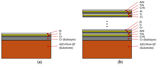
Figure 1.
Coating architecture, (a) Cr/CrTiAl structure, (b) Cr/(CrTiAl)N/CrTiAl structure.
Prior to coating deposition, the specimen surfaces were prepared by grinding and polishing on a Metcon Forcimat machine (Bursa, Turkey) [36,37], followed by ultrasonic cleaning. Deposition was conducted in an MS 700 magnetron sputtering system (Inorcoat, Ostfildern, Germany) equipped with six magnetrons. High-purity targets were employed, including chromium (Cr, 99.8%), aluminum (Al, 99.99%), and titanium (Ti, 99.8%). In order to improve adhesion and coating density, preliminary ion etching was performed in argon plasma with a high substrate bias voltage, while a moderate bias was maintained during deposition. The processes took place in argon plasma, with the supply of reactive nitrogen gas to form the nitride layers. For the three-component architecture coating, Cr/(CrTiAl)N/CrTiAl, the deposition sequence consisted of six layers. Initial ion cleaning was carried out in argon plasma with a substrate bias of 600 V for 480 s. An adhesion-promoting chromium interlayer was then deposited for 800 s. The three-component architecture stack was built as follows: (i) first the (CrTiAl)N layers, (ii) second the CrTiAl layers, (iii) third the (CrTiAl)N layer, (iv) fourth the CrTiAl layer, and (v) fifth the (CrTiAl)N layer. The deposition times of the individual layers of the three-component architecture were as follows: (i) first (CrTiAl)N layers—2700 s, (ii) second CrTiAl layers—600 s, (iii) third (CrTiAl)N layer—2700 s, (iv) fourth CrTiAl layer—600 s, and (v) fifth (CrTiAl)N layer—3600 s. Deposition utilized two Cr targets at 1.6 kW each, one Al target at 0.1 kW, and one Ti target at 0.1 kW. The argon working gas flow was set to 120 sccm, and the reactive nitrogen flow was set to 23 sccm, maintaining a chamber pressure of 2.5 × 10⁻³ mbar.
For the multilayer Cr/CrTiAl coating, ion cleaning was performed at a substrate bias of 340 V for 3600 s, followed by deposition of a Cr adhesion layer for 800 s. The CrTiAl layer was subsequently deposited using Cr targets at 0.6 kW, Ti at 0.9 kW, and Al at 0.9 kW. The deposition time was 7 200 s, with an argon flow of 130 sccm and a chamber pressure of 2.5 × 10⁻³ mbar without using reactive nitrogen gas. In both processes, the substrate temperature was maintained at 230 °C, and the target-to-substrate distance was 60 mm.
2.3. Mechanical Testing, Nano-Indentation and Evaluation, and Tribological Testing
Adhesion of the coatings to the substrate was evaluated using the Rockwell indentation method, in accordance with EN ISO 26443, European Standard, Bulgarian Institute for Standardization, Sofia, Bulgaria, 19 February 2014 [38]. A standard Rockwell C indenter (120° diamond cone, nominal tip radius 200 µm) was applied under a load of 981 N using a VEB WPM Leipzig hardness tester (Leipzig, Germany). The resulting indentation craters were examined optically with a Best Scope BS-6022TRF microscope (Beijing Bestscope Technology Co., Ltd., Beijing, China) and Capture 2.1 software. Coating damage was classified into adhesion quality grades of HF1 to HF6, based on the extent of radial cracking and circumferential delamination around the indent, where HF1–HF2 indicate excellent to good adhesion (minimal cracking) and higher grades reflect progressive interfacial failure.
Coating thickness was determined by the ball-cratering (Calotest) method, according to ISO 26423:2009, ISO 2009, Published in Switzerland [39], using a Calotest CAT2 instrument (Anton Paar, Austria). A 20 mm diameter steel ball was rotated against the coated surface at 1200 rpm while a 0.5 µm diamond suspension was applied as an abrasive. Cratering durations ranged from 10 to 20 s. The resulting spherical craters were imaged optically, and thickness was calculated from geometrical measurements of the crater dimensions.
The hardness and elastic modulus of the coatings were measured by nanoindentation on an Anton Paar instrument (Graz, Austria) equipped with a Berkovich diamond indenter. A maximum load of 20 mN was applied, and the Oliver–Pharr method was employed for data analysis and property calculation [40,41].
Tribological characterization was performed on a tribotester (Jinan Hengxu Test Technology Co., Ltd., Jinan, China) under dry sliding conditions at room temperature. The ball-on-disc configuration was adopted, utilizing three 100Cr6 steel spheres (diameter 6.37 mm, hardness 830 HV0.1) positioned at 120° intervals on a circle with a 25 mm diameter relative to the rotation axis (as illustrated in Figure 2). A normal load of 10 N was applied, with a rotational speed of 100 rpm over a test duration of 5 min, corresponding to a total sliding distance of 59 m. The friction coefficient (µ) was continuously recorded during testing.
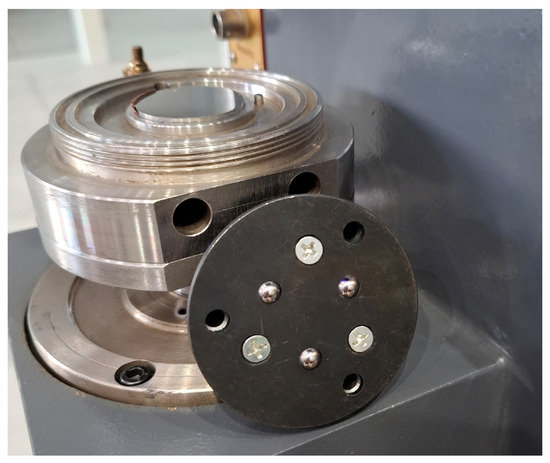
Figure 2.
Type of setup used to determine the friction coefficient (µ).
Prior to the tribological tests, the surface roughness of the coated test specimens was quantified using a portable contact profilometer roughness tester, model INSIZE ISR-C002 (Insize, Suzhou City, China). This instrument, capable of measuring multiple roughness parameters (including Ra, Rz, Rq, and others), with a resolution of 0.001 µm and a measuring range up to approximately 160 µm, was employed to assess the as-deposited coating topography.
The profilometer was calibrated against a reference roughness standard with a nominal Ra value of 1.2 µm prior to the commencement of measurements. For each individual measurement, the instrument’s position was carefully aligned and adjusted relative to the specimen surface to ensure accurate stylus contact and reliable data acquisition [42,43]. Multiple traces were recorded on representative areas of the coated surfaces.
Following the completion of the tribological tests, the same profilometer was utilized to characterize the wear tracks formed on the coated specimens. Cross-sectional profiles across the wear scars were acquired, enabling quantitative determination of the worn volume.
3. Results
Adhesion of the deposited coatings was assessed in accordance with EN ISO 26443, (European Standard, Bulgarian Institute for Standardization, Sofia, Bulgaria, 19 February 2014) [38], which specifies a qualitative Rockwell indentation method for evaluating the adhesion of thin coatings After heat treatment, the 42CrMo4 QT steel had hardness values of 28–30 HRC; therefore, the adhesion class was determined according to the Rockwell method using a 120° diamond cone indenter with a 200 µm tip radius and a 981 N load. This load selection ensured that substrate plastic deformation remained moderate while still generating sufficient stress at the coating–substrate interface to reveal adhesion characteristics without overwhelming the coating response. Optical examination of the indentation craters revealed no evidence of coating delamination or spallation in either coating system. Consequently, the adhesion quality was classified as HF1 (the highest adhesion class in the HF1–HF6 scale defined in EN ISO 26443, European Standard, Bulgarian Institute for Standardization, Sofia, Bulgaria, 19 February 2014), indicating excellent interfacial bonding. Distinct differences in crack morphology were observed between the two architectures. For the two-component architecture Cr/CrTiAl coating, radial cracks propagated in a predominantly spiral pattern extending from the crater edge inward, without significant branching or secondary cracking. This behavior is attributed to the homogeneous nature of the single metallic/ternary interlayer structure, which allows stress relaxation primarily through continuous crack extension rather than three-component architecture deflection. In contrast, the three-component architecture Cr/(CrTiAl)N/CrTiAl coating exhibited multiple radial cracks localized within the contact zone near the crater periphery, consistent with stress concentration and deflection at the interfaces between the nitride and metallic sublayers. However, no cracks of critical length or morphology leading to delamination were detected (Figure 3), confirming the absence of interfacial weakness and the beneficial role of the three-component architecture design in distributing deformation energy.
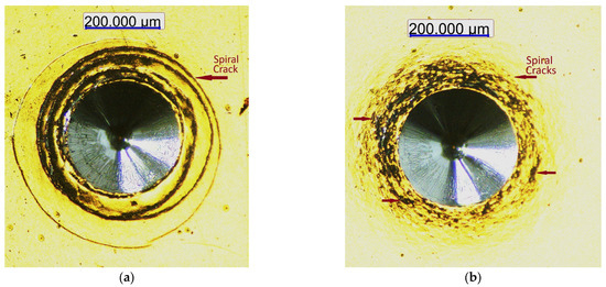
Figure 3.
Evaluation of coating adhesion: (a) two-component architecture coating Cr/CrTiAl, (b) three-component architecture coating Cr/(CrTiAl)N/CrTiAl.
The results of the studies conducted to determine the total thickness of the applied coatings show that, with the used parameters of the coating processes, the two-component architecture coating Cr/CrTiAl has a thickness of 2.3 µm and the three-component architecture coating Cr/(CrTiAl)N/CrTiAl has a thickness of 3.8 µm. Figure 4a shows the recorded total thickness of the two-component architecture coating Cr/CrTiAl, and no imprint was recorded during the test to be used to calculate the thickness of the adhesion-promoting chromium interlayer. The total thickness of the coating was determined during the study of the three-component architecture coating Cr/(CrTiAl)N/CrTiAl. Data were also obtained for the thickness of the outermost (CrTiAl)N layer ≈ 1.4 µm (Figure 4b), but no craters were obtained to calculate the thicknesses of the adhesion-promoting chromium interlayer and the individual layers constituting the three-component architecture of the coating. Based on the measured thickness of the outermost (CrTiAl)N layer (≈1.4 µm) of the three-component architecture coating Cr/(CrTiAl)N/CrTiAl and the deposition time (3600 s), it was established that the thickness of this nitride layer increased at a rate of ≈0.0003 µm per second. Based on the fact that, during the deposition of the three-component architecture coating Cr/(CrTiAl)N/CrTiAl, the target power did not change and only the deposition time (as well as the reactive gas supply for the formation of the nitride layers) varies, this result could be used as a starting point for calculating the approximate thickness of the individual layers of the three-component architecture coating Cr/(CrTiAl)N/CrTiAl. These thicknesses fall within the industrially recommended range of 2–5 µm for hard coatings deposited onto mechanical components, where sufficient protection is provided without excessive residual stresses or risk of cohesive failure.
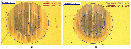
Figure 4.
Results of the ball-cratering (Calotest) method: (a) total thickness of the two-component architecture coating Cr/CrTiAl, (b) thickness of the outermost (CrTiAl)N layer of the three-component architecture coating Cr/(CrTiAl)N/CrTiAl.
To ensure representative mechanical property measurements without significant substrate influence, the maximum indentation depth during nanoindentation was limited to ≤10% of the respective coating thickness. Accordingly, appropriate loading conditions were selected for hardness (Hit) and elastic modulus (Eit) determination. The measured values of coating thickness, hardness, and elastic modulus are summarized in Table 2. These results enable direct comparison of the mechanical performance between the two-component and three-component architectures.
Table 2.
Results for thickness, hardness and the modulus of elasticity of coatings.
As can be observed from the results shown in Table 2, the depth of penetration of the indenter is less than 1/10 of the coating thickness, i.e., the load of 20 mN was carefully selected for the test. The measured hardness values of the applied coatings classify them as hard coatings, with a hardness greater than 20 GPa. Although the nitride coating has a significantly higher hardness, the elastic moduli of the two coatings are comparable.
Prior to the tribological tests, the surface roughness of the coated test specimens was measured. For the two-component architecture Cr/CrTiAl coating, the arithmetic mean roughness (Ra) values obtained from three representative measurements were 0.032 µm, 0.031 µm, and 0.042 µm. For the three-component architecture Cr/(CrTiAl)N/CrTiAl coating, the corresponding Ra values were 0.021 µm, 0.022 µm, and 0.024 µm. The recorded roughness values of a coated specimen with a single-architecture coating of Cr/CrTiAl (Ra 0.042 µm) and a coated specimen with a three-component architecture coating of Cr/(CrTiAl)N/CrTiAl (Ra 0.022 µm) are shown in Figure 5.
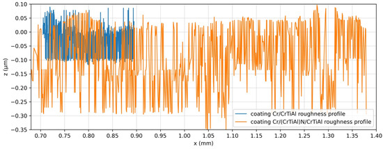
Figure 5.
Coatings Cr/CrTiAl and Cr/(CrTiAl)N/CrTiAl roughness curves.
During the tribological tests, data was obtained on the friction coefficient of the two coatings in a tribological system with 100Cr6 steel spheres in the ball-on-disc configuration. Concurrently, variations in the applied normal load were observed and documented throughout the test duration.
The data from the tribotester show the change in the loading force and the friction coefficient for a certain time. The test was conducted for a time of 5 min, corresponding to a friction path of 59 m. Representative raw recordings from the testing machine for the two-component architecture Cr/CrTiAl coating are presented in Figure 6. The recorded curves show a clearly pronounced smooth decrease in the friction force with an increase in the friction path. This behavior of the tribosystem can be explained by the gradual smoothing of the contact irregularities and a decrease in friction resistance. When the values of the normal load decrease, a linear increase in the friction coefficient is registered. The reduction of the force and the simultaneous increase in the friction coefficient is an effect that can be explained by a change in the effective contact geometry of the tribosystem. The obtained average friction coefficient value, μ = 0.362, indicates the onset of a more intense tribological regime, which is most likely accompanied by microplastic deformation. Figure 7 shows the data recorded by the testing machine for the Cr/(CrTiAl)N/CrTiAl three-component architecture coating, Figure 8a and Figure 8b show the processed data (smoothed or averaged) curves.
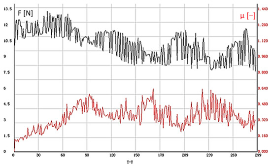
Figure 6.
Results from the testing machine for determining the friction coefficient μ for the Cr/CrTiAl two-component architecture coating (normal load F[N]-black curve, coefficient of friction μ[−]-red curve).
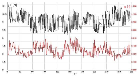
Figure 7.
Results from the testing machine for determining the friction coefficient μ for the Cr/(CrTiAl)N/CrTiAl three-component architecture coating (normal load F[N]-black curve, coefficient of friction μ[−]-red curve).
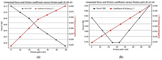
Figure 8.
Software-processed data results for determining the friction coefficient μ for the: (a) Cr/CrTiAl two-component architecture coating and the (b) Cr/(CrTiAl)N/CrTiAl three-component architecture coating (normal load F[N]-black curve, coefficient of friction μ[−]-red curve).
Tribological tests conducted on the three-component architecture Cr/(CrTiAl)N/CrTiAl coating revealed that the friction force remained nearly constant, with only minor fluctuations throughout the sliding duration, whereas the friction coefficient exhibited a very gradual increase characterized by a small positive slope. Such behavior is indicative of a stabilized friction regime in which the contact surfaces of the friction pair are already fitted and wear occurs evenly. The recorded values of the applied normal load and the corresponding friction coefficient displayed low dispersion, which is a clear manifestation of a highly stable tribological system with consistent contact conditions and minimal variability in wear mechanisms. The average friction coefficient for the three-component architecture coating was determined to be μ = 0.325. This value is modestly lower than that obtained for the two-component architecture Cr/CrTiAl coating (μ = 0.362), suggesting improved frictional performance attributable to the three-component architecture.
Following the tribological tests, the wear tracks on both coated specimens were profilometrically examined using the INSIZE ISR-C002 contact profilometer roughness tester. Cross-sectional profiles of the wear scars were acquired to quantify wear morphology, including track depth, width, and volume loss. A representative profile of the wear track on the two-component architecture Cr/CrTiAl coating is presented in Figure 9, whereas the corresponding profile for the three-component architecture Cr/(CrTiAl)N/CrTiAl coating is shown in Figure 10.
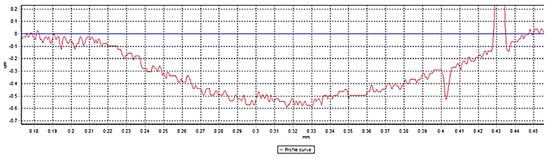
Figure 9.
Wear track profile of the Cr/CrTi coating.
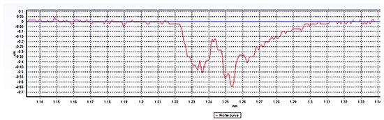
Figure 10.
Wear track profile of the Cr/(CrTiAl)N/CrTiAl coating.
To determine the wear rate (k) of the two studied coatings, their worn volume during the friction process was calculated. Using the SolidWorks Premium 2025 SP1.2 software, the geometric model of the test specimens was built. The cross-section of the wear track was copied at a 1:1 scale (Figure 11 and Figure 12), after which, for higher accuracy along the three diameters (maximum, average and minimum), the registered cross-section was converted into the removed volume of the coating. The size of the cross-section (mm2) was determined with the “Section properties” command, and the removed volume (mm3) was determined with the “Mass properties” command. Table 3 shows the results obtained for the size of the cross-section of the track and the worn volumes of the coatings.
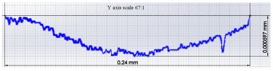
Figure 11.
Graphical model of the cross-section of the wear track of a Cr/CrTiAl coating.
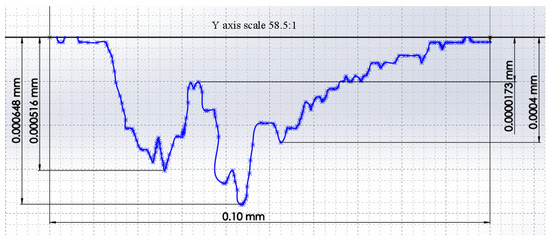
Figure 12.
Graphical model of the cross-section of the wear track of a Cr/(CrTiAl)N/CrTiAl coating.
Table 3.
Results for the size of the track cross-section and the worn volumes of the coatings.
After determining the worn volumes of the two coatings, their wear rate () was calculated using Formula (1), where the worn volume is V (mm3), the normal load is F [N], and the friction distance is S [m], as follows:
The obtained results show that the three-component architecture nitride coating Cr/(CrTiAl)N/CrTiAl has a lower wear rate (1.64 × 10⁻⁴) compared to the two-component architecture coating Cr/CrTiAl, which has a wear rate of 7.6 × 10⁻⁴.
4. Discussion
The results obtained from the adhesion test performed in accordance with EN ISO 26443, European Standard, Bulgarian Institute for Standardization, Sofia, Bulgaria, 19 February 2014 [38] demonstrated that no delamination or spallation occurred for either the two-component architecture Cr/CrTiAl or the three-component architecture Cr/(CrTiAl)N/CrTiAl, and their degree of adhesion was classified as class HF1, representing the highest level of interfacial integrity within the HF1–HF6 grading scale, where minimal or no circumferential cracking and negligible cohesive/adhesive failure is observed.
Distinct crack morphologies were evident in the indentation craters, attributable to the structural differences between the coatings. In the two-component architecture Cr/CrTiAl coating, the resulting crack had a spiral nature from the surface of the coating in depth, without other branches. This characteristic is ascribed to the homogeneous metallic/ternary composition, which facilitates stress relaxation through extended crack paths without significant deflection at interfaces. Conversely, the three-component architecture Cr/(CrTiAl)N/CrTiAl coating displayed cracks in the coating in the contact zone, most likely due to the presence of several layers, but no cracks of critical dimensions leading to chipping or delamination were detected, confirming robust interfacial bonding and the efficacy of the three-component architecture design in dissipating deformation energy. These superior adhesion characteristics, combined with the balanced mechanical properties of the QT-treated 42CrMo4 substrate, indicate that the investigated coatings are likely to enhance the operational durability of components subjected to simultaneous wear and dynamic loading. Therefore, the integration of quenching and high-temperature tempering (QT) with these PVD coatings is expected to improve the tribomechanical performance of 42CrMo4 steel parts in demanding service environments.
According to the measured hardness values of the two coatings, 27.3 GPa (Cr/CrTiAl) and 37.5 GPa (Cr/(CrTiAl)N/CrTiAl), they can be classified as hard coatings (hardness greater than 20 GPa). Of interest are the measured values of the elastic modulus, Eit = 353 GPa for the two-component architecture coating and Eit = 349 GPa for the three-component architecture coating. Despite the difference in hardness, the two coatings have comparable elastic modulus values. The values of elastic modulus (Eit) of the coatings provides a basis for assuming that the two-component architecture coating is suitable for use as a softer intermediate layer between the two hard nitride layers in the Cr/(CrTiAl)N/CrTiAl coating. Our assumptions are based on the fact that the identical elastic modulus of the intermediate (soft) and hard nitride layers will contribute to the uniform distribution of stresses between the two layers under an applied external load. This, in turn, will reduce the possibility of the occurrence of high internal stresses in both structures, which could cause deformation and destruction of the coating. This reasoning is also confirmed by the positive results of the adhesion test. The two-component architecture Cr/CrTiAl coating has a high hardness value (27.3 GPa), a comparable modulus of elasticity as the studied nitride coating and excellent adhesion, which is a prerequisite for its use as a stand-alone structure (monolayer coating) in real operating conditions.
To determine the µ of both coatings, tribological tests were conducted using the presented methodology. The plots from the test of the two-component architecture Cr/CrTiAl coating show that at the beginning of the friction, the normal load increases, which is most likely due to the resistance exerted by the material during the activation of the tribological system, and the value of the friction coefficient also increases. After about 12 m of friction, the force decreases to the set values, and the value of the coefficient continues to increase. After the activation of the system and until the end of the test, a tendency is observed for a gradual decrease in the loading force and a gradual increase in the µ values. This behavior of the tribosystem can be explained by the gradual smoothing of the contact irregularities and a decrease in the friction resistance. When the values of the normal load decrease, a linear increase in the friction coefficient is registered. The decrease in the force and the simultaneous increase in the friction coefficient is an effect that can be explained by a change in the effective contact geometry of the tribosystem. The maximum (μ = 0.637), minimum (μ = 0.1169) and average value (μ = 0.362) of the friction coefficients during the test process were registered. The change in the normal load during the test process is also characterized by a maximum and a minimum, with Fmax = 13.31 N and Fmin = 7.73 N. The average value of the applied load was F = 10.23 N. The registered results indicate the onset of a more intense tribological regime, most likely accompanied by microplastic deformation.
At the beginning of the tribological testing process of the three-component architecture coating (Cr/(CrTiAl)N/CrTiAl), an increase in the loading force was again registered, but for a very short time interval (friction path ≈ 3 m), unlike the two-component architecture coating, after which an increase in the loading force was again registered. The initial increase in force during the test was due to the resistance arising from contact between the friction bodies and the test body. The subsequent decrease in force after about 3 m of friction path may be due to either very intense wear of the contact surfaces of the spheres used and/or deformation of the friction bodies due to the greater hardness of the coating. After reducing the loading force, it was found that it increased again for a very short period of time (friction path), which was accompanied by a decrease in the friction coefficient, which was most likely due to adjustment of the friction system. After this period of time until the end of the test, a slight change in the loading force was registered around an almost constant value, and the friction coefficient increased with a very small slope. Such behavior is typical for a friction system in such a friction regime, in which the contact surfaces of the system are already matched and the wear proceeds evenly. The minimum, maximum and average values of F (Fmin = 6.59 N, Fmax = 12.11 N, and F = 9.25 N, respectively) and µ (µmin = 0.195, µmax = 0.66, and µ = 0.325, respectively) were recorded. The average values of the applied force and the friction coefficient were low-dispersed, which is a sign of a stable tribological system. The obtained value of the friction coefficient μ = 0.325 of the three-component architecture coating Cr/(CrTiAl)N/CrTiAl was slightly lower than the value of μ = 0.362 in the two-component architecture coating Cr/CrTiAl.
To determine the wear rate () of both coatings, their wear traces after the tribological tests were examined. In the case of the two-component architecture Cr/CrTiAl coating, the wear was uniform and had a significantly larger width of the trace. A slight change in the trace profile was observed at the maximum penetration depth. This is probably due to the more intensive wear of the spheres at the beginning of the test, when their contact area is significantly smaller and the test body has a higher hardness (27.3 GPa) compared to the spheres (830HV0.1). The behavior of the friction system during testing, as well as the profile of the registered wear trace of the test bodies, supports the occurrence of a more intense tribological process and microplastic deformation. A probable reason for this is the lower hardness of the Cr/CrTiAl coating compared to the studied three-component architecture nitride coating. The profile of the Cr/(CrTiAl)N/CrTiAl coating track differs from the profile of the studied two-component architecture coating. The width of the wear track is smaller and the wear profile is not uniform. Two valleys were registered, and the wear was greater from the inner part. The reasons for the appearance of the two peaks in depth may be deformation and/or wear in the contact area of the friction bodies and a change in their geometry (during the operation of the system) due to the high hardness of the coating (Hit = 37.5 GPa). This assumption is due to the registered changes in the normal load (F) and the friction coefficient (μ) in the process of tribological testing. It is also possible that wear material accumulates around the contact zone of the friction bodies, but this is the less likely reason. The reason for greater wear on the inside of the track is most likely due to the concentration of wear material in this part of the tribosystem, which, in turn, leads to more intensive wear of the coating in this zone. This assumption is related to the conditions of the test, namely dry friction. In the absence of a lubricant, the possibility of removing the worn material from both the hard coating and the friction bodies is minimized. In turn, this accumulated wear material complicates the operation of the friction system and affects the wear of the spheres and the test body in the areas where it concentrates. In this particular case, the concentration of worn material is clearly on the inner part of the track, and this is the basis for greater wear in this friction zone.
The investigated coatings have hardness, modulus of elasticity and friction coefficient values comparable to those of nitride (two-component architecture and three-component architecture) coatings, and their wear rate also corresponds to generally accepted values [44,45,46,47,48,49,50,51,52,53].
5. Conclusions
- The mechanical properties, friction coefficient and wear rate of the three-component architecture nitride coating Cr/(CrTiAl)N/CrTiAl make it a competitive alternative to the two-component architecture and three-component architecture nitride coatings used.
- The results of this research on the two-component architecture coating Cr/CrTiAl support its recommendation for use as both as an intermediate soft layer in hard coatings and as an independent structure, depending on the operating conditions of the base material.
- The monolayer coating demonstrates excellent adhesion to the substrate used, and the comparable values of the elastic modulus of both coatings are the basis for the registered class HF1 adhesion of the three-component architecture coating Cr/(CrTiAl)N/CrTiAl.
- The conducted experiments contribute an additional insight into the research on improving the operational properties of mechanical engineering materials. The possibility of applying hard, wear-resistant coating at lower operating temperatures (230–250 °C) without affecting the initial structure (and thus the properties) of the substrate provides a basis for creating components that operate under wear and dynamic load conditions.
- Other advantages of the presented method for surface modification of materials with increased plasticity and toughness, compared to conventional methods of chemical-thermal treatment (carburizing, nitriding, ion-nitriding, nitrocarburizing, etc.), include a significantly shorter process duration, minimizing the possibility of deformations, and eliminating the need for a subsequent heat treatment process (cementation).
- In industrial applications, components typically have larger surface areas and more complex geometries, which may lead to local variations in coating properties. However, such variations are generally confined to limited regions and do not affect the overall coating performance. In contrast, coating evaluation is commonly conducted using small, simply shaped coupons. These specimens are sufficient for reliable coating characterization and are appropriately sized for laboratory and research equipment, making them a valid and widely accepted approach for experimental investigations.
Author Contributions
Conceptualization, Y.S., B.D., G.T. and K.M.; methodology, K.M., Y.S., V.M., A.N., R.D., M.A., K.P. and M.Y.; software, B.D., V.M., K.P. and A.N.; validation, B.D., R.D., V.M., K.P. and A.N.; formal analysis, Y.S., R.D., M.A. and M.Y.; investigation, G.T., K.M. and Y.S.; resources, G.T. and K.M.; data curation, M.Y. and M.A.; writing—original draft preparation, B.D., R.D., V.M., K.P. and A.N.; writing—review and editing, B.D. and Y.S.; visualization, B.D., M.Y. and M.A.; supervision, K.M. and G.T.; project administration, G.T., K.M. and Y.S.; funding acquisition, G.T., K.M. and Y.S. All authors have read and agreed to the published version of the manuscript.
Funding
This work was accomplished with financial support from the European Regional Development Fund within the Operational Programme “Bulgarian national recovery and resilience plan”, under the procedure for direct provision of grants “Establishing of a network of research higher education institutions in Bulgaria”, and within Project BG-RRP-2.004-0005, “Improving the research capacity anD quality to achieve intErnAtional recognition and reSilience of TU-Sofia (IDEAS)”.
Data Availability Statement
The original contributions presented in this study are included in the article. Further inquiries can be directed to the corresponding authors.
Acknowledgments
The equipment for this study was funded by the European Regional Development Fund under the “Research Innovation and Digitization for Smart Transformation” program 2021–2027, and under Project BG16RFPR002-1.014-0006, “National Centre of Excellence Mechatronics and Clean Technologies”.
Conflicts of Interest
The authors declare no conflicts of interest.
Abbreviations
| PVD | Physical vapor deposition |
| DCMS | Direct Current Magnetron Sputtering |
| µ | Coefficient of friction |
References
- Atay, G.Y.; Bilgiç, N. Investigation of the Microstructure and Mechanical Properties of Heat-Treated 42CrMoS4 Steel. J. Mater. Eng Perform 2024, 33, 13265–13273. [Google Scholar] [CrossRef]
- Hanza, S.S.; Štic, L.; Liverić, L.; Špada, V. Corrosion behaviour of tempered 42CrMo4 steel. Mater. Tehnol. 2021, 55. [Google Scholar] [CrossRef]
- Zhang, Y.; Zhao, H.; Liu, P.; Wei, M.; Lu, Y.; Liu, Z. Effect of tempering temperature on the microstructure and mechanical properties of 42CrMo4 steel. J. Phys. Conf. Ser. 2023, 2459, 012044. [Google Scholar] [CrossRef]
- Ulrich, C.; Günther, S.; Becker, N.; Schubert, V.; Vetter, B.; Leyens, C. High strength tempered 42CrMo4 for shafts in drive technology. Forsch Ingenieurwes 2025, 89, 59. [Google Scholar] [CrossRef]
- Thakare, A.S.; Butee, S.P.; Kamble, K.R. Improvement in Mechanical Properties of 42CrMo4 Steel Through Novel Thermomechanical Processing Treatment. Metallogr. Microstruct. 2020, 9, 759–773. [Google Scholar] [CrossRef]
- Ramesh, G.; Surendarnath, S.; Ramesh Kumar, S. Influence of Quenching Conditions on Microstructure Evolution and Hardness of 42CrMo4 Alloy Steel. J. Mines Met. Fuels 2024, 71, 441–446. [Google Scholar] [CrossRef]
- Imdad, A.; Arniella, V.; Zafra, A.; Belzunce, J. Tensile behaviour of 42CrMo4 steel submitted to annealed, normalized, and quench and tempering heat treatments with in-situ hydrogen charging. Int. J. Hydrog. Energy 2024, 50 Pt A, 270–280. [Google Scholar] [CrossRef]
- Çeltik, C.; Yürektürk, Y. Microstructure and wear properties of 42crmo4 steel prepared by various heat treatments methods. Conf. Met. 2022, 388–394. [Google Scholar] [CrossRef]
- Çalık, A.; Dokuzlar, O.; Uçar, N. The effect of heat treatment on mechanical properties of 42CrMo4 steel. J. Achiev. Mater. Manuf. Eng. 2020, 98, 7. [Google Scholar] [CrossRef]
- Szala, M.; Winiarski, G.; Wójcik, Ł.; Bulzak, T. Effect of Annealing Time and Temperature Parameters on the Microstructure, Hardness, and Strain-Hardening Coefficients of 42CrMo4 Steel. Materials 2020, 13, 2022. [Google Scholar] [CrossRef]
- Zhang, Z.; Wang, D.; Liu, G.; Qian, Y.; Xu, Y.; Xiang, D. Surface Modification of 42CrMo Steels: A Review from Wear and Corrosion Resistance. Coatings 2024, 14, 337. [Google Scholar] [CrossRef]
- Sola, R.; Poli, G.; Veronesi, P.; Giovanardi, R. Effects of Surface Morphology on the Wear and Corrosion Resistance of Post-Treated Nitrided and Nitrocarburized 42CrMo4 Steel. Metall. Mater. Trans. A 2014, 45, 2827–2833. [Google Scholar] [CrossRef]
- Kusmic, D.; Van Thanh, D. Tribological and corrosion properties of plasma nitrided and nitrocarburized 42CrMo4 steel. IOP Conf. Ser. Mater. Sci. Eng. 2016, 179, 012046. [Google Scholar] [CrossRef]
- Liu, C.; Li, C.; Suo, Z.; Jiang, F.; Gu, J. Investigation of microstructural evolution and its effect on wear and corrosion behavior of 42CrMo steel before and after plasma nitriding at different temperature. Surf. Topogr. Metrol. Prop. 2025, 13, 4. [Google Scholar] [CrossRef]
- Yıldız, U.T.; Varol, T.; Day, B.B.; Kandemir, B.; Alptekin, F.; Günaçar, A.F. Surface improvement of 42CrMo4 low alloy steel via nitrocarburization and electroless Ni-P plating: Enhancing the surface hardness. Int. J. Mater. Eng. Technol. 2024, 7, 18–21. [Google Scholar]
- Panfil-Pryka, D.; Kulka, M.; Kotkowiak, M.; Michalski, J.; Grochalski, K. Tribological Behavior of Gas-Nitrided 42CrMo4 Steel at Elevated Temperatures. Coatings 2025, 15, 18. [Google Scholar] [CrossRef]
- Dobrocky, D.; Pokorny, Z.; Joska, Z.; Sedlak, J.; Zouhar, J.; Majerik, J.; Studeny, Z.; Prochazka, J.; Barenyi, I. Change in Dimensions and Surface Roughness of 42CrMo4 Steel after Nitridation in Plasma and Gas. Coatings 2022, 12, 1481. [Google Scholar] [CrossRef]
- Sommer, M.; Hoja, S.; Steinbacher, M.; Fechte-Heinen, R. Investigation of Compound Layer Structures after Nitriding and Nitrocarburizing of Quenched and Tempered Steels. HTM J. Heat Treat. Mater. 2021, 76, 219–236. [Google Scholar] [CrossRef]
- Chen, H.; Chen, T.-C.; Hsu, H.-H.; Tsay, L.-W. Effect of Microstructure and Compressive Residual Stress on the Fatigue Performance of AISI 4140 Steel with QPQ Salt-Bath Nitro-Carburizing. Materials 2025, 18, 1995. [Google Scholar] [CrossRef]
- Panfil-Pryka, D.; Kulka, M.; Makuch, N.; Michalski, J.; Dziarski, P. The Effect of Temperature Distribution during Laser Heat Treatment of Gas-Nitrided 42CrMo4 Steel on the Microstructure and Mechanical Properties. Coatings 2020, 10, 824. [Google Scholar] [CrossRef]
- Moneta, M.; Stodolny, J.; Michalkiewicz, B.; Wróbel, R.J. Influence of Surface Roughness on the Properties of Nitrided Layer on 42CrMo4 Steel. Materials 2023, 16, 4496. [Google Scholar] [CrossRef]
- Maximov, J.; Duncheva, G.; Anchev, A.; Dunchev, V.; Anastasov, K.; Ichkova, M. Sustainable Combined Process for Improving Surface Integrity and Fatigue Strength of Heat-Treated 42CrMo4 Steel Shafts and Axles. Metals 2025, 15, 755. [Google Scholar] [CrossRef]
- Navinsek, B.; Panjan, P.; Milosev, I. PVD coatings as an environmentally clean alternative to electroplating and electroless processes. Surf. Coat. Technol. 1999, 116–119, 476–487. [Google Scholar] [CrossRef]
- Fotovvati, B.; Namdari, N.; Dehghanghadikolaei, A. On coating techniques for surface protection: A Review. J. Manuf. Mater. Process. 2019, 3, 28. [Google Scholar] [CrossRef]
- Garg, R.; Gonuguntla, S.; Saddam, S.K.; Iqbal, M.; Dada, A.; Pal, U.; Ahmadipour, M. Sputtering thin films: Materials, applications, challenges and future directions. Adv. Colloid Interface Sci. 2024, 33, 103203. [Google Scholar] [CrossRef]
- Kelly, P.; Arnell, R. Magnetron sputtering: A review of recent developments and applications. Vacuum 2000, 56, 159–172. [Google Scholar] [CrossRef]
- Azouaoui, A.; Benzakour, N.; Hourmatallah, A.; Bouslykhane, K. Structural and Magnetic Properties of CrN: Investigated by First-Principles Calculations, Monte Carlo Simulation, and High-Temperature Series Expansions. J. Supercond. Nov. Magn. 2020, 33, 3113–3120. [Google Scholar] [CrossRef]
- Merie, V.; Negrea, G.; Pustan, M.; Birleanu, C.; Neamtu, B. Tribomechnical characteristics of chromium nitride thin films deposited at different parameters. Rom. J. Tech. Sciences. Appl. Mech. 2019, 64, 57–72. [Google Scholar]
- Ruden-Munoz, A.; Parra, E.; Sequeda, F. CrN coatings deposited by magnetron sputtering: Mechanical and tribological properties. Dyna (Medellin Colomb.) 2015, 82, 147–155. [Google Scholar] [CrossRef]
- Martev, I.; Dechev, D.; Ivanov, N.; Uzunov, T.; Kashchieva, E. Characterization and properties of highly adhesive titanium nitride and tungsten nitride thin films. J. Phys. Conf. Ser. 2008, 113, 012025. [Google Scholar] [CrossRef]
- Samani, M.; Chen, G.; Ding, X.; Zeng, X. Thermal conductivity of CrAlN and TiAlN coatings deposited by lateral rotating cathode arc. Key Eng. Mater. 2010, 447–448, 705–709. [Google Scholar] [CrossRef]
- Jianxin, D.; Fengfang, W.; Yunsong, L.; Youqiang, X.; Shipeng, L. Erosion wear of CrN, TiN, CrAlN, and TiAlN PVD nitride coatigns. Int. J. Refract. Met. Hard Mater. 2012, 35, 10–16. [Google Scholar] [CrossRef]
- BDS EN ISO 683-2:2018; Heat-Treatable Steels, Alloy Steels and Free-Cutting Steels—Part 2: Alloy Steels for Quenching and Tempering. European Standard: Brussels, Belgium, 2018.
- Dochev, B.; Dimova, D.; Trojan, K.; Čapek, J.; Kamarska, K.; Chuchulska, B. Investigation of the Influence of Alloying Elements Ni, Cr, Co and Mo on the Crystallization Process, Phase Composition and Corrosion Resistance of AlSi25Cu4Cr and AlSi25Cu5Cr Alloys. Materials 2025, 18, 907. [Google Scholar] [CrossRef] [PubMed]
- BDS EN ISO 6508-1:2024; Metallic Materials—Rockwell Hardness Test—Part 1: Test method (ISO 6508-1:2023). Bulgarian Institute for Standardization: Sofia, Bulgaria, 2024.
- Dochev, B.; Sofronov, Y.; Mishev, V.; Nikolov, A.; Petrov, K.; Angelov, M.; Yordanov, M.; Todorov, G.; Marchev, K. Deposition of Multilayer Nanostructured Coating Cr/(Cr/a-C)ml on Alloy Steels. Materials 2025, 18, 4923. [Google Scholar] [CrossRef] [PubMed]
- Mishev, V.; Sofronov, Y.; Yordanov, M.; Nikolov, A.; Petrov, K.; Dimitrova, R.; Angelov, M.; Dochev, B.; Marchev, K.; Todorov, G. Deposition and Properties of Nanostructured Multilayer Cr/(Cr/a-C)ml Coating on Stainless Steels. Materials 2025, 18, 5654. [Google Scholar] [CrossRef] [PubMed]
- BDS EN ISO 26423:2016; Fine Ceramics (Advanced Ceramics, Advanced Technical Ceramics)—Determination of Coating Thickness by Crater-Grinding Method. Bulgarian Institute for Standardization: Sofia, Bulgaria, 2016.
- ISO 26423:2009; Fine Ceramics (Advanced CERAMICS, advanced Technical Ceramics)—Determination of Coating Thickness by Crater-Grinding Method. International Standard: Geneva, Switzerland, 2009.
- Chitanov, V.; Zlatareva, E.; Kolchev, S.; Cholakova, T.; Kolaklieva, L.; Kakanakov, R.; Pashinski, C. Investigation of properties of novel multilayer Cr/CrN/CrTiN/CrTiAlN hard coating with four bilayers. In Journal of Physics: Conference Series; IOP Publishing: Bristol, UK, 2024; Volume 2710, ISSN 1742-6596. [Google Scholar] [CrossRef]
- Chitanov, V.; Kolaklieva, L.; Kakanakov, R.; Cholakova, T.; Pashinski, C.; Kolchev, S.; Zlatareva, E.; Atanasova, G.; Tsanev, A.; Hingerl, K. Investigation of Optical Properties of Complex Cr-Based Hard Coatings Deposited through Unbalanced Magnetron Sputtering Intended for Real Industrial Applications. Coatings 2024, 14, 946. [Google Scholar] [CrossRef]
- Georgiev, K. Statistical analysis of the quality of a technological process for the production of shafts for electric motors by roughness study. In Environment. Technology. Resources. Proceedings of the International Scientific and Practical Conference, Rezekne, Latvia, 27–28 June 2024; Rezekne Academy of Technologies: Rēzekne, Latvia, 2024; Volume 3, pp. 70–74. [Google Scholar] [CrossRef]
- Georgiev, K.; Katsarova, P. Comparative analysis of the resultsof an experimental study with basic equipment and a specially made one tothe insize isr-c002 roughness tester. In Environment. Technology. Resources. Proceedings of the International Scientific and Practical Conference, Rezekne, Latvia, 27–28 June 2024; Rezekne Academy of Technologies: Rēzekne, Latvia, 2024; Volume 3, pp. 58–64. [Google Scholar] [CrossRef]
- Muktanova, N.; Rakhadilov, B.; Naimankumaruly, E.; Kalitova, A. Structural and Phase Characteristics and Properties of Multilayer Cr/CrN Coatings Obtained by Magnetron Sputtering. Coatings 2025, 15, 1375. [Google Scholar] [CrossRef]
- Martínez, E.; Romero, J.; Lousa, A.; Esteve, J. Wear behavior of nanometric CrN/Cr multilayers. Surf. Coat. Technol. 2003, 163–164, 571–577. [Google Scholar] [CrossRef]
- Lackner, J.M.; Waldhauser, W.; Major, L.; Kot, M. Tribology and Micromechanics of Chromium Nitride Based Multilayer Coatings on Soft and Hard Substrates. Coatings 2014, 4, 121–138. [Google Scholar] [CrossRef]
- Polcar, T.; Martinez, R.; Vítů, T.; Kopecký, L.; Rodriguez, R.; Cavaleiro, A. High temperature tribology of CrN and multilayered Cr/CrN coatings. Surf. Coat. Technol. 2009, 203, 3254–3259. [Google Scholar] [CrossRef]
- Hainsworth, S.V.; Soh, W.C. The effect of the substrate on the mechanical properties of TiN coatings. Surf. Coat. Technol. 2003, 163–164, 515–520. [Google Scholar] [CrossRef]
- Chou, W.; Yu, G.; Huang, J. Mechanical properties of TiN thin film coatings on 304 stainless steel substrates. Surf. Coat. Technol. 2002, 149, 7–13. [Google Scholar] [CrossRef]
- Ming’e, W.; Guojia, M.; Xing, L.; Chuang, D. Morphology and Mechanical Properties of TiN Coatings Prepared with Different PVD Methods. Rare Met. Mater. Eng. 2016, 45, 3080–3084. [Google Scholar] [CrossRef]
- Cheng, Y.H.; Browne, T.; Heckerman, B.; Bowman, C.; Gorokhovsky, V.; Meletis, E.I. Mechanical and tribological properties of TiN/Ti multilayer coating. Surf. Coat. Technol. 2010, 205, 146–151. [Google Scholar] [CrossRef]
- Yuan, Z.; Han, Y.; Zang, S.; Chen, J.; He, G.; Chai, Y.; Yang, Z.; Fu, Q. Analysis of the mechanical properties of TiN/Ti multilayer coatings using indentation under a broad load range. Ceram. Int. 2021, 47, 10796–10808. [Google Scholar] [CrossRef]
- Chen, L.; Du, Y.; Wang, S.Q.; Wang, A.J.; Xu, H.H. Mechanical properties and microstructural evolution of TiN coatings alloyed with Al and Si. Mater. Sci. Eng. A 2009, 502, 139–143. [Google Scholar] [CrossRef]


Disclaimer/Publisher’s Note: The statements, opinions and data contained in all publications are solely those of the individual author(s) and contributor(s) and not of MDPI and/or the editor(s). MDPI and/or the editor(s) disclaim responsibility for any injury to people or property resulting from any ideas, methods, instructions or products referred to in the content. |
© 2026 by the authors. Licensee MDPI, Basel, Switzerland. This article is an open access article distributed under the terms and conditions of the Creative Commons Attribution (CC BY) license.