Review

A State-of-the-Art Review on Metallic Hysteretic Dampers: Design, Materials, Advanced Modeling, and Future Challenges

1
Department of Mechanical Engineering, Universidad de La Frontera, Temuco 4811230, Chile
2
Construction Multidisciplinary Research Group, Facultad de Arquitectura, Construcción y Medio Ambiente, Universidad Autónoma de Chile, Talca 3460000, Chile
3
Departamento de Obras Civiles, Facultad de Ciencias de la Ingeniería, Universidad Católica del Maule, Talca 3460000, Chile
*
Author to whom correspondence should be addressed.
Metals 2026, 16(2), 161; https://doi.org/10.3390/met16020161
Submission received: 19 November 2025 / Revised: 13 December 2025 / Accepted: 17 December 2025 / Published: 29 January 2026

Abstract

Metallic seismic dampers are an effective tool for reducing structural damage during seismic events. While previous reviews have often focused on cataloging device types, this review presents a deep analysis of the underlying science governing their performance. Particular emphasis is placed on advanced computational methods, such as non-linear kinematic hardening (e.g., Chaboche) and micromechanical damage models (e.g., GTN), which are essential for accurately predicting low-cycle fatigue and fracture. Furthermore, advances in materials science are analyzed, ranging from low-yield-strength (LYS) steels to self-centering shape memory alloys (SMAs). Finally, the influence of manufacturing processes (including additive manufacturing) is explored, and critical future challenges in design, modeling, and long-term durability are identified. This analysis provides a foundational resource for researchers seeking to advance beyond simple phenomenological design toward physics-based prediction of damper performance.

1. Introduction

Earthquakes are one of the natural phenomena with the greatest destructive potential, causing significant human and economic losses. In recent years, events in Chile (2010) and Japan (2011) resulted in costs of approximately $30 billion and $300 billion, respectively [1]. These events have driven the development of technologies aimed at improving the seismic response of structures, among which energy dissipation devices stand out for their effectiveness and relatively low cost. Dissipation systems are classified as passive, active, semi-active, and hybrid [2]. Among these, passive systems are the most widely used due to their simplicity, reliability, and lack of external energy requirements. Within this group, hysteretic metal dampers, which operate through cyclic plastic deformation of the material, are particularly attractive for buildings and bridges located in areas of high seismicity [3,4].
In recent decades, there has been an unprecedented effort to improve the seismic resilience of structures through the integration of supplementary energy dissipation devices. The 2023 Turkey-Syria and 2021 Haiti earthquakes demonstrated, once again, that conventional strength-based design strategies are insufficient to prevent functional collapse, even when the safety of people is ensured [5,6]. In this context, metallic hysteretic dampers have become established as one of the most reliable and cost-effective technologies for protecting structural systems from excessive deformation and damage [7,8]. These devices have been widely applied in high-rise buildings, bridges, and industrial facilities due to their robustness, stable hysteretic response, and ease of replacement after major earthquakes [9,10]. Furthermore, advances in computational mechanics and additive manufacturing have enabled the design of geometrically optimized dampers capable of achieving superior energy dissipation-to-weight ratios [11,12] and greater fatigue resistance [13]. Despite these achievements, significant gaps remain in our understanding of how geometric parameters, material constitutive laws, and manufacturing imperfections interact to determine the overall hysteretic behavior of metallic dampers [7,14]. Addressing these knowledge gaps is crucial for advancing performance-based design methodologies and developing next-generation seismic protection systems that ensure both safety and long-term resilience.
The U-shaped metal dissipator was originally proposed by Kelly, Skinner, and Heine (1972) as an element capable of dissipating energy through the cyclic bending of its metal arms [15]. Since then, various geometric modifications have been developed to improve its performance. Ebadi Jamkhaneh et al. (2019) introduced a version with symmetrically closed ends, demonstrating that material thickness directly influences dissipation capacity and resistance to loss of stiffness [16]. Subsequently, Qiu et al. (2023) proposed the incorporation of perpendicular ribs of different dimensions, improving the overall stiffness and strength of the system [17]. For its part, Nippon Steel Corporation commercially developed the UD-40 model, characterized by its greater thickness and lower width-to-length ratio, demonstrating highly stable behavior under cyclic loads without fracture during a single seismic event [18].
In this way, the present article aims to review and synthesize the most relevant advances in the numerical simulation of U-shaped metal dissipators, analyzing the different approaches to computational modeling, convergence, and parameterization criteria, as well as the evolution of hysteretic behavior in two-dimensional and three-dimensional models. It also presents and discusses the new classification developed, evaluating its relevance compared to the traditional criteria used in the technical literature. Thus, this review highlights critical knowledge gaps in the design, selection, and application of dampers, particularly in the accurate prediction of damper performance and behavior, which require further research. Distinct from previous literature focused on device cataloging, the present work synthesizes advances in modeling approaches and emerging design strategies (such as advanced materials and additive manufacturing), explicitly addressing outstanding issues for long-term implementation. This approach ensures a high level of novelty and scientific contribution, not only summarizing the current state-of-the-art but also clearly identifying areas for improvement to advance the field.
Unlike previous review articles that focus primarily on cataloging existing damper geometries or summarizing experimental trends, this manuscript introduces several elements of scientific novelty. First, it proposes a functional taxonomy that differentiates between applied loads and dissipated loads, providing a mechanistic classification that directly supports performance-based design. Second, it synthesizes advanced constitutive modeling approaches, such as nonlinear kinematic hardening, micromechanical damage formulations, and phase-field fracture modeling, which have not previously been integrated into a unified review of metallic dampers. Finally, this work critically identifies unresolved knowledge gaps in material behavior, fatigue prediction, model calibration, and manufacturing-induced imperfections, thereby establishing a comprehensive framework for future research. These contributions differentiated the present study from the existing literature, providing a physics-based perspective for the development of next-generation dampers. This article is organized as follows: Section 2 presents the fundamental principles of seismic energy dissipation and the need for structural resilience. Section 3 reviews the classifications and working principles of major metallic damper families (flexural, shear, axial, and torsional) to provide essential context. From there, the paper analyzes the underlying science governing performance: Section 4 examines high-performance materials, from low-yield-strength (LYS) steels to shape memory alloys (SMAs). Section 5 constitutes the technical core of the article, detailing the advanced computational methods—such as non-linear kinematic hardening and micromechanical damage models—required to accurately predict cyclic behavior. Section 6 explores the influence of manufacturing processes (conventional and additive) on device performance. Section 7 identifies critical challenges and future research directions arising from these areas. Finally, Section 8 presents the conclusions.

2. Seismic Energy Dissipation

2.1. The Need for Enhanced Structural Resilience

Seismic activity represents one of the most significant natural hazards, capable of causing substantial human and economic losses due to widespread damage and the collapse of buildings and infrastructure. Historically, the primary goal of seismic design was human safety, an approach that accepted significant structural damage as a necessary consequence of dissipating the energy imparted by an earthquake, provided that catastrophic collapse was avoided [19]. While this method has saved countless lives, the social and economic costs associated with post-earthquake repair, business disruption, and displacement have highlighted its limitations [20]. This realization has led to a fundamental shift in seismic engineering, moving from the conventional strength-based approach to a Performance-Based Design (PBD) framework [21]. The central principle of PBD is to achieve specific and predictable performance objectives, such as immediate occupancy or operational continuity, under different levels of seismic hazard. This approach reframes the engineering problem: the goal is not simply to prevent collapse, but to actively control damage, minimize financial losses, and improve the overall resilience of communities, allowing for the continued use of a building without interruption after a seismic event [22].

2.2. Evolution of Seismic Protection Systems

To achieve the objectives of the PBD, structural engineering has developed various seismic protection technologies, generally categorized as structural control systems. These systems can be classified, according to their energy requirements and control strategy, into passive, active, semi-active, and hybrid systems [2]. Active systems use external energy to drive actuators that apply counterbalancing forces to the structure, while semi-active systems use a small amount of energy to modify the properties of damping devices in real time. While powerful, these systems’ dependence on external energy and complex control algorithms can represent a vulnerability during a seismic event, where the energy supply is often compromised [23].
In contrast, passive control systems do not require an external energy source, activating only in response to the movement of the structure itself [23]. Their simplicity, reliability, and cost-effectiveness have made them the most widely adopted solution for seismic protection [23]. The fundamental concept for most passive systems is that of supplemental energy dissipation. Instead of allowing seismic energy to be absorbed through widespread and uncontrolled damage to primary structural elements (e.g., beams and columns), energy dissipation devices (EDDs) or specially designed dampers are strategically incorporated into the structure [24]. These devices are designed to absorb the vast majority of incoming seismic energy, acting as sacrificial fuses that can be inspected and replaced after a severe (design level) or extreme (maximum credible) earthquake. This strategy allows the main load-bearing structure to remain essentially elastic and largely intact, thus achieving the BDP’s objective of operational continuity [25].
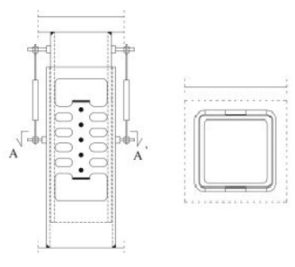
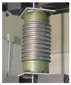
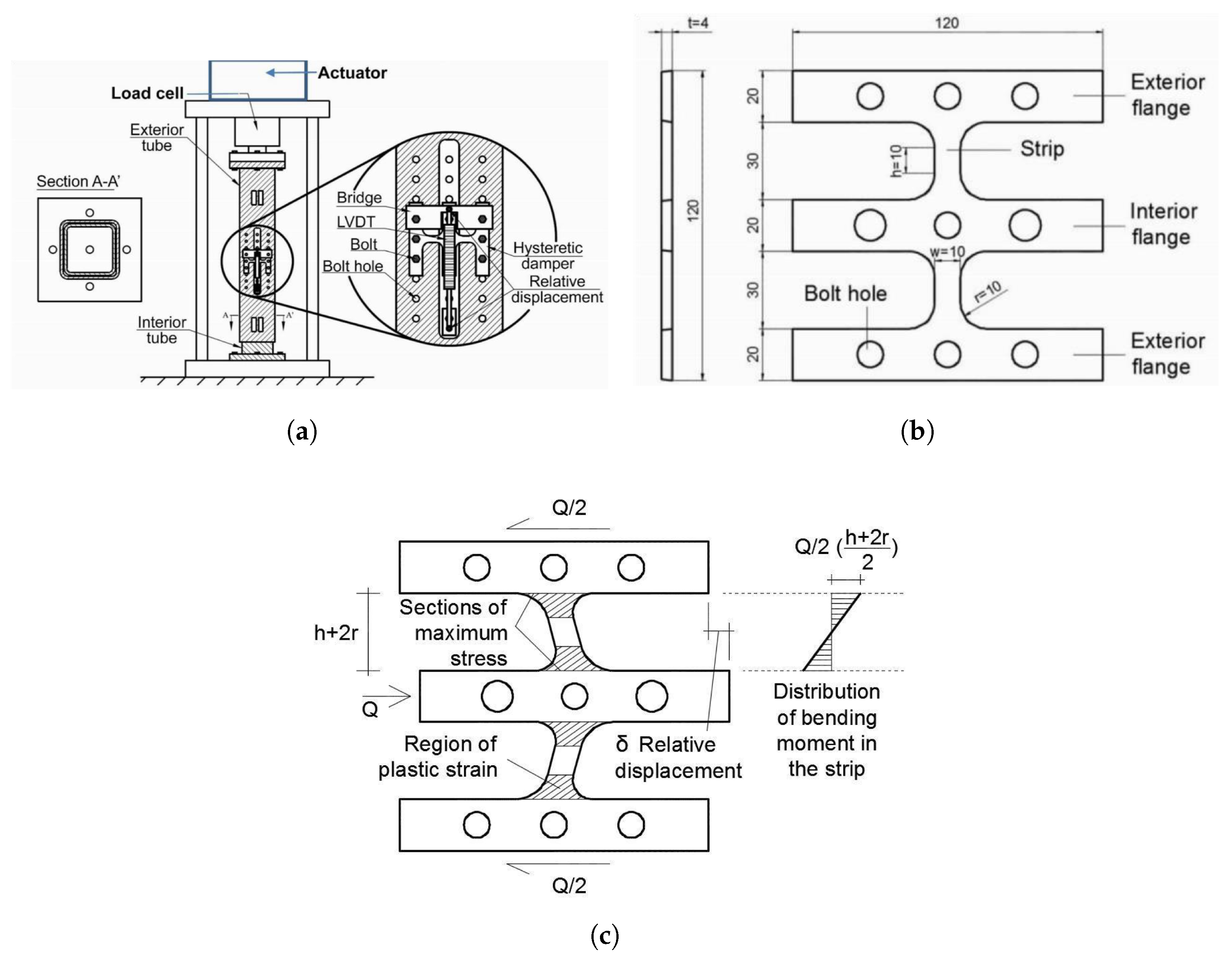
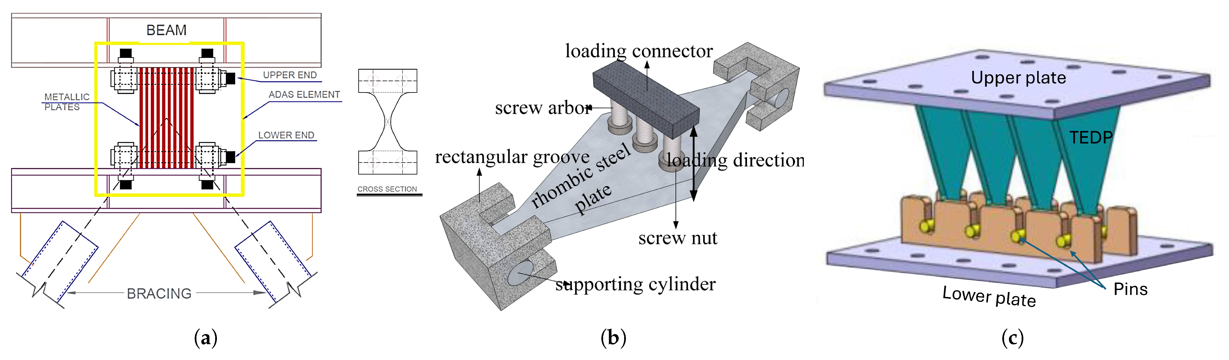
Figure 1 provides an integrated understanding of the relationship between the geometry of the device, the deformation mode, and the energy dissipation mechanism in a hysteretic metal damper. As can be seen, the incorporation of longitudinal slots in the metal plate induces a localized distribution of plasticization zones, favoring the development of stable hysteretic cycles under cyclic loads. The experimental setup shown in subfigure (b) shows how the device is subjected to alternating displacements that generate repetitive curvatures in the weakened sectors, while subfigure (c) reveals the characteristic pattern of cumulative plastic deformation, concentrated in the regions of greatest flexibility. This behavior confirms that the main resistance mechanism is based on a controlled cyclic bending process, where seismic energy is transformed into repeatable plastic deformations, ensuring stable dissipation without a significant loss of initial stiffness. Consequently, this example is particularly illustrative for understanding the design logic followed by other metal dissipators, including those with a “U” geometry, whose efficiency also depends on the location and control of the plastic field.
Although some historical descriptions mention the use of lead in construction elements (e.g., as sheets or support plates), we find no peer-reviewed archaeological or architectural evidence to support the deliberate use of lead layers in the columns of the Alhambra as engineered hysteretic dissipators. Therefore, any such claim would be speculative. However, the beneficial properties of lead is technically relevant (low yield stress, high ductility, and high plastic deformation capacity) have been widely exploited in modern seismic protection systems. Examples include lead cores in elastomeric bearings (lead-rubber bearings) [27], lead extrusion dampers [28], and more recent prestressed lead devices [29], all of which provide stable hysteretic energy dissipation. These engineering applications offer a physically consistent explanation for why lead has been used occasionally to achieve reliable hysteretic behavior in contemporary seismic systems.

2.3. Metallic Hysteretic Dampers: A Dependable Passive Control Technology

Among the various types of passive EDDs, metallic hysteretic dampers are one of the most developed and widely implemented technologies. Also known as yield dampers, their operating principle is simple: they dissipate energy through controlled and repeatable inelastic (plastic) deformation of the metallic components. When a structure is subjected to seismic ground motion, the relative displacements between floors (or between the structure and its foundation) force the dampers to deform. This deformation pushes the damper material beyond its elastic limit and into the plastic range, converting the kinetic energy of the structure into heat, which is then safely dissipated [14,30]. This process is characterized by a force-displacement relationship that forms stable and repeatable loops, known as hysteresis loops. The area enclosed within these loops is a direct measure of the energy dissipated per cycle of movement [31].
Metal hysteretic dampers offer several advantages that have led to their widespread adoption. They exhibit stable and predictable hysteretic behavior, have high energy dissipation capacity, and are constructed from reliable and well-known materials (primarily steel). In addition, their performance is largely independent of loading rate and ambient temperature, and they are relatively inexpensive and easy to manufacture and install, making them an economically viable solution for both new construction and seismic retrofitting of existing buildings [32]. In fact, metal dampers have been used effectively to improve the seismic performance of numerous structures, preventing damage from concentrating on primary elements and limiting it to replaceable dampers [33]. However, despite their proven benefits, these devices are not without challenges: aspects such as low-cycle fatigue, potential residual deformations, and long-term material degradation must be carefully considered in the design.

3. Classification and Working Principles of Metallic Hysteretic Dampers

The diverse family of metallic hysteretic dampers can be systematically categorized according to the primary mechanical action that induces plastic deformation. The three main plastic behavior are dominated by bending, shear, and axial deformation. This classification provides a clear framework for understanding the design, behavior, and application of different types of dampers. The evolution of these designs reveals a clear trend away from simple, monolithic components toward functionally specialized, decoupled systems, where different elements or materials are optimized for specific tasks, such as energy dissipation, stability, and re-centering [34].

3.1. Flexural Yielding Dampers

Flexural dampers dissipate energy through the flexing, both in-plane and out-of-plane, of metal plates or strips. They are among the oldest and most studied types of metal dampers [35].

3.1.1. Added Damping and Stiffness (ADAS) and Triangular ADAS (TADAS) Dampers

Initially developed in the 1980s [36], ADAS dampers typically consist of multiple X-shaped steel plates arranged in parallel [37]. When subjected to lateral displacement, these plates are forced into double-curvature bending, causing widespread yielding throughout the material [38]. TADAS dampers [39] are an improvement on this concept, as they use triangular steel plates instead of X-shaped plates [40]. The conical geometry of the triangular plates is specifically designed to produce uniform bending curvature along their height [41]. This design ensures that plastic stress is distributed almost uniformly throughout the material, avoiding stress concentration and delaying the onset of low-cycle fatigue failure, thereby maximizing energy dissipation capacity before fracture [42]. Both ADAS and TADAS dampers are known for their stable hysteresis behavior and are relatively simple to manufacture and install [2].
The main applications of ADAS/TADAS include bracing systems in steel structures, where they act as ductile fuses. Numerous experimental studies have confirmed their effectiveness in improving seismic performance [43]. However, design challenges remain in preventing out-of-plane instability of slender plates and ensuring reliable connections to the structure. Recent research has explored modular ADAS devices and the use of high-strength bolts or pins to facilitate replacement after severe events. In the case of TADAS, to improve the assembly process, it was proposed to weld a pin to the bottom of the triangular plate and consider slots in the device’s lower support plate. This facilitates assembly, reduces manufacturing costs, provides more stable hysteresis in large deformations, and prevents an abrupt increase in the device’s stiffness [44].

3.1.2. U-Shaped Steel Dampers (USSDs)

U-shaped steel dampers (USSD), first proposed in 1972 by Kelly et al. [15], dissipate energy primarily through bending of their curved and straight steel segments, with shear deformation playing a secondary role. The U-shape allows for large, controlled deformations, making USSDs highly efficient at concentrating plastic deformation in a designated, replaceable element, thus protecting the main structural components [45,46]. USSDs are frequently used in base isolation systems, where they are installed in conjunction with elastomeric bearings to provide additional damping and control large seismic displacements [47]. Modern USSDs designs have incorporated advanced features such as variable thickness and width along the damper [48]. These geometric optimizations aim to distribute plastic deformations more evenly, improve energy dissipation, and optimize overall performance under severe cyclic loads [49]. For example, increasing thickness in regions of high curvature can delay local buckling, and reducing width can help achieve a more uniform deformation demand. Studies have shown that increasing the cross-sectional area in critical regions improves both stiffness and energy dissipation, while strengthening the ends of the U (where it connects to the frame) can prevent irreversible deformations and stress concentrations.

3.1.3. Other Flexural Configurations

Research into flexural dampers continues to generate novel geometries. For example, curved steel dampers have been shown to offer significant improvements in strength, stiffness, and energy dissipation when installed in beam-column connections [50,51]. Studies of shape optimization have shown that the energy dissipation capacity of curved dampers can be improved by more than 30% compared to conventional designs [52]. Tubular dampers, consisting of short segments of steel tubing, offer another simple but effective means of flexural energy dissipation; experiments show that increased tube thickness and width result in higher load capacity and wider hysteresis loop areas [24]. Additionally, dampers with two yield points have been created to efficiently protect the structure from earthquakes of different intensities [53]. These alternative configurations demonstrate the versatility of the flexural yielding mechanism in dampers design.

3.2. Shear Yielding Dampers

Shear yielding dampers use the inelastic shear deformation of steel plates to dissipate energy. These devices are characterized by high initial stiffness and high energy dissipation capacity.

3.2.1. Steel Slit Dampers (SSDs)

Steel slit dampers, also known as metal slit dampers are manufactured from a single steel plate with a series of slots, forming a matrix of vertical steel strips or links [19,54]. When the damper is subjected to lateral displacement, these strips deform primarily through shearing and bending, providing a highly effective mechanism for energy dissipation [55]. SSDs are characterized by their cost-effectiveness, high fatigue resistance, and ability to operate over a wide frequency range [55]. A key failure mode in SSDs is out-of-plane buckling of the steel links, which produces a compressed hysteretic response and reduces energy dissipation [25]. Recent innovations in this field include the development of self-centering disc slot dampers (SC-DSDs), which integrate pre-compressed disc springs to provide a restoring force, thus combining the high energy dissipation of a slot damper with the desirable ability to re-center to minimize residual structural deformation [56]. Previously, the multi-slit damper had been proposed, which combines weak and strong SSDs and a configuration that incorporates protective gaps for its elements, preventing fracture [57].

3.2.2. Steel Shear Panels (SSPs)

Steel shear panels, also known as shear dampers (SD), consist of a solid or perforated steel plate installed within a structural opening, often connected to surrounding beams and columns. Under lateral loading, the panel is designed to yield by shearing across its entire surface. This mechanism provides a very rigid and efficient means of dissipating large amounts of seismic energy, effectively acting as a ductile fuse for the structure [58]. In shear dampers, pinching may occur in the hysteresis curve due to out-of-plane buckling. One way to solve this problem is to use stiffeners [59] or perforated plates with periodic auxetic-shaped cellular forms [60].

3.3. Axial Yielding Dampers

Axial yield dampers are designed to yield stably under tensile and compressive forces, providing symmetrical hysteretic behavior.

Buckling-Restrained Braces (BRBs)

Buckling-restrained braces (BRBs) are a highly advanced and effective type of axial yield damper, widely implemented worldwide [58]. Conventional steel bracing performs excellently in tension, but buckles under much lower loads in compression, resulting in asymmetric hysteretic response with constriction, as well as rapid degradation of strength and stiffness [61]. The BRB overcomes this fundamental limitation through a design that decouples the functions of axial yielding and stability. A BRB consists of a steel core designed to yield under both tension and compression, and a clamping mechanism. This damper usually has a steel jacket filled with concrete or mortar covering it [62]. A release material is applied between the core and the jacket to prevent transfer of axial load to the restraint element, allowing the core to deform axially without friction [61]. The jacket provides continuous lateral support to the core, preventing it from buckling under compression [63]. This allows the steel core to reach its maximum elastic limit in compression, resulting in stable, symmetrical, and complete hysteresis cycles that are virtually identical in tension and compression, which translates into exceptional ductility and energy dissipation capacity [61]. Additionally, the Ribbed Bracing System (RBS) was proposed as a method of preventing buckling. The RBS consists of an internally ribbed tube into which a ribbed shaft is inserted. The sliding of the inner shaft within the tube is facilitated when the diagonal is under compression. Conversely, when the diagonal is under tension, the ribs offer resistance, thereby allowing the bar to deform [64].

3.4. Torsional Yielding Dampers

These devices utilise torsion to generate plastic deformation of the metal and dissipate energy. It has been demonstrated that, under such conditions of stress, it may be feasible to achieve uniform material yielding and equivalent damping coefficients in the approximate range of 0.5 [65]. Furthermore, displacement-dependent post-elastic stiffness can be obtained, thereby enabling dampers installed on different floors to deform more uniformly, thus avoiding a soft story [66]. In order to generate the torsion of the dissipator elements, it is necessary to design a mechanism that transforms lateral loads into torsion [67,68,69].

3.5. Hybrid and Novel Configurations

The evolution of dampers technology shows a clear trend toward combining different mechanisms and materials to overcome the limitations of individual systems and achieve superior, multifunctional performance.

3.5.1. Friction-Metallic Hybrids

Hybrid dampers have been developed that combine friction and metal yield elements in a single device to offer multi-stage performance [70]. For example, a device can be designed where a friction unit, characterized by a stable rectangular hysteresis loop, is activated at small displacements to dissipate energy during minor or moderate earthquakes. If displacements exceed a certain threshold, a metallic yield unit is activated, providing greater resistance, stiffness, and energy dissipation capacity for a large-magnitude earthquake. This synergistic mechanism allows for a structural response that is better adapted to different levels of seismic risk [70].

3.5.2. Self-Centering Metallic Dampers

A major limitation of conventional metal dampers, including BRBs, is their tendency to induce permanent (residual) deformation in the structure after a severe earthquake [62]. This residual drift can leave a building inoperable and costly to repair, even if it has not collapsed. To address this problem, self-centering dampers have been developed, primarily through the incorporation of shape memory alloys (SMAs) [71,72]. These hybrid devices combine the high energy dissipation of steel components with the unique “superelasticity” property of SMAs. The steel elements yield to dissipate energy, while the SMA elements undergo a reversible phase transformation that provides a strong recovery force, returning the structure to its original position and minimizing residual drift [73]. This represents a significant step toward achieving truly resilient structures that can not only survive an earthquake but also quickly return to operation afterward. Table 1 provides a comparative summary of the main characteristics of these types of dampers.
An alternative approach to designing self-centering dissipative devices is the use of preloaded disc springs [74,75] or post-tensioning steel cables [76].

3.6. Proposed Functional Taxonomy for Metallic Dampers

The taxonomy proposed here represents a novel contribution to the field, as it departs from conventional classifications based solely on device geometry. Instead, it introduces a functional perspective that distinguishes the directionality of structural demand, the type of load applied, and the internal dissipation mechanism that triggers yielding. This separation reveals relationships that traditional classifications obscure; for example, cases in which externally applied shear forces are transformed into internal bending moments through the geometry of the device. By enabling a direct connection between device selection and constitutive modeling requirements, this taxonomy provides a more rigorous and mechanistic framework for the design and analysis of metallic dampers.
Table 1. Comparative Overview of Major Metallic Hysteretic Damper Types.
Damper
Type
Primary Yielding
Mechanism
Key Design
Features
Primary
Advantages
Primary
Limitations
TADAS
[40]
Flexural (Bending)Multiple parallel
triangular steel
plates
Simple, cost-effective,
uniform yielding
distribution avoids
stress concentration
Can be susceptible
to out-of-plane
buckling; performance
depends on
connection details
USSD
[46]
Flexural (Bending)
and Shear
U-shaped steel strip,
often with variable
thickness/width
High deformation
capacity, efficient
for base isolation
applications
Can experience
stress concentrations
at curved sections;
potential for complex
failure modes
SSD
[54,77]
Shear and FlexuralSteel plate with
multiple vertical slits
forming deformable
strips
High fatigue
resistance,
cost-effective,
stable hysteretic
behavior
Can exhibit stiffness
degradation;
performance is
sensitive to slit
geometry
BRB
[62]
Axial (Tension
and Compression)
Steel core
decoupled from a
buckling-restraining
casing
Symmetric and
stable hysteretic
loops, high
ductility and
energy dissipation
Can lead to
significant residual
structural drift;
core is not easily
replaceable after
yielding
SMA-Hybrid
[78]
Combined (e.g.,
Flexural + Axial)
Steel components for
energy dissipation
combined with
SMA elements for
recentering
Provides both
high energy
dissipation and
self-centering
capability,
minimizing residual
drift
Higher material
cost, temperature
sensitivity of SMAs,
more complex design
and manufacturing
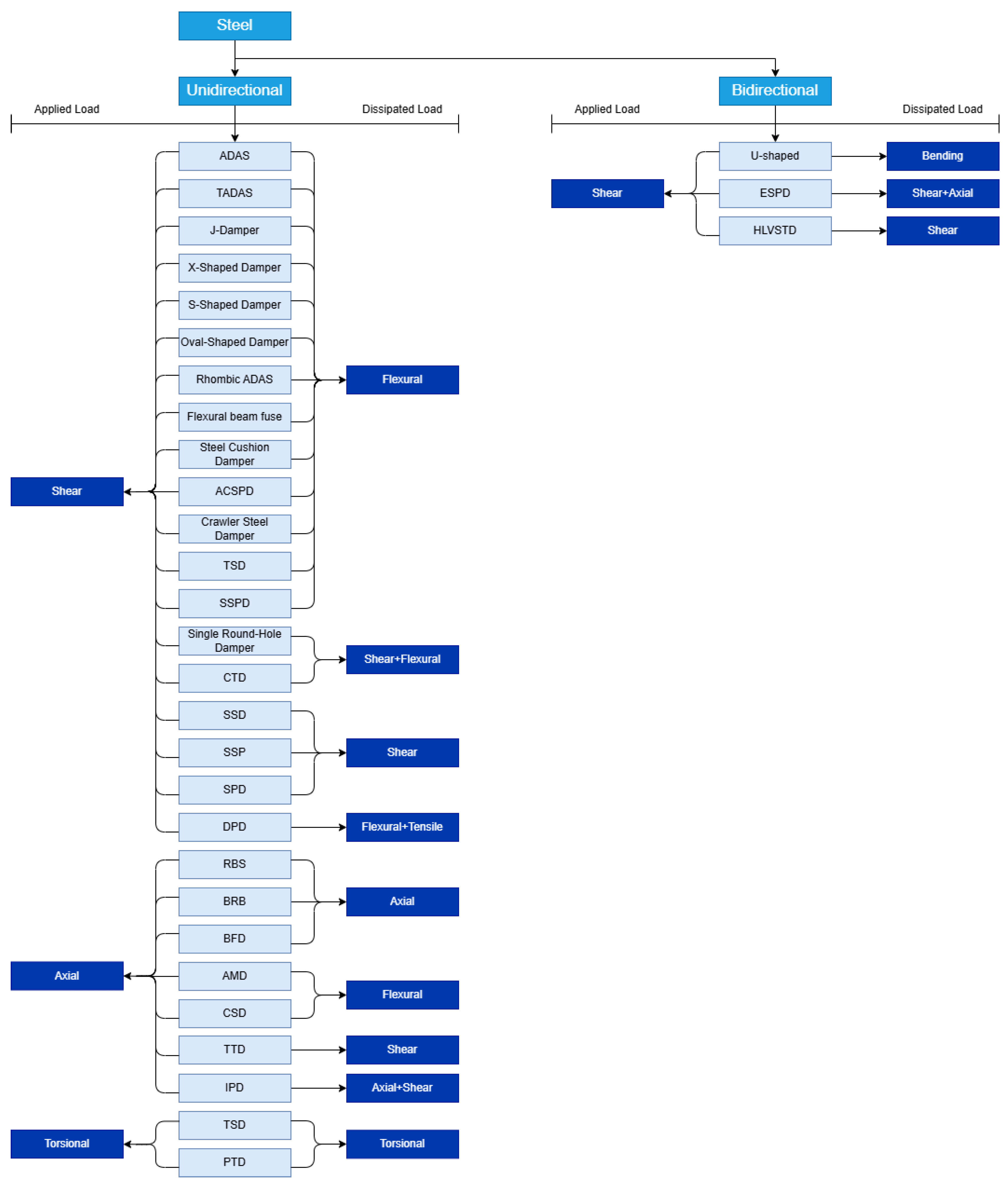
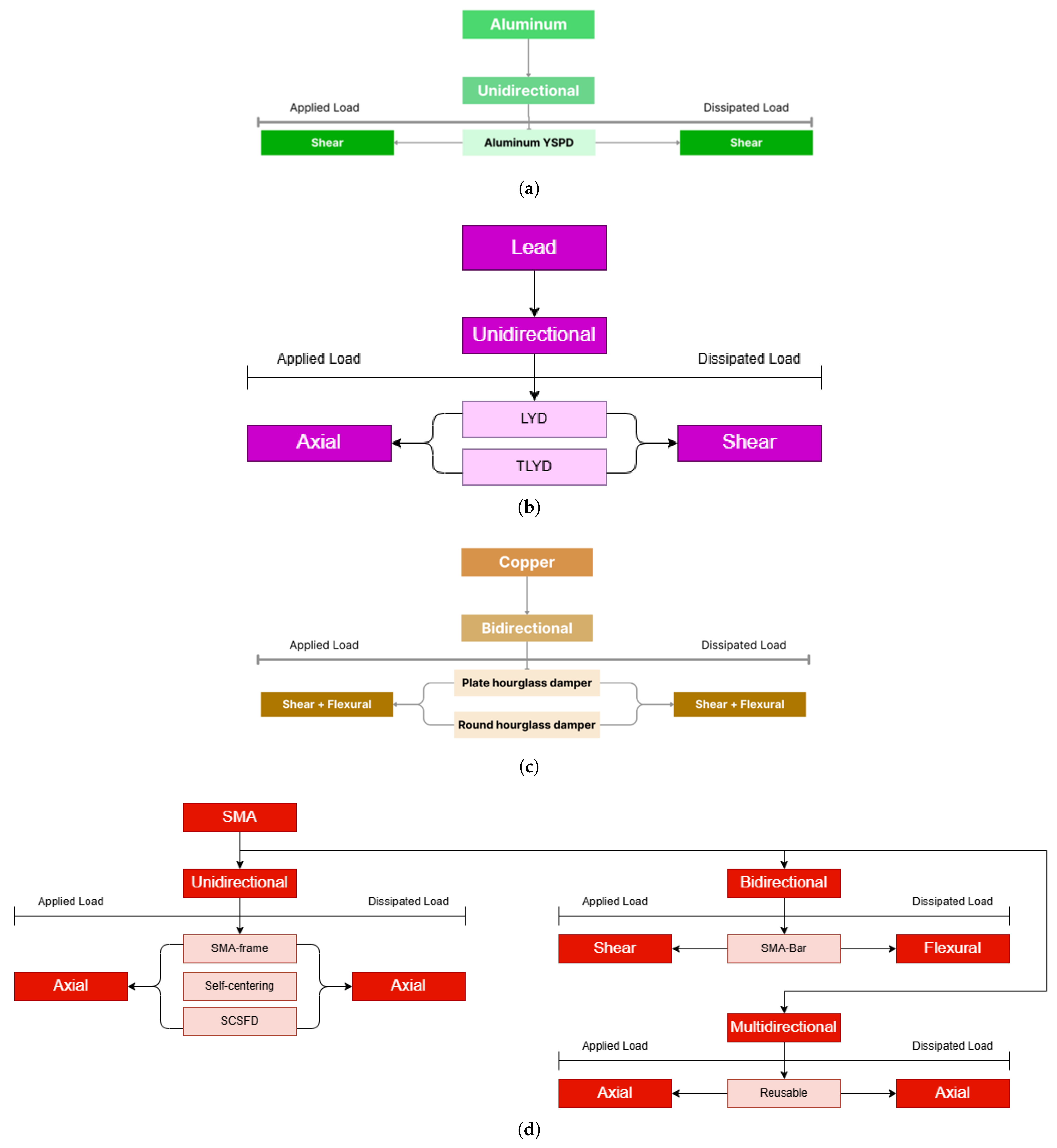
While the previous sections reviewed metallic dampers according to their traditional typologies (e.g., flexural, shear, axial), these classifications are often based on geometry rather than mechanical behavior. To bridge the gap between device selection and performance-based design, we propose a systematic functional taxonomy based on three mechanical vectors: Directionality, Applied Load, and Dissipation Mechanism. Directionality is the term that is used to describe the axes along which a device can deform plastically, thus dissipating seismic energy. Depending on the number of load axes involved in the activation process, dampers can be classified as unidirectional, bidirectional, or multidirectional. A critical innovation of this proposal is the differentiation between the load the device receives from the structure (Applied Load) and the mechanism through which the material yields (Dissipated Load). As illustrated in the taxonomy trees proposed in this section, these vectors are not always coincident. For example, an externally applied shear load can be transformed via device geometry into an internal bending moment (e.g., in ADAS or U-Shaped dampers). Understanding this transformation is vital for selecting the correct computational models, as flexural dissipation involves strain gradients that differ from pure shear yielding Steel remains the predominant material in seismic protection. Figure 2 presents the taxonomy for steel dampers, classifying them into Unidirectional and Bidirectional categories. The classification highlights that “Axial” applied loads—common in bracing systems like BRBs—can be dissipated via distinct mechanisms such as pure axial yielding or controlled buckling. This distinction dictates whether the numerical model requires isotropic hardening (for stable yielding) or complex kinematic hardening (for buckling-induced pinching).
As materials science advances, the taxonomy must extend beyond steel. Figure 3 maps the functional classification for: Aluminum, Lead and Copper, and Shape Memory Alloys (SMA). Prioritized for high ductility and lower yield points, Aluminum is typically utilized in shear-yielding mechanisms to maximize plastic volume. Lead and Copper are distinguished by their rapid recrystallization properties at room temperature, offering high fatigue life under bidirectional loads without significant strain hardening. Finally, Shape Memory Alloys (SMA) category introduces “Self-Centering” as a functional output. The taxonomy reveals that while most SMA devices accept axial loads, they are frequently designed to dissipate energy via flexural deformation of bars to optimize the superelastic flag-shaped hysteresis.
To ground this theoretical classification in practice, Table 2 provides a comprehensive visual compendium of the discussed metallic dampers. This table serves as a visual legend, linking the physical device geometries (e.g., slits, tubes, plates) to the functional categories defined in the new taxonomy.

3.7. General Typologies of Metallic Dampers

The widespread development of hysteretic metal devices has led to a variety of structural configurations designed for stable energy dissipation. The selection of these configurations depends on both the predominant type of stress and the stiffness and ductility requirements of the structural system. Given its historical relevance and widespread adoption, the ADAS family of metallic flexural dampers is presented in Figure 4. These devices, including the classic ADAS, its rhombic variant, and the triangular TADAS configuration, represent the most studied flexure-dominated systems in the literature and are often used as reference geometries to validate new designs, analytical models, and optimisation strategies. Table 2 presents the most representative typologies reported in the literature, grouping devices based on bending, torsional devices, and hybrid solutions that combine multiple deformation modes. This allows for the visualization of each geometry in terms of specific plastic flow patterns. In particular, dampers based on thin plates with controlled curvatures (U-shaped, J-shaped and S-shaped) promote dominant bending mechanisms and have demonstrated stable performance under high-amplitude strain cycles due to the progressive distribution of plastic deformation along the curvature [86,87]. Furthermore, ADAS and TADAS-type devices distribute plastic flow across multiple sections, increasing cumulative dissipation capacity and reducing sensitivity to localized damage concentrations [88,89]. Similarly, X-shaped dampers and derived variants induce shear mechanisms that are efficient for structures with high lateral stiffness, although they exhibit greater sensitivity to vertex strain localization [82].
To systematise the key geometric and mechanical characteristics of flexion-dominated devices, Table 2 presents a comparative summary of the most representative metallic flexion dampers. The table groups slotted, perforated, curved, and hybrid flexion geometries, highlighting the direction of the applied load, the dominant deformation mode, and the functional directionality of each device. Following slotted and perforated plate dampers, Table 3 compiles curved, corrugated, and folded steel geometries. These devices utilise controlled curvature or folding patterns to distribute bending curvature more evenly, increasing ductility and delaying local buckling.
The diversity of bending geometries highlights how flexion-dominated mechanisms can be adapted to balance the demands of ductility, out-of-plane stability, and low-cycle fatigue resistance. However, several widely used devices dissipate energy primarily through shearing rather than bending, which justifies the classification presented in the following section, in Table 4. Additionally, recent developments have explored devices with adaptive topologies and unconventional cross-sections, such as “Steel Cushion” and “Crawler Steel” dampers, which aim to increase cyclic resilience by incorporating progressive deformation paths and geometric reversibility [94,95]. This diversity reflects a shift in design philosophy, from typologies based solely on energy efficiency to configurations focused on durability, cyclic stability, and mitigation of localized damage. In this context, the classification presented serves as a conceptual basis for justifying the detailed focus on U-shaped dampers, discussed in the following section, due to their geometric simplicity, high ductility, and stable hysteretic response.
On the other hand, shear-controlled devices represent a distinct category in which plastic deformation is primarily localised through in-plane shear distortion rather than bending curvature. Table 4 summarises representative configurations, including shear-controlled steel panels, concentric tube systems, pipe-based devices, and emerging laminated core topologies. While metallic shear dampers provide high initial stiffness and high energy dissipation per cycle, many structural applications require devices that respond predominantly to axial forces. This motivates the classification of axial and mixed-mode devices summarised below.
Finally, Table 5 compiles axial and mixed-mode metal dampers, whose main action is governed by tensile-compressive yielding or by coupled mechanisms, such as axial-flexural or axial-viscous interaction. These devices are particularly relevant in braced frames, rocker systems, and structural typologies that require a symmetrical hysteresis response. This classification reveals that axial devices tend to provide highly stable and symmetrical hysteresis loops, especially in buckling-restrained bracing systems. Mixed-mode devices, such as viscoplastic dampers or hybrid configurations, introduce additional functional capabilities, such as self-centring, multi-stage activation, and improved fatigue performance. Their incorporation into performance-based seismic design frameworks requires advanced constitutive models capable of capturing coupled yielding mechanisms.

4. Materials for High-Performance Hysteretic Dampers

The performance, reliability, and failure characteristics of a metallic hysteretic damper are fundamentally determined by the constitutive behavior of its materials. The selection of a material is no longer a simple choice based on passive properties such as ductility, but has become an active design decision to endow the damping system with specific functionalities, such as self-centering.

4.1. Low-Carbon and Low-Yield-Strength (LYS) Steels

The vast majority of metal hysteretic dampers are manufactured from low-carbon or mild steels. These materials are preferred for a number of reasons that make them exceptionally well suited for seismic energy dissipation. Their main advantage is their excellent ductility, which allows them to withstand large repeated plastic deformations without fracturing, an essential requirement for dissipating significant amounts of energy [2]. In addition, they exhibit stable hysteretic behavior, meaning that their force-displacement curves do not degrade significantly after numerous loading cycles. From a practical standpoint, they are also readily available, well known, and relatively inexpensive, making them a cost-effective solution for a wide range of applications [32].
Within this category, low yield strength (LYS) steels have been identified as a particularly advantageous material. LYS steels, such as LYS100, have an even lower yield strength and greater elongation capacity than conventional mild steels [32]. Research has shown that some grades of LYS exhibit “superplastic” behavior when subjected to shear deformation, achieving maximum shear deformations an order of magnitude greater than their maximum tensile deformations [33]. This exceptional plastic deformation capacity translates directly into a very high energy dissipation capacity per unit mass. As a result, LYS is considered an optimal material for the manufacture of lightweight and compact dampers, since a smaller amount of material can dissipate the same amount of energy compared to ordinary carbon steel or even lighter metals such as aluminum, whose energy dissipation per unit mass is significantly lower [33].

4.2. Lead Extrusion Damper (LED)

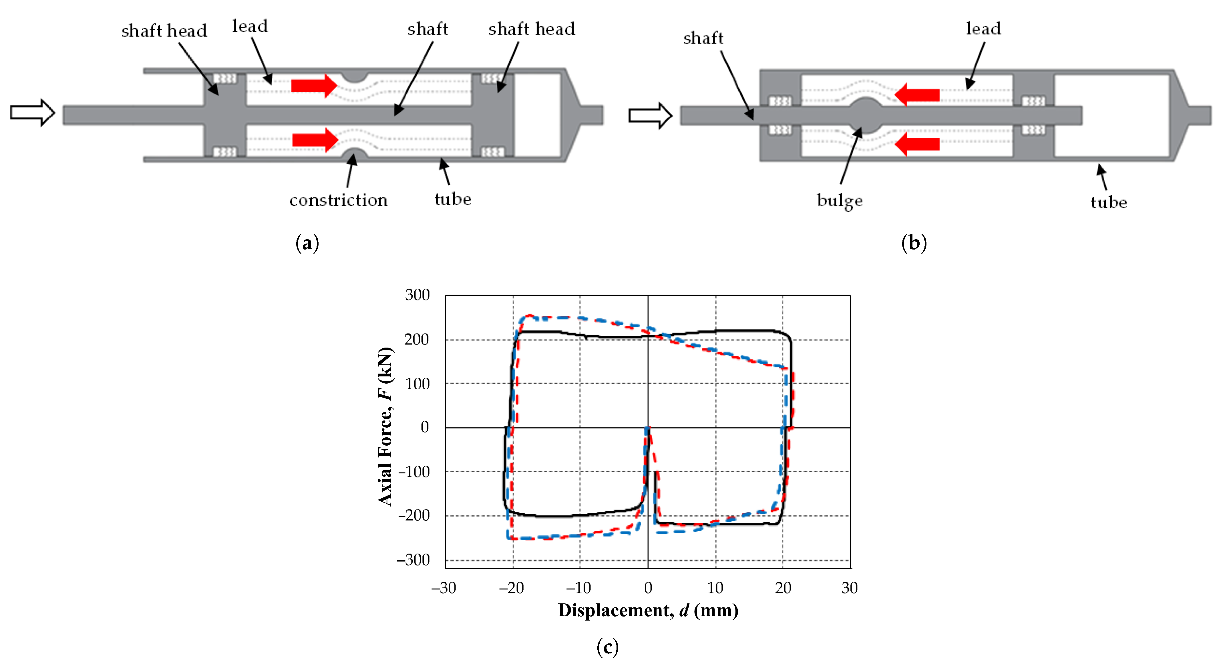
In the context of lead extrusion dampers, plastic deformations are induced by the metal extrusion process. Dampers that utilize this material exhibit stable hysteresis curves due to the material’s low yield stress, high plastic deformation capacity, flexibility, and ductility [106,107]. Lead recrystallizes at room temperature and recovers its mechanical properties [2], so it does not require replacement or repair after an earthquake [108]. The Lead Yielding Damper (LYD) comprises two cylinders, one inner and one outer, with lead rings connected in parallel to each other. These rings deform due to the relative displacement between the cylinders. The device exhibited notable resistance to low-cycle, large-displacement fatigue [109]. The Telescopic Lead Yielding Damper (TLYD) is obtained by connecting several LYDs in series, resulting in the presence of multiple yield points [109]. Figure 5 shows the fundamental configurations and mechanical behavior of lead extrusion dampers. The two structural arrangements commonly reported in the literature are shown in Figure 5a,b: the constrained tube design, in which lead is forced through a narrow section of the steel cylinder, and the bulged shaft configuration, where extrusion occurs through the annular space generated by the widened portion of the central shaft. Despite their geometric differences, both devices rely on the plastic deformation of lead to dissipate seismic energy, producing the stable, nearly rectangular hysteresis response characteristic of LEDs, as shown in Figure 5c.
Lead extrusion dampers dissipate seismic energy through plastic deformation and extrusion of lead, which is forced through a constriction in a cylindrical tube [110] or through the annular space formed by a bulging shaft [111]. In both configurations, only the lead undergoes plastic deformation, while the remaining components remain elastic, resulting in negligible low-cycle fatigue and stable energy dissipation capacity. The hysteresis response of these devices is typically rectangular, similar to that of Coulomb/friction dampers, with efficiency coefficients ranging from 0.73 to 0.79 for bulged tube designs and from 0.90 to 0.93 for bulged shaft devices [112]. Early developments by Robinson and Greenbank established the fundamental geometries and demonstrated that the bulged shaft configuration offers better manufacturability, more stable hysteresis, and broader applicability in structural control [110,111].

4.3. Advanced Alloys for Enhanced Functionality

While LYS steels are excellent for pure energy dissipation, the quest for better performance and new functionalities has led researchers to explore more advanced alloys.

4.3.1. Stainless Steels

Stainless steel has been proposed as an alternative to mild steel for high-performance dampers. The main advantage of stainless steel lies in its inherently superior ductility and strain hardening characteristics, which can translate into significantly higher energy dissipation capacity before failure compared to mild steel [34]. A study of a stainless steel concentric tube damper revealed that its cumulative ductility was approximately four times greater than that of similar dampers made from mild steel. Furthermore, the inherent corrosion resistance of stainless steel represents an important practical advantage [34]. It ensures long-term durability and reliability over the extended service life of a structure, reducing maintenance requirements and mitigating the risk of performance degradation due to environmental exposure [34].

4.3.2. Shape Memory Alloys (SMAs)

Shape memory alloys (SMAs) represent a class of “smart” materials that have introduced a new transformative function in seismic dampers: self-centering [113]. The most common SMA used in these applications is a nickel-titanium alloy (Nitinol or NiTi). SMAs possess two unique thermomechanical properties: the shape memory effect and superelasticity [113]. When a superelastic SMA is deformed beyond its apparent elastic limit, it does not undergo permanent plastic deformation. Instead, it undergoes a reversible, stress-induced phase transformation from its austenite crystal structure to its martensite structure. Upon unloading, the material transforms back into austenite and recovers its original shape, even after undergoing large deformations (up to 4–8%) for NiTi [113].
This behavior produces a characteristic flag-shaped hysteresis loop, which provides both energy dissipation (the area of the loop) and a strong recovery force. In hybrid dampers, shape memory alloy (SMA) elements are combined with conventional steel elements [114]. Steel provides most of the energy dissipation through its large, stable hysteresis loops, while superelastic SMA provides the restoring force necessary to return the structure to its initial position, effectively eliminating the residual drift that affects conventional systems [71]. This active control over the state of the structure after an earthquake represents a significant evolution from simple energy dissipation to active recovery management. However, the widespread adoption of SMAs is currently limited by challenges such as their higher cost and temperature sensitivity [113].
In addition to hybrid steel-SMA systems, various devices based exclusively on shape memory alloys have been developed in the literature, which can be classified according to the direction of the applied load and the type of response obtained. In the unidirectional category, SMA-Frame devices [115] incorporate superelastic bars or cables that work predominantly under axial tension, providing effective recentring capacity and dissipative frames. The Self-Centering (CF) [116] and Self-Centering Slip Friction Dampers (SCSFD) systems [117] belong to this same family, employing axial SMA configurations to generate restoring forces without resorting to residual plastic deformation. On the other hand, bidirectional systems are based on SMA-Bar type elements [118], which can dissipate energy in both shear and bending regimes, allowing their integration into connections subjected to multiaxial demands, such as beam-column joints or bridge nodes. Finally, multidirectional devices such as reusable SMA-based systems employ axial configurations that can be activated repeatedly without significant loss of efficiency, providing a stable and fully recoverable energy dissipation mechanism [119,120]. This classification highlights that SMA-based technology not only offers effective re-centring capability but also a high degree of functional versatility, enabling the design of systems with axial, flexural, shear, or combined responses tailored to specific structural requirements.

5. Advanced Computational Modeling of Damper Behavior

Another additional contribution of this manuscript is the integration of advanced constitutive modeling techniques in the context of metal damper design. While previous reviews have generally addressed material models in isolation, the present work consolidates nonlinear kinematic hardening, ductile fracture formulations such as the GTN model, and recent phase field approaches into a unified framework. This combined perspective highlights how specific dissipation mechanisms (dominated by bending, shearing, or mixed) interact with microstructural damage processes and cyclic hardening rules. By articulating these connections, the manuscript provides a novel, physics-based foundation for the numerical simulation of damper behavior, going beyond purely phenomenological descriptions.
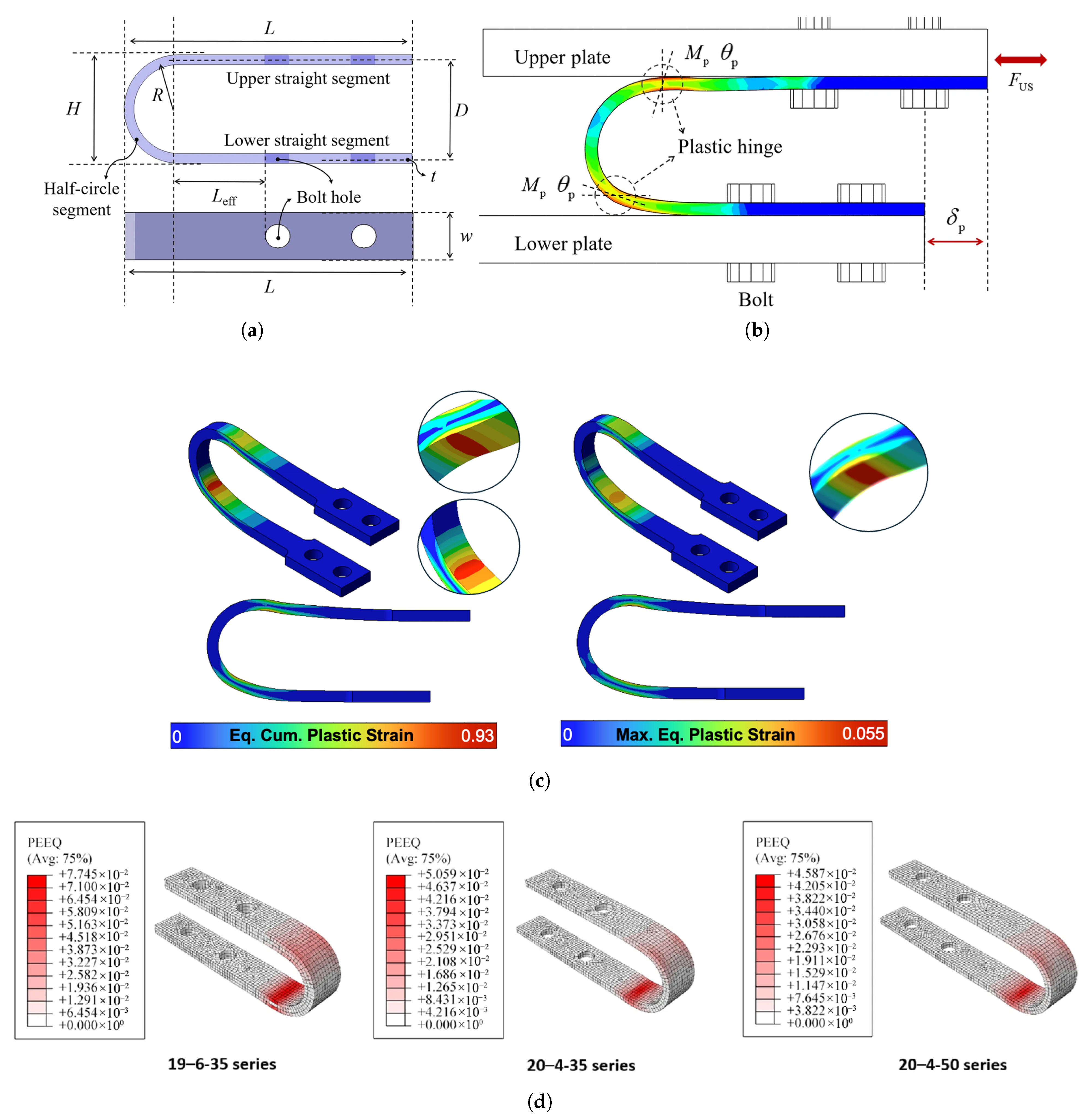
Figure 6 illustrates the direct relationship between the geometry of the U-shaped damper and the associated hysteretic dissipation mode. First, subfigure (a) shows the basic geometric configuration, whose main parameters are the web width W, thickness t, and radius of curvature R, which govern the stress state and strain distribution during the cyclic response. In (b), the equivalent plastic strain contours obtained through finite element analysis reveal that configurations with low R / t ratios tend to promote more uniform plasticity along the curvature, while higher ratios lead to a marked localization of strain in a reduced region of the arc. This phenomenon implies a transition from a distributed dissipation mechanism to behaviors where damage accumulates locally, reducing usable ductility. Subfigure (c) shows the spatial distribution of cumulative and maximum equivalent plastic strain, illustrating the effect of the geometric ratio R / t on the extent and localization of plastic deformation. According to recent experimental studies, configurations that concentrate plasticity at a critical point tend to exhibit a more accelerated degradation of stiffness and strength under prolonged cyclic loading, compromising their service life in severe seismic scenarios [121,122]. In contrast, designs that favor distributed plasticization exhibit more stable behavior and greater cumulative dissipation capacity, justifying the importance of a geometric selection oriented toward the desired deformation mechanism and not solely toward achieving initial strength.
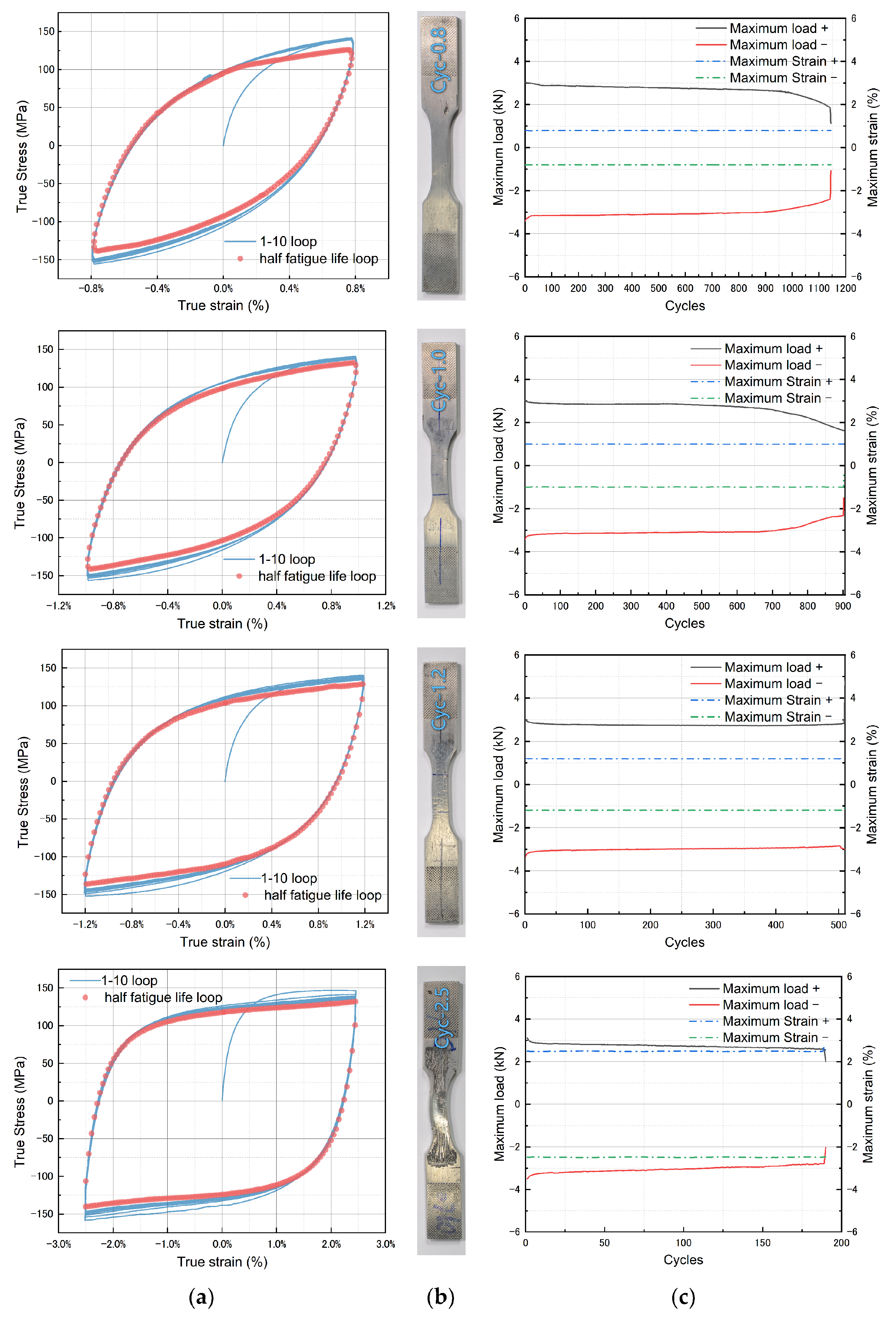
Figure 7 provides an integrated illustration of the cyclic behavior, damage accumulation, and fatigue life of a Zn–22Al alloy used as a material for seismic dampers. Subfigure (a) shows the stress–strain curves under different load amplitudes, where it is possible to identify initial cyclic hardening followed by hysteretic stabilization, a phenomenon typical of materials subjected to repetitive plastic deformation and associated with the mobility and reorganization of dislocations. Subfigure (b) shows a visual comparison between the specimens before and after the tests, highlighting the location of plastic damage and the onset of microcracks associated with deformation concentrations. Finally, subfigure (c) shows the progressive reduction in maximum load with the number of cycles, characteristic of low cycle fatigue (LCF), where stable energy dissipation occurs at the expense of internal damage accumulation.
The design and optimization of modern metallic hysteretic dampers rely heavily on advanced computational modeling. While simple bilinear or elastoplastic models can provide a first-order approximation of damper behavior, they are insufficient for predicting the complex phenomena that govern damper performance under severe and irregular seismic loads, such as low-cycle fatigue and ductile fracture. Progress in modeling reflects a significant shift from empirical and phenomenological adjustment of macroscopic behavior to sophisticated, physics-based prediction of the underlying mechanics of the material. This evolution has been made possible by the development of advanced constitutive models that capture the intricate details of cyclic plasticity and micromechanical damage.
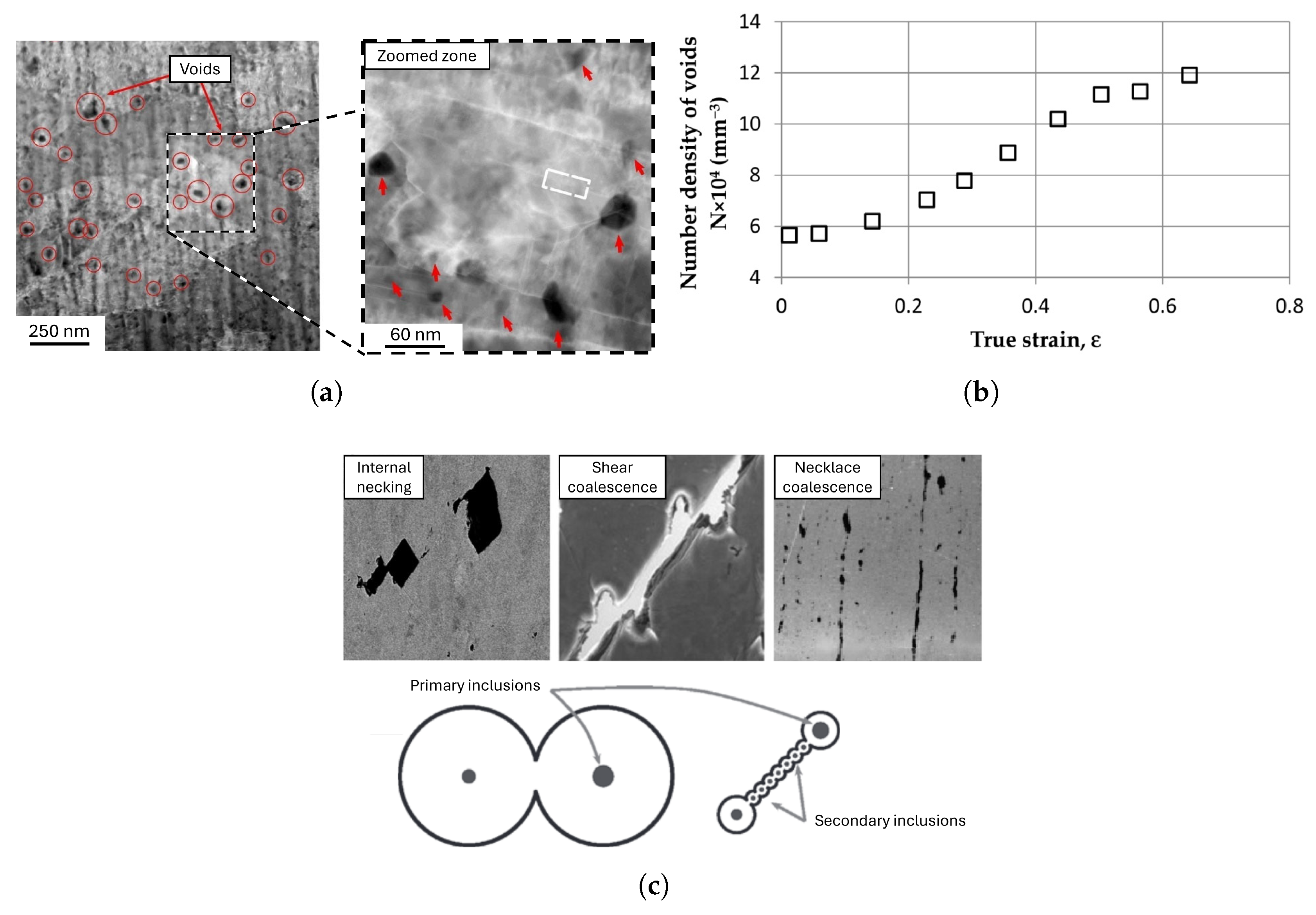
Figure 8 summarizes the characteristic microstructural sequence of ductile damage in steels subjected to cyclic loads, which is essential for understanding the stability or degradation of hysteretic behavior in metal dampers. Subfigure (a) shows the nucleation of voids in the metal matrix, generally associated with plastic incompatibility around inclusions or grain boundaries. As the cumulative plastic deformation increases, these voids undergo progressive growth and greater density, as shown in (b), which induces a localized reduction in the effective resistant section. Finally, the coalescence and grouping of voids, shown in (c), leads to the localization of damage and, eventually, to the ductile collapse of the material. This behavior has been extensively described in classic ductile fracture studies based on the nucleation–growth–coalescence theory, such as the work of Tvergaard and Needleman (1984) [124] on bars under tension, and the microstructural analysis of Bay and Wierzbicki (2008) [125] on the formation and evolution of cavities in steels. In the context of computational modeling of dissipators, these mechanisms are decisive, as they condition the selection of advanced constitutive models—such as those based on the Gurson-Tvergaard-Needleman criterion—used to reproduce the inelastic cyclic response and stable energy dissipation.

5.1. Damage Localization and Fracture Evolution in Metallic Dampers

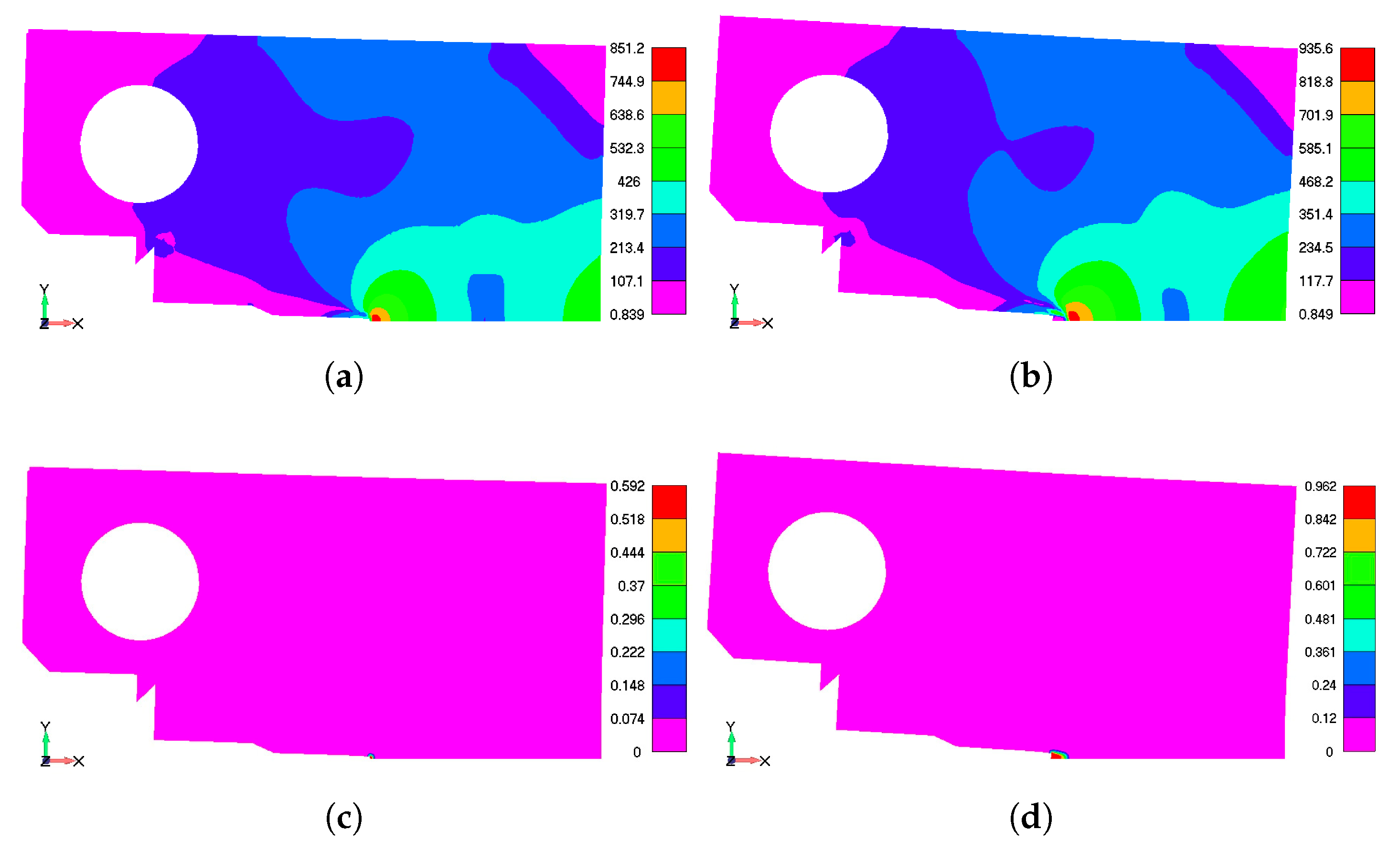
Figure 9 summarizes the ability of phase-field formulations to continuously represent, without explicit failure criteria, the progression from the initial elastic response to damage localization and the eventual propagation of a ductile crack in AISI 316L steel. In a intermediate stage (Figure 9a,c), the equivalent stress field shows a a narrow band of high stresses, coinciding with onset of damage; and in the final state (Figure 9b,d), the crack is fully developed, demonstrating the coalescence of damaged zones and the loss of continuity. This sequential behavior—initiation, growth, and coalescence of damage—is precisely the phenomenon that phase-field formulations allow to be reproduced with high numerical fidelity.
From a methodological standpoint, phase-field models incorporate a diffuse damage parameter that couples its evolution with the local plastic response, avoiding ad-hoc criteria for fracture initiation. Recent advances have allowed this formulation to be extended to fatigue problems and low-frequency cyclic loading through adaptive refinement strategies and accelerated simulation schemes [128,129]. For the design of metallic dampers, this contribution is key: phase-field analysis allows the identification of the preferential fracture path, which can be used to adjust geometries, thicknesses, and radii of curvature in hysteretic devices and prevent premature brittle failure. Coupled plasticity-fracture damage models for structures subjected to large deformations [130,131] have been successfully applied and can be extended to metallic dampers. For phase-field simulations, high mesh resolution and precise parameter calibration are required, which increases computational and experimental costs [132].

5.2. Fundamentals of Cyclic Plasticity

When a metal is subjected to cyclic loads that induce plastic deformation, its behavior differs fundamentally from its response under monotonic loading. To accurately model this behavior, it is necessary to understand two key phenomena.

5.2.1. Isotropic vs. Kinematic Hardening

Hardening describes how the yield surface of a material—the boundary between elastic and plastic behavior in stress space—evolves with plastic deformation. The two main models are isotropic and kinematic hardening. Isotropic hardening assumes that, as the material deforms plastically, the yield surface expands uniformly in all directions without changing its center [37]. This correctly predicts that, after tensile yielding, the material will have a higher stress resistance under subsequent tensile loading (strain hardening). However, it incorrectly predicts that the strength resistance under compression will also increase by the same amount. This model is suitable for monotonic or pulsating loads (e.g., tension-zero stress-tension), but fails to describe behavior under reverse loading [37]. In contrast, kinematic hardening assumes that the yield surface moves in stress space without changing its size or shape. This translation is governed by the evolution of an internal stress tensor, often referred to as residual stress. Kinematic hardening is essential for modeling materials under cyclic loading because it can capture the Bauschinger effect [37].

5.2.2. The Bauschinger Effect

First observed by Johann Bauschinger in the 19th century, the Bauschinger effect is a critical phenomenon in cyclic plasticity. It describes the reduction in a material’s yield resistance when the direction of loading is reversed [133]. For example, if a steel specimen is subjected to tension beyond its elastic limit and then to compression, it will begin to flow under compression at a stress magnitude significantly lower than its initial tensile elastic limit [134]. This effect is attributed to the development of internal residual stresses and dislocation structures during the initial plastic deformation. The accumulation of dislocations at barriers such as grain boundaries creates local residual stresses that oppose the initial applied stress but facilitate the movement of dislocations in the opposite direction, effectively reducing the elastic limit when the load is reversed. In hysteretic dampers, which undergo repeated cycles of tension and compression, the Bauschinger effect is the dominant phenomenon shaping the hysteresis loops. Therefore, any accurate predictive model must incorporate a kinematic hardening rule to capture this behavior [2].

5.3. Non-Linear Kinematic Hardening: The Chaboche Model

While a simple linear kinematic hardening rule can capture the Bauschinger effect, the actual cyclic response of metals is more complex, often involving cyclic hardening (an increase in stress amplitude at constant strain) or cyclic softening (a decrease in stress amplitude), as well as progressive plastic strain accumulation (a progressive accumulation of plastic strain under stress-controlled cycles with a nonzero mean stress).The Chaboche model is a sophisticated nonlinear kinematic hardening formulation that has become a state-of-the-art tool for accurately simulating cyclic plasticity effects such as ratcheting and mean-stress relaxation [135].
The model, an extension of the Armstrong–Frederick rule, achieves its accuracy by decomposing the kinematic backstress tensor into multiple components [135]. Each backstress component evolves according to its own nonlinear rule, generally with a dynamic recovery term that limits its growth. The superposition of several backstress components, each saturating at a different rate, allows the model to capture with high fidelity the transient cyclic hardening behavior and the shape of the stabilized hysteresis loop [2]. For proportional uniaxial loading, the resulting backstress can be written as a function of the equivalent plastic strain as shown in Equation (1):
α ( ε pl ) = k = 1 n 2 3 C k γ k 1 e γ k ε pl
where α is the backstress, ε pl is the equivalent plastic strain, and n is the number of backstress components. The parameters C k and γ k are, respectively, the kinematic hardening modulus and the dynamic recovery parameter, which control the initial hardening rate and the saturation rate of each backstress component. The quantity ( 2 / 3 ) C k / γ k corresponds to the saturated value of the total backstress under proportional uniaxial loading, i.e., the maximum translation of the yield surface predicted by the kinematic hardening model [2,19]. Numerous studies have shown that the Chaboche model, often combined with an isotropic hardening component to account for global cyclic hardening or softening, provides excellent correlation with experimental results for steel hysteretic dampers, particularly for large accumulated plastic deformations where simpler models fail [22].
The main challenge in its application is the calibration of its numerous material parameters (e.g., and for multiple residual stress components). These parameters cannot be determined directly from a simple tensile test and generally require an inverse analysis or optimization procedure, where the parameters are adjusted iteratively until the model output provides the best fit to a set of experimental cyclic test data [136,137]. The primary challenge in applying the Chaboche model lies in the calibration of its numerous material parameters (e.g., C k and γ k for multiple backstress components). These parameters cannot be determined directly from a simple monotonic tensile test and typically require an inverse analysis or optimization procedure. In this process, parameters are iteratively adjusted until the model output provides the best fit to a set of experimental cyclic test data [135,138]. This intensive calibration requirement is a significant barrier to its use in routine engineering design, as discussed further in Section 7.3.

5.4. Micromechanical Damage Modeling: The Gurson-Tvergaard-Needleman (GTN) Model

While the Chaboche model stands out for its ability to predict the stress-strain response of a damper, it does not intrinsically predict when the material will fail. Ductile fracture in metals is a process of material degradation at the microstructural level, driven by the nucleation, growth, and coalescence of microscopic pores [139]. The Gurson-Tvergaard-Needleman (GTN) model is a powerful physics-based constitutive model designed to simulate this entire process, enabling the prediction of ductile fracture initiation. The GTN model is a coupled damage model, which means that damage evolution is directly incorporated into the material constitutive equations [46]. The model describes the three stages of ductile fracture. The first stage is pore nucleation, where new pores form as a function of plastic deformation, which is generally assumed to follow a normal distribution around a mean nucleation strain [140]. The second stage is pore growth, where existing pores grow as the material deforms plastically. The growth rate is very sensitive to stress triaxiality (the ratio of hydrostatic stress to equivalent stress), such that high triaxiality (tensile states) favors rapid volumetric growth [141]. The final stage is pore coalescence. When the void volume fraction reaches a critical value, the inter-void ligaments begin to narrow and fail, causing rapid coalescence of the voids and the formation of a macroscopic crack.
The GTN model has been successfully used to predict ductile fracture in a wide range of structural steels [42,142]. However, like the Chaboche model, its predictive accuracy depends on the proper calibration of its parameters (initial porosity, nucleation porosity, critical porosity, failure porosity, etc.), which often requires a combination of detailed microstructural analysis and a series of mechanical tests on notched specimens designed to create different triaxial stress states [143].
It is crucial to note that for high-fidelity fracture simulations, plasticity models (like Chaboche) and damage models (like GTN) must be fully coupled. In a coupled model, plastic strain drives damage growth (void growth), and accumulated damage in turn degrades the material response (e.g., softening the yield surface) [144]. This bidirectional coupling captures the true physics but introduces significant computational complexity and numerical stability challenges, contributing to the modeling hurdles discussed in Section 7.3.

6. Influence of Manufacturing on Damper Performance

The transition from a computational design to a high-performance physical damper critically depends on the manufacturing process. The chosen manufacturing method not only determines the economic viability of the damper, but also confers characteristics, such as residual stresses, microstructural alterations, and geometric accuracy, that significantly influence its mechanical behavior, fatigue life, and overall reliability. The rise of additive manufacturing is beginning to challenge the traditional limitations of manufacturing, heralding a shift from “design for manufacturing” to “manufacturing for design. [12]”.

6.1. Conventional Manufacturing Techniques

Conventional manufacturing of hysteretic dampers typically involves a combination of processes such as cutting, forming, machining, and welding. While these methods are effective and cost-efficient for mass production, they can introduce characteristics that impair damper performance. For example, welding is commonly used to assemble dissipator components, but intense localized heating and subsequent cooling create a heat-affected zone (HAZ) where the microstructure and mechanical properties of the material can be significantly altered, potentially creating a weak point. Welding also introduces significant residual tensile stresses, which can accelerate the onset of fatigue cracks and reduce the service life of the damper [145]. Similarly, processes such as flame cutting or rough machining can create surface imperfections such as nicks and scratches. These geometric discontinuities act as stress concentrators, becoming preferred locations for fatigue cracks under cyclic loading, which can lead to premature failure [146]. The design of connections may also be constrained by manufacturing limitations. For example, to avoid increased springback force at large displacements in some slot-type dampers, the use of pin connections and slotted holes is required, which can significantly increase production costs compared to simpler rigid connections [147]. These factors highlight that, in conventional manufacturing, the optimal design is often a compromise between ideal performance and the practical limitations and inherent imperfections of the manufacturing process.

6.2. Emerging Trends: Additive Manufacturing (AM)

Additive manufacturing, or 3D printing, is a technology that builds components layer by layer directly from a digital model, usually by melting metal powder with a laser or electron beam (e.g., powder bed fusion, PBF) [148]. This technology fundamentally alters the relationship between design and manufacturing. Instead of being limited by what can be cut, bent, or welded in practice, additive manufacturing offers almost unlimited geometric freedom [12]. This capability is particularly useful for dampers design. It enables the use of topological optimization algorithms, which can determine the most efficient distribution of material to achieve specific performance goals (e.g., maximizing energy dissipation for a given weight). The result of this process is frequently highly complex geometries that are optimally suited to their function but would be difficult to manufacture using conventional methods. This makes additive manufacturing a favorable option [149]. Additive manufacturing enables the production of a new class of algorithmically designed dampers with superior performance-to-weight ratios and precisely controlled hysteretic behavior.
Despite its potential, the application of metal additive manufacturing in seismic dampers is still in its early stages and faces several challenges that are the subject of active research [12,150]. These challenges include porosity [151], where incomplete fusion between powder particles can leave microscopic pores within the material that act as crack initiation points and reduce ductility and fatigue life [152]. Another issue is anisotropy, as the layer-by-layer build process can generate direction-dependent mechanical properties that must be considered in the design. The rapid heating and cooling cycles inherent in additive manufacturing can also generate high levels of internal residual stress, which may require post-processing heat treatments. Finally, cost and scale remain factors to consider; currently, metal additive manufacturing is more expensive and slower than conventional manufacturing for large, simple components, although it can be cost-competitive for highly complex, low-volume parts [153]. As these challenges are overcome, additive manufacturing is poised to become a key technology for the next generation of ultra-high-performance seismic dampers.

7. Identified Challenges and Future Research Directions

Despite significant advances, the field of metallic hysteretic dampers continues to face numerous critical challenges in the areas of design, functionality, and modeling. These challenges are interconnected by a central theme: the uncertainty gap between the idealized conditions assumed in design and the complex and variable reality of seismic loads, long-term environmental exposure, and the inherent behavior of materials. Bridging this gap is the primary driver for future research and innovation.
Finally, a significant barrier to the widespread commercial adoption of advanced dampers is the lack of standardized metrics for comparative efficiency. While current literature extensively characterizes the mechanical behavior of individual devices, there is no unified framework to evaluate dissipation efficiency relative to material consumption (e.g., cumulative energy dissipated per unit weight of steel) or manufacturing complexity. A rigorous comparative analysis is currently hindered by the heterogeneity of experimental protocols, such as varying displacement histories, scale factors, and loading rates, employed across different studies. This lack of standardization makes it difficult for practitioners to assess the cost-benefit ratio of different topologies objectively. Therefore, a critical direction for future research is the establishment of normalized performance indices that account for the weight of the active metallic material. Such metrics would allow for a direct evaluation of material efficiency and modularity, guiding the industry toward designs that maximize energy dissipation while minimizing resource consumption and fabrication costs.

7.1. Challenges in Damper Design and Optimization

The main design challenges lie in accurately predicting low cycle fatigue (LCF) life. The primary failure mode of a well-designed hysteretic damper is LCF, which consists of damage accumulation under a small number of cycles of large plastic strain [154]. Actual seismic events impose highly irregular and variable amplitude load histories. Predicting this failure requires the physics-based damage models discussed in Section 5.4, which must account for defects introduced during manufacturing (Section 6). Traditional methods are often inadequate for ultra-low cycle fatigue, where failure occurs in less than ten cycles [154,155]. A critical area for future research is the development of more sophisticated LCF models that can accurately account for the effects of load sequence and multiaxial stress states. Another important challenge is addressing self-centering and residual drift. A significant disadvantage of conventional high-performance dampers, such as BRBs, is the residual drift they can leave in a structure after an earthquake [62]. While solutions using shape memory alloys (SMAs), as introduced in Section 4.3.2, have proven effective, their high cost remains a barrier [113]. Therefore, developing novel, cost-effective, and reliable self-centering systems is a key design goal. This could involve new hybrid designs or innovative mechanical systems that provide recovery force without compromising energy dissipation [73]. Finally, the field must move toward multi-risk design. Structures are often exposed to multiple types of extreme loads, but hysteretic dampers are designed almost exclusively for seismic loads. Their behavior under wind-induced vibrations, which involve a very high number of low-amplitude cycles, is not fully understood and can lead to long-cycle fatigue problems [156]. Future research should develop dampers and design strategies that provide robust protection against a variety of potential threats.

7.2. Challenges in Functionality and Long-Term Performance

The main challenges in terms of functionality relate to durability and long-term performance. Metal dampers are expected to remain inactive but fully functional throughout the entire service life of a building, which can exceed 50 years. During this period, they are exposed to environmental factors that can cause corrosion and material aging. The long-term deterioration of damper properties and its effect on seismic performance is a critical but under-researched area, requiring more comprehensive studies on material performance and protective coatings [73]. Another functional challenge is post-earthquake evaluation and replacement. Efficient and reliable non-destructive evaluation techniques are needed to assess the remaining capacity of dampers and determine whether they need to be replaced. In addition, dampers must be designed for easy and economical replacement, which has implications for their connection details and integration with the surrounding structure [58]. Research on integrated structural health monitoring systems and modular “design for replacement” concepts is a crucial avenue for improving post-earthquake recovery.

7.3. Challenges in Predictive Modeling and Simulation

In predictive modeling, one of the main obstacles is the calibration of advanced material models. The superior predictive capability of advanced constitutive models such as Chaboche and GTN comes with greater complexity, as they contain numerous parameters that must be calibrated through extensive and costly experimental testing programs [52]. This complexity limits their use in routine design practice, making the development of more agile and cost-effective calibration procedures a major challenge [138]. Another challenge is the need for robust models that can fully couple the physics of plasticity and damage accumulation. In reality, these processes are not independent: damage softens the material and affects its plastic response, while plastic deformation causes damage [2]. Developing and validating computationally stable models that fully couple these effects is essential for accurately predicting the ultimate failure of dampers. Finally, the computational efficiency required to make these powerful simulation tools practical for iterative design remains an ongoing challenge. Performing nonlinear analyses of the temporal evolution of a full-scale structure with these sophisticated models is extremely computationally expensive, which can be prohibitive for design studies that require numerous iterative analyses [157]. Future research is needed in areas such as model order reduction and the development of more efficient numerical integration algorithms to make these advanced simulation tools practical for widespread use [43].

8. Conclusions

This review summarizes the state-of-the-art in the field of metallic hysteretic dampers, highlighting them as a mature yet continuously evolving technology that is essential for modern performance-based seismic design. Their fundamental ability to safely dissipate large amounts of energy through controlled plastic deformation makes them a key component of strategies aimed at enhancing structural resilience and ensuring post-earthquake operational continuity.
The evolution of damper design reveals a clear trend toward increasing sophistication and functional specialization. From early flexural and shear devices, such as ADAS and slit dampers, the field has progressed to highly engineered systems—such as buckling-restrained braces—that address fundamental material instabilities, as well as to hybrid and intelligent systems incorporating advanced alloys, including shape memory alloys, to introduce additional functionalities such as self-centering. This progression is mirrored in materials science, where the focus has expanded from the reliable ductility of conventional low-carbon steels to the superior performance of low-yield-strength steels and the unique thermomechanical properties of functional alloys.
The most significant advances lie in computational modeling, marked by a shift from simple phenomenological approaches to physics-based constitutive laws. Models such as the Chaboche formulation for nonlinear kinematic hardening and the Gurson–Tvergaard–Needleman model for micromechanical damage have led to substantial improvements in predictive capability. These tools enable engineers to move beyond merely fitting hysteresis loops and instead accurately predict complex cyclic behavior, fatigue life, and the onset of ductile fracture. Concurrently, emerging manufacturing technologies—particularly metal additive manufacturing—are beginning to redefine the traditional boundaries between design and fabrication, enabling the development of topologically optimized dampers with unprecedented performance.
Despite these advances, significant challenges remain and define the principal directions for future research. In the field of design, the most critical issues include the accurate prediction of low-cycle fatigue life under irregular seismic loading, the establishment of standardized efficiency metrics to evaluate performance-to-weight ratios, and the development of cost-effective and reliable self-centering systems to mitigate residual structural drift. In terms of functionality, key challenges concern ensuring long-term durability and stable performance over the decades-long service life of structures, accounting for environmental degradation mechanisms such as corrosion, and developing practical methods for post-earthquake assessment and component replacement. In predictive modeling, major obstacles include the complex and computationally demanding calibration of advanced material models, the need for robust formulations that fully couple plasticity and damage accumulation, and the ongoing requirement for sufficient computational efficiency to enable their application in iterative design and optimization processes. Furthermore, this review highlights the absence of standardized metrics for comparing the efficiency of different metallic hysteretic dampers, particularly measures based on hysteretic energy dissipation relative to material usage. This gap represents a relevant and largely unexplored research area that warrants focused future investigation. Addressing these challenges will be crucial for the development of the next generation of metallic hysteretic dampers, further enhancing the safety, reliability, and resilience of the built environment against seismic hazards.

Author Contributions

Conceptualization, Á.G. and V.T.; methodology, Á.G. and V.T.; validation, Á.G. and V.T.; formal analysis, R.V., F.B. and V.T.; investigation, Á.G., R.V. and V.T.; resources, V.T.; data curation, R.V. and V.T.; writing—original draft preparation, R.V. and V.T.; writing—review and editing, R.V., F.B. and V.T.; visualization, R.V. and V.T.; supervision, V.T.; project administration, V.T.; funding acquisition, V.T. All authors have read and agreed to the published version of the manuscript.

Funding

This research was funded by the Universidad de La Frontera through the internal research project PAT24-0032.

Data Availability Statement

The original contributions presented in this study are included in the article. Further inquiries can be directed to the corresponding author.

Conflicts of Interest

The authors declare no conflicts of interest.

References

  1. Daniell, J.E.; Khazai, B.; Wenzel, F.; Vervaeck, A. The CATDAT Damaging Earthquakes Database. Nat. Hazards Earth Syst. Sci. 2011, 11, 2235–2251. [Google Scholar] [CrossRef]
  2. Javanmardi, A.; Ibrahim, Z.; Ghaedi, K.; Ghadim, H.B.; Hanif, M.U. State-of-the-Art Review of Metallic Dampers: Testing, Development and Implementation. Arch. Comput. Methods Eng. 2020, 27, 455–478. [Google Scholar] [CrossRef]
  3. Xu, G.; Ou, J. Seismic performance of combined rotational friction and flexural yielding metallic dampers. J. Build. Eng. 2022, 49, 104059. [Google Scholar] [CrossRef]
  4. Xu, Y.W.; Gao, J.H.; Zhou, W.H.; Zheng, B.Z.; Li, P. Mechanical Performance Study of Beam–Column Connection with U-Shaped Steel Damper. Materials 2022, 15, 7085. [Google Scholar] [CrossRef]
  5. Kırtel, O.; Aydın, F.; Boru, E.; Toplu, E.; Aydın, E.; Sarıbıyık, A.; Dok, G.; Akkaya, A.; Vural, İ.; Öntürk, K.; et al. Seismic damage assessment of under-construction industrial buildings: Insights from the february 2023 Türkiye-Syria earthquakes. Case Stud. Constr. Mater. 2024, 21, e03507. [Google Scholar] [CrossRef]
  6. Pallardy, R. Haiti earthquake of 2010. In Encyclopedia Britannica; 2016. Available online: https://www.britannica.com/event/2010-Haiti-earthquake (accessed on 26 November 2025).
  7. Zlatkov, D.; Ristić, D.; Zorić, A.; Ristić, J.; Mladenović, B.; Petrović, Ž; Trajković-Milenković, M. Experimental and Numerical Study of Energy Dissipation Components of a New Metallic Damper Device. J. Vib. Eng. Technol. 2022, 10, 1809–1829. [Google Scholar] [CrossRef]
  8. Liu, Z.; Han, J.; Yang, P. Low-Cycle Fatigue Behavior and the Combined Cyclic Hardening Material Model of Plate-Shaped Zn-22Al Alloy for Seismic Dampers. Materials 2024, 17, 2141. [Google Scholar] [CrossRef]
  9. Guo, W.; Hu, Y.; Li, Y.; Zhai, Z.; Shao, P. Seismic performance evaluation of typical dampers designed by Chinese Code subjected to the main shock-aftershocks. Soil Dyn. Earthq. Eng. 2019, 126, 105829. [Google Scholar] [CrossRef]
  10. Bashir Pour, M.J. Seismic Damage Assessment of Steel Buildings considering Viscoelastic Dampers in Near-Field Earthquake. Shock Vib. 2022, 2022, 2905960. [Google Scholar] [CrossRef]
  11. Castro, J.; Valle, R.; Leiva, J.; Oñate, A.; Saggionetto, E.; Mertens, A.; Tuninetti, V. Density-Based Topology-Optimized 3D-Printed Fixtures for Cyclic Mechanical Testing of Lattice Structures. Polymers 2025, 17, 2468. [Google Scholar] [CrossRef] [PubMed]
  12. Tuninetti, V.; Castro, J.; Valle, R.; Bustos, F.; Saggionetto, E.; Garrido, C.; Oñate, A.; Salas, A.; Medina, C.; Pincheira, G.; et al. Ultra-High Damping Efficiency in LPBF Kelvin Metamaterials for Hysteretic Applications. Adv. Eng. Mater. 2025, early view. [Google Scholar] [CrossRef]
  13. Zhang, H.; Zhao, L.; Li, A.; Xu, S. Design and Hysteretic Performance Analysis of a Novel Multi-Layer Self-Centering Damper with Shape Memory Alloy. Buildings 2024, 14, 483. [Google Scholar] [CrossRef]
  14. Guo, K.; Pianese, G.; Pan, P.; Milani, G. Influence of Geometrical Features on the Cyclic Behavior of S-Shaped Steel Dampers Used in Sustainable Seismic Isolation: Experimental Insight with Numerical Validation. Sustainability 2025, 17, 660. [Google Scholar] [CrossRef]
  15. Kelly, J.M.; Skinner, R.I.; Heine, A.J. Mechanisms of energy absorption in special devices for use in earthquake-resistant structures. Bull. N. Z. Soc. Earthq. Eng. 1972, 5, 63–88. [Google Scholar] [CrossRef]
  16. Ebadi Jamkhaneh, M.; Ebrahimi, A.H.; Shokri Amiri, M. Experimental and numerical investigation of steel moment resisting frame with U-shaped metallic yielding damper. Int. J. Steel Struct. 2019, 19, 806–818. [Google Scholar] [CrossRef]
  17. Qiu, C.X.; Liu, J.Y.; Zhang, J.Y. Theoretical and experimental study on seismic performance of T-section metallic damper. Eng. Struct. 2023, 284, 115633. [Google Scholar] [CrossRef]
  18. Farajiani, F.; Elyasigorji, F.; Elyasigorji, S.; Moradi, M.J.; Farhangi, V. Effect of U-Shaped Metallic Dampers on the Seismic Performance of Steel Structures based on Endurance-Time Analysis. Buildings 2024, 14, 1368. [Google Scholar] [CrossRef]
  19. Bustos, F.; Hinojosa, J.; Tuninetti, V. Computational Comparison of Performance of Different Steel Plate Shear Yielding Dampers. Buildings 2023, 13, 793. [Google Scholar] [CrossRef]
  20. Liu, X.; Chen, J.; Wang, H.; Jia, Z.; Wu, Z. Earthquake Economic Loss Assessment of Reinforced Concrete Structures Using Multiple Response Variables. Buildings 2023, 13, 1719. [Google Scholar] [CrossRef]
  21. Hamid Shojaeifar, A.M.; Lotfollahi-Yaghin, M.A. Performance Evaluation of Curved-TADAS Damper on Seismic Response of Moment Resisting Steel Frame. Int. J. Eng. 2020, 33, 55–67. [Google Scholar] [CrossRef]
  22. Teruna, D.R.; Majid, T.A.; Budiono, B. Numerical Models of Hysteretic Steel Damper with a Hollow Diamond Shape for Energy Dissipation. In Applied Mechanics and Materials, Proceedings of the Modern Civil Engineering in Trend of the Sustainable Infrastructure Development; Trans Tech Publications Ltd.: Bäch, Switzerland, 2015; Volume 802, pp. 243–248. [Google Scholar] [CrossRef]
  23. Rasool, A.M.; Afzal, M.F.U.D.; Rashid, M.U. Enhancing Seismic Resilience: Evaluating Buildings with Passive Energy Dissipation Strategies. Eng 2024, 5, 367–383. [Google Scholar] [CrossRef]
  24. Xu, G.; Xu, Z.D.; Liu, Y.; Zhao, H. Review on self-centering damper for seismic resilient building structures. Structures 2023, 54, 58–77. [Google Scholar] [CrossRef]
  25. Li, H.; Li, G. Estimation of Seismic Energy Dissipation for Steel Slit Shear Walls Considering Out-of-Plane Buckling. Int. J. Struct. Stab. Dyn. 2022, 22, 2250029. [Google Scholar] [CrossRef]
  26. Abarkane, C.; Ríos-García, G.; Gale-Lamuela, D.; Rescalvo, F.; Gallego, A.; Benavent-Climent, A. Metallic Slit-Plate Dampers: Damage Evaluation with Metal Magnetic Memory Technique and Application to Structures with Rocking Columns. Metals 2019, 9, 953. [Google Scholar] [CrossRef]
  27. Warn, G.P.; Ryan, K.L. A Review of Seismic Isolation for Buildings: Historical Development and Research Needs. Buildings 2012, 2, 300–325. [Google Scholar] [CrossRef]
  28. Quaglini, V.; Pettorruso, C.; Bruschi, E. Experimental and numerical assessment of prestressed lead extrusion dampers. Ing. Sismica 2021, 38, 46–69. [Google Scholar]
  29. Quaglini, V.; Pettorruso, C.; Bruschi, E. Design and Experimental Assessment of a Prestressed Lead Damper with Straight Shaft for Seismic Protection of Structures. Geosciences 2022, 12, 182. [Google Scholar] [CrossRef]
  30. Abarkane, C.; Galé-Lamuela, D.; Benavent-Climent, A.; Rescalvo, F.J.; Gallego, A. Diagnosis of hysteretic dampers used for seismic protection of structures by means ultrasonic measurements. Measurement 2019, 137, 344–354. [Google Scholar] [CrossRef]
  31. Bruschi, E.; Zoccolini, L.; Cattaneo, S.; Quaglini, V. Experimental Characterization, Modeling, and Numerical Evaluation of a Novel Friction Damper for the Seismic Upgrade of Existing Buildings. Materials 2023, 16, 1933. [Google Scholar] [CrossRef] [PubMed]
  32. Zhu, L.; Kong, L.; Zhang, C. Numerical Study on Hysteretic Behaviour of Horizontal-Connection and Energy-Dissipation Structures Developed for Prefabricated Shear Walls. Appl. Sci. 2020, 10, 1240. [Google Scholar] [CrossRef]
  33. Ru, Y.; He, L. Investigation on laminated steel slit shear walls with low yield steel. J. Build. Eng. 2024, 89, 109321. [Google Scholar] [CrossRef]
  34. Liu, X.; Li, H.; Li, G. Experimental study on hysteretic performance of steel tube dampers. Metals 2022, 12, 418. [Google Scholar] [CrossRef]
  35. Zhu, R.; Guo, T.; Tesfamariam, S. Seismic performance assessment of steel moment-resisting frames with self-centering viscous-hysteretic devices. J. Constr. Steel Res. 2021, 187, 106987. [Google Scholar] [CrossRef]
  36. Bergman, D.M.; Goel, S.C.; Power, B.W. Evaluation of Cyclic Testing of Steel-Plate Devices for Added Damping and Stiffness; Department of Civil Engineering, University of Michigan: Ann Arbor, MI, USA, 1987. [Google Scholar]
  37. Farzad, R.; Brewick, P. Selecting and Identifying Hysteretic Models for Steel Damper Pairs Using Full-Scale Testing Data. J. Eng. Mech. 2025, 151, 04025054. [Google Scholar] [CrossRef]
  38. Terenzi, G.; Sorace, S.; Fuso, E. Stiffening effects-controlling sizing procedure of ADAS dampers in seismic retrofit of frame structures. Front. Built Environ. 2023, 9, 1114349. [Google Scholar] [CrossRef]
  39. Tsai, K.C.; Chen, H.W.; Hong, C.P.; Su, Y.F. Design of steel triangular plate energy absorbers for seismic-resistant construction. Earthq. Spectra 1993, 9, 505–528. [Google Scholar] [CrossRef]
  40. Li, Z.; Wang, J.; Li, C.; Cao, J. Optimum Arrangement of TADAS Dampers for Seismic Drift Control of Buildings Using Accelerated Iterative Methods. Buildings 2023, 13, 2720. [Google Scholar] [CrossRef]
  41. Gholipour, H.; Biglari, F.; Nikbin, K. Experimental and numerical investigation of ductile fracture using GTN damage model on in-situ tensile tests. Int. J. Mech. Sci. 2019, 164, 105170. [Google Scholar] [CrossRef]
  42. Yin, Y.; Yang, T.; Qin, W.; Lu, Y.; Gu, Y. Calibration of GTN model for fracture analysis of steel plates with holes. J. Constr. Steel Res. 2024, 215, 108506. [Google Scholar] [CrossRef]
  43. Mahmoudi, A.; Badnava, H.; Pezeshki-Najafabadi, S. An application of Chaboche model to predict uniaxial and multiaxial ratcheting. Procedia Eng. 2011, 10, 1924–1929. [Google Scholar] [CrossRef]
  44. Zongjing, L.; Ganping, S. Test and evaluation of modified TADAS devices with different grades of steel. Earthq. Eng. Eng. Vib. 2020, 19, 451–464. [Google Scholar] [CrossRef]
  45. Kim, Y.C.; Mortazavi, S.J.; Farzampour, A.; Hu, J.W.; Mansouri, I.; Awoyera, P.O. Optimization of the Curved Metal Damper to Improve Structural Energy Dissipation Capacity. Buildings 2022, 12, 67. [Google Scholar] [CrossRef]
  46. Tuninetti, V.; Gómez, Á.; Bustos, F.; Oñate, A.; Hinojosa, J.; Gallo, C.; Habraken, A.M.; Duchêne, L. Computational Modeling of U-Shaped Seismic Dampers for Structural Damage Mitigation. Appl. Sci. 2024, 14, 10238. [Google Scholar] [CrossRef]
  47. Kim, S.W.; Kim, K.H. Evaluation of Structural Behavior of Hysteretic Steel Dampers under Cyclic Loading. Appl. Sci. 2020, 10, 8264. [Google Scholar] [CrossRef]
  48. Aldea, S.; Bazáez, R.; Heresi, P.; Astroza, R. Effect of Bidirectional Hysteretic Dampers on the Seismic Performance of Skewed Multi-Span Highway Bridges. Buildings 2024, 14, 1778. [Google Scholar] [CrossRef]
  49. Parghi, A.; Rastogi, A.; Gohel, J.; Emami, A. Parametric Study and Optimization of SMA U-Shaped Dampers with Varying U-Plate Cross-Sectional Shapes. J. Struct. Des. Constr. Pract. 2025, 30, 04025093. [Google Scholar] [CrossRef]
  50. Della Corte, G.; D’Aniello, M.; Landolfo, R.; Mazzolani, F.M. Review of steel buckling-restrained braces. Steel Constr. 2011, 4, 85–93. [Google Scholar] [CrossRef]
  51. Ru, Y.; He, L. Seismic behavior of a self-centering beam-to-column joint using low-yield arc steel plates for dissipating energy. J. Build. Eng. 2024, 95, 110117. [Google Scholar] [CrossRef]
  52. Al-Sadoon, Z.A.; Leblouba, M.; Fageeri, A. Experimental validation of a novel curved steel damper for steel frames with flexible beam-column joints. Structures 2023, 56, 105010. [Google Scholar] [CrossRef]
  53. Chen, Y.; Chen, C.; Jiang, H.; Liu, T.; Wan, Z. Study of an innovative graded yield metal damper. J. Constr. Steel Res. 2019, 160, 240–254. [Google Scholar] [CrossRef]
  54. Chan, R.W.; Albermani, F. Experimental study of steel slit damper for passive energy dissipation. Eng. Struct. 2008, 30, 1058–1066. [Google Scholar] [CrossRef]
  55. Bajaj, M.; Agrawal, P. A State-of-the-Art Review on Metallic Dampers Based on Different Yielding Mechanism. In Proceedings of the 17th Symposium on Earthquake Engineering; Shrikhande, M., Agarwal, P., Kumar, P.C.A., Eds.; Springer: Singapore, 2023; Volume 1, pp. 569–586. [Google Scholar]
  56. Naeem, A.; Koichi, K.; Lee, J. Seismic Performance Evaluation of Reinforced Concrete Building Structure Retrofitted with Self-Centering Disc-Slit Damper and Conventional Steel Slit Damper. Buildings 2024, 14, 795. [Google Scholar] [CrossRef]
  57. Naeem, A.; Kim, J. Seismic performance evaluation of a multi-slit damper. Eng. Struct. 2019, 189, 332–346. [Google Scholar] [CrossRef]
  58. Titirla, M.D. A State-of-the-Art Review of Passive Energy Dissipation Systems in Steel Braces. Buildings 2023, 13, 851. [Google Scholar] [CrossRef]
  59. Pan, Y.; Gao, H.; Zeng, H.; Li, Y. Study on energy dissipation performance of low-yield-point steel shear panel dampers. J. Constr. Steel Res. 2024, 213, 108351. [Google Scholar] [CrossRef]
  60. Hamed, A.A.; Asl, R.B.; Rahimzadeh, H. Experimental and numerical study on the structural performance of auxetic-shaped, ring-shaped and unstiffened steel plate shear walls. J. Build. Eng. 2021, 34, 101939. [Google Scholar] [CrossRef]
  61. Ostovar, N.; Hejazi, F. Development of a New Rubber Buckling-Restrained Brace System for Structures. Appl. Sci. 2025, 15, 276. [Google Scholar] [CrossRef]
  62. Ostovar, N.; Hejazi, F. Buckling-Restrained Bracing System with Ultra-High-Performance Fiber Concrete. Appl. Sci. 2023, 13, 8250. [Google Scholar] [CrossRef]
  63. Sogut, H.; Ozcelik, R.; Sogut, K.; Erdal, F. Experimental Behavior and FE Modeling of Buckling Restrained Braced Frame with Slip-Critical Connection. Appl. Sci. 2025, 15, 5626. [Google Scholar] [CrossRef]
  64. Arzeytoon, A.; Toufigh, V. Experimental and numerical studies on ribbed bracing system. Struct. Des. Tall Spec. Build. 2018, 27, e1493. [Google Scholar] [CrossRef]
  65. Lie, W.; Wu, C.; Luo, W.; Wu, C.; Li, C.; Li, D.; Wu, C. Cyclic behaviour of a novel torsional steel-tube damper. J. Constr. Steel Res. 2022, 188, 107010. [Google Scholar] [CrossRef]
  66. Milani, A.S.; Dicleli, M. Novel hysteretic damper to improve the distribution of story drifts and energy dissipation along the height of braced frames. Eng. Struct. 2022, 260, 114264. [Google Scholar] [CrossRef]
  67. Mahyari, S.L.; Riahi, H.T.; Hashemi, M. Investigating the analytical and experimental performance of a pure torsional yielding damper. J. Constr. Steel Res. 2019, 161, 385–399. [Google Scholar] [CrossRef]
  68. Milani, A.S.; Dicleli, M. Systematic development of a new hysteretic damper based on torsional yielding: Part I-design and development. Earthq. Eng. Struct. Dyn. 2016, 45, 845–867. [Google Scholar] [CrossRef]
  69. Wang, D.B.; Wang, S.H.; Sun, Z.G.; Wang, W.M. Experimental and analytical investigation on the behavior of deformation-amplified torsional steel-tube dampers. J. Constr. Steel Res. 2025, 224, 109124. [Google Scholar] [CrossRef]
  70. Zhang, X.; Zhu, L.; Liu, L.; Li, J. Hysteretic Performance of Composite Damper with Yielding Reserve Stiffness. Buildings 2024, 14, 3931. [Google Scholar] [CrossRef]
  71. Seo, J.; Kim, Y.C.; Hu, J.W. Pilot Study for Investigating the Cyclic Behavior of Slit Damper Systems with Recentering Shape Memory Alloy (SMA) Bending Bars Used for Seismic Restrainers. Appl. Sci. 2015, 5, 187–208. [Google Scholar] [CrossRef]
  72. Zhang, S.; Hou, H.; Qu, B.; Zhu, Y.; Li, K.; Fu, X. Tests of a novel re-centering damper with SMA rods and friction wedges. Eng. Struct. 2021, 236, 112125. [Google Scholar] [CrossRef]
  73. Benavent-Climent, A.; Escolano-Margarit, D.; Arcos-Espada, J.; Ponce-Parra, H. New Metallic Damper with Multiphase Behavior for Seismic Protection of Structures. Metals 2021, 11, 183. [Google Scholar] [CrossRef]
  74. Wang, W.; Fang, C.; Shen, D.; Zhang, R.; Ding, J.; Wu, H. Performance assessment of disc spring-based self-centering braces for seismic hazard mitigation. Eng. Struct. 2021, 242, 112527. [Google Scholar] [CrossRef]
  75. Wang, Q.; Shen, H.; Zhang, Z.; Qian, H. Mechanical Behaviors of a Buckling-Plate Self-Centering Friction Damper. Buildings 2023, 13, 440. [Google Scholar] [CrossRef]
  76. Keivan, A.; Zhang, Y. Seismic performance evaluation of self-centering K-type and D-type eccentrically braced frame systems. Eng. Struct. 2019, 184, 301–317. [Google Scholar] [CrossRef]
  77. Kazemi, F.; Asgarkhani, N.; Lasowicz, N.; Jankowski, R. Development and experimental validation of a novel double-stage yield steel slit damper-buckling restrained brace. Eng. Struct. 2024, 315, 118427. [Google Scholar] [CrossRef]
  78. Anik, M.F.R.; Islam, K.; Mahmood, S.F. Analytical investigation of the lateral cyclic behavior of SMA-Steel hybrid bridge piers. Thin-Walled Struct. 2025, 220, 114343. [Google Scholar] [CrossRef]
  79. Chen, Y.; Palermo, A.; Mashal, M. Full-scale cyclic testing of an innovative energy dissipating device for seismic resiliency. Soil Dyn. Earthq. Eng. 2023, 174, 108193. [Google Scholar] [CrossRef]
  80. Najari Varzaneh, M.; Hosseini, M. Cyclic Performance and Mechanical Characteristics of the Oval-shaped Damper. KSCE J. Civ. Eng. 2019, 23, 4747–4757. [Google Scholar] [CrossRef]
  81. Li, H.N.; Li, G. Experimental study of structure with “dual function” metallic dampers. Eng. Struct. 2007, 29, 1917–1928. [Google Scholar] [CrossRef]
  82. Guo, W.; Chen, X.; Yu, Y.; Bu, D.; Li, S.; Fang, W.; Wang, X.; Zeng, C.; Wang, Y. Development and seismic performance of bolted steel dampers with X-shaped pipe halves. Eng. Struct. 2021, 239, 112327. [Google Scholar] [CrossRef]
  83. Jiang, L.; Yan, Y.; Wen, T.; Jiang, L.; Yu, K.; Pang, L. System-level seismic fragility of high-speed railway track-bridge system with component-replaceable U-shaped combined steel damper. Structures 2023, 58, 105452. [Google Scholar] [CrossRef]
  84. Montazeri, E.; Kazemi, S.M.; Askariani, S.S. Finite element parametric study on the cyclic response of steel frames equipped with comb-teeth dampers. Structures 2021, 31, 111–126. [Google Scholar] [CrossRef]
  85. Zhou, L.; Wang, X.; Ye, A. Low cycle fatigue performance investigation on Transverse Steel Dampers for bridges under ground motion sequences using shake-table tests. Eng. Struct. 2019, 196, 109328. [Google Scholar] [CrossRef]
  86. Hu, Y.; Guo, W.; Long, Y.; Li, S.; Xu, Z. Physics-informed deep neural networks for simulating S-shaped steel dampers. Comput. Struct. 2022, 267, 106798. [Google Scholar] [CrossRef]
  87. Kishiki, S.; Zheng, H.; Ishida, T.; Tatsumi, N.; Watanabe, A. Inspection of U-shaped steel dampers based on residual plastic deformation. Eng. Struct. 2021, 245, 112915. [Google Scholar] [CrossRef]
  88. Yang, J.; Liang, S.; Zhu, X.; Dang, L.; Wang, W.; Zhou, S. Development and performance research of an Xadas damper with a double-phased yield mechanism. Structures 2023, 54, 1420–1439. [Google Scholar] [CrossRef]
  89. Saeedi, F.; Shabakhty, N.; Mousavi, S.R. Seismic assessment of steel frames with triangular-plate added damping and stiffness devices. J. Constr. Steel Res. 2016, 125, 15–25. [Google Scholar] [CrossRef]
  90. Jia, J.; Song, N.; Xu, Z.; Han, Q.; Zhang, Q. Hysteretic behavior simulation of novel rhombic mild steel dampers. J. Vibroengineering 2015, 17, 3122–3132. [Google Scholar]
  91. Zhai, Z.; Lin, C.; Guo, W.; Zou, S.; Liu, Y. Mathematical modelling of mild steel yielding damper with secondary strengthening behavior. Eng. Struct. 2025, 328, 119707. [Google Scholar] [CrossRef]
  92. Farsi, A.; Amiri, H.; Dehghan Manshadi, S. An innovative C-shaped yielding metallic dampers for steel structures. Structures 2021, 34, 4254–4268. [Google Scholar] [CrossRef]
  93. Shang, C.; Zhou, Y.; Li, J.; Jiang, K.; Zhong, G. Hysteretic and low-cycle fatigue performance of arc-shaped corrugated steel plate dampers. J. Constr. Steel Res. 2025, 224, 109168. [Google Scholar] [CrossRef]
  94. Deng, K.; Liang, H.; Yi, Y.; Zhao, C.; Dai, S.; Wu, D. Sliding U-shaped steel damper for multi-directional displacement. Int. J. Non-Linear Mech. 2023, 156, 104483. [Google Scholar] [CrossRef]
  95. Jiang, L.; Liu, X.; Yan, Y.; Jiang, L. U-shape energy-dissipation device for enhancing seismic resilience of high-speed railway track-bridge systems. J. Constr. Steel Res. 2025, 226, 109257. [Google Scholar] [CrossRef]
  96. Maleki, S.; Mahjoubi, S. Dual-pipe damper. J. Constr. Steel Res. 2013, 85, 81–91. [Google Scholar] [CrossRef]
  97. He, J.; Zhu, Y.; Feng, S.; Pei, H.; Lin, W. A comprehensive review on mechanical performance and evaluation of shear panel dampers. Alex. Eng. J. 2025, 127, 92–115. [Google Scholar] [CrossRef]
  98. Benavent-Climent, A. A brace-type seismic damper based on yielding the walls of hollow structural sections. Eng. Struct. 2010, 32, 1113–1122. [Google Scholar] [CrossRef]
  99. Zhong, G.; He, Z.; Chen, H.; Zhou, Y. Seismic performance of end-reinforced steel pipe dampers: Laboratory test and numerical investigation. J. Constr. Steel Res. 2023, 208, 107994. [Google Scholar] [CrossRef]
  100. Li, J.; Zhou, Y.; Shi, F.; Zhong, G.; Zhang, M.; Ji, H.; Li, D. Experimental and numerical study of a hollow laminated viscoelastomer-filled steel tube damper for seismic application. J. Build. Eng. 2023, 78, 107765. [Google Scholar] [CrossRef]
  101. Wang, W.; Chen, S.; Chen, B.; Liu, G.; Hua, X.; Chen, Z. Development and application of metallic dampers in bridge engineering: A review. J. Traffic Transp. Eng. (Engl. Ed.) 2025, 12, 236–268. [Google Scholar] [CrossRef]
  102. Ibrahim, Y.E.; Marshall, J.; Charney, F.A. A visco-plastic device for seismic protection of structures. J. Constr. Steel Res. 2007, 63, 1515–1528. [Google Scholar] [CrossRef]
  103. Aghlara, R.; Tahir, M.M. A passive metallic damper with replaceable steel bar components for earthquake protection of structures. Eng. Struct. 2018, 159, 185–197. [Google Scholar] [CrossRef]
  104. Maleki, S.; Mahjoubi, S. Infilled-pipe damper. J. Constr. Steel Res. 2014, 98, 45–58. [Google Scholar] [CrossRef]
  105. Motamedi, M.; Nateghi-A, F. Study on mechanical characteristics of accordion metallic damper. J. Constr. Steel Res. 2018, 142, 68–77. [Google Scholar] [CrossRef]
  106. Çalım, F.; Güllü, A.; Soydan, C.; Yüksel, E. State-of-the-art review for lead extrusion dampers: Development, improvement, characteristics, application areas, and research needs. Structures 2023, 58, 105477. [Google Scholar] [CrossRef]
  107. Liu, Y.; Jiang, T.; Pang, H.; Dai, J. Design, simulation and energy dissipation evaluating of a new lead shear damper. J. Build. Eng. 2024, 91, 109459. [Google Scholar] [CrossRef]
  108. Soydan, C.; Çalım, F.; Güllü, A.; Yüksel, E. Experimental investigation of the effective parameters on the lead extrusion damper performance. Eng. Struct. 2024, 318, 118714. [Google Scholar] [CrossRef]
  109. Eskandari, M.; Najafabadi, E.P. Experimental and analytical study of telescopic lead yielding damper. J. Constr. Steel Res. 2018, 150, 371–383. [Google Scholar] [CrossRef]
  110. Robinson, W.; Greenbank, L. Properties of an extrusion energy absorber. Bull. N. Z. Soc. Earthq. Eng. 1975, 8, 187–191. [Google Scholar] [CrossRef]
  111. Robinson, W.; Greenbank, L. An extrusion energy absorber suitable for the protection of structures during an earthquake. Earthq. Eng. Struct. Dyn. 1976, 4, 251–259. [Google Scholar] [CrossRef]
  112. Robinson, W.; Cousins, W. Recent developments in lead dampers for base isolation. In Proceedings of the Pacific Conference on Earthquake Engineering, Wairakei, New Zealand, 5–8 August 1987; Volume 2. [Google Scholar]
  113. Costanza, G.; Mercuri, S.; Porroni, I.; Tata, M.E. Shape Memory Alloys for Self-Centering Seismic Applications: A Review on Recent Advancements. Machines 2024, 12, 628. [Google Scholar] [CrossRef]
  114. Donaire-Ávila, J.; Benavent-Climent, A. Optimum Strength Distribution for Structures with Metallic Dampers Subjected to Seismic Loading. Metals 2020, 10, 127. [Google Scholar] [CrossRef]
  115. Wei, D.; Shi, Y.; Qian, H.; Li, Z.; Li, H. Seismic response control of recentering steel frame with innovative SMA-high damping rubber dampers under sequential earthquakes. Soil Dyn. Earthq. Eng. 2025, 188, 109033. [Google Scholar] [CrossRef]
  116. Ghaedi, K.; Ibrahim, Z.; Javanmardi, A.; Rupakhety, R. Experimental Study of a New Bar Damper Device for Vibration Control of Structures Subjected to Earthquake Loads. J. Earthq. Eng. 2021, 25, 300–318. [Google Scholar] [CrossRef]
  117. Sun, S.; Qiu, C.; Xiao, F.; Du, X.; Liu, H. Seismic response analysis of SDOF systems with disc spring- or shape memory alloy- based self-centering slip friction dampers: A comparative study. Structures 2025, 71, 107968. [Google Scholar] [CrossRef]
  118. Qi, L.; Yuan, Z.; Xue, J. Experimental and numerical study on seismic performance of steel semi-rigid joints equipped with SMA bars and friction dampers. Eng. Struct. 2024, 301, 117320. [Google Scholar] [CrossRef]
  119. Zhang, Y.; Zhu, S. A shape memory alloy-based reusable hysteretic damper for seismic hazard mitigation. Smart Mater. Struct. 2007, 16, 1603. [Google Scholar] [CrossRef]
  120. Radhamani, R.; Balakrishnan, M. NiTi shape memory alloy: Unraveling the role of internal friction in passive damping—A review. Mater. Today Commun. 2023, 37, 107276. [Google Scholar] [CrossRef]
  121. Zhang, C.; Yu, T.; Wang, B.; Huang, W.; Zhong, G.; Zhao, F. Experimental and numerical investigations of steel U-shaped dampers under vertical loadings for seismic mitigation. Soil Dyn. Earthq. Eng. 2024, 179, 108571. [Google Scholar] [CrossRef]
  122. Atasever, K.; Celik, O.C.; Yuksel, E. Development and Cyclic Behavior of U-Shaped Steel Dampers with Perforated and Nonparallel Arm Configurations. Int. J. Steel Struct. 2018, 18, 1741–1753. [Google Scholar] [CrossRef]
  123. Zhang, Z.X.; Zhang, J.; Fang, C.; Zhang, Y.; Li, Y. Emerging steel frames with Fe-SMA U-shaped dampers for enhancing seismic resilience. J. Infrastruct. Preserv. Resil. 2023, 4, 6. [Google Scholar] [CrossRef]
  124. Tvergaard, V.; Needleman, A. Analysis of the cup-cone fracture in a round tensile bar. Acta Metall. 1984, 32, 157–169. [Google Scholar] [CrossRef]
  125. Bai, Y.; Wierzbicki, T. A new model of metal plasticity and fracture with pressure and Lode dependence. Int. J. Plast. 2008, 24, 1071–1096. [Google Scholar] [CrossRef]
  126. Wciślik, W.; Lipiec, S. Void-Induced Ductile Fracture of Metals: Experimental Observations. Materials 2022, 15, 6473. [Google Scholar] [CrossRef]
  127. Dunić, V.; Gubeljak, N.; Živković, M.; Milovanović, V.; Jagarinec, D.; Djordjevic, N. Experimental Characterization and Phase-Field Damage Modeling of Ductile Fracture in AISI 316L. Metals 2024, 14, 787. [Google Scholar] [CrossRef]
  128. Ding, J.; Yu, T.; Fang, W.; Natarajan, S. An adaptive phase field modeling of fatigue crack growth using variable-node elements and explicit cycle jump scheme. Comput. Methods Appl. Mech. Eng. 2024, 429, 117200. [Google Scholar] [CrossRef]
  129. Kristensen, P.K.; Golahmar, A.; Martínez-Pañeda, E.; Niordson, C.F. Accelerated high-cycle phase field fatigue predictions. Eur. J. Mech.-A/Solids 2023, 100, 104991. [Google Scholar] [CrossRef]
  130. Khalil, Z.; Elghazouli, A.Y.; Martínez-Pañeda, E. A generalised phase field model for fatigue crack growth in elastic–plastic solids with an efficient monolithic solver. Comput. Methods Appl. Mech. Eng. 2022, 388, 114286. [Google Scholar] [CrossRef]
  131. Rojas-Ulloa, C.; Tuninetti, V.; Sepúlveda, H.; Betaieb, E.; Pincheira, G.; Gilles, G.; Duchêne, L.; Habraken, A.M. Accurate numerical prediction of ductile fracture and micromechanical damage evolution for Ti6Al4V alloy. Comput. Mech. 2024, 73, 177–198. [Google Scholar] [CrossRef]
  132. Ruan, H.; Peng, X.L.; Yang, Y.; Gross, D.; Xu, B.X. Phase-field ductile fracture simulations of thermal cracking in additive manufacturing. J. Mech. Phys. Solids 2024, 191, 105756. [Google Scholar] [CrossRef]
  133. Stolyarov, V.V. Structure Refinement and Bauschinger Effect in fcc and hcp Metals. Metals 2023, 13, 1307. [Google Scholar] [CrossRef]
  134. Kimura, Y. Evaluation of Rotation Capacity and Bauschinger Effect Coefficient of I-Shaped Beams Considering Loading Protocol Influences. Buildings 2024, 14, 1376. [Google Scholar] [CrossRef]
  135. Chaboche, J.L. Constitutive equations for cyclic plasticity and cyclic viscoplasticity. Int. J. Plast. 1989, 5, 247–302. [Google Scholar] [CrossRef]
  136. Payawal, J.M.G.; Kim, D.K. Evaluation of the Seismic Performance of Single-Plate Metallic Slit Dampers Using Experimental and Numerical Data. Buildings 2023, 13, 2188. [Google Scholar] [CrossRef]
  137. Park, J.W.; Yoon, J.H.; Yoon, G.H.; Lim, Y.M. Effect of Dynamic Loading Conditions on Maximizing Energy Dissipation of Metallic Dampers. Appl. Sci. 2022, 12, 3086. [Google Scholar] [CrossRef]
  138. Mahmoudi, A.H.; Pezeshki-Najafabadi, S.M.; Badnava, H. Parameter determination of Chaboche kinematic hardening model using a multi objective Genetic Algorithm. Comput. Mater. Sci. 2011, 50, 1114–1122. [Google Scholar] [CrossRef]
  139. Kanvinde, A.M.; Deierlein, G.G. The Void Growth Model and the Stress Modified Critical Strain Model to Predict Ductile Fracture in Structural Steels. J. Struct. Eng. 2006, 132, 1907–1918. [Google Scholar] [CrossRef]
  140. Liu, Y.; Kang, L.; Ge, H. Experimental and numerical study on ductile fracture of structural steels under different stress states. J. Constr. Steel Res. 2019, 158, 381–404. [Google Scholar] [CrossRef]
  141. Kiran, R.; Khandelwal, K. Gurson model parameters for ductile fracture simulation in ASTM A992 steels. Fatigue Fract. Eng. Mater. Struct. 2014, 37, 171–183. [Google Scholar] [CrossRef]
  142. Qin, W.; Yin, Y.; Zhang, Y.; Ma, T.; Zhang, S. The cyclic GTN model for ULCF fracture analysis of Q355 steel. Eng. Fract. Mech. 2024, 306, 110248. [Google Scholar] [CrossRef]
  143. Kiran, R.; Khandelwal, K. Experimental Studies and Models for Ductile Fracture in ASTM A992 Steels at High Triaxiality. J. Struct. Eng. 2014, 140, 04013044. [Google Scholar] [CrossRef]
  144. Yang, X.; Guo, Y.; Li, Y. A new ductile failure criterion with stress triaxiality and Lode dependence. Eng. Fract. Mech. 2023, 289, 109394. [Google Scholar] [CrossRef]
  145. Lozano, M.; Serrano, M.A.; López-Colina, C.; Gayarre, F.L.; Suárez, J. The Influence of the Heat-Affected Zone Mechanical Properties on the Behaviour of the Welding in Transverse Plate-to-Tube Joints. Materials 2018, 11, 266. [Google Scholar] [CrossRef]
  146. Liu, G.; Huang, C.; Zhao, B.; Wang, W.; Sun, S. Effect of Machined Surface Integrity on Fatigue Performance of Metal Workpiece: A Review. Chin. J. Mech. Eng. 2021, 34, 118. [Google Scholar] [CrossRef]
  147. Jiménez-Alfaro, S.; Martínez-Pañeda, E. A computational framework for predicting the effect of surface roughness in fatigue. Int. J. Fatigue 2025, 199, 109044. [Google Scholar] [CrossRef]
  148. Ladani, L.; Sadeghilaridjani, M. Review of Powder Bed Fusion Additive Manufacturing for Metals. Metals 2021, 11, 1391. [Google Scholar] [CrossRef]
  149. Andreacola, F.R.; Brando, G. Optimization methods for the design of advanced 3d-printed metal seismic dissipation devices. ce/papers 2023, 6, 888–892. [Google Scholar] [CrossRef]
  150. Capasso, I.; Andreacola, F.R.; Brando, G. Additive Manufacturing of Metal Materials for Construction Engineering: An Overview on Technologies and Applications. Metals 2024, 14, 1033. [Google Scholar] [CrossRef]
  151. Ríos, I.; Duchêne, L.; Habraken, A.M.; Oñate, A.; Valle, R.; Mertens, A.; Garrido, C.; Pincheira, G.; Tuninetti, V. Compressive Behavior of 316L Stainless Steel Lattice Structures for Additive Manufacturing: Experimental Characterization and Numerical Modeling. Biomimetics 2025, 10, 680. [Google Scholar] [CrossRef]
  152. Kazantseva, N.; Il’inikh, M.; Kuznetsov, V.; Koemets, Y.; Bakhrunov, K.; Karabanalov, M. Design and Structural Factors’ Influence on the Fatigue Life of Steel Products with Additive Manufacturing. Materials 2023, 16, 7315. [Google Scholar] [CrossRef] [PubMed]
  153. Laureijs, R.E.; Roca, J.B.; Narra, S.P.; Montgomery, C.; Beuth, J.L.; Fuchs, E.R.H. Metal Additive Manufacturing: Cost Competitive Beyond Low Volumes. J. Manuf. Sci. Eng. 2017, 139, 081010. [Google Scholar] [CrossRef]
  154. Xu, Y.; Li, X.; Zhang, Y.; Yang, J. Ultra-Low Cycle Fatigue Life Prediction Model—A Review. Metals 2023, 13, 1142. [Google Scholar] [CrossRef]
  155. Bai, Y.; Gong, Q.; Zhou, X.; Babacan, N.; Guan, S. Low-cycle fatigue testing and microstructure of high strength-ductility structural steel materials. Low-Carbon Mater. Green Constr. 2024, 2, 1. [Google Scholar] [CrossRef]
  156. Katsimpini, P.; Papagiannopoulos, G.; Hatzigeorgiou, G. A Thorough Examination of Innovative Supplementary Dampers Aimed at Enhancing the Seismic Behavior of Structural Systems. Appl. Sci. 2025, 15, 1226. [Google Scholar] [CrossRef]
  157. Lenggana, B.W.; Ubaidillah, U.; Imaduddin, F.; Choi, S.B.; Purwana, Y.M.; Harjana, H. Review of Magnetorheological Damping Systems on a Seismic Building. Appl. Sci. 2021, 11, 9339. [Google Scholar] [CrossRef]
Figure 1. (a) Geometric design of the slit-plate damper, (b) experimental assembly of specimens DC1-DC5, and (c) pattern of observable plastic deformation under cyclic displacement. Reprinted from Ref. [26].
Metals 16 00161 g001
Figure 2. Proposed functional taxonomy for Steel dampers, categorized by directionality, applied load type, and energy dissipation mechanism.
Metals 16 00161 g002
Figure 3. Proposed functional taxonomy for non-ferrous and advanced alloy dampers: (a) Aluminum, (b) Lead, (c) Copper, and (d) Shape Memory Alloys (SMA).
Metals 16 00161 g003
Figure 4. Representative plate dampers with dominant flexure: (a) ADAS, reprinted from Ref. [45], (b) Rhombic ADAS, reprinted from Ref. [90], and (c) TADAS, reprinted from Ref. [40]. These variants employ geometric modifications of steel plates to promote stable plastic hinges and achieve reliable bidirectional hysteresis energy dissipation.
Metals 16 00161 g004
Figure 5. General description of the lead extrusion damper: (a) internal configuration of the constrained tube mechanism, where the lead is extruded through a narrow section of the steel cylinder; (b) arrangement of the bulged shaft variant, where extrusion occurs through the annular space created by the enlarged segment of the shaft; and (c) typical rectangular hysteresis response characteristic of LED devices, illustrating their stable energy dissipation behavior. White arrows indicate the imposed shaft displacement, while red arrows denote the direction of lead flow during extrusion. Adapted from Ref. [29].
Metals 16 00161 g005
Figure 6. Geometric characteristics and mechanical response of U-shaped metallic dampers: (a) base geometry of the device with its main dimensional parameters (width W, thickness t and radius of curvature R); (b) Deformation pattern under loading with plastic hinge formation; (c) equivalent and accumulated plastic strain distribution obtained from finite element analysis Adapted from Ref. [46]; (d) equivalent plastic strain distribution obtained by finite element simulations for different geometric ratios R / t . Reprinted from Ref. [123].
Metals 16 00161 g006
Figure 7. Low cycle fatigue behavior of a Zn–22Al alloy used for seismic dampers: (a) cyclic stress–strain curves for different amplitudes, showing cyclic hardening and hysteretic stabilization; (b) visual comparison of specimens before and after testing, indicating areas of localized plasticity; and (c) evolution of maximum load as a function of number of cycles, representative of the fatigue life of the material. Reprinted from Ref. [8].
Metals 16 00161 g007
Figure 8. Evolution of ductile damage in steels subjected to cyclic plastic deformation: (a) nucleation of voids in the metallic matrix at the nanometric scale, (b) progressive growth and increase in void density as a function of accumulated deformation, and (c) Microstructural observations show internal necking, shear-driven and necklace-type coalescence, while schematics illustrate idealized void interactions used in damage modeling. Reprinted from Ref. [126].
Metals 16 00161 g008
Figure 9. Evolution of stress field and ductile damage in AISI 316L modeled using a phase-field formulation: Stress field at (a) intermediate state with concentration of plastic deformation and localized damage in a narrow band prior to (b) fracture. Corresponding damage at (c) intermediate and (d) final fracture stage. Adapted from [127].
Metals 16 00161 g009
Table 2. Comparative summary of the main types of metallic hysteretic dampers reported in the literature, Slitted/Perforated/Notched Flexural, dominated by bending.
DeviceDirection of Applied LoadDirectionality of DeviceMode of Dissipation
Flexural Beam Fuse [79]Metals 16 00161 i001In-plane lateral displacementUnidirectional (± horizontal drift)Plastic bending in reduced sections
Oval-Shaped Damper [80]Metals 16 00161 i002In-plane horizontal displacementUnidirectionalBending dominated yielding along curved ligaments
Single Round-Hole Damper [81]Metals 16 00161 i003In-plane horizontal displacementUnidirectionalBending in weakened ligament around hole
X-Shaped Damper [82]Metals 16 00161 i004In-plane horizontal displacementUnidirectionalFlexural yielding concentrated at constricted arms
J-Damper [83]Metals 16 00161 i005In-plane horizontal displacementUnidirectionalBending of asymmetric J-shaped plates
Comb-Teeth Damper (CTD) [84]Metals 16 00161 i006In-plane horizontal displacementUnidirectionalPlastic bending of interlocking tooth-shaped ligaments
Transverse Steel Damper (TSD) [85]Metals 16 00161 i007In-plane displacement perpendicular to plate thicknessUnidirectionalTransverse flexural yielding of thin web segments
Table 3. Comparative summary of the main types of metallic hysteretic dampers reported in the literature, curved/folded/corrugated, dominated by bending.
DeviceDirection of Applied LoadDirectionality of DeviceMode of Dissipation
U-Shaped Damper [87]Metals 16 00161 i008In-plane horizontal displacement producing flexure of U-legsBidirectional (± drift)Plastic bending of U-shaped curved plates
S-Shaped Damper [86]Metals 16 00161 i009In-plane lateral displacementUnidirectionalFlexural yielding along S-shaped curved ligaments
S-Shaped Steel Plate Damper (SSPD) [91]Metals 16 00161 i010In-plane lateral displacementUnidirectionalPlastic bending + progressive unfolding of S-shaped segments
Curved Steel Damper (CSD) [92]Metals 16 00161 i011In-plane horizontal displacementUnidirectionalMixed flexural and axial yielding of curved steel strip
Arc-Shaped Corrugated Steel Plate Damper (ACSPD) [93]Metals 16 00161 i012In-plane lateral displacementUnidirectionalFlexural yielding of arc-shaped corrugated ribs
Steel Cushion Damper [94]Metals 16 00161 i013In-plane compression–tension deformationUnidirectionalPlastic bending of stacked thin curved steel sheets
Crawler Steel Damper [95]Metals 16 00161 i014In-plane horizontal displacementUnidirectionalFlexural yielding of curved multi-link steel tracks
Dual Pipe Damper (DPD) [91,96]Metals 16 00161 i015Lateral displacement along support platesUnidirectionalFlexural-tensile plastic deformation
Table 4. Comparative summary of the main types of Shear-dominated metallic hysteretic dampers.
DeviceDirection of Applied LoadDirectionality of DeviceMode of Dissipation
Shear Panel Damper (SPD) [97]Metals 16 00161 i016In-plane lateral displacement causing shear deformation of the panelUnidirectionalShear yielding of steel plate (stable shear panel mechanism)
Tube-in-Tube Damper (TTD) [98]Metals 16 00161 i017Axial displacement between inner and outer tubesUnidirectional (tension/compression)Shear deformation of infill + friction + local tube ovalization
End-Reinforced Steel Pipe Damper (ESPD) [99]Metals 16 00161 i018Lateral displacement along support platesBidirectionalShear deformation strengthened by end stiffeners mixed axial–shear yielding
Hollow Laminated Viscoelastomer Filled Steel Tube Damper (HLVSTD) [100]Metals 16 00161 i019Lateral displacement along support platesBidirectionalViscoelastic shear and steel tube shear yielding (hybrid visco-plastic mechanism)
Table 5. Comparative summary of the main types of Axial and mixed-mode metallic hysteretic dampers.
DeviceDirection of Applied LoadDirectionality of DeviceMode of Dissipation
Buckling-Restrained Brace (BRB) [101]Metals 16 00161 i020Axial tension/compression along the brace axisUnidirectionalAxial yielding of steel core confined by restraining casing
Visco-Plastic Damper (VPD) [102]Metals 16 00161 i021Axial displacement of sliding elementsUnidirectionalPlastic deformation of shear or axial elements combined with viscous damping
Bar-Fuse Damper (BFD) [103]Metals 16 00161 i022Axial loading along the bar axisUnidirectionalPlastic axial yielding of replaceable steel bar fuses
Infilled-Pipe Damper (IPD) [104]Metals 16 00161 i023Axial compression/tension of infilled pipeUnidirectionalAxial plastic deformation of core and shear interaction with confining pipe
Accordion Metallic Damper (AMD) [105]Metals 16 00161 i024Axial uniaxial (compression/tension along the bellows axis)UnidirectionalAlternating bending of folded accordion like panels
Disclaimer/Publisher’s Note: The statements, opinions and data contained in all publications are solely those of the individual author(s) and contributor(s) and not of MDPI and/or the editor(s). MDPI and/or the editor(s) disclaim responsibility for any injury to people or property resulting from any ideas, methods, instructions or products referred to in the content.