Abstract
The effective removal of oxygen (O), nitrogen (N), sulfur (S), and oxide inclusions from superalloy reverts is crucial for enhancing service life and achieving cost efficiency. However, refining DZ125 superalloy presents particular challenges, as conventional processes prove ineffective against hafnium (Hf) oxides. This study introduces an innovative purification method combining droplet electron-beam melting (EBM) with centrifugal directional solidification. Through this advanced EBM technique, we successfully produced ultrapure DZ125 superalloy with nitrogen content reduced below 5 ppm and total O + N + S content below 10 ppm. Most significantly, the process nearly eliminated Hf oxides from the reverts, meeting the stringent purity standards for DZ125 superalloy. We conducted a comprehensive analysis of inclusion morphology and composition in three distinct regions: the top slag layer, final solidification zone, and interior section of the ingot processed at varying EBM power levels. Our findings reveal that MC-type carbides at the slag–crucible interface were formed. There are HfO2, TaC, and Al2O3 in the final solidification zone, with notable encapsulation of HfO2 particulates within Al2O3 particles; and few HfO2 and Al2O3 inclusions exist in the ingot interior. It is also found that increasing EBM power from 36 kW to 46 kW significantly improved impurity removal efficiency, as evidenced by substantial reductions in both inclusion quantity and size. This enhanced purification stems from two primary mechanisms: (1) flotation of inclusions during EBM melting, facilitated by Marangoni convection, droplet stirring effects, and centrifugal forces generated by ingot rotation; and (2) decomposition of stable oxides enabled by the high-energy density characteristic of EBM and high-vacuum processing environment. This combined approach demonstrates superior capability in overcoming the limitations of traditional refining methods, particularly for challenging Hf oxide removal, while establishing an effective pathway for superalloy revert recycling.
1. Introduction
Cast superalloys are usually applied to the key components such as turbine blades and cartridge receivers, etc., of aero-engines and heavy combustion turbines. These superalloys typically comprise a substantial number of strategic metals like Ni, Co, Cr, W, Mo, Ta, Hf, Re, and so forth, to fulfill the demand for the comprehensive performance of turbine blades, discs, and other key components of aero-engines and gas turbines [1,2,3]. Nevertheless, a matter worthy of attention for cast superalloy components is that the material utilization ratio of superalloys is ordinarily in the range from 10% to 20%, or even lower than 10% for some intricate parts. The remainder takes the form of risers, gates, waste parts, chips, and the like. These parts contain more inclusions and impurities compared to those of the standard materials, as the superalloy melt came into contact and reacted with crucibles, cores, shells, and filter screens at a high temperature during the melting and casting process. These inclusions must be removed via a suitable purification process if they are to be reused with the same or similar grade of standard superalloy [4]. Up until the present, only some recycled equiaxed superalloys have been applied to the turbine components, while the unidirectional solidification and single-crystal superalloys have not been effectively recycled. A large number of superalloy reverts did not play their deserved role, resulting in the waste of strategic metals [5,6,7].
DZ125 superalloy is the most consumable directionally solidified superalloy for the blades of advanced aero-engines, since it has excellent comprehensive properties, such as excellent mechanical properties, castability, structural stability, etc., compared to all the directional alloys [8,9,10,11]. However, the recycling of DZ125 alloy is more strict compared to the equiaxed superalloys. Not only do the O, N, and S elements and their oxides in the DZ125 alloy need to be removed, but, also, the Hf oxide must be removed from the superalloy, considering that the Hf oxide in this alloy may exist on the grain boundaries to damage the high-temperature fatigue properties. The challenge to get rid of the Hf oxide lies in the fact that Hf has an affinity with O, and this oxide has a larger density than that of the superalloy melt. Currently, smelting technologies for superalloy materials mainly include vacuum induction melting, vacuum arc melting, electroslag remelting, and other methods. Vacuum induction melting (VIM) is a metal smelting technology conducted under high-vacuum conditions, which prevents active elements in the alloy matrix from undergoing adverse reactions with oxygen, nitrogen, etc., in high-temperature environments, helping to reduce impurity content and improve alloy purity. A drawback is that the molten bath is susceptible to carbon contamination, which stems from the use of graphite crucibles and graphite molds. The adoption of other types of crucibles (such as MgO and Al2O3 crucibles) may, however, lead to oxygen contamination of the molten bath [12]. Vacuum arc remelting (VAR) is a process that heats and melts metal materials by generating an arc in a high-vacuum environment, commonly used in alloy preparation, material refining, and ore smelting fields. An inherent drawback of vacuum arc remelting (VAR) is the potential retention of undesirable low-density or high-density inclusions in the finished product [13]. Electroslag remelting (ESR) technology primarily utilizes resistance heat generated when current passes through molten slag as the heat source for smelting, serving as an efficient smelting method for metal material melting and recycling. However, traditional ESR technology is confronted with issues such as high electricity consumption and poor stability of product quality [14].
Haruna et al. conducted pioneering work on superalloy recycling using the electron-beam cold hearth melting (EBCHM) process, focusing on IN100 and MAR-M247 alloys. Their study highlighted the critical role of electron beam-based processes in addressing impurity issues in scrap recycling, particularly for oxides and nitrogen inclusions—challenges analogous to those in our research on DZ125 revert recycling [15]. The electron-beam melting (EBM) technology has demonstrated attractive potential for the purification of superalloy reverts [16,17,18]. This process utilizes the high-energy electron beam produced by the high-voltage electric field as the heat source to bombard the raw materials for melting. The high vacuum and energy density of EBM lead to a more outstanding elimination capacity of the impurities and inclusions from the superalloys compared with other vacuum melting processes [19]. In the EBM technology, the raw-material surface is completely melted by the high-energy electron-beam bombardment, and the degassing reaction and impurity volatilization or decomposition reaction of the melting droplets are fully carried out under a high-vacuum and high-temperature environment [20]. So far, at present, however, EBM has only been applied for the melting of refractory alloys and high-purity titanium alloys, and few works have been conducted on the process of recycling superalloys. In this paper, the effect of the EBM processing on the removal of inclusions from the return material of DZ125 was studied because of the high proportion of Hf-oxide and other inclusions in the revert material of this superalloy. High Ultrapure DZ125 nickel-based superalloy can be achieved from the revert by drip electron-beam melting combined with centrifugal directional solidification. It has been indicated that the unique temperature field and flow field formed in the droplet of EBM are not only beneficial to flotation of O, N, and S elements and their oxides, but also are effective in the removal of the heavy inclusions. This processing solves the puzzle of poor removal of Hf-related inclusions by traditional melting methods, such as vacuum induction melting, and makes great progress in the utilization of directionally solidification superalloys.
2. Materials and Methods
The raw materials used in the experiment were vacuum induction-melted DZ125 revert ingots (Jiangsu Longda Superalloy Co., Ltd., Wuxi, China) with a diameter of 88 mm, a length of 670 mm, and a density of 8.595 g/cm3. The measured chemical composition is listed in Table 1. A 300 kW electron-beam melting (EBM) furnace was used for the electron-beam drop melting experiment. The electron-beam type was tightly focused, and the melting power was set to 36 kW, 40 kW, and 46 kW, respectively. The electron-beam scanning frequency was set at 60 Hz in this experiment.

Table 1.
Chemical composition of DZ125 revert alloy ingot (wt.%).
The schematic diagram of the EBM principle, the physical image of the alloy ingot, and the sampling methods of experimental samples before and after electron-beam refining are integrated in Figure 1. Both the electron-beam melting chamber and electron gun are maintained under vacuum, each equipped with an independent vacuum system. During electron-beam melting, materials are fed through a feeding system, and the electron beam is focused on the raw material rod to melt it, causing molten droplets to fall. The electron beam penetrates the melted raw material rod and irradiates the lower molten pool to maintain its temperature. The metal ingot is rotated and pulled downward to stabilize the molten pool, ensuring uniform solidification of the molten metal. The top slag of the ingot is then collected.
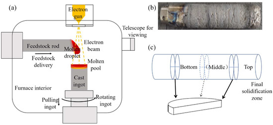
Figure 1.
Principle of EBM and rod materials. (a) Schematic diagram of EBM; (b) DZ125 revert ingot; (c) sampling schematic diagram.
The morphological structures of ingot top slag, final solidification zone surface, and final solidification zone cross-section were observed using a Zeiss Supra55 field-emission scanning electron microscope (SEM, Zeiss, Oberkochen, Germany). Chemical compositions were analyzed by energy-dispersive spectroscopy (EDS), and phase analysis was conducted via X-ray diffractometer. To investigate the effect of electron-beam refining on alloy composition, systematic sampling and analysis were performed on alloy samples before and after refining. The cross-sectional sampling method is shown in Figure 1c. The ingot produced at 36 kW was sampled in three parts (upper, middle, and lower), while ingots at 40 kW and 46 kW were divided into upper and lower parts for sampling, due to their length. This sectional sampling allowed for understanding of the distribution of inclusions and impurity element contents at different ingot positions, thereby analyzing the influence of melting power on inclusion distribution and impurity element contents. The oxygen, nitrogen, and sulfur impurity contents in alloys prepared under different melting power parameters were detected by glow discharge mass spectrometry and an oxygen–nitrogen analyzer.
3. Results and Discussion
3.1. Surface Morphology and Composition of Slag on Ingot Top
The slag at the top of ingots derived from electron-beam remelting of DZ125 scrap was characterized, with its morphology shown in Figure 2a. Figure 2b depicts the upper surface of slag directly exposed to the furnace internal environment, where a layer of fine granular substances was observed to cover the surface. Figure 2c shows the contact surface between slag and crucible, which is generally smooth, but accumulates abundant white impurities.
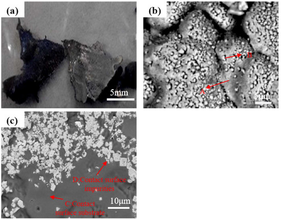
Figure 2.
The slag top of the ingot. (a) Morphology of slag; (b) upper surface of slag; (c) contact surface between slag and crucible.
Table 2 summarizes the energy-spectrum analysis results of the slag. Both the matrix on the upper slag surface (referred to as A) and the particles covering the matrix (referred to as B) contain the same elemental species with close contents, including main alloying elements of DZ125 scrap such as Cr and Ni, indicating obvious volatilization of major alloying elements during electron-beam remelting. The presence of the O element in the slag suggests that part of the dissolved oxygen or oxygen from oxides was released from the alloy during electron-beam remelting. Compared with the matrix on the upper surface, the matrix composition of the contact surface between slag and crucible (referred to as C) contains additional elements of Mo, Ti, Hf, Ta and W, with significantly reduced O content. The white impurities covering the contact surface (referred to as D) also contain the C element, but no O element is detected. Based on the high contents of Ta, Hf, and C in the impurities, they are speculated to be MC-type carbides. Heavy elements such as Ta and Hf with low volatility are enriched on the contact surface, thus forming MC-type carbides with the C element.

Table 2.
The EDS results of the slag (wt.%).
3.2. Surface Morphology and Composition Analysis of the Ingot Final Solidification Zone
The surface of the final solidification zone in the DZ125 directionally solidified ingot is shown in Figure 3a. Combined with energy spectrum analysis, the core of the final solidification zone, in addition to the matrix, also contains HfO2, Al2O3, and MC-type carbides rich in Ta and Ti (Table 3).
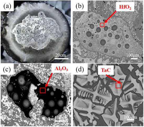
Figure 3.
SEM images of inclusions in the final solidification zone. (a) Macroscopic morphology of the final solidification zone; (b) HfO2; (c) Al2O3; (d) TaC.

Table 3.
The EDS spectrum of the surface inclusions in the final solidification zone (wt.%).
Phase analyses of the final solidification zone surfaces were conducted for DZ125 scrap after electron-beam drop melting at different powers (36 kW, 40 kW, and 46 kW), with results shown in Figure 4. The surface of the final solidification zone after 36 kW electron-beam melting contains substances such as HfO2, TaC, and Al2O3. However, Al2O3 was not detected on the surfaces of the final solidification zones after electron-beam melting at 40 kW and 46 kW. This may be attributed to the decomposition of Al2O3 promoted by the increased temperature with higher melting power, or the fact that it was encapsulated by HfO2, and thus not detected.
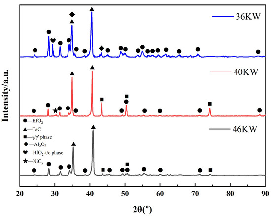
Figure 4.
XRD patterns of the surface of the final solidification zone of the ingot.
3.3. Cross-Sectional View and Composition Analysis of the Final Solidification Zone
Figure 5a shows the cross-sectional microstructure of the final solidification zone, with the edge and core regions arranged sequentially from left to right. Figure 5b,c present enlarged views of the edge and core regions, respectively, where large-sized irregular filamentous HfO2 is observed to encapsulate fine Al2O3 particles. Due to the high density of HfO2, which hinders its upward migration to the surface, the overall density decreases after encapsulating Al2O3, facilitating its upward floating to the surface and solidification in the surface and near-surface layers of the final solidification zone. The observation of refractory oxides in the final solidification zone indicates the presence of an oxide floating mechanism for removing inclusions from the ingot, and the underlying mechanism will be specifically analyzed in the subsequent sections.
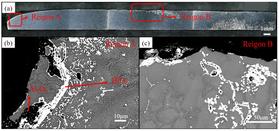
Figure 5.
Cross-sectional view and microstructural analysis of the final solidification zone. (a) Macroscopic cross-sectional view of the final solidification zone; (b,c) microstructural analysis of different regions.
3.4. Oxides and Impurity Elements in the Middle Region of the Ingot
Inclusion-induced local stress concentration under applied stress readily triggers crack initiation and propagation in superalloys, detrimentally affecting their mechanical properties. Investigating inclusion morphology and developing inclusion-removal strategies are therefore critical for enhancing superalloy quality and performance. This study characterized changes in inclusion size, number, distribution, and contents of O, N, and S elements before and after electron-beam refining.
Figure 6 shows inclusion morphologies after induction melting, 36 kW EBM, and 40 kW EBM, with inclusion types identified via energy spectrum analysis shown in Table 4. The white irregular inclusions are HfO2, and the black irregular inclusions are Al2O3.
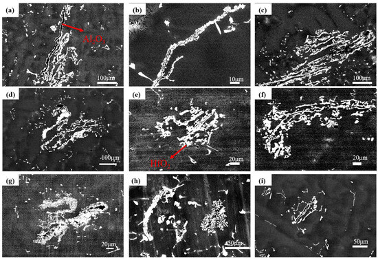
Figure 6.
Morphology of inclusions. (a–c) Induction-melted ingot; (d–f) ingot after 36 kW EBM; (g–i) ingot after 40 kW EBM.

Table 4.
The EDS results of inclusions in the solidification zone (wt.%).
Statistics were conducted on the size and quantity of internal oxides in as-cast ingots from induction raw materials and under different electron-beam melting powers. As previously mentioned, the 36 kW electron beam-cast ingots were longer, so the upper, middle, and lower sections were statistically analyzed respectively, while the 40 kW and 46 kW electron beam-cast ingots were statistically analyzed at the upper and lower sections. Each section was characterized by the core, half-radius, and edge regions. The results are listed in Table 5. Overall, with the increase in melting power, the size and quantity of internal oxides in electron beam-cast ingots decreased.

Table 5.
Statistical analysis of inclusion size and quantity in different regions of the ingot.
Based on the comparison of inclusion counts between the as-cast ingot and the 36 kW EBM-processed ingot in Table 5, the residual inclusions under low-power conditions are predominantly undissolved large original particles, accounting for approximately 54.5%.This observation is further supported by the morphological consistency of inclusions in Figure 6: both the inclusions in the original revert ingot (Figure 6a–c) and those in the EBM-refined ingot (Figure 6d–i) are identified as irregularly shaped HfO2 (white) and Al2O3 (black), via EDS analysis. Such consistency in morphology and composition confirms that these residual inclusions are directly inherited from the revert electrode without complete dissolution during the low-power EBM process.
To investigate the effect of electron-beam melting power on impurity element removal, bar charts of O/N/S contents before and after electron-beam melting are plotted in Figure 7. The results show that electron-beam melting significantly reduces impurity element contents, with remarkable removal efficiency for O and N, while S content remains nearly unchanged. Higher melting power correlates with lower O and N concentrations, though N content slightly rebounds at 46 kW, yet remains below the as-received level. The total content of O + N + S decreases with increasing melting power, confirming that electron-beam melting effectively purifies the material. Within the 36–46 kW power range, higher power enhances impurity-removal efficiency. When the melting power exceeds 40 kW, N content drops below 5 ppm, and O + N + S content falls below 10 ppm, demonstrating that electron-beam drop melting of DZ125 scrap at elevated power meets the purity requirements for superalloys, thus enabling practical reuse of DZ125 scrap.
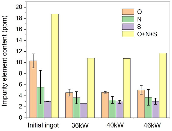
Figure 7.
Column diagram of impurity element content.
3.5. Mechanism of Oxide Removal from DZ125 Revert Material
Oxygen in DZ125 revert material primarily exists as oxides such as HfO2 and Al2O3. During EBM, the oxide removal mechanisms are mainly migration–flotation and decomposition.
The dominant melt flow mechanism in EBM is the Marangoni effect, which arises from surface tension gradients [21,22]. Regions with higher surface tension exert tensile forces on adjacent lower-tension regions, driving liquid flow from low-tension to high-tension areas. Additionally, a temperature gradient exists on the melt surface (higher at the center, lower at the edges), generating a surface tension gradient. For temperature gradients with the surface tension gradient dγ/dT < 0, inclusions migrate from the low-surface-tension central region to the high-surface-tension edge, along with the melt flow. The flow direction of Marangoni convection also depends on surface-active elements (e.g., O, S). When the content of these elements reaches a critical level, dγ/dT becomes positive, reversing the Marangoni flow direction and causing inclusions to migrate from the edge to the center. The melt flow pattern is shown in Figure 8a,b.
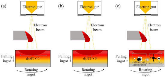
Figure 8.
Direction of melt flow and stress on inclusions. (a) Schematic diagram of melt flow under Marangoni effect when dγ/dT < 0; (b) schematic diagram of melt flow under Marangoni effect when dγ/dT > 0; (c) schematic diagram of melt flow direction and inclusion force under centrifugal force, in which the black spheres are Al2O3 and the white spheres are HfO2.
The density relationship between Al2O3 and HfO2 is crucial for enhancing the buoyancy-driven removal of inclusions. As illustrated in Figure 5, high-density HfO2 particles are frequently encapsulated within low-density Al2O3 particles, forming composite inclusions. This encapsulation behavior is key to reducing the overall density of the inclusions: given that the density of the DZ125 alloy melt is 8.595 g/cm3, and the density of Al2O3 (≈3.97 g/cm3) is lower than that of HfO2 (≈9.68 g/cm3), the average density of the composite inclusions is reduced, thereby promoting their upward flotation under the action of buoyancy. Through theoretical calculations, the minimum Al2O3 dilution ratio required for density reduction is 28%. The encapsulation morphology in Figure 5 shows that even partial encapsulation of HfO2 by Al2O3 is sufficient to reduce the density of the composite inclusions below that of the alloy melt. This conclusion is directly confirmed by the migration of composite inclusions to the final solidification zone (rather than remaining in the ingot interior), indicating that the proportion of Al2O3 in the composite inclusions meets the requirement for density reduction.
Notably, the agglomeration of inclusions (i.e., the collision and clustering of HfO2 and Al2O3 particles) occurs before the alloy leaves the electrode. During EBM, the high-energy electron beam first melts the feedstock rod into molten droplets, which then fall into the lower molten pool (Figure 1a). Throughout this process, Marangoni convection induced by surface tension gradients, turbulent stirring from droplet falling, and centrifugal forces from ingot rotation, collectively drive intense flow within the molten pool. This flow promotes frequent collisions between HfO2 (high-density) and Al2O3 (low-density) particles—primarily Stokes collisions, where HfO2 particles aggregate around Al2O3 cores—prior to the alloy’s solidification and separation from the electrode. Once agglomerated, the composite inclusions with reduced average density then float upward under buoyancy, rather than undergoing agglomeration after the alloy exits the electrode.
Li calculated the relationship between the surface tension of DZ125 alloy melt, temperature, and surface active-element content [23]. When the contents of O and S elements in the alloy are both 10 ppm, the corresponding critical temperature is 2000 K. The DZ125 alloy revert used in the experiment contains 9.4 ppm of O and 2.9 ppm of S, giving a critical temperature lower than 2000 K. The minimum EBM power used in this study is 36 kW, generating a temperature higher than the critical temperature, indicating that the melt on the surface of DZ125 alloy flows toward the edge region. Compared with the inward flow region at the edge, the outward flow area at the center is larger. Such flow reversal leads to collision and agglomeration of inclusions in the molten pool.
Large-sized inclusions migrate to the surface under buoyancy, while small particles primarily move with melt convection, and grow through collisions. Three collision mechanisms exist among inclusions: Brownian collision arises from the random thermal motion of smaller particles [24,25]; Stokes collision occurs when larger inclusions with higher buoyancy velocities overtake and capture smaller ones, due to density differences between the melt and inclusions [26,27,28]; and turbulent collision results from turbulent eddies in the melt [26,29,30]. Shu reported that increasing temperature and enhancing agitation promote inclusion collisions. Turbulent collisions dominate the initial aggregation stage, forming clusters. Once agglomerated, Stokes forces become pivotal for lifting these clusters. The Marangoni effect and high surface temperatures increase collision frequencies, accelerating aggregation.
Droplet melting stirs the molten pool, inducing turbulent collisions and clustering. Light-density Al2O3 inclusions float to the surface, due to buoyancy. As previously observed, white HfO2 encapsulates black Al2O3, suggesting Stokes collisions between them: dense HfO2 particles aggregate around lighter Al2O3 cores, reducing the composite density and enabling flotation. Additionally, centrifugal forces from the rotating ingot affect inclusion distribution. The melt flow pattern and inclusion forces are illustrated in Figure 8b. Small inclusions collide and grow during convection, while large ones are influenced by gravity, buoyancy, and drag forces. During melting, centrifugal forces cause low-density oxide inclusions to accumulate toward the ingot center.
The high energy density of the electron beam induces melting or decomposition of inclusions. According to Li’s calculations [23], the minimum temperature for superheated melting of HfO2 in the DZ125 alloy is 2392.8 K, which exceeds the thermal melting temperature of Al2O3 but remains lower than the maximum molten pool temperature (2488.9 K) achieved at an electron-beam power of 14 kW. In this study, the minimum melting power is 36 kW, indicating that both HfO2 and Al2O3 inclusions can be removed via melting. Gong investigated the decomposition of various nitrides and oxides under high-temperature vacuum conditions, reporting that Al2O3 decomposes at temperatures below 1700 K under 0.1 Pa. Given the experimental vacuum level of 0.1–0.001 Pa and melting temperatures achieved at 36 kW or higher, Al2O3 decomposition is thermodynamically feasible.
4. Conclusions
- (1)
- After EBM of DZ125 revert material, the morphology and composition of the slag at the top of the ingot were analyzed. Volatilization of major alloying elements occurred, while MC-type carbides (TaC and HfC) formed at the interface between the slag and crucible. The final solidification zone of the ingot contained oxides such as HfO2, TaC, and Al2O3, with HfO2 encapsulating Al2O3 particles, indicating that inclusions in the melt migrated to the ingot surface during melting.
- (2)
- Inclusions in the ingot were primarily HfO2 and Al2O3. As the EBM power increased, both the quantity and size of inclusions decreased, accompanied by reduced concentrations of interstitial impurities (O, N, S).
- (3)
- Oxide inclusions were removed via two primary mechanisms: flotation and dissolution. Marangoni convection, droplet stirring, and centrifugal forces induced by the rotating ingot facilitated inclusion migration. Collision and agglomeration of inclusions occurred, with HfO2 aggregating around less dense Al2O3 particles, promoting their flotation, due to buoyancy. Additionally, the high-temperature, high-energy, and high-vacuum environment of EBM enabled the decomposition of HfO2 and Al2O3, further enhancing inclusion removal.
Author Contributions
X.Z.: Writing—original draft. X.W.: methodology. L.G.: conceptualization. Y.W.: writing—review and editing. J.X.: formal analysis. X.H.: writing—review and editing. All authors have read and agreed to the published version of the manuscript.
Funding
This work was supported by the National Key R&D Program of China (No. 2022YFB3705003), the Self-innovation Special Fund Project of Aero Engine Corporation of China (ZZCX-2022-040), and the Advanced Materials—National Science and Technology Major Project (2024ZD0600600).
Data Availability Statement
The original contributions presented in this study are included in the article. Further inquiries can be directed to the corresponding authors.
Conflicts of Interest
Author Jianing Xue was employed by the company Materials Research Institute, Beijing Beiye Functional Materials Corporation. The remaining authors declare that the research was conducted in the absence of any commercial or financial relationships that could be construed as a potential conflict of interest.
References
- Long, H.B.; Mao, S.C.; Liu, Y.N.; Zhang, Z.; Han, X.D. Microstructural and compositional design of Ni-based single crystalline superalloysd—A review. J. Alloys Compd. 2018, 743, 203–220. [Google Scholar] [CrossRef]
- Theska, F.; Street, S.R.; Lison-Pick, M.; Primig, S. Grain boundary microstructure-property relationships in the cast & wrought Ni-based superalloy Ren’e 41 with boron and carbon additions. Acta Mater. 2023, 258, 11. [Google Scholar]
- Wu, Y.T.; Li, C.; Xia, X.C.; Liang, H.Y.; Qi, Q.Q.; Liu, Y.C. Precipitate coarsening and its effects on the hot deformation behavior of the recently developed γ′-strengthened superalloys. J. Mater. Sci. Technol. 2021, 67, 95–104. [Google Scholar] [CrossRef]
- Dong, G.Y.; Yiliti, Y.; Liu, X.Y.; You, X.G.; Han, W.J.; Dong, L.Y.; Chang, K.; Zhou, H.J.; Li, P.T.; Wang, Y.N. Mechanisms for removing impurities in a single crystal superalloy by electron beam drip melting. J. Mater. Res. Technol.-Jmr&T 2024, 28, 13. [Google Scholar]
- Farahani, H.; Melali, P.; Divandari, M. Study the Effects of Casting Revert-Virgin Alloy with Different Portion of Return (Revert) Materials on Microstructure, Mechanical Properties, and Creep Resistance of Inconel 713LC. Int. J. Met. 2025, 19, 432–444. [Google Scholar] [CrossRef]
- Yang, Y.H.; Yu, J.J.; Sun, X.F.; Jin, T.; Guan, H.R.; Hu, Z.Q. Effect of revert addition on microstructure and mechanical properties of M951 Ni-base superalloy. Mater. Sci. Eng. A-Struct. Mater. Prop. Microstruct. Process. 2012, 532, 6–12. [Google Scholar] [CrossRef]
- Zhang, K.; Zhang, J.S.; Zhao, P.; Chen, Z.X.; Jiang, Z.Y.; Liu, Q.; Yang, S.F. Microstructure and high temperature tribological behavior of nickel-based superalloy with addition of revert. J. Mater. Res. Technol.-Jmr&T 2024, 33, 1934–1945. [Google Scholar]
- Hu, Y.B.; Zhang, L.; Cheng, C.Q.; Zhao, P.T.; Guo, G.P.; Zhao, J. Oxidation Behavior of the Nickel-Based Superalloy DZ125 at 980 °C. Acta Metall. Sin.-Engl. Lett. 2017, 30, 857–862. [Google Scholar] [CrossRef]
- Sun, H.F.; Tian, S.G.; Tian, N.; Yu, H.C.; Meng, X.L. Microstructure heterogeneity and creep damage of DZ125 nickel-based superalloy. Prog. Nat. Sci. 2014, 24, 266–273. [Google Scholar] [CrossRef]
- Wang, C.S.; Zhang, J.; Liu, L.; Fu, H.Z. Microstructure evolution of directionally solidified DZ125 superalloy with melt superheating treatment. J. Alloys Compd. 2010, 508, 440–445. [Google Scholar] [CrossRef]
- Wang, S.F.; Ditta, A.; Xu, Y.; Zhang, Z. Effect of microstructures restoration on high temperature fatigue behavior of DZ125 superalloy. Prog. Nat. Sci. 2021, 31, 633–640. [Google Scholar] [CrossRef]
- Otubo, J.; Rigo, O.D.; Neto, C.M.; Mei, P.R. The effects of vacuum induction melting and electron beam melting techniques on the purity of NiTi shape memory alloys. Mater. Sci. Eng. A 2006, 438–440, 679–682. [Google Scholar] [CrossRef]
- Kalinyuk, A.N.; Trigub, N.P.; Zamkov, V.N.; Ivasishin, O.M.; Markovsky, P.E.; Teliovich, R.V.; Semiatin, S.L. Microstructure, texture, and mechanical properties of electron-beam melted Ti–6Al–4V. Mater. Sci. Eng. A 2003, 346, 178–188. [Google Scholar] [CrossRef]
- Li, B.K.; Huang, X.C.; Liu, Z.Q.; Zhao, F.S.Q.; Yi, L.; Wang, Y.N. Characteristics and evolution of advanced modern electroslag remelting technologies. Iron Steel 2022, 57, 1–11. [Google Scholar]
- Haruna, Y.; Mitchell, A.; Schmaltz, A.J. Some Observations on the Recycling of Superalloys by the EBCHM Process. High Temp. Mater. Process. 1995, 14, 173–191. [Google Scholar] [CrossRef]
- Li, Y.; Tan, Y.; Wang, D.G.; You, X.G.; Chen, Z.; Bai, R.S.; Qiang, J.B. Effect of electron beam melt superheating treatment on DZ125 alloy. J. Mater. Res. Technol.-Jmr&T 2023, 24, 6088–6106. [Google Scholar]
- Vutova, K.; Vassileva, V.; Koleva, E.; Georgieva, E.; Mladenov, G.; Mollov, D.; Kardjiev, M. Investigation of electron beam melting and refining of titanium and tantalum scrap. J. Mater. Process. Technol. 2010, 210, 1089–1094. [Google Scholar] [CrossRef]
- Yiliti, Y.; Dong, G.Y.; Liu, X.Y.; You, X.G.; Han, W.J.; Dong, L.Y.; Zhao, Y.Q.; Yi, L.; Wang, Y.N. The high temperature oxidation behavior of a superalloy prepared by vacuum induction melting and electron beam smelting: A comparative study. J. Mater. Res. Technol.-Jmr&T 2023, 25, 6977–6991. [Google Scholar]
- Dong, G.Y.; You, X.G.; Dong, L.Y.; Yiliti, Y.; Xu, Z.H.; Zhou, H.J.; Wang, Y.N.; Tan, Y. The inclusion removal behavior during electron beam smelting of DD98M alloy. J. Mater. Res. Technol.-Jmr&T 2022, 20, 4297–4305. [Google Scholar]
- Niu, S.; You, Q.; You, X.; Shi, S.; Wang, Y.; Tan, Y. Mechanism of impurities reduction and evaporation of alloying elements for a multi-elements Ni-based superalloy during electron beam remelting. Vacuum 2018, 156, 345–350. [Google Scholar] [CrossRef]
- Lee, P.D.; Quested, P.N.; McLean, M. Modelling of Marangoni effects in electron beam melting. Philos. Trans. R. Soc. A-Math. Phys. Eng. Sci. 1998, 356, 1027–1043. [Google Scholar] [CrossRef]
- Niu, S.; Yin, K.; You, Q.; You, X.; Wang, Y.; Tan, Y. The alloying elements dispersion and its mechanisms in a Ni-based superalloy during electron beam remelting. Vacuum 2019, 166, 107–113. [Google Scholar] [CrossRef]
- Li, Y.; Tan, Y.; Zhao, J.; Dong, G.; Li, P.; Qiang, J. Technical research on recycling waste blades of single crystal superalloy through ultrasonic alkali cleaning combined with electron beam smelting. Sep. Purif. Technol. 2024, 331, 125585. [Google Scholar] [CrossRef]
- Ferguson, J.B.; Schultz, B.F.; Rohatgi, P.K.; Kim, C.-S. Impact of Brownian motion on the particle settling in molten metals. Met. Mater. Int. 2014, 20, 747–755. [Google Scholar] [CrossRef]
- Lei, H.; He, J. Nucleation and Growth Kinetics of MgO in Molten Steel. J. Mater. Sci. Technol. 2012, 28, 642–646. [Google Scholar] [CrossRef]
- Gao, X.; Zhang, L.; Luan, Y.; Chen, X.; Qu, X. Investigation of Inclusion Agglomeration and Flotation During Levitation Melting of Ni-Based Superalloy in a Cold Crucible. JOM 2020, 72, 3247–3255. [Google Scholar] [CrossRef]
- Liu, N.; Liu, F.; Yang, W.; Chen, Z.; Yang, G.C. Movement of minor phase in undercooled immiscible Fe–Co–Cu alloys. J. Alloys Compd. 2013, 551, 323–326. [Google Scholar] [CrossRef]
- Zhang, L.; Yu, G.; He, X.; Li, S.; Ning, W.; Wang, X. Phase separated characteristics affected by cooling rate of immiscible Cu-Cr alloy by laser surface melting. J. Alloys Compd. 2019, 772, 209–217. [Google Scholar] [CrossRef]
- Ba, Q.; Liu, X.; Yang, Y.; Wang, W. Motion behavior and removal mechanism of inclusions during negative pressure continuous casting process. J. Mater. Sci. 2022, 57, 21502–21518. [Google Scholar] [CrossRef]
- Chang, K.; Tan, Y.; Bai, R.; Dong, G.; Li, P.; Liu, Y.; Yuan, H.; Wang, Y. Research on directional solidification combined with electron beam melting and refining for recycling of FGH4096 alloy scraps. Sep. Purif. Technol. 2024, 351, 127874. [Google Scholar] [CrossRef]
Disclaimer/Publisher’s Note: The statements, opinions and data contained in all publications are solely those of the individual author(s) and contributor(s) and not of MDPI and/or the editor(s). MDPI and/or the editor(s) disclaim responsibility for any injury to people or property resulting from any ideas, methods, instructions or products referred to in the content. |
© 2025 by the authors. Licensee MDPI, Basel, Switzerland. This article is an open access article distributed under the terms and conditions of the Creative Commons Attribution (CC BY) license (https://creativecommons.org/licenses/by/4.0/).