Article

Development of a Laser Cladding Technology for Repairing First-Stage High-Pressure Turbine Blades in Gas Turbine Engines

Department of Digital Industrial Technology, Saint-Petersburg State Marine Technical University, St. Petersburg 190000, Russia
*
Author to whom correspondence should be addressed.
Metals 2025, 15(9), 957; https://doi.org/10.3390/met15090957
Submission received: 18 June 2025 / Revised: 19 August 2025 / Accepted: 23 August 2025 / Published: 28 August 2025
(This article belongs to the Section Additive Manufacturing)

Abstract

A gas turbine engine is a technological system consisting of a compressor, a combustion chamber, and other modules. All these components are subjected to dynamic and cyclic loads, which lead to fatigue cracks and mechanical damage. The aim of this work is to repair the worn surfaces of a series of DR-59L high-pressure turbine blades by laser powder cladding. A number of technological parameters of laser cladding were tested to obtain a defect-free structure on the witness sample. The metal powder of the cobalt alloy Stellite 21 was used as a filler material. By modeling the process of restoring rotor blades, the operating mode of laser powder cladding was determined. No defects were detected during capillary control of the restored surfaces of the rotor blades. The results of the uniaxial tension test of the restored rotor blades showed increased tensile strength and elongation. With the use of laser powder cladding technology, it was possible to restore the worn surfaces of a series of rotor blades of the DR-59L high-pressure turbine, thereby increasing the life cycle of power plant products.

1. Introduction

Currently, laser processing of materials is becoming increasingly important in various industries due to the expansion of the scope of application of laser equipment. Automotive, aerospace, naval, military, and many other industries make extensive use of laser technology for welding, cutting, and quenching. Among the applied laser technologies, laser cladding (LC) has attracted considerable interest in recent years due to its versatility in material processing, such as metal coating, precision repair of parts, prototyping, and even small-scale production [1].
The design of the impellers is crucial for the efficient operation of a gas turbine engine (GTE), as they are the most heavily loaded, important, and versatile parts. The blades have requirements for static and multi-cycle fatigue damage, high-temperature oxidation, and creep resistance, as well as corresponding requirements for gas-dynamic efficiency; therefore, the manufacture of GTE rotor blades is a complex metallurgical, technological, and design task [2].
The rotor blades of gas turbine engines are the parts with the highest strength indices and are subjected to the most intense operating conditions: high speeds across various temperatures; high aerodynamic friction and various types of debris (sand, rain); and static, dynamic, and cyclic loads that cause fatigue cracking, thermal stresses, and mechanical damage. Cracks often originate at the exit edges of the blades, developing perpendicular to them, and at the root of the blades in the tail. All these factors shorten the service life of the blades and increase the likelihood of premature damage, leading to significant safety problems and financial losses [3].
The restoration of the rotor blades of a gas turbine engine requires special conditions such as low heat generation, local and precise addition of material, and fusion with heat-resistant alloys that are difficult to weld. LC technology makes it possible to fulfill all the specific conditions required for the restoration of gas turbine engine components. Currently, LC is well known as the best solution for repairing damaged blades of gas turbine engines. Numerous studies are being conducted to improve the repair process of a gas turbine engine by developing new additives, optimizing parameters, and automating the process [4,5,6].
Repair work usually includes the following steps: collection of damaged areas, restoration of geometry, machining, and heat treatment [7]. LC, argon arc surfacing, and direct laser spraying are the most common technologies used to repair the rotor blades of nickel-based high-pressure turbines. The choice of technology depends on the size and shape of the detected defects [8,9,10,11,12,13].
The authors of [14] described the use of the argon arc welding method with a permanent electrode to restore the shell of nickel-based heat-resistant rotor blades with a pulse coating of a heat-resistant alloy, which ensures high process performance. The stability of this process was maintained by adding cladding metal templates of constant size and thickness. In addition, JS6K alloy blades were sintered in argon for 3 h at 950 °C, followed by dye penetrant testing to detect defects such as cracks or peeling.
In addition to the above methods, the use of argon arc surfacing technology for the repair of gas turbine blades made of nickel and cobalt alloys was described in [15]. First, the blades were cleaned of defective material and chamfered, then heated in a vacuum furnace for 3 h at a constant temperature, and then slowly cooled in a vacuum chamber to ambient temperature. In addition, the defective sections of the blades were treated with argon arc welding wire with EP-367 or EP-533 alloy additives, followed by mechanical treatment of the restored sections of the blades and sintering of the blades in an electric furnace in a controlled atmosphere for 5 h at a temperature of 840 °C. As a result, no cracks were found on the repaired blades at the melting points.
Moreover, in [16], the authors described the process of repairing the surfaces of IN738 alloy knife tips by argon arc surfacing, indicating that surfacing in automated mode significantly reduces the number of cracks per unit surface area in the heat treatment zone compared with surfacing in manual mode. This decrease is due to the ability to adjust the burner speed, wire feed, arc length, and current power in automatic mode but is limited by the difficulties of restoring the geometry of worn blades. The input parameters of the surfacing process require adjustment in accordance with changes in the thickness of the blade profile, minimizing the formation of cracks and maintaining a constant geometry of the melt pool.
Another remarkable method was described in [17], where the authors used LC powder to restore a gas turbine engine blade made of IN738 alloy. An IN625 alloy powder was used as an additive. The authors pointed out that cracks formed near the boundaries of the metal grains of the blade, in the heat treatment area, if the blade was not preheated. In addition, the use of an IN738 alloy additive has shown better results in restoring areas with low deformation compared to the above methods, so the choice of additive material depends on the design of the damaged blade. The experimental results showed the same microstructure, hardness, and rate of fatigue crack growth for both deposited and primary blade materials after appropriate heat treatment.
The authors of [18] described the use of the LC powder method to reconstruct the geometry of a turbine blade made of a heat-resistant alloy. The optimal technological regime was obtained on the basis of computer simulation of the blade surfacing process, taking into account the temperature conditions in the main blade material. In addition, the technological regime with the addition of IN718 alloy was determined and refined on the substrate, taking into account the geometry of the rotor blade. The authors reported the final restoration of the worn blade with a slight increase in size.
The authors of [19] demonstrated that laser powder coating technology makes it possible to repair the pen of the rotor blade of a first-stage gas turbine, without defects, made of GTD 111 alloy. The heat-resistant nickel alloy Rene 65 was used as a filler material, and the coating was carried out without preheating the treated surface. According to the results of metallography, equiaxed dendritic growth was observed without a certain crystallographic alignment. With an increase in the laser radiation power and the speed of movement, the microhardness in the heat-affected zone increased, whereas with the use of a reversible surfacing strategy, the microhardness increased even more.
Finally, in [20], the authors demonstrated the possibility of repairing a turbine blade made of a heat-resistant alloy by laser powder coating with the addition of Stellite 6 alloy powder. To minimize blade deformation, the following technological conditions were set: minimizing heat consumption by adjusting low laser power, preventing heat accumulation at the edges, and minimizing the thickness of the deposited layer. Changing the surfacing parameters, such as the powder consumption, laser power, and surfacing speed, can lead to the formation of porosity in the material, which reduces its wear resistance and can lead to surface defects. The formation of porosity is associated with a lack of energy required for the complete melting of the deposited layer due to the high ratio of the height of the powder layer to its width.
To further increase the service life and reliability of parts, wear-resistant alloys are applied to surfaces that are heavily worn during operation. Cobalt-based alloys have good mechanical, thermal, and chemical properties, especially at high temperatures. Upon solidification, cobalt alloys of the Stellite class acquire a dendritic microstructure containing carbides with different morphologies. The preferred plane of dendrite growth lies approximately perpendicular to the surface, although dendrites can grow in different directions in this plane. The improved performance properties are due to a more uniform microstructure during liquid crystal deposition compared to traditional surfacing methods. The surfacing properties can be further improved by adding carbides, nitrides, and borides to Stellite alloys. For example, hardness and wear resistance increase linearly with an increase in the volume fraction of the carbides present in the coating [21].
Summarizing the above examples, we can say that the demand for LC technology in various industries is growing, and the corresponding technology is considered a modern method of restoring parts worn during operation, since the topic of repairing worn components of a gas turbine engine is still relevant. The purpose of this work is to restore the worn elements of the rotor blades (locking-piece ends, sealing crests, and blades) of the first stage of the high-pressure turbine GTE DR-59L, made of heat-resistant nickel alloy ChS-70, by laser powder coating with cobalt alloy Stellite 21 for subsequent reuse. In accordance with the purpose of the work, the operating mode of surfacing was determined, ensuring defect-free formation of rollers, strategies for surfacing elements of the rotor blades were developed, and mechanical tests of witness samples were carried out.

2. Materials, Methods, and Equipment

2.1. Rotor Blade of the GTE DR-59L

Restoration work was carried out on the high-pressure turbine blades of the DR-59L GTE (Basic Mechanical Engineering, Tyumen, Russia), which is made of heat-resistant nickel alloy ChS-70. The rotor blades were manufactured by casting in ceramic molds. Parts made of this alloy operate for a long time across various temperatures and stress intervals in aggressive environments. The chemical composition of the ChS-70 alloy is provided in Table 1.
High-pressure turbine rotor blade wear was evaluated through dimensional inspection with slide and height gauges. All measurements were performed on a vertically set blade, with the blade locking piece resting on an even surface. The dimensional sizes of the rotor blade 3D model, along with the spacing between the surfaces subjected to the most wear during operation, were measured prior to inspection using SolidWorks 2020 software. The rotor blade dimensions are shown in Figure 1, in mm.
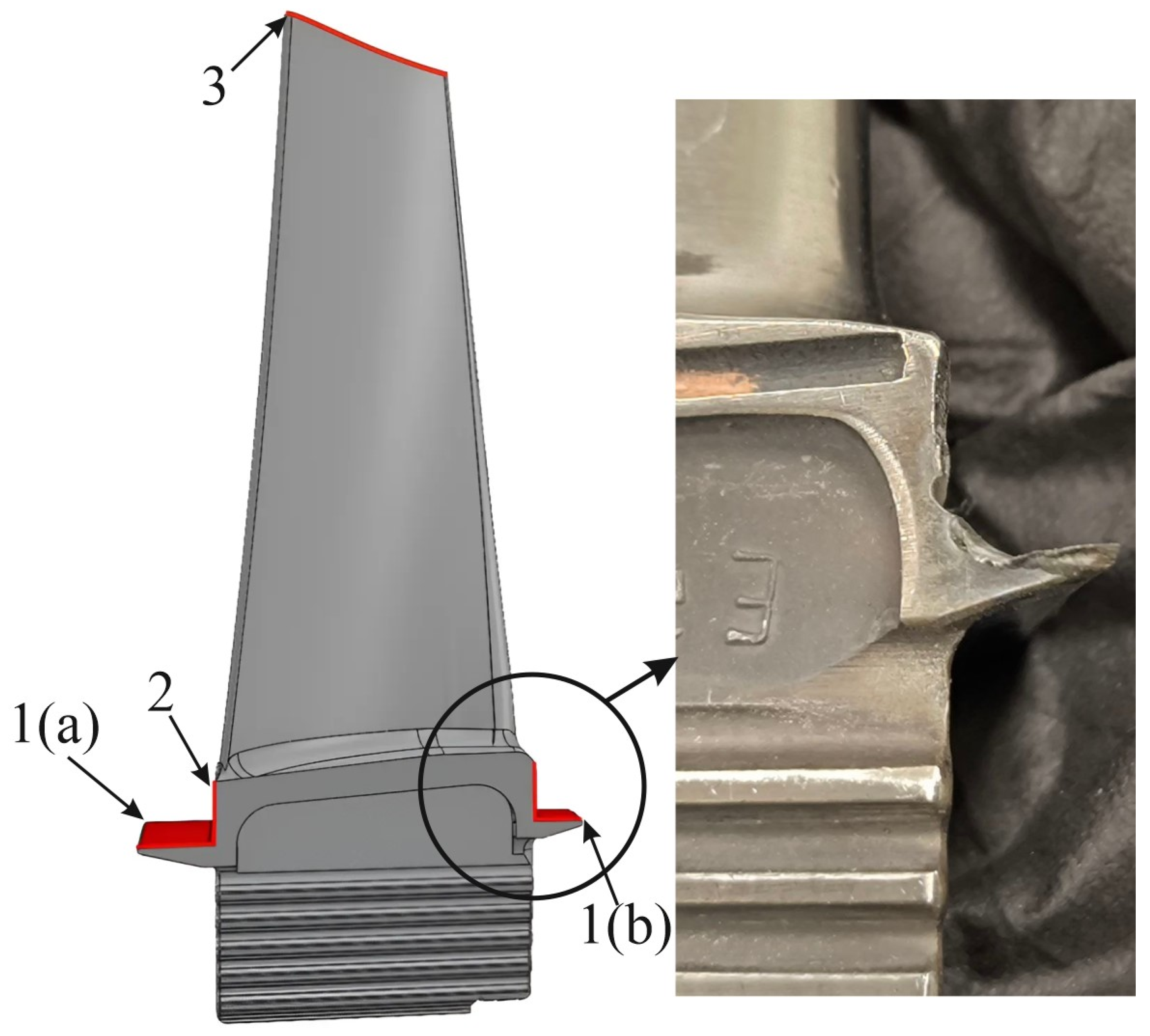
Comparison of the actual dimensions against the 3D model dimensions revealed that the worn areas were the locking-piece end (1), sealing crest (2), and blade (3), as shown in Figure 2 (worn areas are highlighted in red).

2.2. Description of Rotor Blade Heat Model

The thermal state of the rotor blade surface upon cladding was derived by solving the problem of transient heat conduction under exposure to a concentrated heat source. The heat conduction equation in three-dimensional space is as follows [22]:
ρ ( T ) C ( T ) T t = x λ ( T ) T x + y λ ( T ) T y + z λ ( T ) T z ,
where ρ is the density, C is the heat capacity, and λ is the thermal conductivity coefficient.
The initial rotor blade temperature is equal to the ambient temperature ( T 0 ):
T ( x , y , z , t ) | t = 0 = T 0
The influence of laser power on cladding is modeled as a surface heat source, with the corresponding power density ( q L ) derived from the normal distribution law:
q L ( x , y ) = P η π r L 2 e x p x 2 + y 2 r L 2 ,
where P is the heat source power; η is the thermal efficiency of the heat source; r L is the effective radius of the heat source; and x , y are the orthogonal coordinates of the mobile system.
Therefore, the boundary conditions on the front surface of the computational domain are given by
λ T n = q L ( x , y )
The convective heat transfer to the environment at ( T 0 ) is set for the other surfaces [22] as
λ T n = h c ( T T 0 ) ,
where h c is the heat transfer coefficient.
The heat transfer Equation (1) regarding boundary conditions (4) and (5) for the actual rotor blade geometry was solved using the finite element method with the COMSOL Multiphysics (6.2 Build 339) software package.

2.3. Rotor Blade Cladding Material

The chemical composition of the Stellite 21 alloy used as an additive powder is provided in Table 2. There are satellites on the powder particles; the powder particles have a rounded (spherical) shape, and irregular particles are also found in the powder used. The particle size fraction is 40–150 μ m. The morphology of the metallic particles of Stellite 21 is shown in Figure 3 at magnifications of 500 μ m (a) and 200 μ m (b).
The choice of Stellite 21 as an additive material was due to its high corrosion and wear resistance, along with the durability of cobalt-based alloys, which are commonly used for the repair and enhancement of high-pressure turbine rotor blades.

2.4. Laser Cladding Equipment and Experimental Process

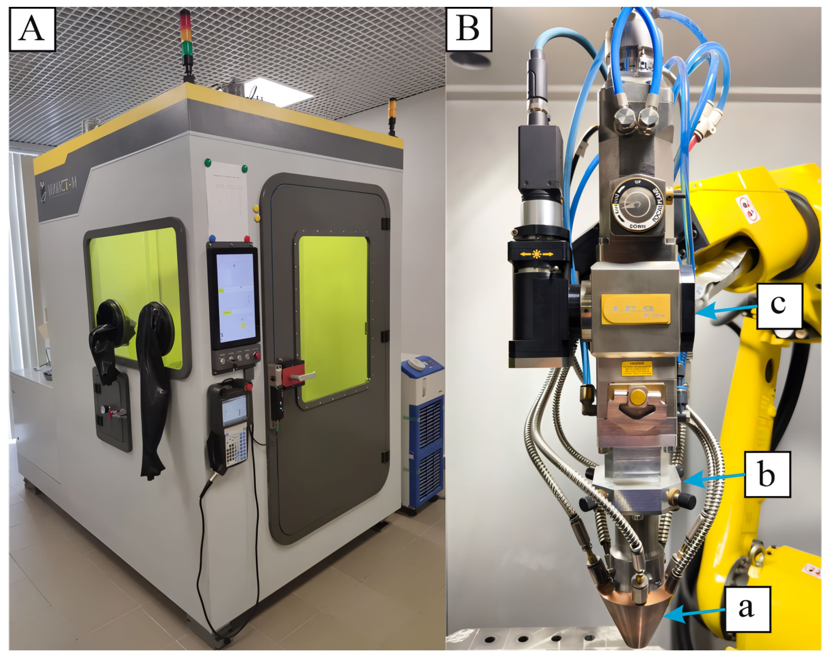
The ILWT-M unit for direct laser deposition, shown in Figure 4A, is utilized to repair worn rotor blades of GTEs. The actual unit is intended for the growth of metal items from metal powders and the cladding of worn parts; laser welding is possible if required.
The unit consists of a sealed chamber lined with steel sheets and containing a positioning assembly of a single-axial actuator and a six-axial industrial robot, the Fanuc M10iD/12 (Fanuc, Oshino, Japan). The robot flange is furnished with a process tool (Figure 4B) for transferring and focusing the laser beam within the cladding area, as well as supplying the process with an additive for cladding. The process tool comprises three main subassemblies: (a) a powder supply nozzle, (b) an adjustment unit, and (c) an optical welding head (IPG FLW D30L) (IPG Photonics, Marlborough, MA, USA). The power source in the cladding area is the built-in optical fiber laser IPG YLR-1500-U (IPG Photonics, Marlborough, MA, USA), and cooling is carried out by the SMC HRSH090-A-40 chilling system (SMC Corporation, Tokyo, Japan).
To determine the operating mode of cladding, a series of experimental studies were conducted by varying the technological parameters of laser cladding (power, velocity, and powder consumption), which are summarized in Table 3. Low values of laser radiation power (200–400 W) were selected in the experimental studies in order to prevent melting of the thin profile of the rotor blades.
Process samples were clad by varying the above-mentioned parameters. The process tool was orthogonal to the substrate, and the nozzle exit was offset from the substrate by 11 mm, maintaining a constant position throughout the process. The substrate material was ChS-70 alloy, and the additive material was Stellite 21 alloy. A compressed gas-powder jet was supplied coaxially to the laser beam from a jet nozzle; the carrier gas was argon. The control sample blade was clad in operational mode and then tested, including the following: non-destructive, metallurgical, strain, and microhardness testing. Non-destructive testing included capillary testing with Magnaflux Spotcheck SKC-S cleanser, Magnaflux SKD-S2 developer, and Magnaflux Spotcheck SKL-SP2 organo-soluble penetrant. The capillary control method was carried out according to ISO 3452-2:2009 [23].

2.5. Investigation of Sample Macrostructure

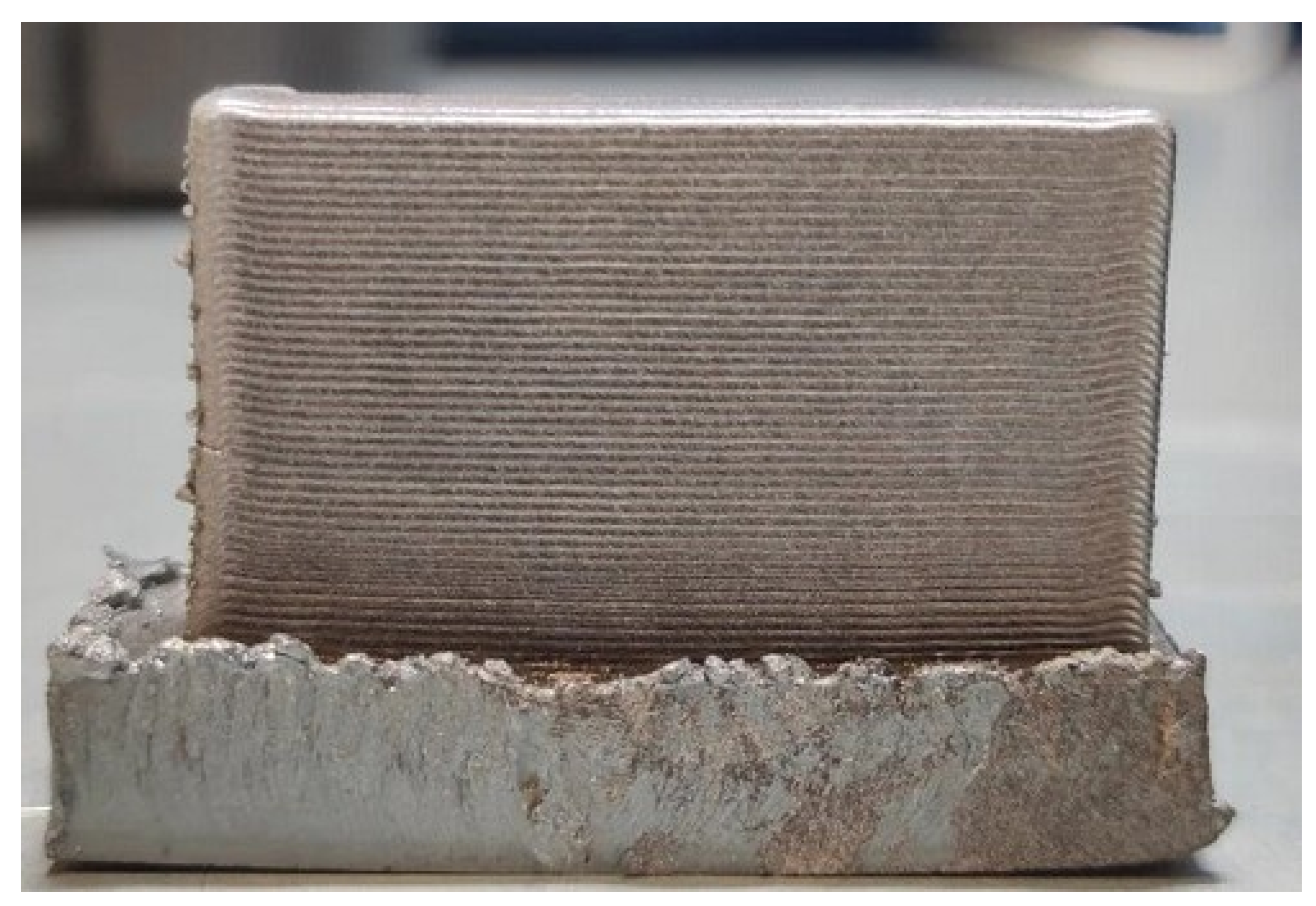
The clad samples (shown in Figure 5) were inspected visually for possible macroscopic defects (cracks, unstable areas).
At the end of the visual inspection, the deposited samples were prepared for further metallographic examination. The samples were prepared using a SAPHIR 250 A1-ECO grinding and polishing machine (QATM, Mammelzen, Germany). Sanding was performed on P120, P180, P600, P1200, and P2500 sandpaper discs. Polishing was carried out on polishing cloths with 9 microns, 6 microns, 3 microns, and 1 micron particle sizes. Etching was carried out using a solution of HCl and HNO3 in a 3:1 ratio. This acid mixture is known as “aqua regia”. The samples obtained in the framework of the experimental studies were examined using a Leica DMi8A inverted metallographic microscope (Leica Camera AG, Wetzlar, Germany) and a TESCAN MIRA 3 scanning electron microscope (TESCAN ORSAY HOLDING, Brno, Czech Republic).
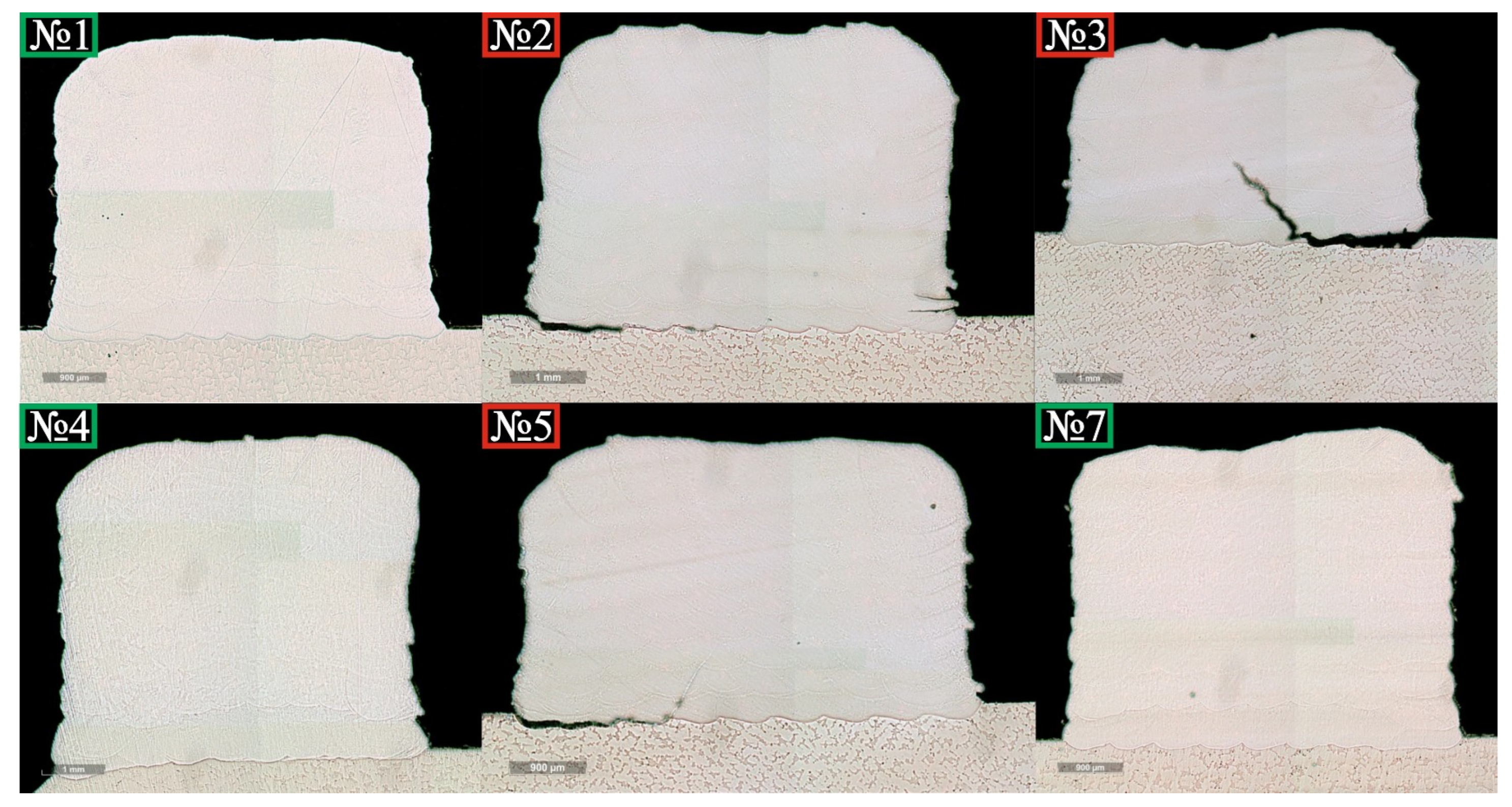
Macroscopic sections of the samples processed in various modes are shown in Figure 6.
As shown in the figure above, the samples processed in modes No. 1, No. 4, and No. 7 were free from defects, such as cracks and disbands, and exhibited constant layer thickness. In the sample obtained in mode No. 1, small pores were found, the number and size of which were within acceptable limits according to ISO 13919-1-2017 [24].

2.6. Mechanical Testing Equipment

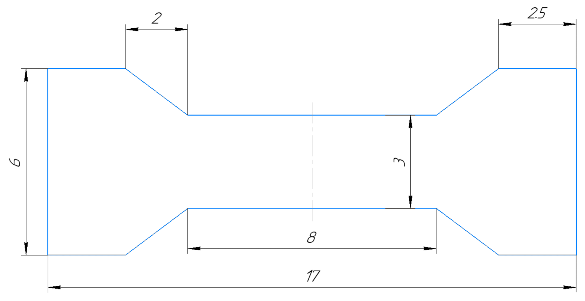
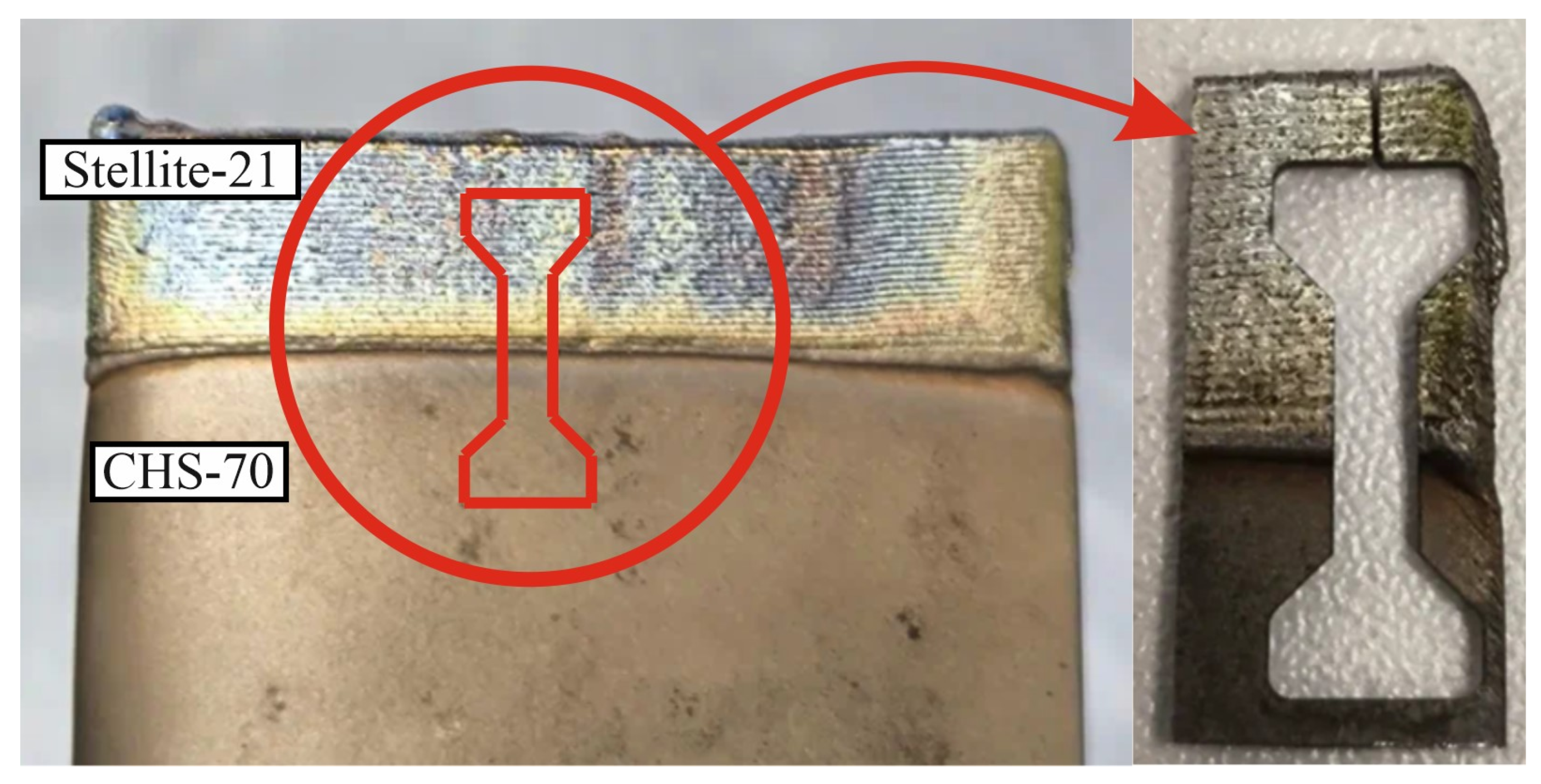
The control sample (repaired rotor blade) was subjected to a uniaxial tensile test on a Shimadzu AG 100 kNx multifunctional electro-mechanical testing unit (Shimadzu Corporation, Kyoto, Japan). The control sample microhardness was measured on a Future Tech FM-31 microhardness tester (Future-Tech Corp., Kawasaki, Japan), according to the Vickers scale. The dimensions of the projected sample are shown in Figure 7 in mm. The sample extraction sequence is shown in Figure 8.

2.7. Worn Rotor Blade Surface Cladding Approaches

2.7.1. Rotor Blade

The rotor blade end required a 0.5 mm allowance of clad metal for the subsequent machining. As the beam diameter was 1 mm, its center was aligned with the blade end upon cladding to ensure the required allowance of clad metal. The rotor blade cladding plan included a bead welding sequence, as shown in Figure 9, where the movement direction of the process tool is marked with arrows. The distance between beads ( Δ X) was 2/3 of the bead width.
The first bead was welded on the rotor blade end, as specified above, between the trailing ends. The second bead was welded from the trailing end centerline parallel to the first bead, with cladding terminating as the distance between adjacent beads decreased to the Δ X value (red spot in Figure 9), closing the second bead path. The final third bead was welded between areas left uncovered by the second bead.

2.7.2. Sealing Crest and Locking-Piece End of the Rotor Blade

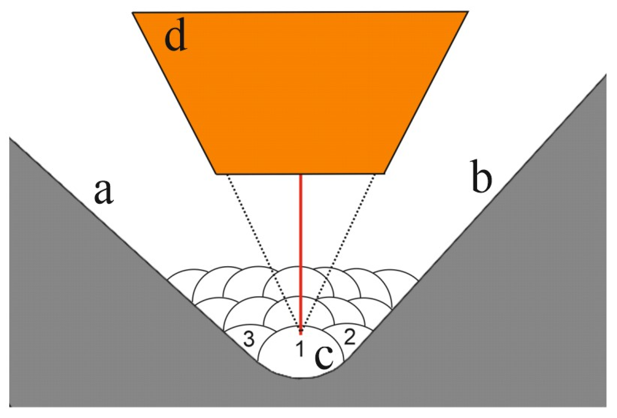
The fillet was clad prior to cladding of the sealing crests and locking-piece ends of the rotor blade, as shown in Figure 10. The bead welding sequence is given by numbers in the image, starting from the central bead, then the adjacent beads. The beads were clad in three layers.
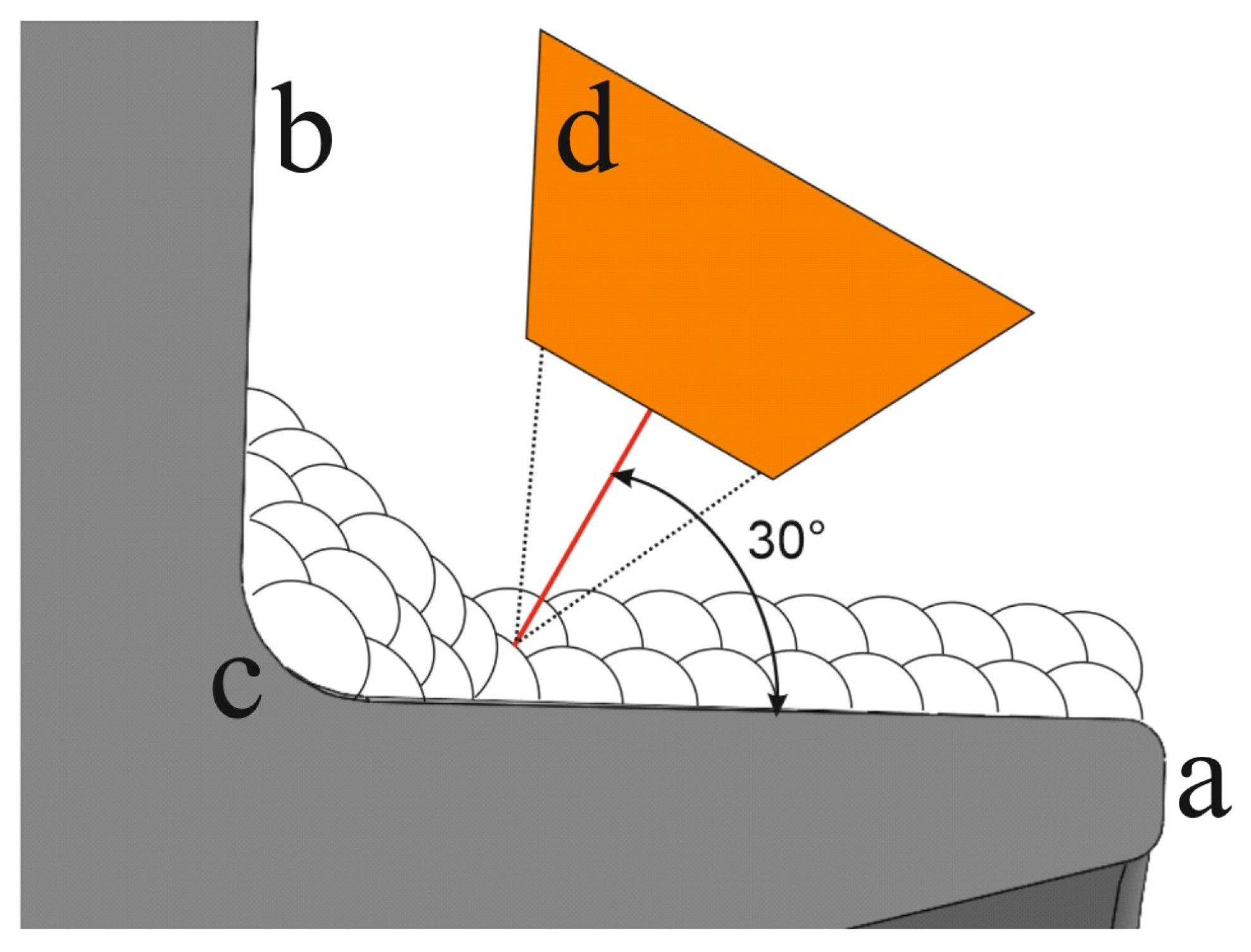
A clad fillet is required to prevent cracks upon further cladding of the sealing crest and locking-piece end, as cladding of the surfaces (a) and (b) without the fillet may result in straining of the fillet area and the corresponding cracking. Moreover, cladding of the worn surfaces (a) and (b) without the fillet may result in faulty fusion of the fillet area because of difficulties in accessing the vertically set rotor blade by the process tool due to the nozzle size and process distance from the clad surface to the process tool nozzle end (d). The locking-piece ends and sealing crests were clad after the fillet, as shown in Figure 11.
During cladding of the locking-piece end (a), the process tool (d) was set at 30°. Cladding was performed twice, from the edge of the last bead clad in the previous stage to the tip end. The sealing crest (b) was clad similarly.

3. Research Results

3.1. Results of Modeling of the Rotor Blade Cladding

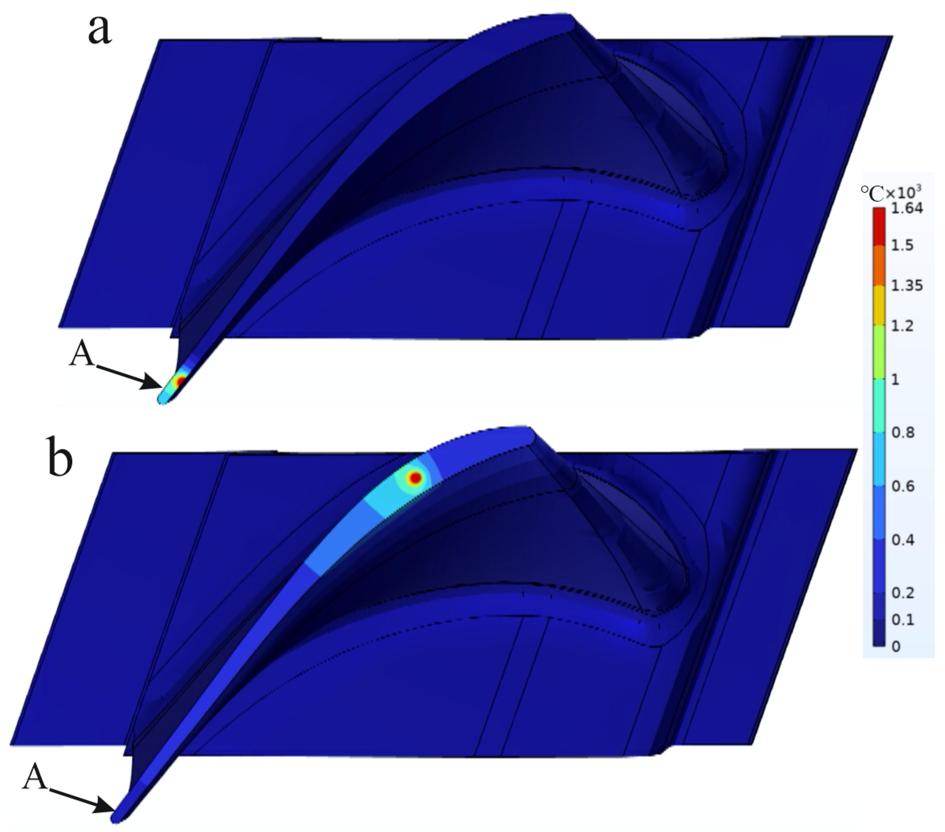
Quantitative modeling is limited to the investigation of the laser power effect on the blade temperature field at the cladding area, as the process modes No. 1, No. 4 and No. 7 have similar process parameters except for the power. The corresponding laser power was varied from 200 W to 300 W in 50 W increments, with a process tool velocity of 3 mm/s, a 1 mm beam diameter, and an additive material consumption of 2 g/min. The path of the surface heat source in the model follows the cladding plan of the rotor blade. Top views of the rotor blade cladding model at various timespans are shown in Figure 12, where point A indicates the temperature measurement location.
As mentioned above, the geometry of the rotor blade is complex, so the melt-pool size, determined by the temperature field, depends on its location on the surface of the rotor blade. Therefore, the area with the smallest thickness, corresponding to the trailing edge of the rotor blade, is the most critical, as it is the most heated area.
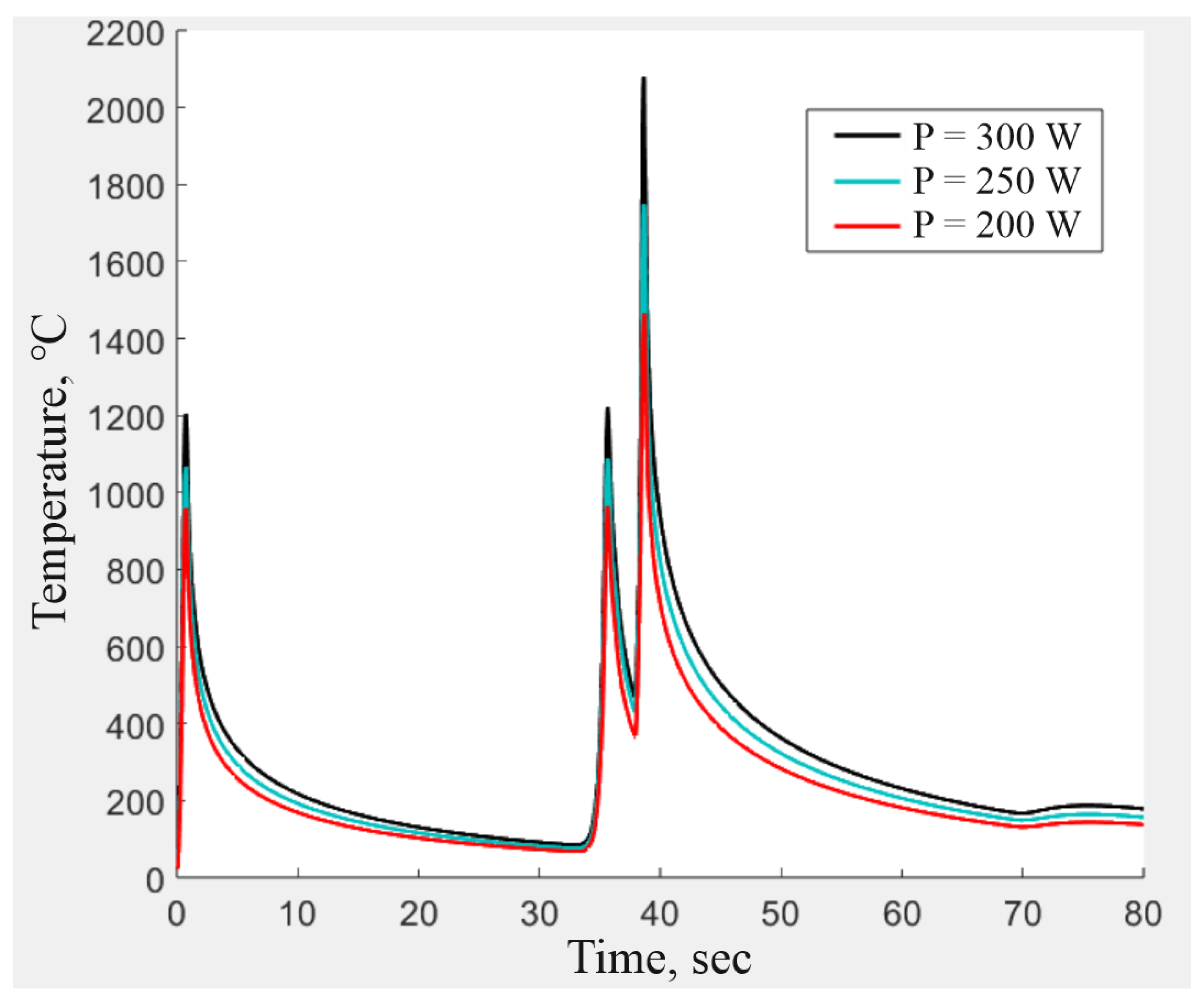
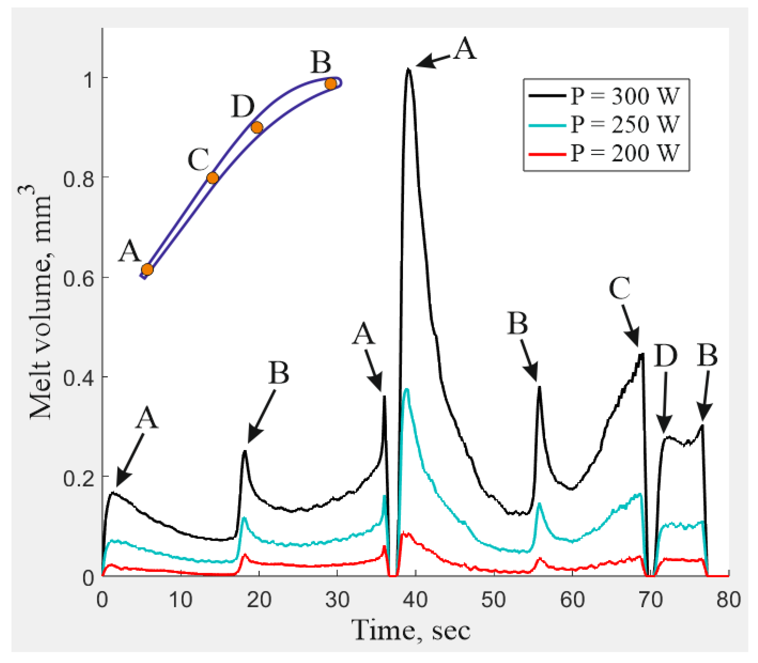
The thermal cycle plot at point A from Figure 12 and a comparison of melt-pool sizes for various laser powers during cladding are shown in Figure 13 and Figure 14, respectively.
Figure 13 shows the thermal cycle of the blade region most exposed to heat, where three temperature peaks are observed when simulating one cladding layer of the blade quill. The first peak symbolizes the beginning of the cladding from the exit edge of the feather. This is followed by a peak that corresponds to the moment when the process tool returns to the end point of the first bead at the tail of the impeller quill edge (38 s). The next peak indicates the beginning of the second bead (40 to 70 s) and then the third bead (71 s to 80 s). It is also found that the presence of a sharp increase in the volume of the melt pool is related to its geometric position on the surface of the rotor blade feather. Figure 14 shows the correspondence between the peak values of the melt pool and its position during surfacing, where each peak value corresponds to the exit (A) or entrance (B) edge of the blade feather, as well as the peripheral points of the end of the second bead (C) and the beginning of the third bead (D).
An increase in laser power resulted in an expected increase in the corresponding temperature and melt-pool size. In accordance with the quantitative analysis, the melt-pool volume at the first bead was near zero in some areas at 200 W power, which indicated faulty fusion between the additive and base materials. The maximum melt-pool volume was observed at the beginning of the second bead, when the laser beam was on the blade trailing edge, and the area remained heated after welding of the previous bead. At 300 W power, the temperature of the blade’s front surface at the trailing edge exceeded the melting temperature, producing a liquid-phase volume three times greater than the melt-pool volume at 200 W. The laser beam at 300 W power may have burned through the trailing edge of the rotor blade. In accordance with the quantitative analysis, 200 W power is insufficient due to possible faulty fusion of the base and additive materials, and 300 W power is excessive due to the enormous expansion of the molten area. So, the power determined for cladding of the rotor blade, locking-piece end, and sealing crest is 250 W, set to mode No. 4, with the corresponding process parameters provided in Table 4, where Δ Z is the height offset.

3.2. Results of Non-Destructive Testing of Control Sample

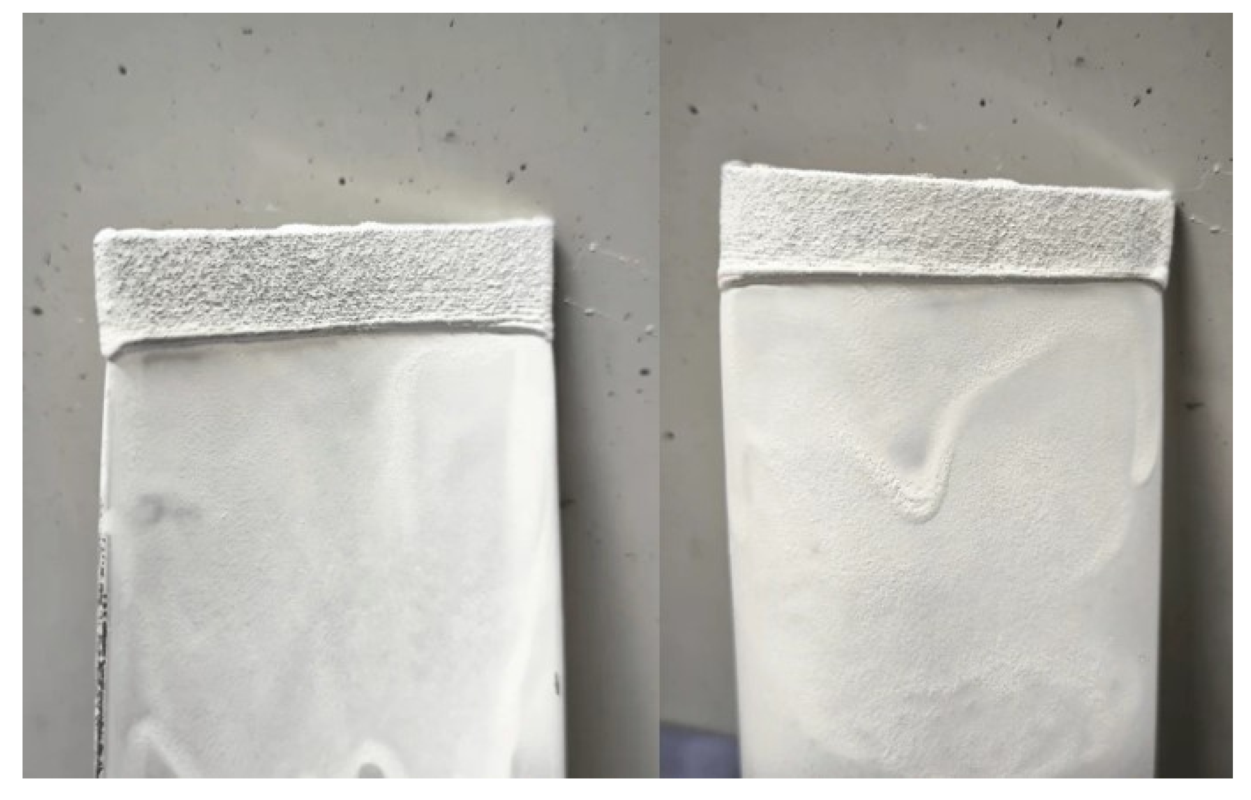
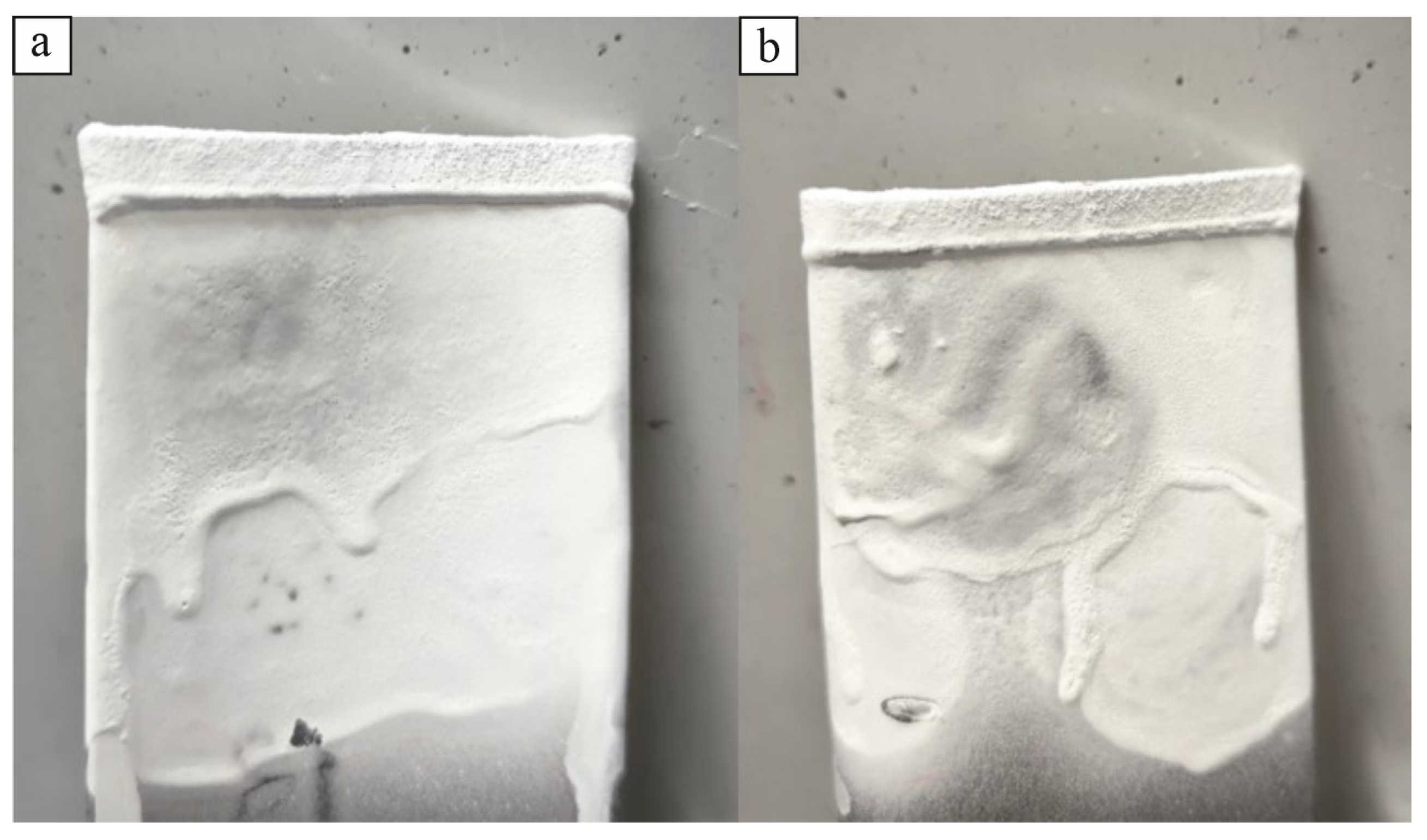
The results of liquid penetrant testing are shown in Figure 15.
After application of the penetrant, which serves as a defect indicator, white powder developer was applied. No red pigment was observed on the surface of the control sample of the repaired blade against the white developer, as shown in the figure above, so the surface was free from any defects.

3.3. Results of Macroscopic Section Analysis of Control Sample

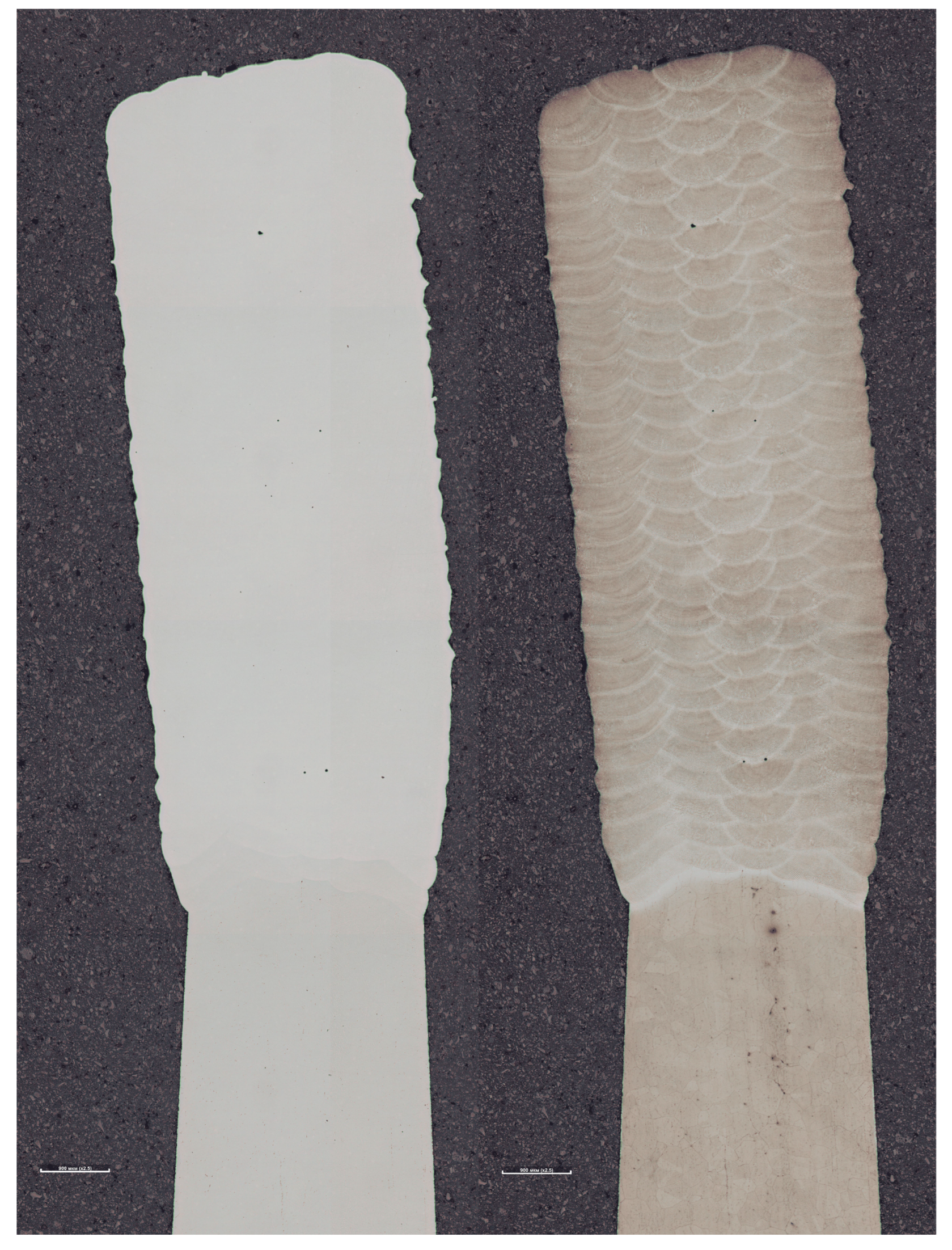
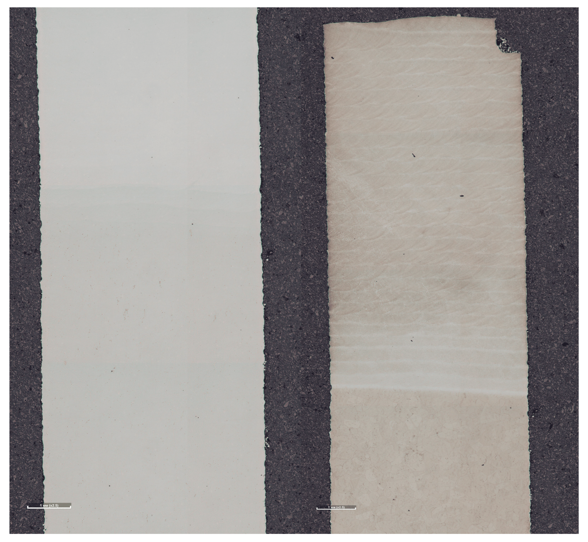
The macroscopic cross-sections and longitudinal sections of the control sample, collected during metallurgical testing, are shown in Figure 16 and Figure 17, respectively.
The internal structure of clad samples revealed no defects such as cracks or faulty fusions, as shown in Figure 16 and Figure 17. The number of isolated pores at the bead edges was within tolerable limits.

3.4. Mechanical Testing

3.4.1. Microhardness Analysis

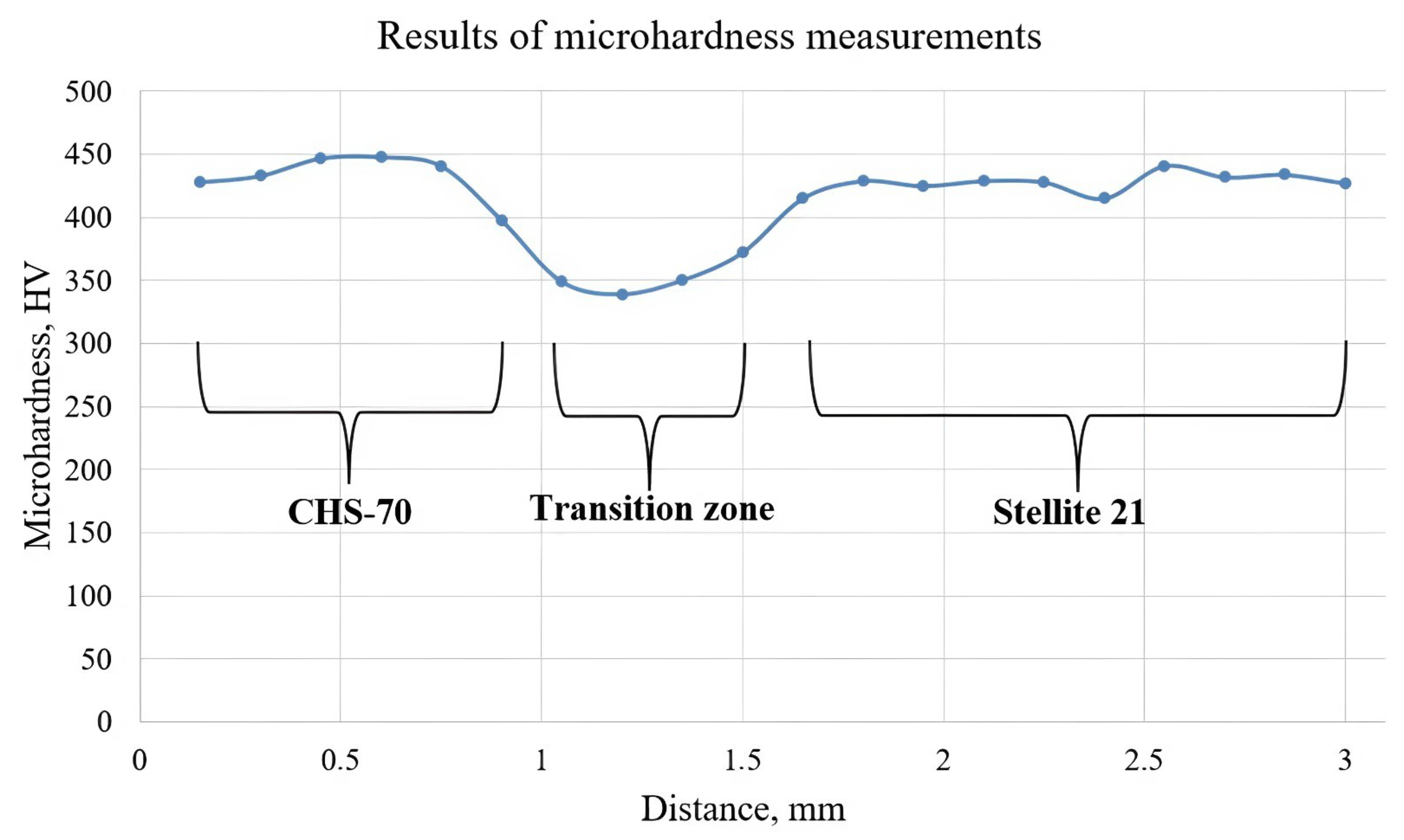
Microhardness was measured longitudinally on the samples after metallurgical testing. The measurements are provided in Table 5, and the corresponding microhardness plot is shown in Figure 18. The spacing between the control points was 150 μ m, and the measurements were taken using the Vickers method with a 300 g load.
As shown above, the microhardness of the base and filler materials was almost the same. The slight decrease in microhardness in the transition zone was due to alloy mixing and the formation of a satellite structure. The hardness of the clad layer was in the range of 415–441 HV, which corresponds to the hardened structural state.

3.4.2. Uniaxial Tension Testing

The yield, tensile strength, and relative elongation of the two specimens were determined through uniaxial tensile mechanical tests. The corresponding standard values for the alloys under investigation and the test results of two clad specimens without additional treatment are given in Table 6.
The samples fractured at the additive material zone during tension testing. The results revealed enhanced tensile strengths and appropriate relative elongations, especially for the first sample. The yield strength was comparable to that of the ChS-70 alloy manufactured using conventional methods.

3.5. Results of Rotor Blade Repair

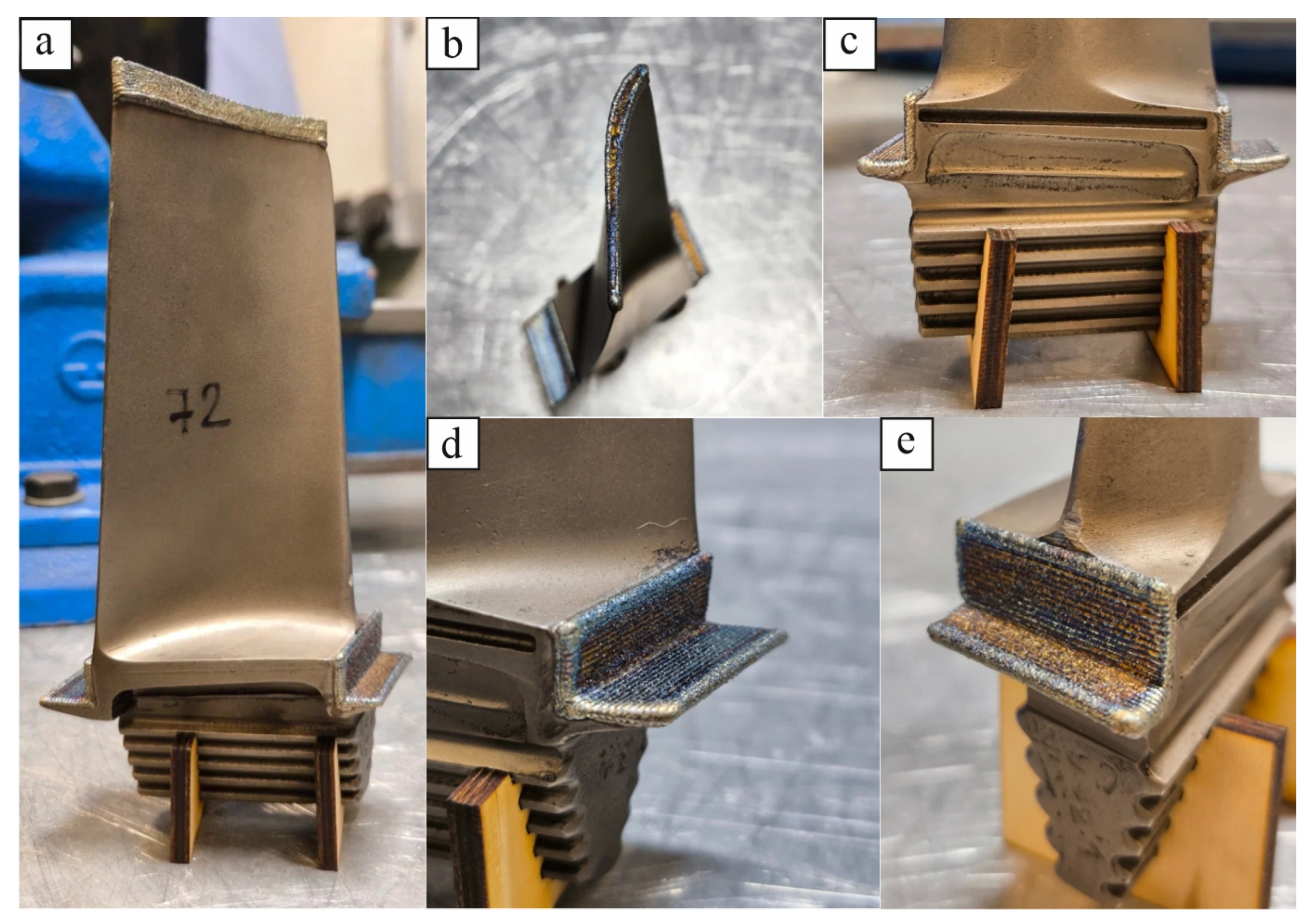
The results of rotor blade repair are shown in Figure 19.
The geometry of the repaired rotor blade was measured after the cladding of worn surfaces. The measurements showed that the dimensions of the repaired rotor blade parts corresponded to those of the rotor blade 3D model, with a 1 mm allowance for machining. The repaired rotor blade geometry measurements are provided in Table 7.

Results of Non-Destructive Testing

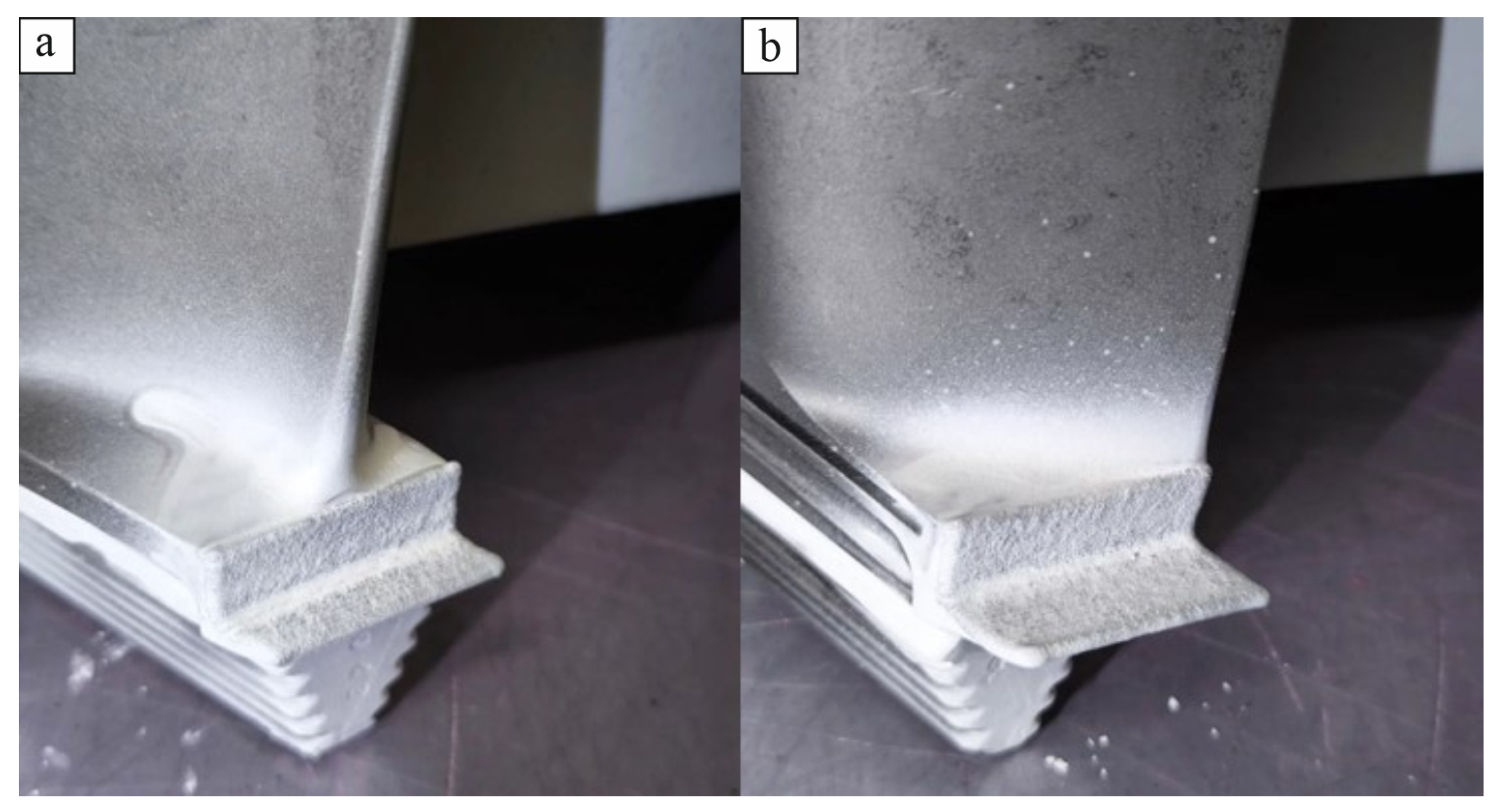
Upon visual inspection of the repaired rotor blades, no defects, such as cracks, faulty fusions, caverns, or unfused surface areas at bead couplings, were detected. Upon liquid penetrant testing, no cracks or pores were detected on the surfaces of the repaired areas. The liquid penetrant testing results are shown in Figure 20 and Figure 21.

4. Conclusions

The industrial process of repairing high-pressure rotor blades in DR-59L gas turbines using a laser cladding method was developed based on actual work.
Laser cladding process modes ensuring the absence of defects and the geometric stability of clad process samples were specified. Cladding plans for rotor blade worn surfaces, including the blade, fillets, locking-piece ends, and sealing crest, were developed. Just as in [17,18,19], positive results were obtained for surfacing the fine feather of the rotor blade, except that the base and additive materials were different, as well as the processing strategy. In addition, it is worth noting the study in [20], which used a more durable cobalt alloy to repair the turbine blade. Due to the unaccounted-for geometric parameters of the obtained beads, pores were formed during the cladding process, as noted by the authors of the study.
The repair process of the rotor blade was modeled for various laser powers to determine the cladding process mode parameters. The modeling showed that at 200 W power, the molten pool was minimal due to the power consumption by additive material melting, and at 300 W power, the temperature rose excessively and exceeded the material melting temperature, especially at the thinnest area of the blade (trailing edge), so the cladding process was performed at 250 W power.
No defects such as cracks, pores, faulty fusions, or caverns were detected on the surfaces of the repaired rotor blades after cladding the control sample. Through macroscopic section analysis, no defects of the clad material structure were detected, except isolated pores at the bead edges, in numbers within tolerable limits.
The uniaxial tensile test results showed increased tensile strength (988.5 MPa) compared to the mechanical properties of filler and base materials (724 and 900 MPa, respectively) fabricated using conventional methods.
A series of high-pressure turbine rotor blades was subjected to visual and dimensional inspection after the repair work. No defects on the surfaces of the repaired blades were detected, and the geometry of the repaired blades complied with that of the rotor blade 3D model, within a 1 mm tolerance for the repaired surfaces for machining.
Overall, the powder laser cladding method is suitable for repairing first-stage high-pressure turbine blades in DR-59L gas turbines, without the need to manufacture spare blades.

Author Contributions

Data curation, S.T. and N.R.; formal analysis, S.T., D.M. and R.M.; funding acquisition, R.K.; investigation, S.T.; methodology, S.T. and G.Z.; project administration, R.K.; resources, G.Z. and R.K.; software, D.M. and R.M.; supervision, R.K.; validation, G.Z.; writing—original draft preparation, S.T.; writing—review and editing, S.T. All authors have read and agreed to the published version of the manuscript.

Funding

This research was funded by the Ministry of Science and Higher Education of the Russian Federation under the “World-Class Science Center” program: Advanced digital technologies [grant agreement no. 075-15-2022-312, dated 20 April 2022]; and by the Russian Science Foundation under the project “Heat-Resistant Nickel Alloys for Additive Technologies: Design and Research of Structure and Properties” [project number 23-19-00622, dated 16 June 2023].

Data Availability Statement

The original contributions presented in this study are included in the article. Further inquiries can be directed to the corresponding author.

Conflicts of Interest

The authors declare no conflicts of interest. The funders had no role in the design of the study; in the collection, analyses, or interpretation of data; in the writing of the manuscript, or in the decision to publish the results.

References

  1. Toyserkani, E.; Khajepour, A.; Corbin, S.F. Laser Cladding, 1st ed.; CRC Press: Boca Raton, FL, USA, 2004; p. 280. [Google Scholar] [CrossRef]
  2. Boguslaev, V.A.; Muravchenko, F.M.; Zhemanyuk, P.D. Technological Support of Operational Characteristics of GTE Parts; OAO Motor Sich: Zaporozhye, Ukraine, 2003; pp. 6–192. [Google Scholar]
  3. Zheng, J.; Li, Z.; Chen, X. Worn area modeling for automating the repair of turbine blades. Int. J. Adv. Manuf. Technol. 2006, 29, 1062–1067. [Google Scholar] [CrossRef]
  4. Gao, J.; Folkes, J.; Yilmaz, O.; Gindy, N. Investigation of a 3D non-contact measurement based blade repair integration system. Aircr. Eng. Aerosp. Technol. 2005, 77, 34–41. [Google Scholar] [CrossRef]
  5. Richter, K.; Orban, S.; Nowotny, S. Laser cladding of the titanium alloy TI6242 to restore damaged blades. In Proceedings of the International Congress on Applications of Lasers and Electro-Optics, San Francisco, CA, USA, 4–7 October 2004; p. 1506. [Google Scholar] [CrossRef]
  6. Jones, J.; McNutt, P.; Tosi, R.; Perry, C.; Wimpenny, D. Remanufacture of turbine blades by laser cladding, machining and in-process scanning in a single machine. In Proceedings of the 23rd Annual International Solid Freeform Fabrication Symposium—An Additive Manufacturing Conference, Austin, TX, USA, 6–8 August 2012; pp. 821–827. [Google Scholar]
  7. Nicolaus, M.; Rottwinkel, B.; Alfred, I.; Möhwald, K.; Noelke, C.; Kaierle, S.; Maier, H.; Wesling, V. Future regeneration processes for high-pressure turbine blades. Ceas Aeronaut. J. 2017, 9, 85–92. [Google Scholar] [CrossRef]
  8. Henderson, M.; Arrell, D.; Larsson, R.; Heobel, M.; Marchant, G. Nickel based superalloy welding practices for industrial gas turbine applications. Sci. Technol. Weld. Join. 2004, 9, 13–21. [Google Scholar] [CrossRef]
  9. McGraw, J.; Deventer, G.; Anton, R.; Burns, A. Advancements in Gas Turbine Vane Repair. In Proceedings of the ASME 2006 Power Conference, Atlanta, GA, USA, 2–4 May 2006. [Google Scholar] [CrossRef]
  10. Wilson, J.; Piya, C.; Shin, Y.; Zhao, F.; Ramani, K. Remanufacturing of turbine blades by laser direct deposition with its energy and environmental impact analysis. J. Clean. Prod. 2014, 80, 170–178. [Google Scholar] [CrossRef]
  11. Bi, G.; Gasser, A. Restoration of Nickel-Base Turbine Blade Knife-Edges with Controlled Laser Aided Additive Manufacturing. Phys. Procedia 2011, 12, 402–409. [Google Scholar] [CrossRef]
  12. Rottwinkel, B.; Noelke, C.; Kaierle, S.; Wesling, V. Laser Cladding for Crack Repair of CMSX-4 Single-Crystalline Turbine Parts. Lasers Manuf. Mater. Process. 2017, 4, 13–23. [Google Scholar] [CrossRef]
  13. Kelbassa, I.; Gasser, A.; Wissenbach, K. Laser cladding as a repair technique for BLISKs out of titanium and nickel base alloys used in aero engines. In Proceedings of the Pacific International Conference on Applications of Lasers and Optics, Melbourne, Australia, 19–21 April 2004; Volume 503. [Google Scholar] [CrossRef]
  14. Sorokin, L.I. Argon-arc cladding of blade blade flanges made of high-temperature nickel alloys. Weld. Prod. 2004, 7, 36–39. [Google Scholar]
  15. Smyslov, A.M.; Smyslova, M.K.; Selivanov, K.S.; Mingazhev, A.D. Method of Repair of Gas Turbine Blades Made of Nickel and Cobalt Alloys. Patent 2346075; Russian Federation, MPC C22F 1/10. 2009, 2006116330/02 p. 8, Available online: https://patents.google.com/patent/RU2346075C2/ru (accessed on 26 August 2025).
  16. Lowden, P.; Pilcher, C.; Liberdi, J. Integrated Weld Automation for Gas Turbine Blades. In Proceedings of the ASME 1991 International Gas Turbine and Aeroengine Congress and Exposition, Orlando, FL, USA, 3–6 June 1991. 7p. [Google Scholar]
  17. Chen, C.; Wu, H.; Chiang, M. Laser cladding in repair of IN738 turbine blades. Int. Heat Treat. Surf. Eng. 2008, 2, 140–146. [Google Scholar] [CrossRef]
  18. Uenal, T.; Gahn, L.; Kittel, J.; Gasser, A.; Schleifenbaum, J. Process Development for Tip Repair of Complex Shaped Turbine Blades with IN718. Procedia Manuf. 2020, 47, 1050–1057. [Google Scholar] [CrossRef]
  19. León-Henao, H.; Herderick, E.; Toro, A.; Giraldo-Barrada, J.; Ramirez, A. Assessing the Printability of Rene 65 Powder for Repairing Degraded GTD 111 Gas Turbine Blades Using L-DED and L-PBF. Coatings 2025, 15, 410. [Google Scholar] [CrossRef]
  20. Brandt, M.; Sun, S.; Alam, N.; Bendeich, P.; Bishop, A. Laser cladding repair of turbine blades in power plants: From research to commercialisation. Int. Heat Treat. Surf. Eng. 2009, 3, 105–114. [Google Scholar] [CrossRef]
  21. John, C. Chapter 12—Cladding. In Laser Processing of Engineering Materials; Elsevier: Amsterdam, The Netherlands, 2007; pp. 296–326. [Google Scholar]
  22. Carslaw, H.S.; Jaeger, J.C. Conductionof Heat in Solids; Clarendon Press: Oxford, UK, 1959; p. 510. [Google Scholar]
  23. ISO 3452-2:2009; Non-Destructive Testing. Penetrant Testing. Part 2. Testing of Penetrant Materials. Standartinform: Moscow, Russia, 2009.
  24. ISO 13919-1-2017; Welding. Electron and Laser-Beam Welded Joints. Guidance on Quality Levels for Imperfections. Part 1. Steel. Standartinform: Moscow, Russia, 2017.
  25. Berdnik, O.B. Development of Resource-Saving Remanufacturing Technology for High-Pressure Turbine Blades Made of Heat-Resistant Nickel Alloys. Prometey 2009. Available online: https://rusneb.ru/catalog/000199_000009_003461857/ (accessed on 26 August 2025).
  26. Available online: https://www.matweb.com/ (accessed on 18 July 2025).
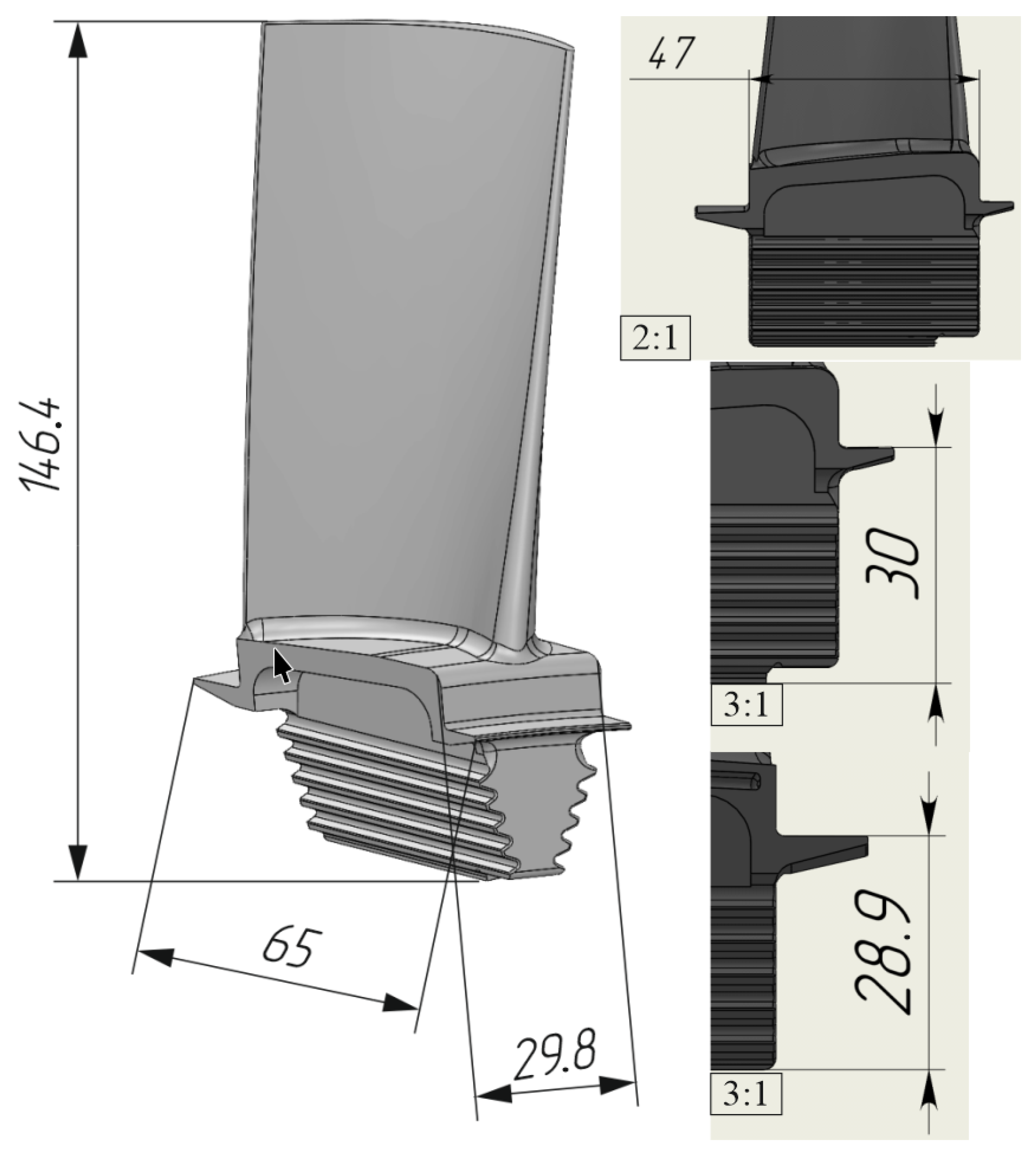
Figure 1. Rotor blade dimensions.
Metals 15 00957 g001
Figure 2. Three-dimensional model of the rotor blade showing the worn areas: 1(a) locking-piece end at 11 mm; 1(b) locking-piece end at 7 mm; 2 sealing crest; 3 blade.
Metals 15 00957 g002
Figure 3. Morphology of Stellite 21 powder particles: (a) Magnification at 500 μ m; (b) Magnification at 200 μ m.
Metals 15 00957 g003
Figure 4. ILWT-M unit for direct laser deposition: (A) Installation ILWT-M; (B) Process tool (a) powder supply nozzle (b) adjustment unit (c) optical welding head (IPG FLW D30L).
Metals 15 00957 g004
Figure 5. Visual appearance of the clad process sample.
Metals 15 00957 g005
Figure 6. Cross-sections: No. 1–No. 5, No. 7 The numbers of the samples obtained according to the table “Modes of laser cladding”, where samples with defects are indicated in red, without defects in green of process samples.
Metals 15 00957 g006
Figure 7. Dimensions of projected sample.
Metals 15 00957 g007
Figure 8. Sequence of sample extraction for mechanical testing.
Metals 15 00957 g008
Figure 9. Rotor blade cladding plan.
Metals 15 00957 g009
Figure 10. Fillet cladding plan: 1 first bead, 2 second bead, 3 third bead, (a) locking-piece end, (b) sealing crest, (c) fillet, (d) process tool.
Metals 15 00957 g010
Figure 11. Locking-piece end cladding plan: (a) locking-piece end, (b) sealing crest, (c) fillet, (d) process tool.
Metals 15 00957 g011
Figure 12. Rotor blade cladding model (top views) at 300 W power: (a) cladding timespan 2 s, (b) cladding timespan 73 s, A thermocouple location.
Metals 15 00957 g012
Figure 13. Thermal cycle plot at point A for various laser powers.
Metals 15 00957 g013
Figure 14. Melt-pool volume at various laser powers, the blue line highlights the sketch of the blade’s feather in the top view: A outlet edge point of the impeller blade feather, B inlet edge point of the rotor blade feather, C end point of the second bead, D starting point of the third bead.
Metals 15 00957 g014
Figure 15. Results of liquid penetrant testing.
Metals 15 00957 g015
Figure 16. Cross-sections of the control sample prior to (left) and after (right) pickling.
Metals 15 00957 g016
Figure 17. Longitudinal sections of the control sample prior to (left) and after (right) pickling.
Metals 15 00957 g017
Figure 18. Microhardness plot.
Metals 15 00957 g018
Figure 19. Appearance of repaired rotor blades: (a) general view of the rotor blade; (b) feather of the rotor blade, top view; (c) locking-piece end and sealing crest, rear view; (d) locking-piece end at 11 mm and sealing crest; (e) locking-piece end at 7 mm and sealing crest.
Metals 15 00957 g019
Figure 20. Results of rotor blade liquid penetrant testing: (a) rotor blade, front view; (b) rotor blade, rear view.
Metals 15 00957 g020
Figure 21. Results of rotor blade locking-piece end and sealing crest liquid penetrant testing: (a) locking-piece end at 7 mm and sealing crest; (b) locking-piece end at 11 mm and sealing crest.
Metals 15 00957 g021
Table 1. Chemical composition of the ChS-70 alloy.
Alloy GradeElement Content, % Mass
NiCoAlTiMoWCCrNb
ChS-70The rest10.52.84.62.05.00.0815.50.3
Table 2. Chemical composition of the Stellite 21 alloy.
Alloy GradeElement Content, % Mass
NiCoFeMoCCrSi
Stellite 213.0The rest1.55.50.2527.01.0
Table 3. Modes of laser cladding.
No.Parameters
Power (P), WVelocity (V), mm/sPowder Consumption (G), g/minBeam Diameter (D), mmTransportation Gas Flow Rate, L/min
12003214
220042.5
320053
425032
525043.5
625054
730032
830044.5
930055
1035032
1135045.5
1235056
1340032
1440046.5
1540057
Table 4. Process parameters of rotor blade cladding.
P, WV, mm/sG, g/min Δ X , mm Δ Z , mmD, mm
250320.660.41
Table 5. Microhardness measurements.
AlloyMeasurement No., Microhardness in HV
12345678910
ChS-70428433447448441398349339350372
Stellite 21415429425429428415441432434427
Table 6. Mechanical properties of Stellite 21, ChS-70 alloys [25,26], and samples.
Alloy/SampleYield Strength, σ 0.2 , MPaRelative Elongation, δ , %Tensile Strength, σ U , MPa
ChS-707503.0900
Stellite 215509.0724
16926.7995
27434.5982
Average value for samples717.55.6988.5
Standard deviation for samples361.69.2
Table 7. Repaired rotor blade geometry measurements.
PartBlade, mmLocking Piece (a), mmLocking Piece (b), mmSealing Crest, mm
Value147.5–14830–30.431.1–31.548.1–48.5
Disclaimer/Publisher’s Note: The statements, opinions and data contained in all publications are solely those of the individual author(s) and contributor(s) and not of MDPI and/or the editor(s). MDPI and/or the editor(s) disclaim responsibility for any injury to people or property resulting from any ideas, methods, instructions or products referred to in the content.