Article

Arc Quenching Effects on the Groove Shapes of Carbon Steel Tubes

Faculty of Mechanical Engineering, HCMC University of Technology and Education, Ho Chi Minh City 71307, Vietnam
*
Author to whom correspondence should be addressed.
Metals 2025, 15(9), 928; https://doi.org/10.3390/met15090928
Submission received: 13 July 2025 / Revised: 17 August 2025 / Accepted: 20 August 2025 / Published: 22 August 2025

Abstract

This study investigates the impact of arc-hardening parameters on a groove-shaped S45C steel tube, with a focus on surface hardness and microstructure. According to the findings, when arc quenching occurs, the tube’s surface hardness increases significantly compared to its original hardness. The surface layer hardness can increase to 50.3 HRC, which is 3.4 times greater than the untreated surface. Changing arc quenching parameters such as current intensity, gas flow rate, arc length, scan speed, heating angle, and cooling angle causes a variation in surface hardness due to the balance of heat input and cooling value. Moreover, the microhardness distribution is divided into three zones: the hardened zone (with a high hardness value), the heat-affected zone (HAZ), which has rapidly declining hardness, and the base metal (with a low hardness value). The hardened zone could have a hardness with a load of 0.3 N of 440 HV and a case depth of about 900 μm. The next zone is the HAZ, where the hardness with a load of 0.3 N drops significantly. The hardness in the base metal zone recovers to its original value of 152 HV. Interestingly, the microstructure, under the hardness distribution, illustrates the relationship between the hardness value and its phases. The hardened zone consists of martensite and residual austenite phases, resulting in a high hardness value. The bainite phase constitutes the HAZ, which correlates to the zone of rapid hardness reduction. Finally, the base metal zone has ferrite and pearlite microstructures, indicating the softest zone. The investigation’s findings may increase our understanding of the arc-hardening process and widen its industrial applications.

1. Introduction

During the working process, many mechanical parts could suffer complex conditions, such as high loading, wear, corrosion, and high impact. They may experience different treatment processes to achieve these working conditions, for example, high hardness on the surface under surface quenching and high impact of the core [1,2,3]. Recently, local heat treatment operations appear to be more attractive, as they could control the microstructure of small areas with tiny case hardening depth, fitting many integrational requirements. Therefore, the local hardening techniques such as induction quenching, laser quenching, electron beam quenching, and flame quenching are widely applied [4,5,6,7,8,9,10]. Interestingly, the local hardening techniques have the advantage of self-quenching due to the natural cooling of the matrix around the localized heat-treated areas rather than requiring a strong cooling agent [11,12,13]. Therefore, the need for a further quenching medium step using oil, water, or compressed air is minor.
Arc quenching applied a high-intensity electric arc to heat the steel surface to an elevated temperature [14]. After heating, the heated component is cooled down by a suitable quenching medium, leading to the formation of advanced microstructures with high-hardness value. Therefore, with the formation of a thin hardened layer, the wear resistance is strongly improved while the toughness of the core is still preserved. The arc quenching method can be precisely controlled with high efficiency; therefore, it could have good potential in the manufacturing and automotive industries. There are many reports investigating the arc quenching method.
For example, Dombrovskii et al. [15] modified the steel surface by air-plasma arc with the assistance of a scanning device. They proved that with the application of plasma arc quenching on, the case hardening depth of 2.5 mm could be achieved. Nguyen et al. [16] focused on the self-quenching ability of the arc quenching process to improve the surface hardness of the S45C steel. The process parameters, such as current intensity, arc length, travel speed, and gas flow rate, are optimized to achieve good surface hardness. The current intensity appears to be the most critical factor that impacts the surface hardness value. Moreover, the original ferrite and pearlite structures are transformed to the super-saturated martensite structure with high-hardness and wear-resistance characteristics. Arai et al. [17] revealed a hardening effect during the vacuum arc cleaning (VAC) of the oxide layer. The oxide layer is heated dramatically when the cathode spots on the original surface, leading to its evaporation. The heated surface is also hardened due to the rapid heating of the arc energy. Compared to the original surface, the hardness value can rise up to two or three times. The study also indicated that increasing the VAC treatment time gives rise to the hardening case depth. Due to the high self-cooling rate, the surface hardness is enhanced by the formation of martensite structure. The VAC technique provides the potential of both cleaning and hardening the surface in the same process.
Safonov et al. [18] reported on the arc hardening of low-carbon steel. The arc-treated surface forms a thin layer of martensite–austenite structure, while the heat-affected zone has the structure of ferrite–austenite structure. Repeated heating at the same area leads to the reduction of martensite microstructure as it is tempered and therefore transforms to bainite and sorbite structure. However, the austenite ratio is improved as the surface is reheated. Overall, the surface hardness and case depth can be controlled by arc current and travel speed. Nikolaou et al. [19] investigated the case hardening technique using the plasma transferred arc (PTA) alloying process for plain carbon steel. This technique can be controlled to achieve carburizing or case hardening, depending on the operation parameters. After treatment, the surface hardness is greatly improved.
Mikheev et al. [20] applied arc quenching to improve the hardness of medium-carbon and high-carbon steels. Besides different steel grades, they also survey the impact of arc current and travel speed. The microhardness could increase up to 4–5 times compared to the original surface. The case depth after arc quenching could be 300–500 μm, depending on the steel types, arc current, and travel speed. With medium carbon steel, the wear resistance was four times better than the original surface.
More than that, Dewangan et al. [21] welded four AISI 1020 samples using metal arc. One sample was kept after welding, while the other three were heat-treated using three distinct techniques: steel annealing, water quenching, and oil quenching. The hardness of the samples was then tested after quenching. As the hardness increased from 73.2 HRB to 77 HRB for water quenching and 76 HRB for oil quenching (improved about 5% hardness), the results indicated that heat treatment in the weld zone (molten metal zone) only slightly increased the hardness. This can demonstrate that quenching after the welding arc is completed does not considerably enhance the weld’s quality. Therefore, electric arc quenching is a very effective method to improve the surface hardness of S45C steel with the same efficiency as other more expensive quenching methods.
Besides the arc current and travel speed, the arc angle, cooling angle, and surface condition could affect the arc hardening process. However, these factors are rarely discussed. This study investigated the influence of arc quenching process parameters of grooved carbon steel by examining the arc current using a tungsten internal gas (TIG) welding machine, travel speed, arc angle, cooling angle, and surface condition. The investigation’s findings could improve our comprehension of this arc-hardening technique and broaden its industry practicality.

2. Experimental Methods

The groove shape is created on an S45C carbon steel tube, with a diameter of 79 mm, thickness of 5.0 mm, and length of 500 mm, as shown in Figure 1. The groove size on the tube is 1.0 mm in depth and 3.0 mm in width. The composition of the S45C part is shown in Table 1. The arc source is generated via a TIG welding machine (TIG200 W223, JASIC Company, Shenzhen, China), fixed on a CNC machine (The main equipment of the CNC machine is assembled from different places, such as: three-jaw self-centring chucks of SAN OU Company, Taizhou, China; 23KM Series Stepper Motors of MinebeaMitsumi, Nagano, Japan; PLC FX3U-32MT-6AD-2DA of Mitsubishi, Himeji, Japan; the remaining auxiliary equipment is manufactured in Ho Chi Minh City, Vietnam).
According to the study of Kumar et al. [22], the heat input used to heat the steel surface is calculated according to Equation (1).
H e a t   i n p u t = µ   . I . U S c a n   s p e e d   ( k J / m m )
where
µ is the efficiency of the surface quenching process. This efficiency is based on the general parameters of arc length, gas flow rate, and other influencing factors.
U is the voltage of electricity; the unit is volts.
I is the current intensity; the unit is ampe.
Scan speed is the relative speed of movement between the TIG tip and the steel surface; the unit is mm/min.
Therefore, this study examines the current intensity, gas flow rate, arc length, travel speed, heating angle, and cooling angle. Therefore, this study examines the current intensity, gas flow rate, arc length, travel speed, heating angle, and cooling angle. In which current intensity is a very important parameter in the arc generation process [22,23], so this study will conduct a survey of five different current intensity levels, including 120A, 125A, 130A, 135A, and 140A. This is the same current intensity range as the study by Kumar et al. [22], but it has a survey range of 5A, which is shorter than 20A. Scanning speed is a parameter that affects the heating process for the surface [22,23]. When the scanning speed increases, the heat reception time of the surface is shortened, so the amount of heat received from the TIG head will be lower [22,23]. The study will be carried out at 5 different levels, including 460 mm/min, 470 mm/min, 480 mm/min, 490 mm/min, and 500 mm/min; this is the survey range with the highest depth of hardened layer according to the study of Mikheev et al. [20]. With arc length, this is a parameter that affects the arc creation process as well as the heat transfer process to the surface of the part. If it is too short, the arc will not occur or will stick to the part; if it is too long, the electric arc will not occur. According to Nguyen et al. [16], the range from 1.0 mm to 2.0 mm will have a large influence on the surface hardness after quenching; therefore, this study will perform 5 levels with specific parameters of 1.1 mm, 1.3 mm, 1.5 mm, 1.7 mm, and 1.9 mm. In addition to its protective effect, the gas flow rate also supports the rapid cooling of the surface after quenching. Therefore, the study also evaluated this parameter at 5 levels: 8 L/min, 10 L/min, 12 L/min, 14 L/min, and 16 L/min. The remaining two parameters are the heating angle and the cooling angle, as shown in Figure 2. In which the heating angle shapes the temperature profile and is studied at the parameter levels of 70°, 80°, 90°, 100°, and 110°. Meanwhile, the cooling angle represents the angular distance from the TIG head position to the cooling water nozzle supporting the quenching process to create the martensite phase. If the cooling angle is large, the distance will be further, and the cooling process will not be very meaningful; if the cooling angle is small, the water spray process will affect the surface quenching process because water may attack the TIG head, affecting the heating process. Therefore, the study will be carried out at 5 levels of 70°, 80°, 90°, 100°, and 110°. All process parameters are shown in Table 2. The voltage is fixed at 80 V, and the coolant is water at 30 °C.
The surface hardness is measured using an HR-150A Rockwell hardness tester, Yisite, Shen Zhen, China. A microscope named Oxion OX.2153-PLM EUROMEX, Duiven, The Netherlands, is used to observe the microstructure of the samples.

3. Results and Discussion

3.1. Effects of Arc Hardening Parameters on the Surface Hardness

Figure 3 shows the influence of current intensity on the hardness of the S45C steel tube with a groove shape. The surface hardness values are 43.7 HRC, 44.8 HRC, 41.1 HRC, 50.3 HRC, and 39.5 HRC, corresponding to the current intensity of 120A, 125A, 130A, 135A, and 140A. Increases in the current intensity lead to a fluctuation in the surface hardness. Moreover, the reduction of the 140A sample could be due to the overheating phenomenon, which is similar to the Patel et al. [24] study. The higher current intensity could lead to higher heat input, leading to the surface being molten and reducing its hardness. It is noteworthy that compared to the original hardness of the tube, which is only 154 HB or 152 HV, the surface hardness increases dramatically. The hardness could increase up to the maximum value of 50.3 HRC or 515 HV at the current intensity of 135A, which is 3.4 times higher than the original one. Overall, after the arc hardening process, the surface hardness improves from 2.5 to 3.4 times, indicating the advantage of the rapid hardening process of arc quenching.
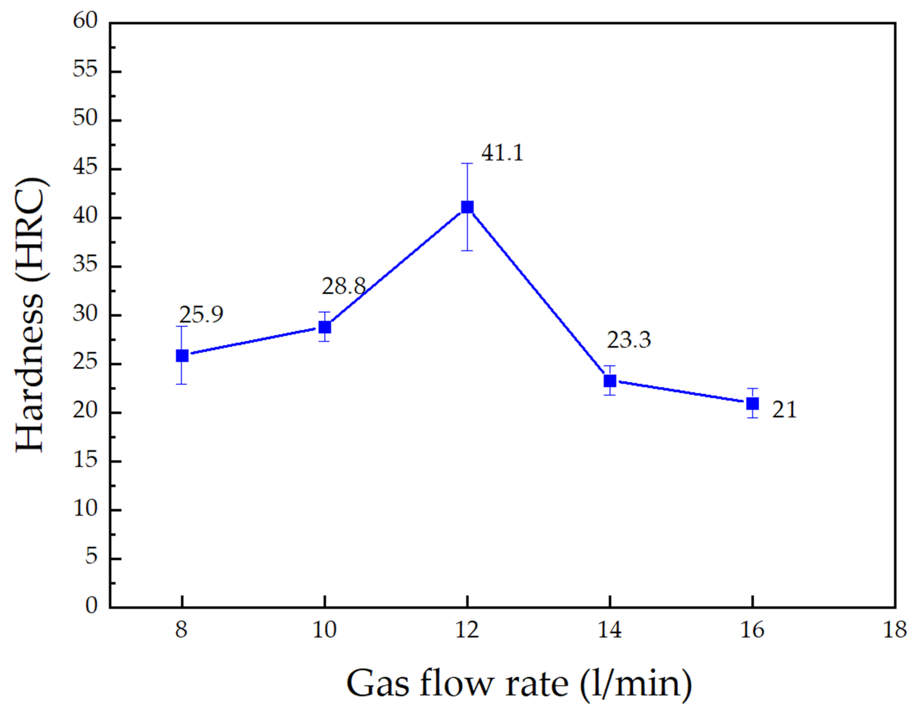
Figure 4 presents the influence of gas flow rate on the hardness of the S45C steel tube with a groove shape. The changing pattern of the gas flow rate vs. hardness is simpler than the current intensity one. Initially, increasing the gas flow rate from 8 to 12 L/min results in an improvement in the surface hardness from 25.9 HRC to the highest value of 41.1 HRC. At 12 L/min, the arc is more stable; therefore, the surface hardness reaches its highest value. Jeyaprakash et al. [25] also proved that the arc generation process requires a stable gas flow rate to be suitable for heating. Thereafter, a further increase from 12 L/min to 16 L/min leads to a great reduction from 41.1 HRC to 21 HRC. In general, the optimal gas flow rate value for the highest surface hardness is 12 L/min.
The influence of arc length on the hardness of the S45C steel tube with a groove shape is shown in Figure 5. From 1.1 mm to 1.5 mm arc length, the surface hardness improves from 31.1 HRC to 41.1 HRC when the arc length increases due to the better heat distribution, reducing the possibility of melting phenomenon. However, from 1.5 mm to 1.9 mm, the surface drops to 18.3 HRC and 26.9 HRC, which is due to the poor heat flux distribution of the arc on the groove shape. Zhang et al. [26] suggested that the arc length strongly impacts the heat flux distribution; therefore, a suitable arc length could give rise to the hardening process. Generally, the optimal arc length is 1.5 mm, leading to an improvement of 2.7 times compared to the original surface.
Besides the current intensity, gas flow rate, and arc length, this study also investigates the impact of scan speed on the hardness of the S45C steel tube with a groove shape, as shown in Figure 6. Interestingly, the hardness changing pattern in Figure 6 is similar to Figure 4, having a mountain-peak shape. Kumar et al. [22] report indicated that the scan speed could impact the heat flux input; therefore, it strongly impacts the phase transformation process and the surface hardness. When increasing the scan speed, the heat input level reduces. In this case, increases in the scan speed from 460 mm/min to 480 mm/min lead to an increase in the surface hardness from 35.3 HRC to 41.1 HRC due to the better heating temperature for martensite phase transformation. After that, the surface hardness reduces from 41.1 HRC to 35.5 HRC when further increasing the scan speed from 480 mm/min to 500 mm/min, which could be due to the less heat input, reducing the suitable condition for martensite phase transformation. The optimal scan speed is revealed at 480 mm/min.
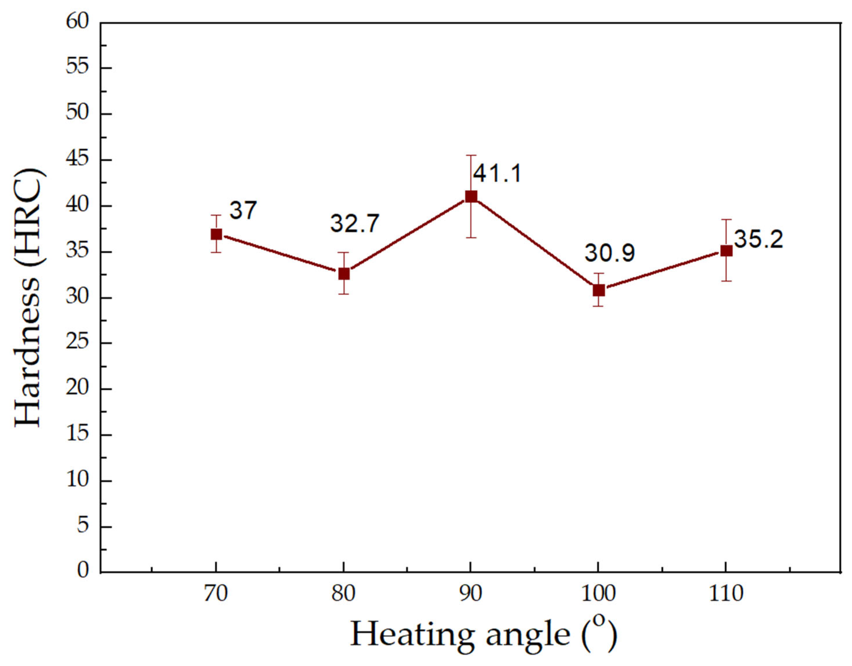
During the arc hardening process, changing the heating angle could lead to a variation in heat flux distribution; therefore, the surface hardness could be impacted. Figure 7 shows the influence of the heating angle on the hardness of the S45C steel tube with a groove shape. The surface hardness values are 37 HRC, 32.7 HRC, 41.1 HRC, 30.9 HRC, and 35.2 HRC, corresponding to the heating angles of 70°, 80°, 90°, 100°, and 110°. Notably, similar to the influence of current intensity, changing the heating angle in the range of 70–110° results in the fluctuation of the surface hardness. At 90°, the hardened sample reaches its highest hardness of 41.1 HRC. Furthermore, the cooling angle could also affect the surface hardness of the arc-hardening sample and is investigated in the following result.
The cooling angle is the angle between the direction of the TIG head and the direction of the cooling water nozzle. Similar to the heating angle, the angle of water cooling might affect the arc hardening quality. The influence of the cooling angle on the hardness of the S45C steel tube with a groove shape is presented in Figure 8. The surface hardness values are 30.2 HRC, 36.3 HRC, 41.1 HRC, 36 HRC, and 38.1 HRC, corresponding to the cooling angles of 70°, 80°, 90°, 100°, and 110°. The surface hardness increases with the increase in the cooling angle from 70° to 90°. After that, the effect of the cooling angle fluctuates without a clear trend. This can be explained by the fact that after a period of rapid cooling, the surface temperature has decreased significantly, so the cooling process at a distance quite far from the TIG head is no longer obvious. and the hardened sample obtained the highest hardness of 41.1 HRC at the cooling angle of 90°. Besides the surface hardness, the microhardness through the case hardening depth and the microstructure of the arc hardening samples are also examined in the next figures.

3.2. Hardness with Load and Microstructure of the Hardened Sample

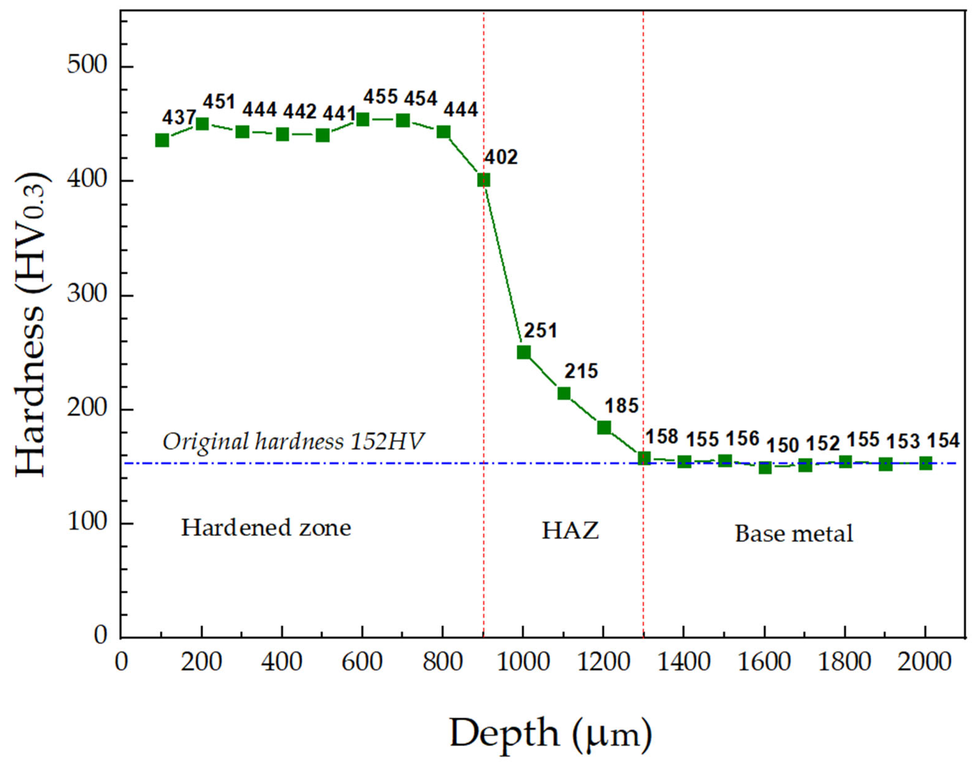
Figure 9 presents the hardness with a load of 0.3 N vs. depth of sample No. 3. after the arc hardening process. There are 3 zones in the diagram, including the hardened zone with a high-hardness value, the heat-affected zone (HAZ) with rapidly reducing hardness, and base metal with a low-hardness value. In the hardened zone, the hardness with a load of 0.3 N varies around 440 HV, which is 2.9 times higher than the original hardness. The hardened zone reaches the case depth of 900 μm, which is comparable to the electron beam and laser hardening methods [6,10]. The next zone is the HAZ, where the hardness with load of 0.3 N reduces dramatically from 402 HV to 158 HV. This HAZ has a depth value from 900 μm to 1300 μm, which is equal to 400 μm depth. Finally, in the base metal zone, from 1300 μm depth, the hardness tends to come back to the original value of 152 HV. To explain these results, the microstructure of these zones is shown in Figure 10.
Figure 10 shows the structure of sample No. 3 after arc quenching. The heat input spreads toward the hardened metals in the double ellipsoidal density distribution shapes due to the ellipsoidal heat source, which is consistent with Nguyen et al. [23] report. Depending on the heat intensity, the microstructure of the base metal is transformed at different rates. Therefore, the microstructure of the hardened sample can be distinguished into three zones, including the hardened zone at the top surface, the HAZ, and the base metal zone. This microstructure distribution is consistent with the hardness with load of 0.3 N distribution mentioned in Figure 9. This result also helps explain the reason for the difference in the hardness with the load 0.3 N of the sample when measuring at different case depths. The hardened zone comprises martensite and residual austenite phases [14,18,20], correlated with the high-hardness value. The HAZ consists of the bainite phase, corresponding to the rapid hardness reduction zone. Finally, the base metal region has a ferrite and pearlite microstructure, corresponding to the softest zone.

4. Conclusions

This study analyzes the effects of arc-hardening parameters on the groove-shaped S45C steel tube, focusing on the surface hardness and microstructure. Some interesting findings that could be disclosed include the following:
-
Compared to the original hardness of the tube, the surface hardness increases dramatically when applying arc quenching. The surface hardness can rise to 50.3 HRC, which is 3.4 times higher than the untreated surface. Changing the arc quenching parameters, such as current intensity, gas flow, arc length, scanning speed, heating angle, and cooling angle, leads to fluctuations in surface hardness because these parameters directly affect the surface heating and rapid cooling of S45C steel.
-
The hardness with load distribution contains three zones: the hardened zone with a high hardness value, the heat-affected zone (HAZ) with rapidly falling hardness, and the base metal with a low hardness value. The hardened zone has a hardness with a load of 0.3 N of around 440 HV and a case depth of approximately 900 μm. The next zone is the HAZ, where the hardness with a load of 0.3 N decreases drastically. In the base metal zone, the hardness constantly returns to its initial value of 152 HV.
-
The microstructure, consistent with the hardness distribution, reveals the relationship between the hardness value and its phases. The hardened zone consists of martensite and residual austenite phases, which correspond to a high hardness value. The bainite phase makes up the HAZ, which corresponds to the zone of rapid hardness decline. Finally, the base metal zone has ferrite and pearlite microstructures, which correspond to the softest zone. The results of the study may help us better understand the arc-hardening method and increase its applicability in the industry. Further investigations should focus on the distortion effects caused by the arc hardening method.
Although this study has yielded many useful new insights, there are still several areas that require further research. Recommendations can be considered, such as evaluating the micro-deformation of the steel surface, the economics of this method, and its long-term performance for future study.

Author Contributions

T.M.T.U., P.S.M. and V.-T.N.: conceptualization and funding acquisition; V.-T.N. and N.H.: writing—original draft preparation and investigation; V.-T.N.: analysis and visualization; T.M.T.U., P.S.M. and N.H.: project administration; P.Q.A., P.S.M. and T.M.T.U.: investigation; P.S.M., V.-T.N. and N.H.: writing—review and editing. All authors have read and agreed to the published version of the manuscript.

Funding

The authors acknowledge the funding from HCMC University of Technology and Education under grant No. T2024-28 for this study.

Institutional Review Board Statement

Not applicable.

Informed Consent Statement

Not applicable.

Data Availability Statement

The data used to support the findings of this study are available from the corresponding author upon request.

Acknowledgments

The authors acknowledge the support of HCMC University of Technology and Education for this study.

Conflicts of Interest

The authors declare no conflicts of interest.

References

  1. Schneider, M.J.; Chatterjee, M.S. Introduction to surface hardening of steels. In Steel Heat Treating Fundamentals and Processes; ASM International: Almere, The Netherlands, 2013; pp. 389–398. [Google Scholar]
  2. Dinesh Babu, P.; Balasubramanian, K.R.; Buvanashekaran, G. Laser surface hardening: A review. Int. J. Surf. Sci. Eng. 2011, 5, 131–151. [Google Scholar] [CrossRef]
  3. Kim, C.K.; Kim, Y.C.; Park, J.I.; Lee, S.; Kim, N.J.; Yang, J.S. Effects of alloying elements on microstructure, hardness, and fracture toughness of centrifugally cast high-speed steel rolls. Metall. Mater. Trans. A 2005, 36, 87–97. [Google Scholar] [CrossRef]
  4. Aswad, M.F.; Mohammed, A.J.; Faraj, S.R. Induction surface hardening: A review. J. Phys. Conf. Ser. 2021, 1973, 012087. [Google Scholar] [CrossRef]
  5. Grum, J. Comparison of different techniques of laser surface hardening. J. Achiev. Mater. Manuf. Eng. 2007, 24, 17–25. [Google Scholar]
  6. Zenker, R.; Buchwalder, A. Electron beam surface hardening. In Steel Heat Treating Fundamentals and Processes; ASM International: Almere, The Netherlands, 2013; pp. 462–475. [Google Scholar]
  7. Lee, M.K.; Kim, G.H.; Kim, K.H.; Kim, W.W. Control of surface hardnesses, hardening depths, and residual stresses of low carbon 12Cr steel by flame hardening. Surf. Coat. Technol. 2004, 184, 239–246. [Google Scholar] [CrossRef]
  8. Ion, J.C. Laser transformation hardening. Surf. Eng. 2002, 18, 14–31. [Google Scholar] [CrossRef]
  9. Wu, J.; Zhang, C.; Zhang, S.; Ren, Y.; Cheng, H.; Tian, G. Multi-response assessment for carbon emission and hardening effect in laser surface quenching. Environ. Sci. Pollut. Res. 2023, 30, 1–17. [Google Scholar] [CrossRef]
  10. Chen, Z.; Zhu, Q.; Wang, J.; Yun, X.; He, B.; Luo, J. Behaviors of 40Cr steel treated by laser quenching on impact abrasive wear. Opt. Laser Technol. 2018, 103, 118–125. [Google Scholar] [CrossRef]
  11. Schüßler, P.; Damon, J.; Mühl, F.; Dietrich, S.; Schulze, V. Laser surface hardening: A simulative study of tempering mechanisms on hardness and residual stress. Comput. Mater. Sci. 2023, 221, 112079. [Google Scholar] [CrossRef]
  12. Xu, Z.; Leong, K.H.; Reed, C.B. Nondestructive evaluation and real-time monitoring of laser surface hardening. J. Mater. Process. Technol. 2008, 206, 120–125. [Google Scholar] [CrossRef]
  13. Yu, Z.K.; Zong, Q.Y.; Tam, Z.T. A preliminary investigation of surface hardening of steel and iron by solar energy. J. Heat Treat. 1982, 2, 344–350. [Google Scholar] [CrossRef]
  14. Safonov, E.N.; Zhuravlev, V.I. Surface hardening of iron-carbon alloys by arc quenching. Weld. Int. 1998, 12, 326–328. [Google Scholar] [CrossRef]
  15. Dombrovskii, Y.M.; Brover, A.V. Treatment of steel by an air-plasma arc with scanning. Met. Sci. Heat Treat. 1999, 41, 12. [Google Scholar] [CrossRef]
  16. Nguyen, V.T.; Minh, P.S.; Dang, H.S.; Ho, N. Optimization of arc quenching parameters for enhancing surface hardness and line width in S45C steel using Taguchi method. PLoS ONE 2024, 19, e0314648. [Google Scholar] [CrossRef] [PubMed]
  17. Arai, Y.; Sugimoto, M.; Kimura, M.; Sugiyama, S.; Takeda, K. Medium Carbon Steel Surface Hardening by Vacuum Arc Cleaning of Oxide Layers. ISIJ Int. 2008, 48, 1438–1442. [Google Scholar] [CrossRef]
  18. Safonov, E.N.; Mironova, M.V. Surface Electric Arc Hardening of Low-Carbon Steels. In Materials Science Forum; Trans Tech Publications Ltd.: Bäch, Switzerland, 2020; Volume 989, pp. 318–323. [Google Scholar] [CrossRef]
  19. Nikolaou, J.; Bourithis, L.; Papadimitriou, G. Selective case hardening of plain steel by carbon alloying with a plasma transferred arc (PTA) technique. J. Mater. Sci. 2003, 38, 2883–2891. [Google Scholar] [CrossRef]
  20. Mikheev, A.E.; Ivasev, S.S.; Girn, A.V.; Terekhin, N.A.; Statsura, V.V. Surface hardening of steel components with a constricted electric arc. Weld. Int. 2003, 17, 570–572. [Google Scholar] [CrossRef]
  21. Dewangan, S.; Nemade, V.V.; Nemade, K.H. Critical Analysis of Material Behaviour in Welded Plates of Aisi 0.2%-C Steel Under As-Welded, Quenched and Annealed Conditions. Acta Metall. Slovaca 2023, 29, 26–33. [Google Scholar] [CrossRef]
  22. Kumar, R.; Ghosh, P.K.; Kumar, S. Thermal and metallurgical characteristics of surface modification of AISI 8620 steel produced by TIG arcing process. J. Mater. Process. Technol. 2017, 240, 420–431. [Google Scholar] [CrossRef]
  23. Nguyen, N.T.; Ohta, A.; Matsuoka, K.; Suzuki, N.; Maeda, Y. Analytical solutions for transient temperature of semi-infinite body subjected to 3-D moving heat sources. Weld. J. N. Y. 1999, 78, 265s–274s. [Google Scholar]
  24. Patel, N.S.; Patel, R.B. A review on parametric optimization of TIG welding. Int. J. Comput. Eng. Res. 2014, 4, 27–31. [Google Scholar]
  25. Jeyaprakash, N.; Haile, A.; Arunprasath, M. The parameters and equipments used in TIG welding: A review. Int. J. Eng. Sci. (IJES) 2015, 4, 11–20. [Google Scholar]
  26. Zhang, G.; Xiong, J.; Gao, H.; Wu, L. Effect of process parameters on temperature distribution in twin-electrode TIG coupling arc. J. Quant. Spectrosc. Radiat. Transf. 2012, 113, 1938–1945. [Google Scholar] [CrossRef]
Figure 1. The S45C steel plate and arc quenching process: (a) 2D drawing of the cylinder with grooves, and (b) sample after arc hardening.
Metals 15 00928 g001
Figure 2. Experimental equipment layout for surface quenching of S45C steel tube with a groove shape.
Metals 15 00928 g002
Figure 3. Influence of current intensity on the hardness of S45C steel tube with a groove shape.
Metals 15 00928 g003
Figure 4. Influence of gas flow rate on the hardness of the S45C steel tube with a groove shape.
Metals 15 00928 g004
Figure 5. Influence of arc length on the hardness of the S45C steel tube with a groove shape.
Metals 15 00928 g005
Figure 6. Influence of scan speed on the hardness of the S45C steel tube with a groove shape.
Metals 15 00928 g006
Figure 7. Influence of heating angle on the hardness of the S45C steel tube with a groove shape.
Metals 15 00928 g007
Figure 8. Influence of the cooling angle on the hardness of the S45C steel tube with a groove shape.
Metals 15 00928 g008
Figure 9. Hardness with load of 0.3 N vs. case depth diagram of sample No. 3.
Metals 15 00928 g009
Figure 10. Structure of sample No. 3: (a) macrostructure, (b) hardened zone, (c) HAZ, and (d) base metal.
Metals 15 00928 g010
Table 1. Chemical composition of S45C steel for the arc quenching process.
Weight %CSiMnPSNiCr
S45C0.42–0.500.17–0.370.5–0.80.035 max0.035 max0.25 max0.25 max
Table 2. Experiment parameters of the arc hardening process.
SamplesV (mm/min)L (mm)I (A)Q (L/min)α (°)β (°)
15001.5130129090
2490
3480
4470
5460
64801.9
71.7
31.5
81.3
91.1
101.5140
11135
3130
12125
14120
1513016
1614
312
1710
188
1912110
20100
390
2180
2270
2390110
24100
390
2580
2670
Disclaimer/Publisher’s Note: The statements, opinions and data contained in all publications are solely those of the individual author(s) and contributor(s) and not of MDPI and/or the editor(s). MDPI and/or the editor(s) disclaim responsibility for any injury to people or property resulting from any ideas, methods, instructions or products referred to in the content.