Article

Optimization Study of Laser-Drilling Processes in Stainless Steel Under Two Scanning Path Strategies

1
Faculty of Mechanical and Materials Engineering, Huaiyin Institute of Technology, Huaian 223003, China
2
School of Mechanical Engineering, Jiangsu University, Zhenjiang 212013, China
*
Author to whom correspondence should be addressed.
Metals 2025, 15(9), 1024; https://doi.org/10.3390/met15091024
Submission received: 24 June 2025 / Revised: 2 September 2025 / Accepted: 12 September 2025 / Published: 15 September 2025

Abstract

To optimize the quality of picosecond laser drilling in stainless steel, this study systematically investigates the key influencing factors and optimization strategies of the laser-drilling process through experimental methods. In the experimental section, a single-factor comparison experiment was conducted to evaluate two picosecond laser-drilling paths. The results show that the holes produced using the equidistant concentric circle path exhibited superior overall quality. Based on this finding, further orthogonal experiments were carried out using the equidistant concentric circle path to optimize the process parameters. The orthogonal experimental results indicate that the number of scans has the most significant effect on the inlet hole diameter and roundness; the pulse energy greatly influences the outlet hole diameter, outlet roundness, and hole taper; and the scanning speed has the second-most significant effect on all hole parameters. By applying a comprehensive balancing method to the orthogonal experimental results, the optimal process parameters were determined: pulse energy at 90% (total power 30 W), 35 scans, and a scanning speed of 20 mm/s. This combination effectively reduced the hole taper, increased the roundness, and minimized the hole diameter, significantly improving the overall hole quality.

1. Introduction

304 stainless steel is a commonly used austenitic stainless steel, widely applied in various fields. It belongs to the 18-8 stainless steel series, containing 18% chromium and 8% nickel, offering excellent corrosion resistance, good mechanical properties, and favorable machinability, making it suitable for aerospace and biomedical applications. For instance, aerospace steels require a high strength-to-weight ratio, thermal stability, corrosion resistance, and fatigue resistance; austenitic stainless steels such as 304, 316, and 321 are commonly used in engine exhaust systems, fuel systems, and structural components [1]. In the biomedical field, stainless steel is widely used in orthopedic, dental, and cardiovascular implants due to its good machinability, corrosion resistance, and biocompatibility [2]. Despite the superior high-temperature mechanical properties, corrosion resistance, and biocompatibility of heat-resistant stainless steels, which make them ideal materials for critical aerospace structures and implantable medical devices, their high strength, hardness, and low thermal conductivity present significant challenges for conventional machining processes. Traditional methods such as turning, drilling, and milling often lead to rapid tool wear, high cutting temperatures, and poor surface quality, especially when manufacturing complex microstructures or high-precision holes. These issues significantly reduce the efficiency and cost-effectiveness of their application in engineering fields [3,4]. In comparison to traditional machining methods, laser machining demonstrates significant advantages when processing difficult-to-machine materials such as stainless steel. As a non-contact thermal processing technology, laser machining effectively avoids tool wear, adhesion, and thermal deformation caused by mechanical contact, thus improving processing stability and extending tool life. Numerous studies have shown that the non-contact nature of laser processing is the key factor contributing to its efficiency and reliability. Furthermore, the laser beam can be focused into a micron-to-millimeter-sized spot with an extremely high energy density, enabling high-precision contour cutting and micro-hole drilling, which is particularly suitable for the precision manufacturing of micro-components [5,6]. The significant advantage of picosecond laser processing, compared to traditional nanosecond lasers, is its smaller heat-affected zone. Picosecond lasers can concentrate large amounts of energy in extremely short timeframes, resulting in a minimal thermal diffusion area on the stainless steel surface, significantly reducing the size of the heat-affected zone [7].
Laser machining has become an advanced technology for manufacturing hard-to-machine materials like stainless steel, attracting increasing research interest in recent years. For example, R. Zhang developed a sequential processing strategy, combining SWF-BFWA penetration and BFWA modification, to achieve high-aspect-ratio and low-taper micro-holes [8]. Zehui Gu added a sacrificial layer to the backside of CFRP plates to reduce the taper and HAZ generated by laser drilling, and studied the effects of laser power, scanning speed, and pulse frequency on hole morphology and HAZ evolution [9]. Zehui Gu also combined experimental and finite element simulation studies to examine the impact of the laser incidence angle (AOI) on picosecond laser micro-hole drilling [10]. A. Bara investigated the influence of processing parameters on drilling characteristics for 1.5 mm thick 304 stainless steel using the expected function optimization technique [11]. L. Schneller first proposed the use of in situ synchrotron X-ray imaging to quantitatively capture the time-resolved growth of metal protrusions and studied the effects of linearly polarized and circularly polarized light as well as pulse energy on the protrusion shape and direction during drilling [12]. Hailong Zhang proposed a two-step processing strategy based on backside water-assisted laser drilling (BWALD) to effectively reduce the micro-hole taper and improve roundness, achieving higher-aspect-ratio micro-hole fabrication through flow-assisted techniques [13]. Zehui Gu introduced a dual-path laser scanning strategy, effectively addressing the issues of roundness and hole taper in micro-hole processing on stainless steel thin plates through concentric circle and spiral scanning [14]. Yue Zhang combined in situ observation and numerical simulation to investigate the dynamic behavior of molten flow and keyhole evolution in 304 stainless steel during millisecond laser multi-pulse marking [15]. Brinkmeier investigated the process limits of ultrashort laser pulses with a high average power for the impact drilling of stainless steel and summarized a process parameter selection chart, providing guidance for high-capacity manufacturing applications [16]. Research on picosecond laser drilling in titanium alloy TC4 analyzed the effects of laser parameters on the micro-hole diameter, taper, and roundness [17]. Studies on the effects of various processing parameters on the millisecond laser drilling of 316 stainless steel micro-holes found that high-energy pulses induce intense molten ejection, while longer pulse widths exacerbate the thermal accumulation at the micro-hole entrance, leading to blind hole formation [18]. Thus, although extensive research has been conducted on the laser drilling of difficult-to-machine materials like stainless steel, the drilling mechanisms for high-melting-point and high-viscosity heat-resistant steels still require further investigation. Specifically, the use of different scanning paths and optimization of processing parameters for 304 stainless steel warrant deeper exploration. The novelty of this study lies in the comparative evaluation of two distinct picosecond laser-scanning paths, combined with the optimization of processing parameters through orthogonal experiments, thereby providing a more comprehensive understanding of the path-dependent effects on micro-hole quality.
This study employs the method of controlling variables to conduct comparative experiments on two processing paths: an inner-dense outer-sparse concentric circle and an equidistant concentric circle. Based on the evaluation of the micro-hole quality, the better-performing processing path was selected for orthogonal experiments. The processing parameters for the selected path were optimized using a comprehensive balancing method, ultimately determining the best parameter combination, which achieved a smaller hole taper, improved roundness, and a hole diameter closer to the preset value (300 μm). Through this optimization process, this study provides an effective process optimization solution for the high-precision micro-hole machining of 304 stainless steel.

2. Experimental Details

2.1. Experimental Equipment and Materials

The laser-drilling experiments were conducted using a picosecond laser system (Delong Company, Xi’an, China). The laser operates at a wavelength of 532 nm, with an average output power of 30 W (at a repetition frequency of 1000 kHz), corresponding to a single pulse energy of 30 μJ, and it has the ability to deliver high-energy-density output. The laser pulse width is less than 15 ps, enabling ultra-short-time-scale laser processing.
SUS304 stainless steel was selected as the material for the experiment, with its specific chemical composition shown in Table 1. First, the SUS304 stainless steel rod was cut into circular samples using wire cutting, with a sample diameter of 30 mm and a target thickness of 0.5 mm. To avoid surface scratches caused during the wire-cutting process, which might affect the subsequent laser-processing accuracy, a 0.2 mm machining allowance was reserved. After rough cutting, a blank with a thickness of 0.7 mm was obtained. The surface of the blank was then polished, first using 180 Cw and 400 Cw sandpapers for preliminary grinding to remove surface defects, followed by fine grinding and polishing with 2000 Cw sandpaper to achieve a good surface quality. After polishing, the sample was cleaned multiple times with industrial alcohol, air-dried, sealed in a vacuum sample bag, and labeled for identification, completing the material preparation process.

2.2. Experimental Design

During the experiments, to investigate the effect of different scanning paths on laser-drilling quality, two typical processing paths, equidistant concentric circles and inner-dense outer-sparse concentric circles, were selected for comparative experiments, as shown in Figure 1.
After the experiments, the quality of the micro-holes was measured by indicators such as hole diameter, roundness, taper, and morphology, as shown in Figure 1. The experimental method used was the control variable method, investigating the effect of various factors on picosecond laser-drilling quality under both the equidistant concentric circle path and the inner-dense outer-sparse concentric circle path. To ensure the reliability of the experimental results, each micro-hole with identical processing parameters was fabricated three times. The investigation primarily focused on three key parameters—pulse energy (80–95%), number of scanning passes (15–45), and scanning speed (16–28 mm/s)—with four levels assigned to each factor.
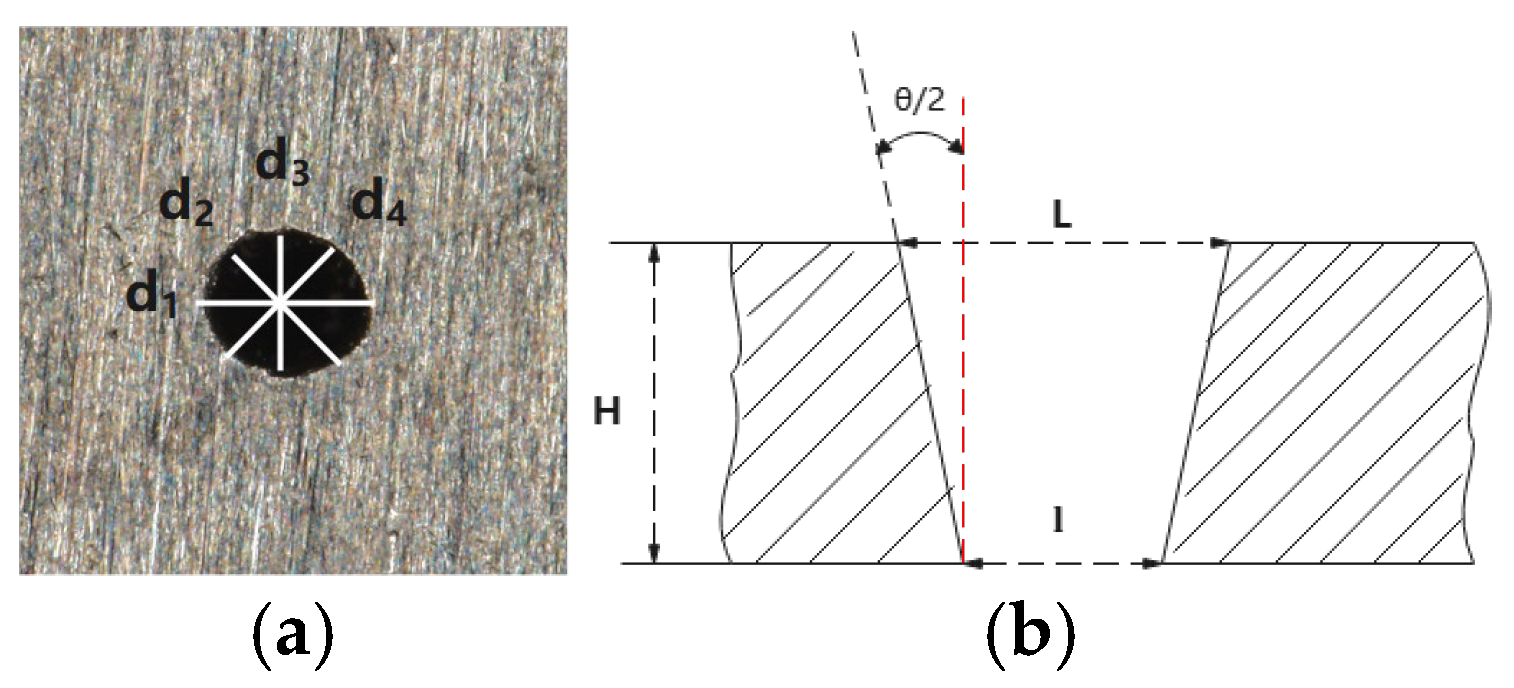
Figure 2 illustrates the measurement methods for hole quality indicators. Select the average value of four diameters with a 45° interval as the hole diameter value, with the following formula for calculating the hole diameter [19]:
d   =   d 1   +   d 2   +   d 3   +   d 4 4
In the formula, d1–d4 represent the lengths of the four diameters shown in the figure. Once the hole diameter is obtained, the roundness can be calculated using the following formula [20]:
C   = dmin   dmax
In the formula, dmin is the average of the two smaller diameters, and dmax is the average of the two larger diameters. The figure illustrates the taper measurement method, and the calculation formula is as follows [21]:
θ =   2 arctan L l 2 h × 180 ° π
In the formula, L is the entrance diameter, l is the exit diameter, and h is the workpiece thickness.

3. Results and Discussion

3.1. Comparison of Hole Quality Under Two Processing Paths

3.1.1. Effect of Pulse Energy on Drilling with Two Concentric Circle Processing Paths

The Figure 3 shows the micro-hole entrance and exit morphology for two concentric circle processing paths under different pulse energy levels (the experimental parameters are shown in Table 2 (No.1–No.4), with E1–E4 corresponding to micro-holes under the equidistant concentric circle path, and L1–L4 corresponding to micro-holes under the inner dense outer sparse concentric circle path; the upper part shows the entrance and the lower part shows the exit).
The results indicate that the equidistant concentric circle path overall provides a better hole quality. At different energy levels, the E group samples exhibit characteristics such as regular hole entrances, minimal spatter, and complete exit holes, especially under high-energy conditions, where the entrance is smooth and the morphology is stable. This is likely due to the path’s ability to achieve a more uniform energy distribution, allowing for the smooth removal of molten material and avoiding local over-melting and re-solidification. In contrast, the L group samples show issues such as irregular edges, spatter accumulation, and hole shape deviation, indicating that the inner-dense outer-sparse path suffers from insufficient melting at low energy and an excessive energy concentration at high energy, leading to uneven heat-affected zones and affecting the hole formation consistency. In conclusion, the equidistant concentric circle path demonstrates stronger energy control and processing stability, making it more suitable for high-quality micro-hole processing requirements.
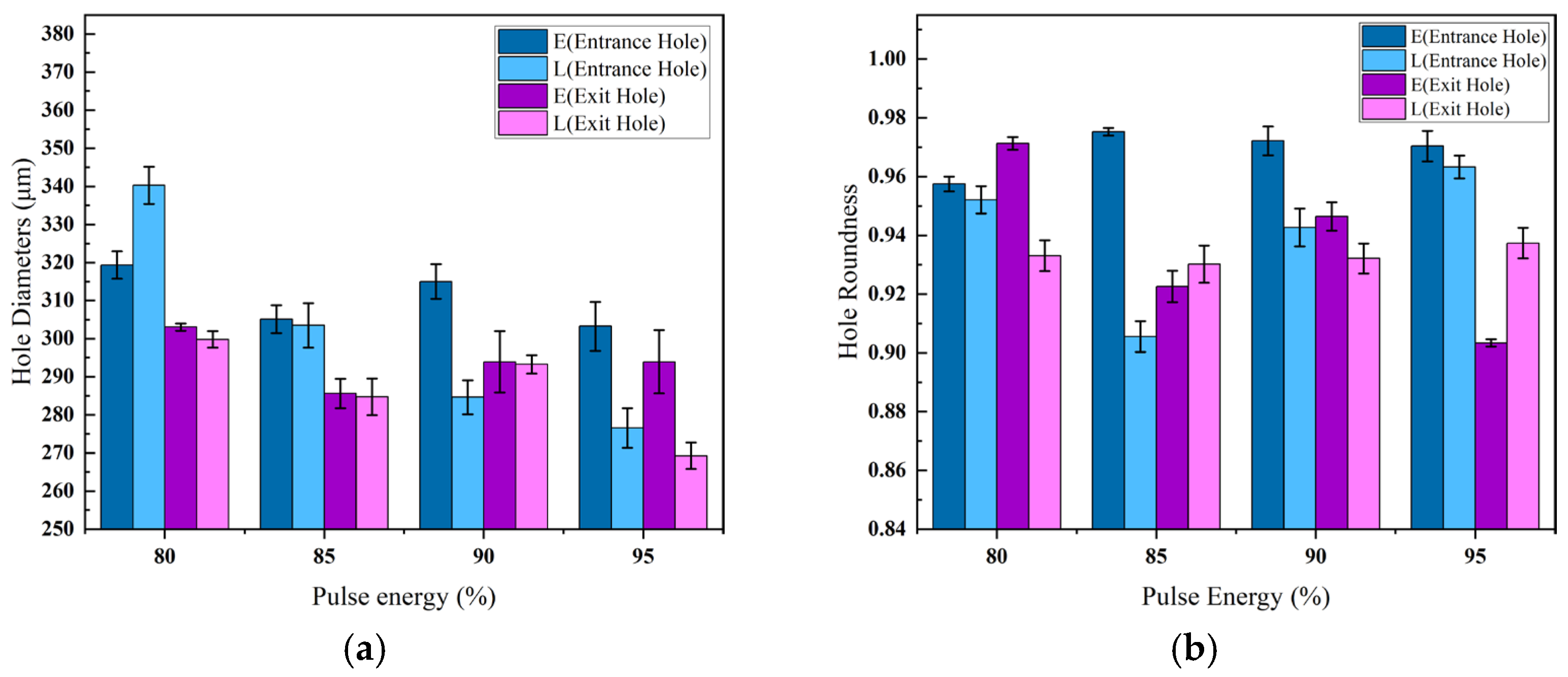
Figure 4a shows the effect of different pulse energies on the inlet and outlet apertures for two processing paths. In the equidistant concentric circle path, the aperture size remains stable with the pulse energy, indicating a good consistency and stability. In contrast, the inner-dense outer-sparse path exhibits significant aperture shrinkage as the pulse energy increases, reflecting the higher sensitivity to energy changes and greater fluctuation. As the pulse energy of the laser increases, the interaction between the laser and the material surface intensifies. The laser energy is absorbed by the material surface and converted into heat, causing the surface to rapidly heat up, leading to evaporation or vaporization. As the energy increases, the evaporated material undergoes further ionization, forming a denser plasma. High-density plasma has a significant impact on the laser beam, primarily through absorption and scattering effects. The free electrons and ions in the plasma absorb part of the laser energy, leading to energy attenuation, while the scattering of the laser beam further reduces the effective heating capability of the laser. This effect is particularly pronounced in the L processing path, where the laser energy is concentrated at the center of the hole, causing heat accumulation mainly in the central region, while the energy at the edges is lower, reducing the ablation effect. These two factors are the primary reasons for the reduction in hole diameter in the L path [22,23]. In contrast, the E path exhibits a more uniform distribution of laser energy across the entire processing area, leading to more evenly spread heat. This uniform heat distribution helps maintain a stable temperature, preventing significant thermal accumulation differences between the center and the edges of the hole, resulting in smaller variations in the hole diameter. Additionally, because the laser energy is evenly distributed, the plasma density is lower, leading to reduced scattering and absorption effects on the laser beam.
Figure 4b shows the effect of the pulse energy on the hole roundness under different processing paths. Overall, the concentric circle processing path produces better hole roundness at all energy levels compared to the inner-dense-and-outer-sparse path. Specifically, at an 85% pulse energy (total power of 30 W), the entry roundness reaches its optimal value, indicating that this path strategy is beneficial for achieving more regular hole shapes at moderate energy levels. In contrast, the inner-dense-and-outer-sparse path, due to an uneven energy distribution, is prone to excessive ablation and local collapse in the entry area, resulting in a greater fluctuation in roundness. Furthermore, as the pulse energy increases, the plasma shielding effect becomes more pronounced, potentially suppressing the effective action of the laser at the bottom of the hole, which further affects the symmetry of the exit hole.
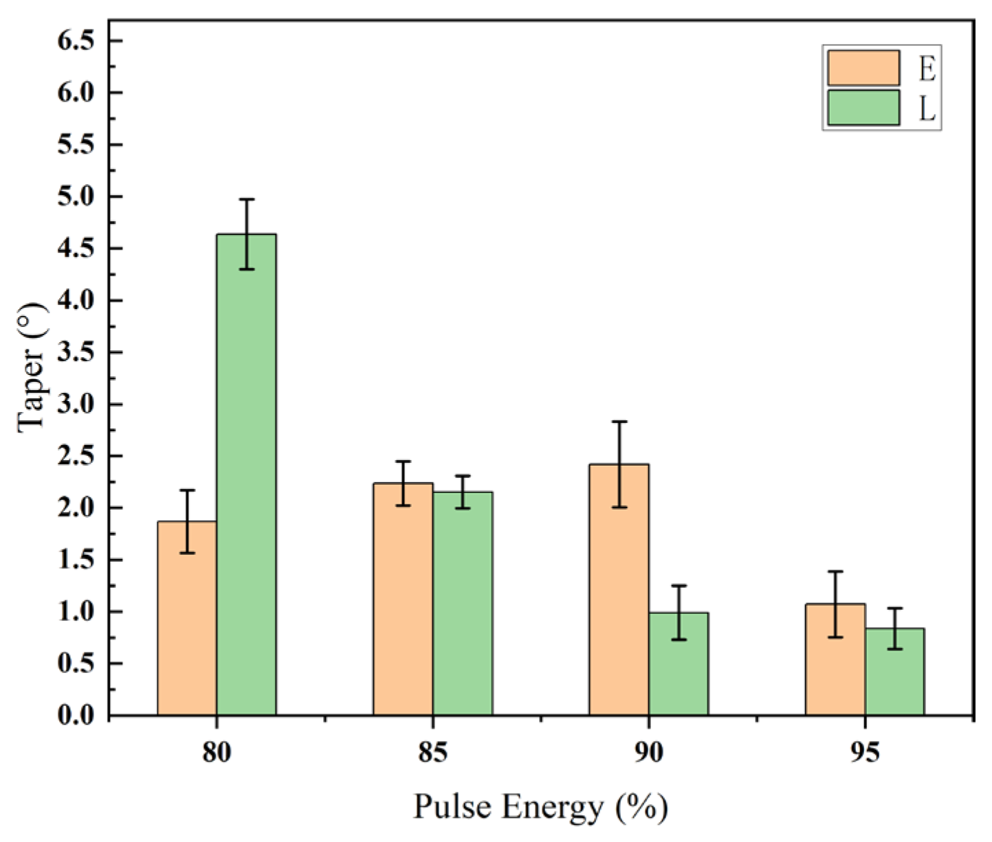
Figure 5 shows the effect of different pulse energies on the cone angle under two processing paths. The overall trend of the cone angle decreases as the pulse energy increases. In the inner-dense outer-sparse path, the cone angle of small holes decreases more significantly; however, at 90% energy, it exhibits a negative cone angle (with the hole outlet larger than the inlet). In contrast, the cone angle of small holes in the equidistant path changes less, with overall stable control, demonstrating a good processing consistency. It is noteworthy that, in the equidistant concentric circle path, when the pulse energy increases from 90% to 95%, the entrance diameter remains almost unchanged due to the constraint of the self-limiting effect [24]. Meanwhile, the net ablation capacity at the hole bottom exceeds the suppressive influence of plasma shielding, leading to enhanced keyhole stability and improved energy absorption at the bottom surface. This facilitates stronger downward ejection and material removal, while simultaneously reducing redeposition at the outlet, thereby enlarging the exit diameter and resulting in a pronounced reduction in taper.

3.1.2. Effect of Number of Scans on Hole Drilling for Two Concentric Circle Processing Paths

Figure 6 shows the entrance hole and exit hole morphology under two concentric circle processing paths at different scan numbers (the processing parameters are shown in Table 1 (No.5–No.8), with E5–E8 representing small holes under the concentric circle path and L5–L8 representing small holes under the inner-dense-and-outer-sparse concentric circle path; the entrance hole is shown at the top, and the exit hole at the bottom).
In the equidistant path (Group E), the edges of both the entrance hole and exit hole are generally smooth, with a uniform morphology. The hole diameter slightly increases with the number of scans, but the contour integrity remains good. Particularly in E6 and E7, the hole openings are nearly circular, with minimal slag attachment, demonstrating good stability. In contrast, for the inner-dense-and-outer-sparse path (Group L), as the number of scans increases, although there is a tendency for the hole diameter to expand, irregularities in the hole edge become more pronounced. Some exit holes show slag accumulation and contour damage, as seen in L7 and L8.
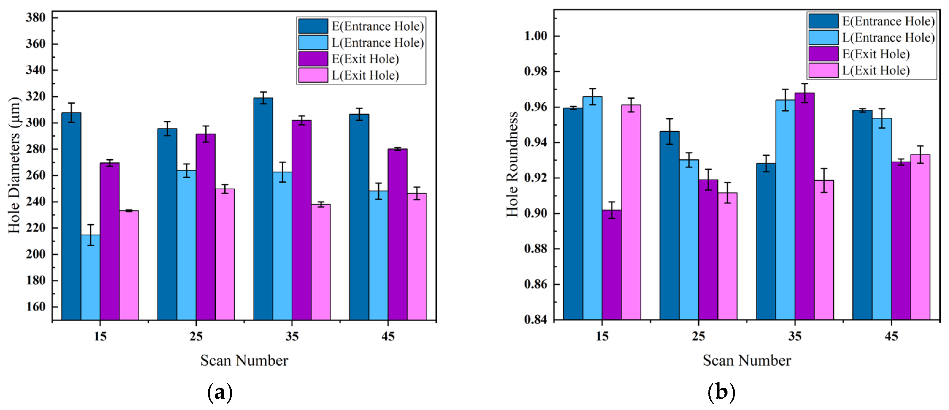
Figure 7a illustrates the effect of the scan number on the entrance and exit diameters of the micro-holes under the two different processing paths. In the equidistant concentric circle path (E), both the entrance and exit hole diameters exhibit a relatively stable increase with some fluctuation. After 25 to 35 scans, the hole diameter reaches its maximum size and then slightly decreases, showing an overall minimal variation and good process controllability. This is related to the uniform distribution of laser energy across the entire processing area, which ensures an even heat distribution, thus maintaining stable hole dimensions and a relatively consistent hole shape. In contrast, the inner-dense outer-sparse concentric circle path (L) shows more significant variations in hole diameter with larger fluctuations. Specifically, the entrance hole diameter rapidly increases from 15 scans to 25 scans and then gradually decreases. The exit hole diameter follows a similar trend but is consistently smaller than that of the equidistant path. In the L path, the laser energy is concentrated at the center of the hole, leading to a rapid initial ablation. However, as the scan number increases, the local heat accumulation effect becomes more pronounced, and plasma effects gradually emerge [25,26]. These factors combined reduce the subsequent effective ablation of the material, restricting further hole expansion and even leading to a reduction in hole diameter. Plasma effects cause the partial absorption and scattering of the laser energy, further reducing the effective energy transfer, which affects both the hole shape and diameter. These phenomena indicate that, with an increasing number of scans, the inner-dense outer-sparse path is more susceptible to heat accumulation and plasma shielding effects, ultimately impacting hole shape and quality. Overall, the equidistant concentric circle path demonstrates better hole diameter stability, while the inner-dense outer-sparse path exhibits more significant variations in hole diameter due to the increased sensitivity to the scan number and energy.
Figure 7b shows the effect of different scan numbers on the entrance hole and exit hole roundness under the two processing paths. Upon observation, it is evident that the equidistant concentric circle path exhibits minimal fluctuation in both the entrance hole and exit hole roundness, demonstrating better roundness stability. The exit hole roundness reaches its highest at 35 scans. In contrast, the inner-dense-and-outer-sparse path shows a more significant response to changes in the scan number, with greater fluctuations in roundness. However, a good hole shape can still be achieved at moderate scan numbers (such as 35 scans). Too few scans may result in insufficient ablation, while too many can lead to heat accumulation and edge collapse, both of which can affect the hole symmetry.
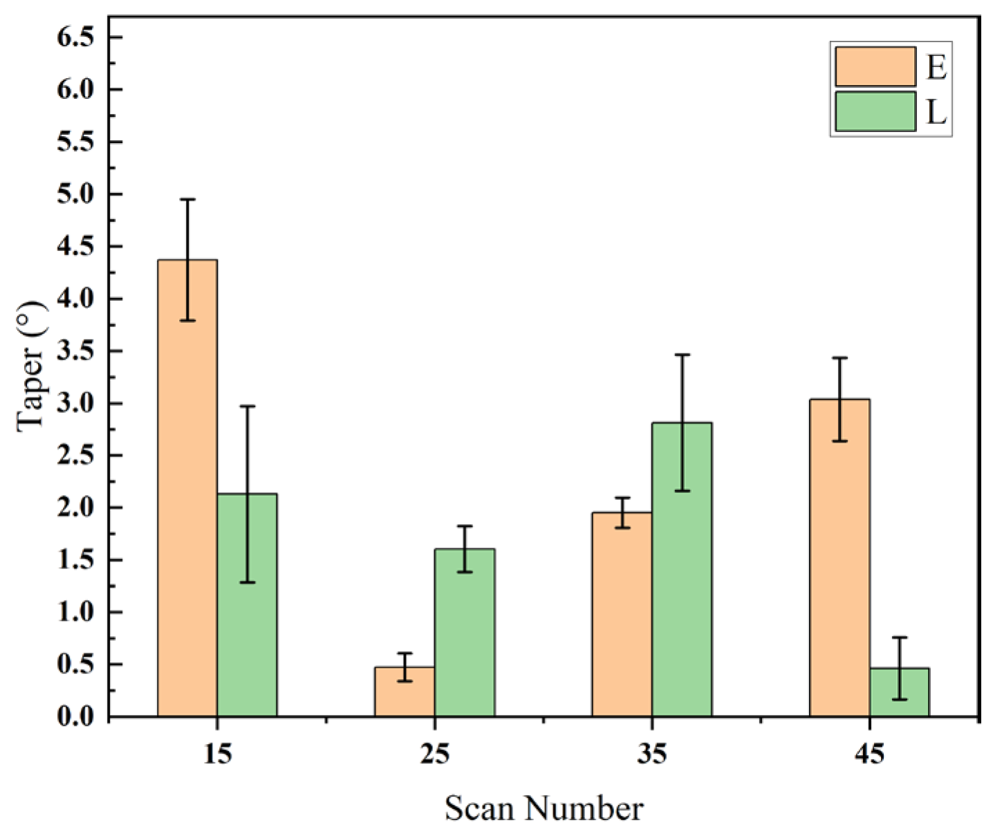
Figure 8 shows the effect of different scanning numbers on the cone angle under two processing paths. The overall fluctuation of both processing paths is relatively large, possibly due to the laser concentration at low scanning numbers, which is prone to forming larger cone angles. In the inner-dense outer-sparse path, a negative cone angle is observed at 15 scanning passes, which may be due to the heat accumulation effect at the hole outlet being greater than the ablation effect at the hole inlet when the scanning number is low.

3.1.3. Effect of Scan Speed on Hole Drilling for Two Concentric Circle Processing Paths

Figure 9 shows the entrance hole and exit hole morphology under two concentric circle processing paths at different scan speeds (the processing parameters are shown in Table 1 (No.9–No.12), with E9–E12 representing small holes under the equidistant concentric circle path and L9–L12 representing small holes under the inner-dense-and-outer-sparse concentric circle path; the entrance hole is shown at the top, and the exit hole at the bottom).
It can be observed that, under the equidistant concentric circle processing path, as the scan speed increases, the surface spatter of the entrance hole first increases and then decreases, while the surface spatter of the exit hole gradually increases. Under the inner-dense-and-outer-sparse concentric circle processing path, as the scan speed increases, the surface spatter of the entrance hole first increases and then decreases, but the entrance hole shape gradually becomes irregular. The surface spatter on the exit hole also gradually increases.
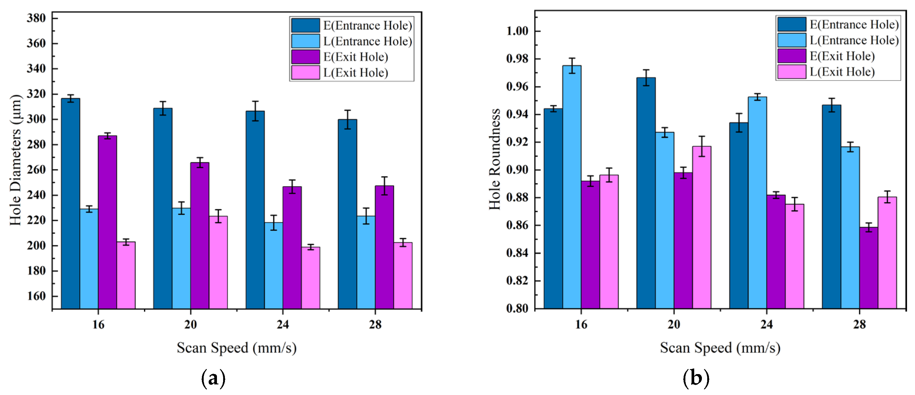
Figure 10a shows the effect of different scan speeds on the entrance and exit hole diameters under two processing paths. The equidistant concentric circle path maintains hole diameters close to the preset values, especially within the 20–24 mm/s range, with a small deviation and stable control. In contrast, the inner-dense-and-outer-sparse path results in smaller diameters with larger fluctuations, making it harder to consistently achieve the target size. This is likely because the equidistant path evenly distributes laser energy, maintaining a stable energy density, while the inner-dense-and-outer-sparse path concentrates energy in the hole center. As the scan speed increases, the laser exposure time shortens, leading to insufficient ablation at the exit hole edge, which is below the target size of 300 mm.
Figure 10b shows the effect of different scan speeds on the entrance hole and exit hole roundness under two processing paths. The equidistant concentric circle path exhibits minimal fluctuation in the entrance hole roundness, demonstrating stability, while the exit hole roundness decreases significantly as the scan speed increases. On the other hand, the inner-dense-and-outer-sparse path achieves the best roundness near 20 mm/s, with the roundness decreasing at both higher and lower speeds.
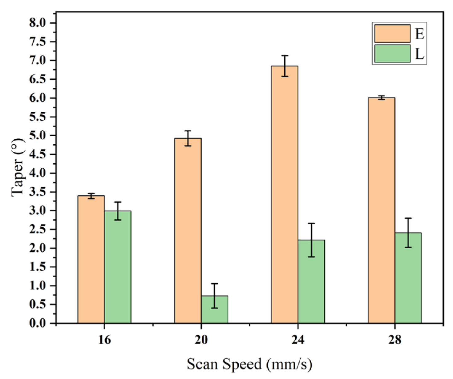
Figure 11 shows the variation in hole taper under two processing paths at different scan speeds. The results indicate that, for the equidistant concentric circle path, the taper generally increases with speed, with significant overall fluctuations. In contrast, the inner-dense-and-outer-sparse path achieves the lowest taper around 20 mm/s, with smaller overall changes, providing more stable control.

3.2. Selection of Processing Path

Through the above single-factor comparison experiments, the effects of pulse energy, scan number, and scan speed on hole quality under two concentric circle processing paths were explored in depth. From the results, the hole taper range for the equidistant concentric circle path is from 0.371° to 6.891°, with an average of 3.18° and a standard deviation of 1.89°. The hole taper for the inner-dense-and-outer-sparse path ranges from −2.075° to 4.880°, with an average of 1.46° and a standard deviation of 1.75° (Table 3). Although the latter path shows better overall taper control and even presents a negative taper (i.e., the hole bottom is slightly larger than the hole opening) in some cases, it exhibits morphological reverse shrinkage, which is unfavorable for the subsequent optimization of the processing parameters.
To clearly compare the differences between the two, SEM images of small holes from experiments with the two processing paths are shown. The figure displays SEM images of SUS304 stainless steel holes drilled using picosecond lasers with the two different scanning paths (the equidistant concentric circle and inner-dense-and-outer-sparse concentric circle). In each set of images, the top shows the entrance hole and the bottom shows the exit hole.
From Figure 12a, it can be seen that the hole edge processed with the equidistant concentric circle path is relatively neat, with clear contours and fewer splatters. The hole opening is nearly circular, indicating that this path helps maintain a uniform laser energy distribution. Although there is some burr and particle deposition at the exit hole, the overall morphology is symmetrical, with no obvious edge collapse. In contrast, after processing with the inner-dense-and-outer-sparse path (Figure 12b), the hole opening exhibits noticeable irregular molten edges and more splatter residue. In some areas, collapse and local ablation traces are even observed, indicating that an uneven energy distribution may lead to localized over-ablation. The morphology at the exit hole is relatively rough, with a wide distribution of splatter and poor taper consistency. Considering the controllability of the processing path, morphological consistency, and suitability for subsequent optimization experiments, the equidistant concentric circle path was ultimately selected for the orthogonal experiments in this study to obtain a more engineering-applicable set of processing parameters.

3.3. Parameter Optimization

This experiment investigates three processing parameters: pulse energy, scan number, and scan speed. Each factor is set at three levels. The experiment uses the L9 (33 standard orthogonal table, as shown in Table 4.

3.3.1. Hole Diameter

  • Entrance Hole Diameter
Table 5 presents the analysis of the entrance hole diameter results from the orthogonal experiment. The influence of the three factors on the entrance hole diameter, ranked from largest to smallest, is as follows: scan number, scan speed, and pulse energy. Since the preset hole diameter is 300 μm, the parameter combination with the inlet diameter closest to 300 μm should be selected from the table. The optimal laser-processing parameter combination is A3B1C3, i.e., pulse energy at 90% (total power 30 W), scan number 25, and scan speed 24 mm/s.
Figure 13 shows the effect of each factor on the entrance hole diameter. Based on the optimal laser parameter combination, it can be concluded that a pulse energy of 85–90%, a scan number of 25–35, and a scan speed of 20–24 mm/s are the most ideal processing parameters.
2.
Exit Hole Diameter
Table 6 presents the analysis of the exit hole diameter results from the orthogonal experiment. The influence of the three factors on the exit hole diameter, ranked from largest to smallest, is as follows: pulse energy, scan number, and scan speed. Since the preset hole diameter is 300 μm, the parameter combination with the largest exit hole diameter should be selected from the table. The optimal laser processing parameter combination is A3B3C1, i.e., pulse energy at 90% (total power 30 W), scan number 45, and scan speed 16 mm/s.
Figure 14 shows the effect of each factor on the exit hole diameter. Based on the optimal laser parameter combination, it can be concluded that a pulse energy of 85–90%, a scan number of 35–45, and a scan speed of 16–20 mm/s are the most ideal processing parameters.

3.3.2. Roundness

  • Entrance Hole Roundness
Table 7 presents the analysis of the entrance hole roundness results from the orthogonal experiment. The influence of the three factors on the entrance hole roundness, ranked from largest to smallest, is as follows: scan number, scan speed, and pulse energy. Since the preset hole diameter is 300 μm, the parameter combination with the entrance hole roundness closest to 1 should be selected from the table. The optimal laser processing parameter combination is A3B2C2, i.e., pulse energy at 90% (total power 30 W), scan number 35, and scan speed 20 mm/s.
Figure 15 shows the effect of each factor on the entrance hole roundness. Based on the optimal laser parameter combination, it can be concluded that a pulse energy of 85–90%, a scan number of 35–45, and a scan speed of 20–24 mm/s are the most ideal processing parameters.
2.
Exit Hole Roundness
Table 8 presents the analysis of the exit hole roundness results from the orthogonal experiment. The influence of the three factors on the outlet roundness, ranked from largest to smallest, is as follows: scan number, scan speed, and pulse energy. The parameter combination with exit hole roundness closest to 1 should be selected from the table. The optimal laser processing parameter combination is A3B3C1, i.e., pulse energy at 90% (total power 30 W), scan number 45, and scan speed 16 mm/s.
Figure 16 shows the effect of each factor on the exit hole roundness. Based on the optimal laser parameter combination, it can be concluded that a pulse energy of 85–90%, a scan number of 35–45, and a scan speed of 16–20 mm/s are the most ideal processing parameters.

3.3.3. Taper

Table 9 presents the analysis of the taper results from the orthogonal experiment. The influence of the three factors on taper, ranked from largest to smallest, is as follows: pulse energy, scan speed, and scan number. The parameter combination with the smallest taper should be selected from the table. The optimal laser processing parameter combination is A3B1C1, i.e., pulse energy at 90% (total power 30 W), scan number 25, and scan speed 20 mm/s.
Figure 17 shows the effect of each factor on the taper. Based on the optimal laser parameter combination, it can be concluded that a pulse energy of 85–90%, a scan number of 25–35, and a scan speed of 20–24 mm/s are the most ideal processing parameters.

3.4. Parameter Optimization Results

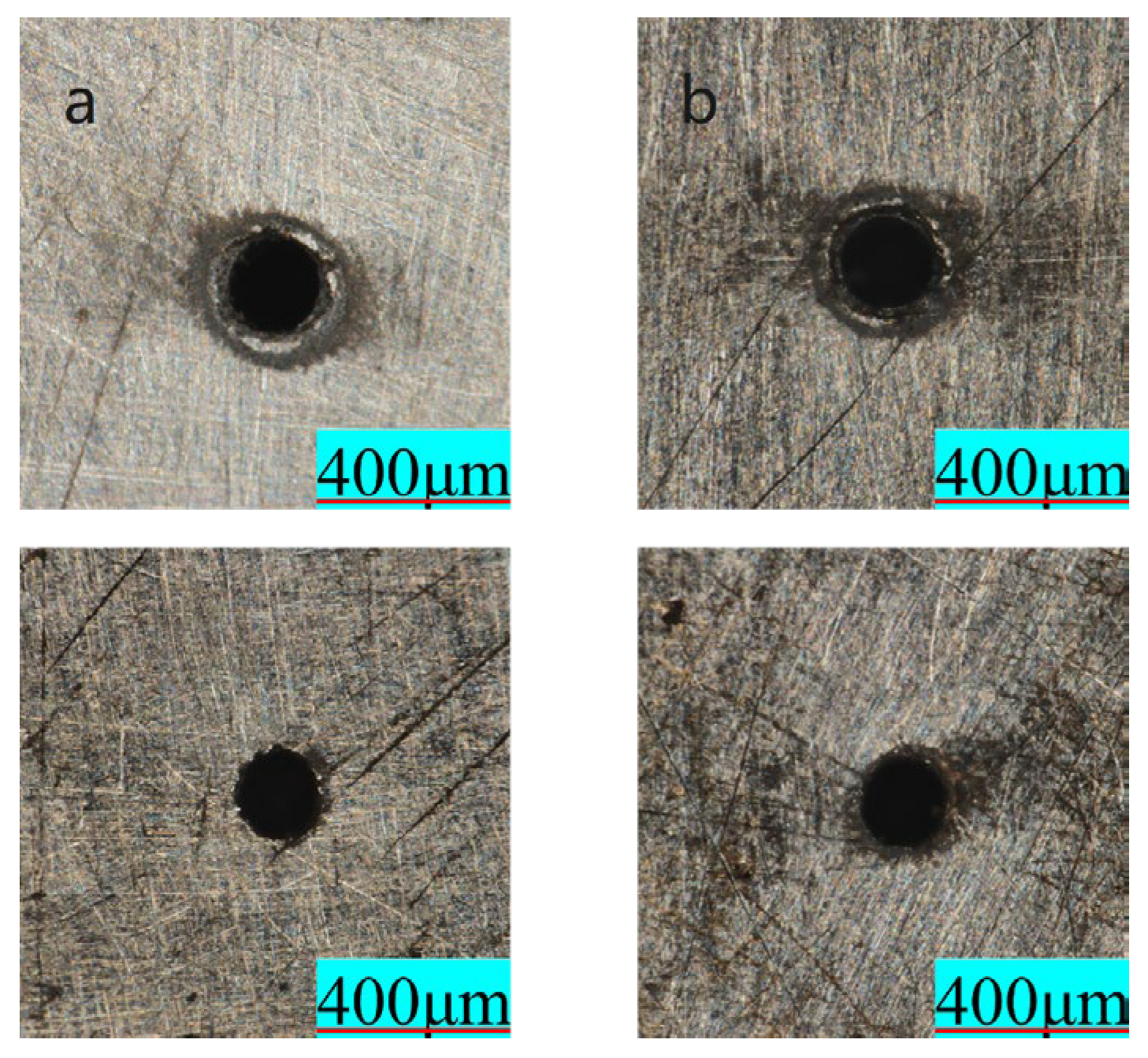
According to the comprehensive balance method, the optimal processing parameters are pulse energy at 90% (total power 30 W), scan number at 25, and scan speed at 16 mm/s, and pulse energy at 90% (total power 30 W), scan number at 45, and scan speed at 20 mm/s, corresponding to Figure 18a and b, respectively.
From the images, it can be seen that hole “a” has a smooth inlet with fewer burrs, a smaller heat-affected zone, a uniform outlet diameter, and no significant slag residue, demonstrating a higher overall hole quality. In contrast, hole “b,” while fully perforated, shows a noticeable heat-affected zone and edge ablation at the inlet, and the outlet exhibits some degree of blackening and contour blurring, which is suspected to be caused by multiple scans leading to heat accumulation and enhanced plasma shielding effects. Therefore, considering factors such as hole integrity, edge neatness, and slag control, hole “a” not only ensures hole connectivity but also demonstrates superior hole morphology, making it more suitable as the recommended parameter combination for the laser drilling of this material, i.e., pulse energy at 90%, scan number 25, and scan speed 16 mm/s—the highest-quality micro-hole obtained in this study had an entrance diameter of 301.125 μm, an exit diameter of 297.833 μm, a roundness of 0.995, and a taper angle of 0.377°.
To highlight the novelty of this study, the optimized results were benchmarked against the existing literature in the field of laser drilling (see Table 10). It should be noted that direct quantitative comparisons are challenging due to differences in the experimental conditions, such as the material thickness and the type of laser system used. Nevertheless, a comparison of the key quality metrics, including the hole diameter, roundness, and taper, clearly demonstrates the superiority of the optimization process developed in this work for micro-hole quality control.
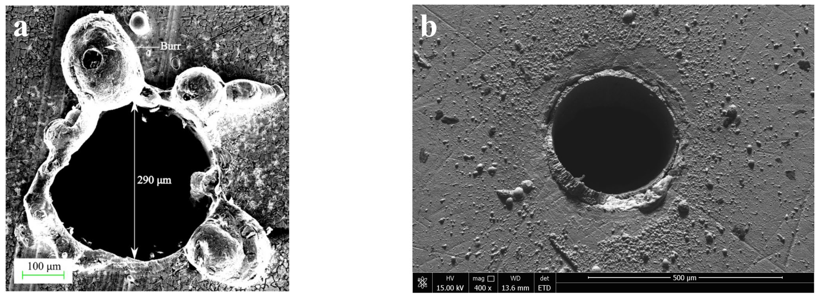
It is noteworthy that, in this laser machining process, the control of the spatter and the heat-affected zone is also superior to that of conventional long-pulse laser machining, as shown in Figure 19.
In conventional long-pulse or millisecond laser drilling, heat diffuses significantly into the surrounding material, resulting in a large heat-affected zone (HAZ) and pronounced thermal damage. In contrast, picosecond lasers, owing to their ultrashort pulse duration, achieve a highly localized energy deposition, which effectively suppresses the thermal conduction and, thereby, minimizes the HAZ. This characteristic explains the greater stability in the entrance morphology and hole diameter observed under the equidistant concentric circle path in Figure 19a,b. On the other hand, during long-pulse laser drilling, the stronger recoil pressure drives large amounts of molten material to eject from the hole entrance, leading to a pronounced spatter formation, as shown in Figure 19b.
Compared with previous studies, the present work demonstrates several notable advantages. For instance, a prior study developed a two-step processing strategy based on sequential penetration and modification for fabricating micro-holes in 304 stainless steel, achieving excellent results in reducing taper and minimizing the heat-affected zone (HAZ). While their approach performed well in these aspects, the equidistant concentric circle scanning path proposed in this work also exhibits outstanding performance in taper control, with the additional benefit of single-step processing, which offers significant time efficiency. Furthermore, although millisecond laser processing has also shown good taper control, the present study clearly outperforms in terms of spatter suppression.

4. Conclusions

This study systematically investigates the effects of the processing path and laser parameters on the hole morphology quality during picosecond laser drilling of stainless steel using a combination of numerical simulation and experimental methods. The numerical simulation primarily simulates the drilling process, providing the initial reference data for the experiments. The experimental results show that the equidistant concentric circle path outperforms the inner-dense-and-outer-sparse concentric circle paths in terms of the hole diameter consistency, roundness stability, and taper control. This path exhibits a more uniform energy distribution and better process controllability, making it more suitable for high-quality micro-hole processing. Regarding laser parameters, increasing the pulse energy enhances the bottom ablation capacity and reduces the taper, but excessive pulse energy may exacerbate the plasma shielding effects. Increasing the scan number helps with energy accumulation and hole contour symmetry, but excessive scanning can lead to thermal expansion at the hole inlet. Increasing the scan speed reduces spattering and excessive ablation within certain limits, but excessive speed may result in an insufficient energy density, causing a reduction in the hole diameter. Two optimal processing parameter sets were identified through orthogonal experiments: pulse energy at 90%, scan number 25, and scan speed 16 mm/s; and pulse energy at 90%, scan number 45, and scan speed 20 mm/s. Among these, the first set demonstrated better performance in terms of edge neatness and thermal impact control.
It should be noted that this study was conducted within a limited range of parameters, with all experiments performed on stainless steel specimens of 0.5 mm thickness. While the findings provide valuable insights, the generalizability of the results may be constrained. Therefore, future research should verify whether these conclusions are applicable to other materials and account for the influence of different laser systems and processing environments. Such efforts will help enhance the broader applicability of the conclusions and provide stronger theoretical support for the use of laser-processing technology in other high-temperature materials.

Author Contributions

Methodology, and writing—original draft, C.W.; funding acquisition, project administration, and supervision, L.W.; validation, L.X.; software, and validation, Y.R.; funding acquisition, K.X. All authors have read and agreed to the published version of the manuscript.

Funding

This research was supported by the National Natural Science Foundation of China (grant numbers 52375434 and 52205469), Major Research Projects of the Natural Science Research Foundation of Jiangsu Higher Education Institutions (grant number 23KJA460003) and the Postgraduate Research & Practice Innovation Program of Huaiyin Institute of Technology (No. HGYK202508).

Data Availability Statement

The original contributions presented in the study are included in this article. Further inquiries can be directed to the corresponding author.

Conflicts of Interest

The authors declare no conflicts of interest.

References

  1. Balakrishnan, T.S.; Sultan, M.T.H.; Shahar, F.S.; Saravanakumar, Y.N.; Chandran, N.K. Aerospace steel: Properties, processing, and applications. In Aerospace Materials; Elsevier: Amsterdam, The Netherlands, 2025; pp. 275–290. [Google Scholar]
  2. Gao, J.; Cao, Y.; Ma, Y.; Zheng, K.; Zhang, M.; Hei, H.; Gong, H.; Yu, S.; Kuai, P.; Liu, K. Wear, corrosion, and biocompatibility of 316L stainless steel modified by well-adhered Ta coatings. J. Mater. Eng. Perform. 2022, 31, 8784–8798. [Google Scholar] [CrossRef]
  3. Sharma, R.; Pradhan, S.; Bathe, R.N. A review of machinability aspects of difficult-to-cut materials using microtexture patterns. In Advanced Manufacturing and Processing Technology; CRC Press: Boca Raton, FL, USA, 2020; pp. 45–65. [Google Scholar]
  4. Lin, G.; Shi, H.; Liu, X.; Wang, Z.; Zhang, H.; Zhang, J. Tool wear on machining of difficult-to-machine materials: A review. Int. J. Adv. Manuf. Technol. 2024, 134, 989–1014. [Google Scholar] [CrossRef]
  5. Wang, C.; Wang, Q.; Qian, Q.; Di, B. The development of laser drilling: A review. IOP Conf. Ser. Mater. Sci. Eng. 2020, 782, 022067. [Google Scholar] [CrossRef]
  6. Szwajka, K.; Zielińska-Szwajka, J.; Żaba, K.; Trzepieciński, T. An Investigation of the Sequential Micro-Laser Drilling and Conventional Re-Drilling of Angled Holes in an Inconel 625 Ni-Based Alloy. Lubricants 2023, 11, 384. [Google Scholar] [CrossRef]
  7. Winter, J.; Spellauge, M.; Hermann, J.; Eulenkamp, C.; Huber, H.P.; Schmidt, M. Ultrashort single-pulse laser ablation of stainless steel, aluminium, copper and its dependence on the pulse duration. Opt. Express 2021, 29, 14561–14581. [Google Scholar] [CrossRef]
  8. Gu, Z.; He, Y.; Ji, J.; Wei, Y.; Fu, Y. Reducing the taper and heat-affected zone in nanosecond laser drilling of CFRP plate using backside sacrificial layer. Opt. Lasers Eng. 2025, 185, 108735. [Google Scholar] [CrossRef]
  9. Zhang, R.; Zhang, H.; Ke, R.; Wang, X. Fabrication of high aspect ratio and low taper angle micro-holes utilizing complex water-assisted femtosecond laser drilling. Opt. Laser Technol. 2025, 185, 112608. [Google Scholar] [CrossRef]
  10. Gu, Z.; He, Y.; Ji, J.; Fu, Y. Numerical simulation and experimental study of the shape variation influence on stainless steel drilling with picosecond laser. Opt. Laser Technol. 2025, 181, 112021. [Google Scholar] [CrossRef]
  11. Bara, A.; Sahoo, S.K.; Naik, S.S.; Sahu, A.K.; Mahapatra, S.S. Multi response optimization of Nd: YAG laser micro drilling characteristics of 304 stainless steel using desirability function approach. Mater. Today Proc. 2018, 5, 18975–18982. [Google Scholar] [CrossRef]
  12. Schneller, L.; Henn, M.; Spurk, C.; Olowinsky, A.; Beckmann, F.; Moosmann, J.; Holder, D.; Hagenlocher, C.; Graf, T. High-speed X-ray imaging of bulge formation during laser percussion drilling with various polarizations in stainless steel. Procedia CIRP 2024, 124, 644–648. [Google Scholar] [CrossRef]
  13. Zhang, H.; Mao, Y.; Kang, M.; Ma, C.; Li, H.; Zhang, Y.; Wang, X. Fabrication of High Aspect Ratio Micro-Holes on 304 Stainless Steel Via Backside-Water-assisted Laser Drilling. Opt. Lasers Eng. 2023, 162, 107426. [Google Scholar] [CrossRef]
  14. Gu, Z.; He, Y.; Yang, J.; Fu, Y.; Ji, J.; Zhang, Y.; Li, J.; Liu, G. Dual-path Micro-Holes Process for 0cr17ni7al Stainless Steel Thin Plate with Picosecond Laser. J. Manuf. Process. 2023, 101, 1224–1233. [Google Scholar] [CrossRef]
  15. Zhang, Y.; He, X.; Yu, G.; Li, S.; Tian, C.; Ning, W.; Zhang, Y. Dynamic Evolution of Keyhole During Multi-Pulse Drilling with a Millisecond Laser on 304 Stainless Steel. Opt. Laser Technol. 2022, 152, 108151. [Google Scholar] [CrossRef]
  16. Brinkmeier, D.; Holder, D.; Loescher, A.; Röcker, C.; Förster, D.J.; Onuseit, V.; Weber, R.; Abdou, A.M.; Graf, T. Process Limits for Percussion Drilling of Stainless Steel with Ultrashort Laser Pulses at High Average Powers. Appl. Phys. 2021, 128, 35. [Google Scholar] [CrossRef]
  17. Wang, L.; Rong, Y.; Xu, L.; Wu, C.; Xia, K. Process Optimization on Trepanning Drilling in Titanium Alloy Using a Picosecond Laser via an Orthogonal Experiment. Micromachines 2025, 16, 846. [Google Scholar] [CrossRef]
  18. Wang, L.; Wu, C.; Rong, Y.; Xu, L.; Xia, K. Experimental Study on Millisecond Laser Percussion Drilling of Heat-Resistant Steel. Materials 2025, 18, 3699. [Google Scholar] [CrossRef]
  19. Namdev, S.; Pandey, A.; Pandey, A.K.; Kumar, R. Modeling of hole geometrical features in laser drilling of AISI316L sheet. J. Eng. Res. 2022, 10, 194–204. [Google Scholar] [CrossRef]
  20. Li, Z.; Allegre, O.; Guo, W.; Gao, W.-Y.; Li, B.-H.; Feng, Q.-L.; Wu, X.-P.; Li, L. Ultrafast Laser Drilling of Crack-free, Debris-free and Heat Affected Zone (HAZ)-free Blind Holes in Al2O3 with Flat Bottom and Reduced Taper Angles. Lasers Eng. 2020, 46, 367–381. [Google Scholar]
  21. Liu, X.; Chen, L.; Wang, X.; Zhengjun, X. Micromilling blind holes in Al2O3 ceramics using UV laser. Laser Optoelectron. Prog. 2021, 58, 0514005. [Google Scholar] [CrossRef]
  22. Li, J.; Zhang, W.; Zheng, H.; Gao, J.; Jiang, C. Reducing plasma shielding effect for improved nanosecond laser drilling of copper with applied direct current. Opt. Laser Technol. 2023, 163, 109372. [Google Scholar] [CrossRef]
  23. Chen, L.; Deng, H.; Xiong, Z.; Guo, J.; Liu, Q.; Li, G.; Shang, L. Investigation of shielding effects on picosecond laser-induced copper plasma characteristics under different focusing distances. Photonics 2021, 8, 536. [Google Scholar] [CrossRef]
  24. Salama, A.; Yan, Y.; Li, L.; Mativenga, P.; Whitehead, D.; Sabli, A. Understanding the self-limiting effect in picosecond laser single and multiple parallel pass drilling/machining of CFRP composite and mild steel. Mater. Des. 2016, 107, 461–469. [Google Scholar] [CrossRef]
  25. Zhou, T.; Hong, Y.; Fang, Z.; Perrie, W.; Fei, Y.; Hu, Y.; Edwardson, S.; Dearden, G. Experimental and numerical study of multi-pulse picosecond laser ablation on 316 L stainless steel. Opt. Express 2023, 31, 38715–38727. [Google Scholar] [CrossRef] [PubMed]
  26. Chang, Y.J.; Wang, C.S.; Manikanta, G.; Hsiao, Y.H. Laser-induced Plasma Detection for Laser Percussion Drilling of Stainless Steel and CoCrMo Alloy. Sens. Mater. 2025, 37, 93–104. [Google Scholar] [CrossRef]
  27. Gupta, A.K.; Singh, R.; Marla, D. Millisecond Pulsed Laser Micro-drilling of Stainless Steel—Optimizing Hole Quality Using Response Surface Methodology. J. Laser Micro Nanoeng. 2023, 18, 187–195. [Google Scholar]
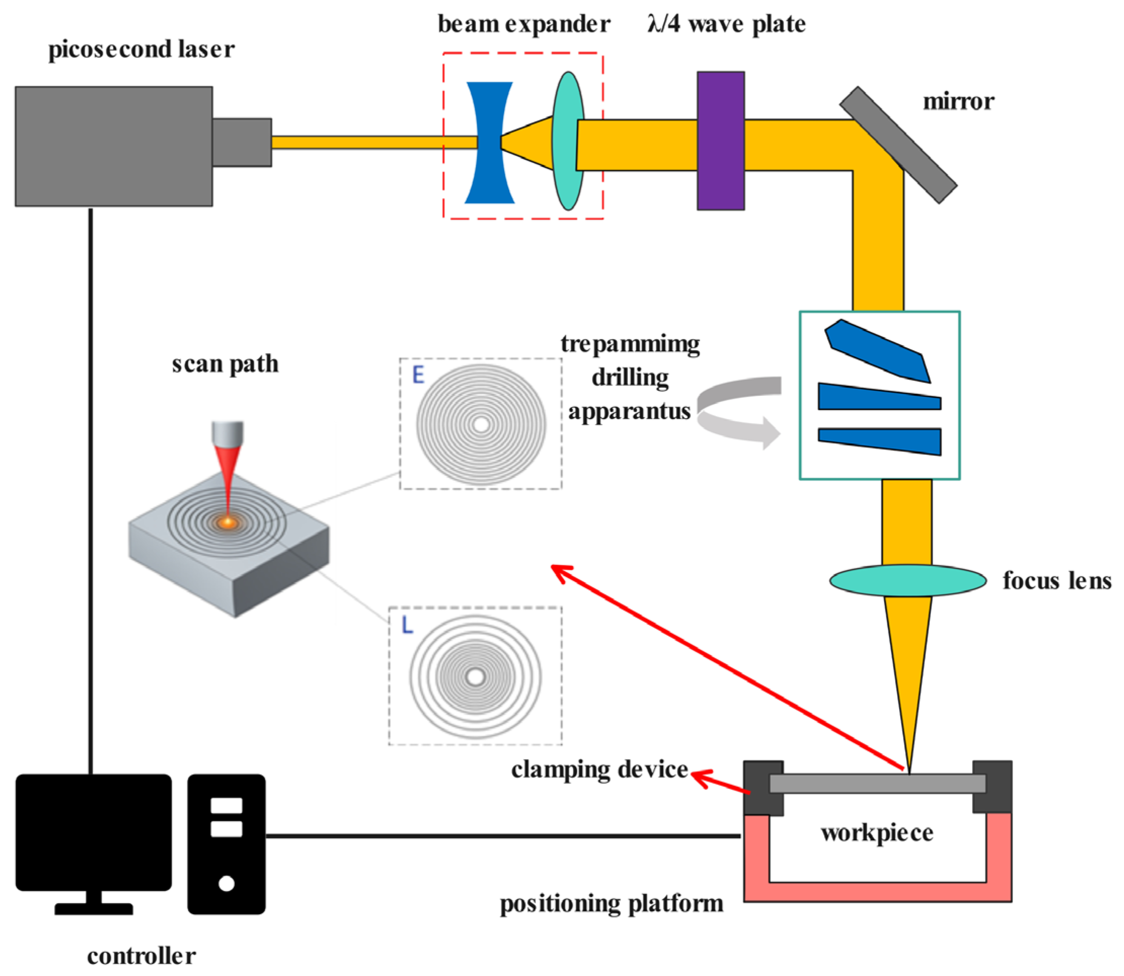
Figure 1. Schematic diagram of micro-hole laser processing with two scan paths (E represents equidistant concentric circles, and L represents inner-dense outer-sparse concentric circles).
Metals 15 01024 g001
Figure 2. Measurement methods for micro-hole quality indicators (a) hole diameter measurement method, and (b) taper measurement method), reprinted from Ref. [18].
Metals 15 01024 g002
Figure 3. Entrance and exit morphology for two concentric circle processing paths with varying pulse energy: (a) E1–E4 are microporous structures formed under isocentric circular paths at different energy levels (80%, 85%, 90%, and 95%); and (b) L1–L4 are microporous structures formed under isocentric circular paths with dense inner and sparse outer regions at different energy levels (80%, 85%, 90%, and 95%).
Metals 15 01024 g003
Figure 4. Effect of pulse energy on hole diameters and hole roundness: (a) the effect of pulse energy on hole diameters; and (b) the effect of pulse energy on hole roundness.
Metals 15 01024 g004
Figure 5. Effect of pulse energy on taper.
Metals 15 01024 g005
Figure 6. Entrance and exit morphology under two concentric circle processing paths with varying scan numbers: (a) E5–E8 are micro-holes under isometric concentric circular paths with different scanning number (15, 25, 35, and 45); and (b) L5–L8 are micro-holes under concentric circular paths with dense inner and sparse outer layers with different scanning number (15, 25, 35, and 45).
Metals 15 01024 g006
Figure 7. Effect of scan number on hole diameters and hole roundness: (a) the effect of scan number on hole diameters; and (b) the effect of scan number on hole roundness.
Metals 15 01024 g007
Figure 8. Effect of scan number on taper.
Metals 15 01024 g008
Figure 9. Entrance and exit morphology under two concentric circle processing paths with varying scan speeds: (a) E9–E12 represent micro-holes under isometric concentric circular paths at different scanning speeds (16 mm/s, 20 mm/s, 24 mm/s, and 28 mm/s); and (b) L9–L12 represent micro-holes under inner-dense-and-outer-sparse concentric circular paths at different scanning speeds (16 mm/s, 20 mm/s, 24 mm/s, and 28 mm/s).
Metals 15 01024 g009
Figure 10. Effect of scan speed on hole diameters and hole roundness: (a) the effect of scan speed on hole diameters; and (b) the effect of scan speed on hole roundness.
Metals 15 01024 g010
Figure 11. Effect of scan speed on taper.
Metals 15 01024 g011
Figure 12. SEM images of holes drilled using two processing paths (the top and bottom of the images represent the entrance hole and exit hole, respectively): (a) E processing path, and (b) L processing path.
Metals 15 01024 g012
Figure 13. Effect of each factor on entrance hole diameter.
Metals 15 01024 g013
Figure 14. Effect of each factor on exit hole diameter.
Metals 15 01024 g014
Figure 15. Effect of each factor on entrance hole roundness.
Metals 15 01024 g015
Figure 16. Effect of each factor on exit hole roundness.
Metals 15 01024 g016
Figure 17. Effect of each factor on taper.
Metals 15 01024 g017
Figure 18. Orthogonal optimal parameters for two small holes: (a) energy at 90% (total power 30 W), scan number at 25, and scan speed at 16 mm/s; (b) pulse energy at 90% (total power 30 W), scan number at 45, and scan speed at 20 mm/s (The entrance is shown in the first row, and the exit is shown in the second row).
Metals 15 01024 g018
Figure 19. Comparison of spatter in laser-fabricated micro-holes: (a) morphology of micro-holes processed by millisecond laser, Reprinted with permission from Ref. [27], Copyright 2023 The Japan Laser Processing Society; (b) morphology of micro-holes processed by picosecond laser in this study.
Metals 15 01024 g019
Table 1. Chemical composition and content of SUS304 stainless steel.
Material GradeChemical Composition and Content (%)
SUS304C ≤ 0.08Mn ≤ 2.00Si ≤ 1.00P ≤ 0.045
S ≤ 0.03Ni 8.00–10.50Cr 18.00–20.00Fe Balance
Table 2. Experimental parameters for concentric circle path drilling.
Experiment No.Repetition Frequency (Hz)Pulse Energy (30 W) ProportionScanning NumberScanning Speed (mm/s)
1100080%2516
2100085%2516
3100090%2516
4100095%2516
5100080%1516
6100080%2516
7100080%3516
8100080%4516
9100080%2516
10100080%2520
11100080%2524
12100080%2528
Table 3. Hole taper for the two processing paths.
Experiment NumberTaper (E)/°Taper (L)/°
11.7814.880
21.9922.062
32.295−0.950
41.3260.854
54.250−2.075
60.3711.561
71.8292.727
83.2390.796
93.4262.714
104.7330.354
116.8912.254
126.0522.298
Table 4. Orthogonal experimental parameter combinations.
Experiment NumberA
Pulse Energy (30 W) Ratio
B
Scan Number
C
Scan Speed
180%2516 mm/s
280%3520 mm/s
380%4524 mm/s
485%2520 mm/s
585%3524 mm/s
685%4516 mm/s
790%2524 mm/s
890%3516 mm/s
990%4520 mm/s
Table 5. Entrance hole diameter range analysis.
LevelEntrance Hole Diameter (μm)
Pulse Energy (A)Scan Number (B)Scan Speed (C)
1 313.631 309.280 319.234
2 315.619 311.950 314.849
3 313.481 321.501 308.649
Range Analysis2.138 12.221 10.585
Table 6. Exit hole diameter range analysis table.
LevelExit Hole Diameter (μm)
Pulse Energy (A)Scan Number (B)Scan Speed (C)
1275.669281.228288.758
2289.278283.419287.200
3291.377291.666280.355
Range Analysis15.71810.4388.404
Table 7. Entrance hole roundness range analysis.
LevelEntrance Hole Roundness
Pulse Energy (A)Scan Number (B)Scan Speed (C)
10.9560.9440.953
20.9570.9760.968
30.9670.9610.960
Range Analysis0.0110.0320.015
Table 8. Exit hole roundness range analysis.
LevelExit Hole Roundness
Pulse Energy (A)Scan Number (B)Scan Speed (C)
10.9260.9390.950
20.9300.9260.925
30.9550.9460.935
Range Analysis0.0300.0200.026
Table 9. Taper range analysis.
LevelTaper/°
Pulse Energy (A)Scan Number (B)Scan Speed (C)
14.3493.2143.491
23.0183.2683.167
32.5333.4183.241
Range Analysis1.8170.2040.324
Table 10. Comparison of micro-hole quality in laser machining.
ResearchLaser TypeMaterial and ThicknessTaper (°)
Hailong Zhang [13]Picosecond laser304 stainless, 1 mm0.38
Vrvind Kumar Gupta [27]Millisecond Laser304 stainless, 3 mm0.38
This studyPicosecond laser304 stainless, 0.5 mm0.377
Disclaimer/Publisher’s Note: The statements, opinions and data contained in all publications are solely those of the individual author(s) and contributor(s) and not of MDPI and/or the editor(s). MDPI and/or the editor(s) disclaim responsibility for any injury to people or property resulting from any ideas, methods, instructions or products referred to in the content.