Article

The Effect of Mo on the Microstructure and Mechanical Properties of High-Manganese Railway Frog Steel Produced with the Thermal Mechanical Control Process

1
School of Civil Engineering, Southwest Jiaotong University, Chengdu 610031, China
2
China Railway Engineering Equipment Group Co., Ltd., Zhengzhou 450016, China
3
School of Materials Science and Engineering, Henan Polytechnic University, Jiaozuo 454003, China
4
State Key Laboratory of Metastable Materials Science and Technology, Yanshan University, Qinhuangdao 066004, China
5
China Railway Shanhaiguan Bridge Group Co., Ltd., Qinhuangdao 066004, China
*
Author to whom correspondence should be addressed.
Metals 2025, 15(9), 1025; https://doi.org/10.3390/met15091025
Submission received: 9 August 2025 / Revised: 4 September 2025 / Accepted: 8 September 2025 / Published: 16 September 2025

Abstract

The aim of this study is to investigate the influence of Mo on the microstructure and mechanical properties of railway frog steel. To address the challenges of a coarse microstructure and alloy element segregation caused by the current casting method of railway frog steel, the application of thermal mechanical control process (TMCP) technology can achieve a uniform and refined microstructure and stable mechanical properties, which is progress for the development of high-manganese railway frog steel. The TMCP of four experimental steels with varying Mo contents of 0.02~1.01 wt.% was simulated using a Gleeble 3500. The mechanical properties were tested, and the microstructure of each sample was characterized. A single austenite formed in each Mo-containing steel. With the increased Mo content, the grain boundary carbides decreased due to the formation of carbides within the grains, and the austenite and twin sizes were refined. Moreover, grain boundary strengthening and dislocation strengthening increased, while solid solution strengthening and precipitation strengthening had little effect, leading to an increase in the final yield strength. The contribution of dislocation strengthening to the yield strength was 51~56%, indicating that dislocation strengthening was the most significant strengthening method in the high-manganese railway frog steel produced using the TMCP. The impact energy showed a trend of first increasing and then decreasing, and the impact energy reached the highest point when the Mo content was 0.30 wt.%. In addition, the mechanisms governing the effect of increased Si in controlling the final microstructure and mechanical properties are discussed.

1. Introduction

High-manganese steel used in railway frogs is mainly produced with a casting process [1,2,3,4,5]. The microstructure is coarse austenite grains and continuous network carbides at the grain boundaries [6], resulting in deteriorated toughness, high crack sensitivity [7], and early failure under heavy load or high-frequency impact conditions [8]. The high-manganese railway frog steel produced via the thermo-mechanical control process (TMCP), through the synergistic effect of deformation strengthening and microalloying, refines the grains and optimizes the carbide distribution, thereby achieving performance improvement [9,10,11]. This casting and rolling process is also used in non-sparking metallic material [12]. In addition, cold spray thermal deposition technology is also often used to improve the performance of materials [13]. For high-manganese railway frog steel, the most effective production method for improving the mechanical properties of materials is the TMCP.
Molybdenum (Mo), as a strong carbide-forming element, has a complex influence on the microstructure and mechanical properties of high-manganese steel [14,15]. The addition of Mo can significantly refine austenite grains and promote the effect of twinning-induced plasticity by lowering the stacking fault energy (SFE) [16], thereby enhancing the work hardening capacity and wear resistance [17] while also improving the strength and toughness [18]. Moreover, Mo can effectively inhibit the formation of grain boundary network carbides, thereby enhancing the overall performance of the steel [19]. Mo can enhance the strength of high-manganese austenitic steel through solid solution- and precipitation-strengthening mechanisms [18]. The solid solution-strengthening effect of Mo is due to its high solubility in the austenite matrix [20,21], which can effectively impede dislocation movement and thereby enhance the yield strength and tensile strength of the steel [22,23]. In addition, Mo can form stable carbides with other elements such as titanium and vanadium, and these carbides can significantly enhance the hardness and wear resistance [24,25]. However, excessive Mo may lead to the segregation of carbides at the grain boundaries, resulting in a decrease in elongation and impact toughness [26].
Moon et al. [27] provided insights into the effect of Mo and Cr additions on the microstructure and mechanical properties of austenitic Fe-Mn-Al-C lightweight steels, highlighting the yield strength’s decrease with the addition of 3 wt.% Mo or 3 wt.% Cr due to the suppression of carbide precipitation. However, the yield strength dramatically increased when the Mo content exceeded 4 wt.% due to grain refinement and precipitation strengthening [26]. The studies by Sairam et al. [28] reported the effect of Mo on the recrystallization behavior of austenitic steels. When the Mo content is at a low level, solute dragging is the main cause of delayed recrystallization. When the Mo content increases to 2~3 wt.%, the grain boundary precipitates and solute dragging jointly lead to a delay in recrystallization. A recent study by Shi et al. [29] reported that the co-microalloying of elevated additions of Nb and Mo promotes the precipitation of Mo2C and nano-scale (Nb,Mo)C carbides and reduces the proportion of Σ3 boundaries in cast steel. Therefore, the optimization of Mo needs to take into account the synergistic effects of the grain size, carbides, and twins on mechanical properties.
Although there have been many studies on the application of Mo microalloying in high-manganese steel, most focus on the casting or solid solution state [1,2,3,4,5], and the mechanism of Mo action in the hot rolling process still lacks systematic analysis. Moreover, the above-mentioned studies usually focus on a high content level (1.0~5.0 wt.%) of Mo, while there are relatively few studies on low content levels (≤1.0 wt.%). In order to maximize the role of alloying elements in steel and reduce the cost of expensive alloying elements, the content of Mo in high-manganese railway frog steels produced via the TMCP needs to be optimized. Furthermore, the evolution of microstructures and the associated influence on the mechanical properties of high-manganese railway frog steels produced via the TMCP need to be clarified when the Mo content changes.
The effect of the Mo content on the microstructures and mechanical properties of the high-Mn railway frog steel produced with the TMCP were investigated through simulations, mechanical testing, and microstructural characterization. In this paper, four experimental steels with Mo contents of 0.02 wt.%, 0.30 wt.%, 0.48 wt.%, and 1.01 wt.% were prepared and named 0Mo, 0.3Mo, 0.5Mo, and 1.0Mo, respectively. The relationships among the Mo content, microstructure, and mechanical properties were studied, as they are of profound significance to the basic research of railway frog steel.

2. Materials and Methods

Four experimental steels with Mo contents of 0.02 wt.%, 0.30 wt.%, 0.48 wt.%, and 1.01 wt.%, shown in Table 1, were hot-rolled to 18 mm-thick plates after vacuum melting. Among the alloy chemical compositions listed in Table 1, the contents of Fe, Mn, Si, and C all conformed to the relevant specifications outlined in ASTM A128 [30], a standard established by the American Society for Testing and Materials. Molybdenum was added in the refining stage of the steelmaking process in the form of Mo-Fe alloy. The Mo-Fe alloy used the grade FeMo70 produced by Luoyang Luanchuan Molybdenum Industry (Luoyang, China), with a medium block size of 10–70 mm. Round bar samples with dimensions of Φ15 × 75 mm were machined from the steel plates. The Gleeble 3500 thermo-mechanical simulator (Dynamic Systems Inc., Austin, TX, USA) was adopted to simulate the TMCP, and the procedure is schematically shown in Figure 1. It was expected that high-manganese railway frog steel with a tensile strength of 735 MPa grade would be obtained through this study.
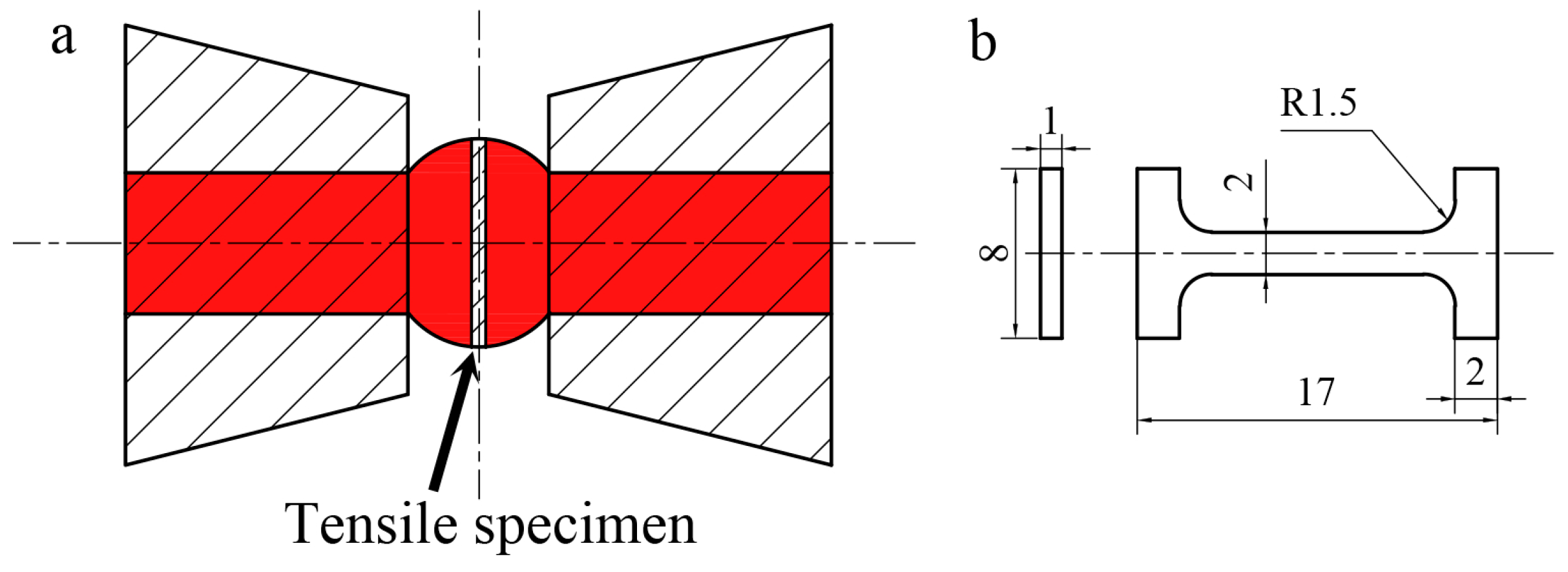
The sampling point and dimensions of the micro-tensile samples are shown in Figure 2. Micro-tensile tests were carried out at room temperature on an Inspekt Table 3 KN model universal testing machine (Hegewald & Peschke, Meß- und Prüftechnik GmbH, Nossen, Germany) with an extension rate of 0.3 mm/min, which fell within the quasi-static tensile range specified in the ASTM standard. The yield strength was determined by an offset stress of 0.2%.
The simulated samples were further processed into standard Charpy V-Notch (CVN) impact samples with a size of 10 × 10 × 55 mm3. The impact properties were examined using a pendulum-instrumented Charpy impact testing machine at a temperature of 20 °C. For minimizing the error, the average impact energy of each steel sample was determined by repeating the impact experiment three times.
The metallographic sample cut from the cross-section of the thermocouple was prepared and etched at a 4% volume of Nital solution and then observed with an axiover-200mat optical microscope (OM) (Carl Zeiss AG, Oberkochen, Germany). The quantitative results of the twins were found using image-pro plus software version 6.0, and at least 10 fields of view were measured for each sample. The grain size could be calculated with the transversal method. The transversal method is a metallographic analysis approach that involves drawing test line segments of known lengths on a metallographic image, counting the number of cross-sectional points where they intersect with the boundaries, and calculating the average grain size by dividing the length of the total segments by the total number of cross-sectional points. Moreover, the misorientation of the samples at the austenite grain boundaries and twin boundaries were analyzed with a Hitachi S-3400 scanning electron microscope (Tokyo, Japan) using electron backscatter diffraction (EBSD), and the fraction of the boundaries could be obtained directly. The metallographic samples were electropolished in a solution of 85% alcohol, 10% perchloric acid, and 5% glycerinum. A JEM-2010 transmission electron microscope (TEM) (JEOL, Tokyo, Japan) was used to characterize the morphology of the dislocations and twins. The TEM samples were obtained by cutting thin slices parallel to the metallographic sections, and a small punch was used to cut discs 3 mm in diameter, which were then thinned via electropolishing. Electropolishing was performed at room temperature and a voltage and current of 25 V and 55–65 mA, respectively, using a 7% perchloric acid/glacial acetic acid mixture. Furthermore, the dislocation density of each sample was obtained using quantitative analysis of X-ray diffraction (XRD). The XRD spectrum was obtained by using a Rigaku D/max-2500/PC diffractometer (Tokyo, Japan) with a scanning angle (2θ) range of 20–100° and a step size of 0.02°.

3. Results

3.1. Mechanical Properties

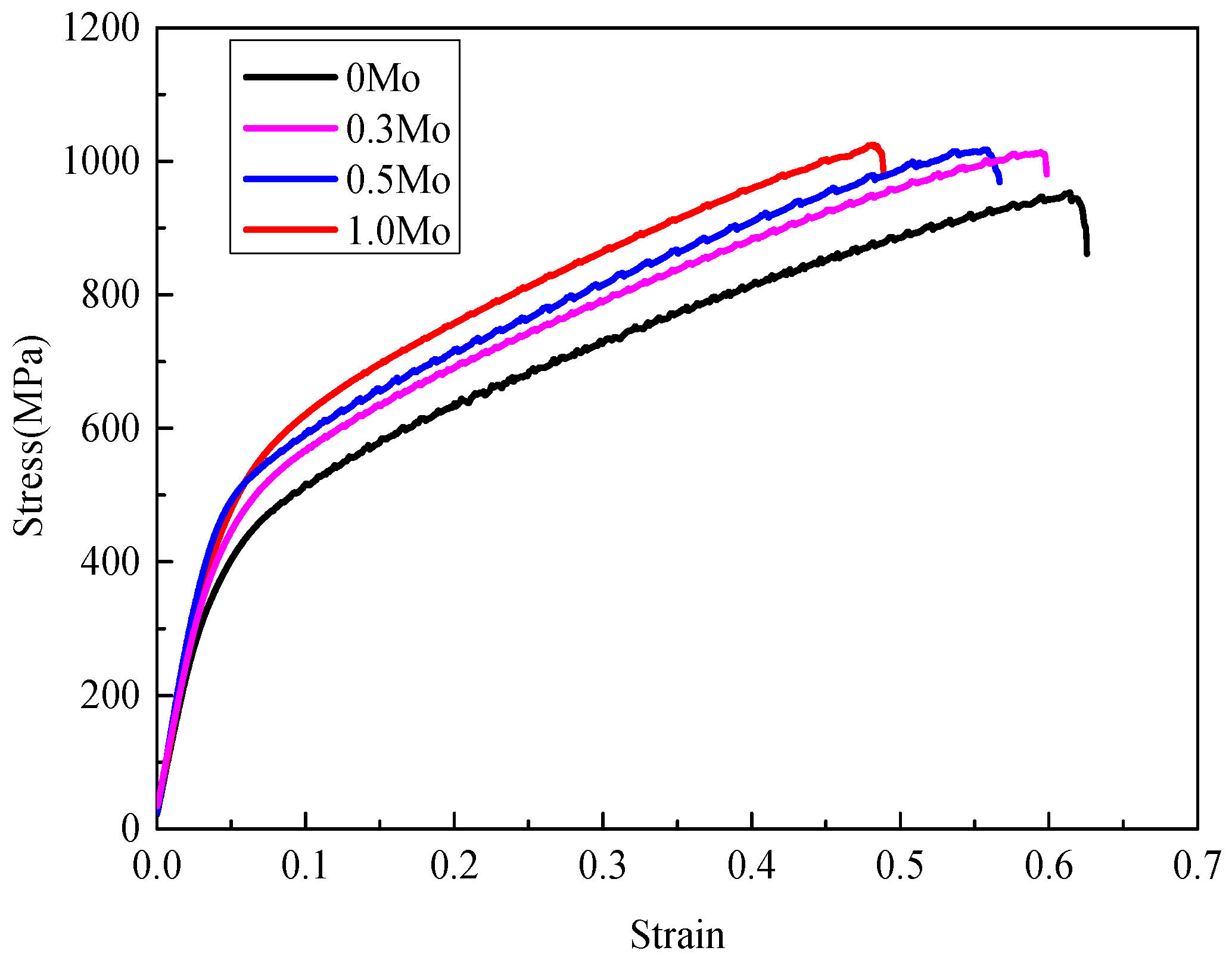
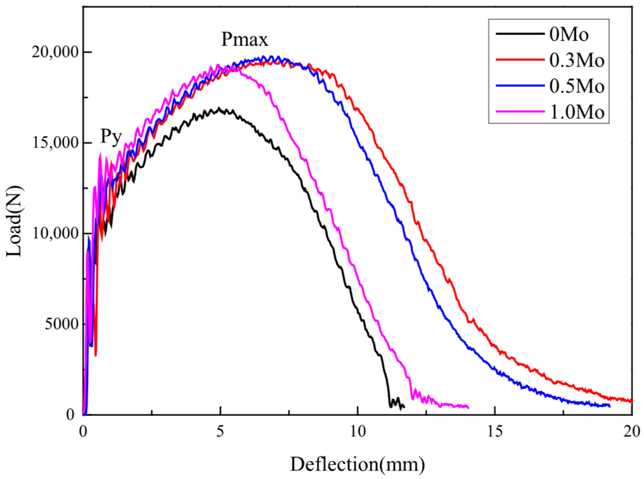
The typical tensile strain–stress curves and load–deflection curves are shown in Figure 3 and Figure 4. The mechanical properties are summarized in Table 2. As the table shows, the tensile strength (TS) increased from 946 to 1023 MPa with the Mo content increasing from 0.02 to 1.01 wt.%, whereas the yield strength (YS) increased significantly from 344 to 415 MPa. Meanwhile, the elongation decreased from 62% to 48%. Moreover, the crack initiation and propagation energy increased from 68 and 70 to 105 and 122 J, respectively, with the Mo content increasing from 0.02 to 0.30 wt.%, and the total impact energy increased from 138 to 227 J. However, when the Mo content further increased from 0.30 to 1.01 wt.%, the crack initiation and propagation energy decreased from 105 and 122 to 78 and 88 J, respectively, and hence the total impact energy decreased from 227 to 166 J.
It can be seen from Figure 3 and Figure 4 that as the Mo content increased from 0 to 1.0%, the general yield load (Py) obtained from the load–deflection curve significantly increased, which was consistent with the changing trend of the yield strength. In addition, the deflection reached its maximum at 0.3%, indicating that a large amount of plastic deformation occurred during the initiation and propagation of impact cracks.

3.2. Microstructure

Figure 5 shows that the metallographic microstructures with different Mo contents were austenite, and the quantified results are shown in Table 3. The high Mn content in the steel significantly expanded the austenite region and resulted in no cooling transformation occurring during the cooling stage. The difference was that as the Mo content increased from 0.02 to 1.01 wt.%, the grain size was refined from 75 to 20 μm. At the same time, there was also significant thinning of the austenite grain boundaries. In addition, as the Mo content increased, the twins running through the entire grain gradually decreased, while those ending within the grain increased. The morphology of the twins evolved from long and strip-shaped to short and rod-shaped.
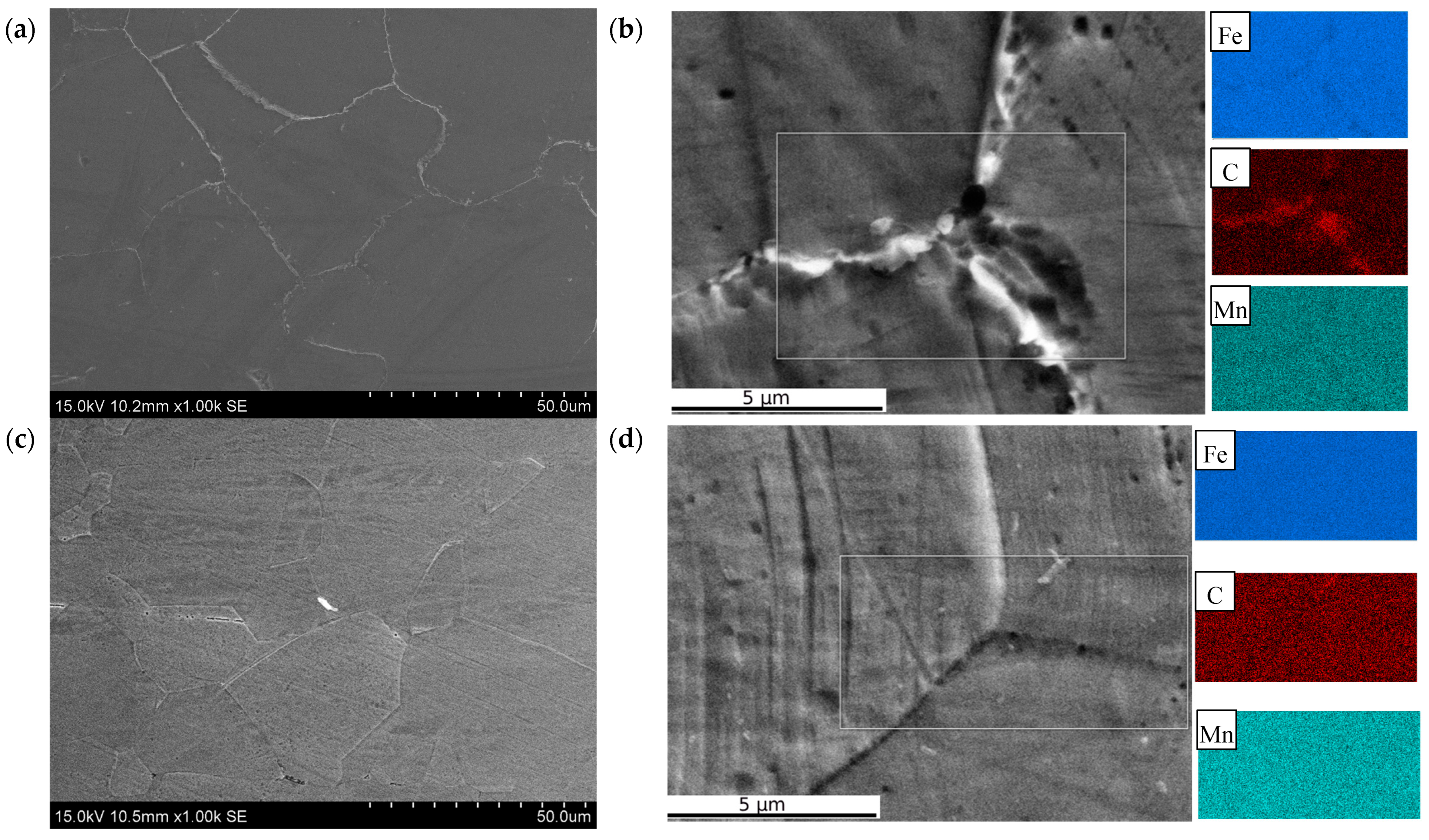
The microstructures observed via SEM of the different Mo content samples are shown in Figure 6. It can be seen that when the Mo content was 0.02 wt.%, a large amount of carbides appeared at the grain boundaries (Figure 6a). The EDS analysis indicated that the grain boundary carbides were formed by the segregation of C (Figure 6b). According to the results of the mapping scanning, it can be considered that the carbide was (Fe,Mn)3C. When the Mo content increased to 0.30 wt.%, the grain boundary carbides were significantly reduced, the degree of segregation of C at the grain boundaries was significantly alleviated, and the austenite grain boundaries became significantly finer (Figure 6d).
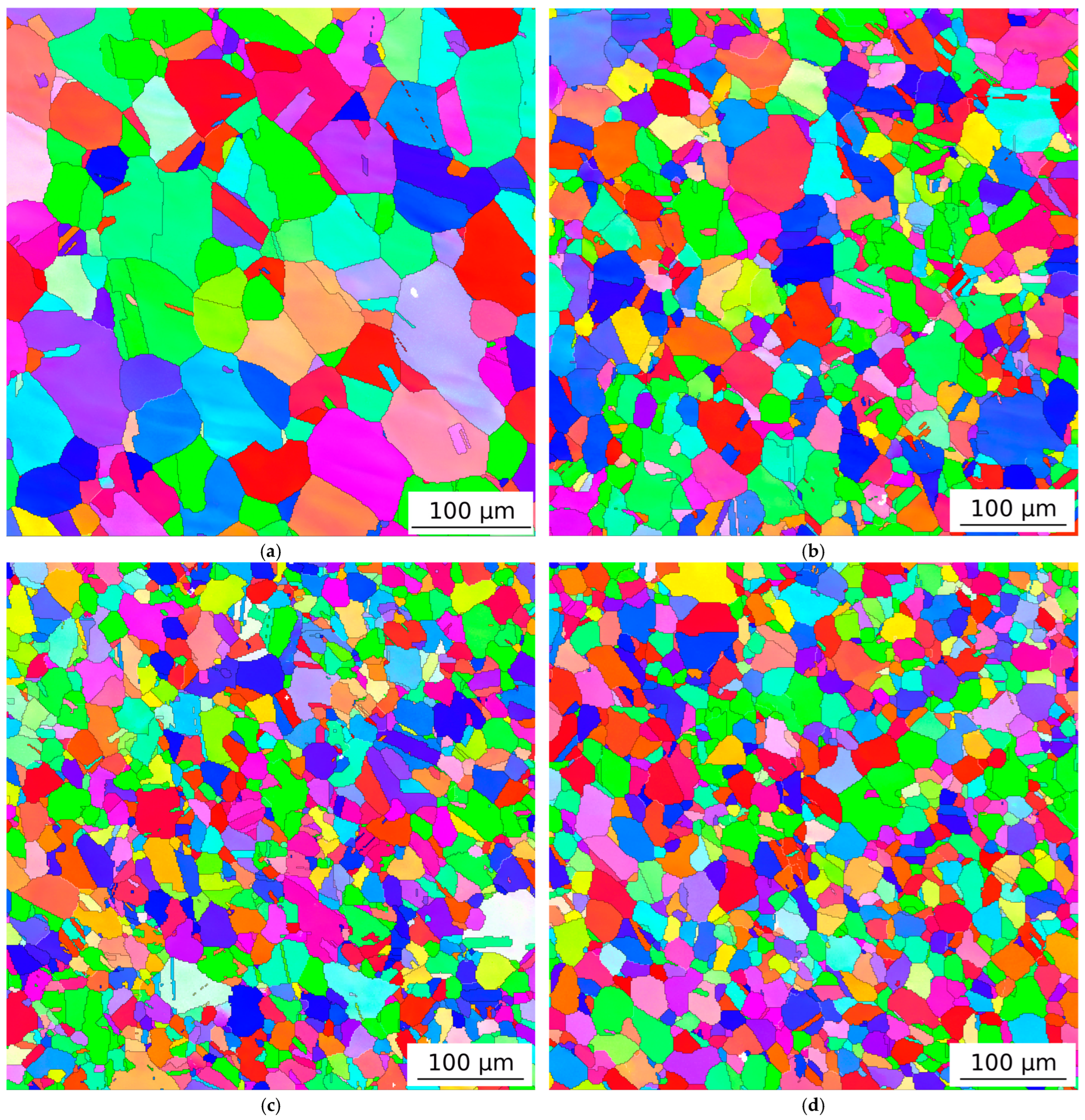
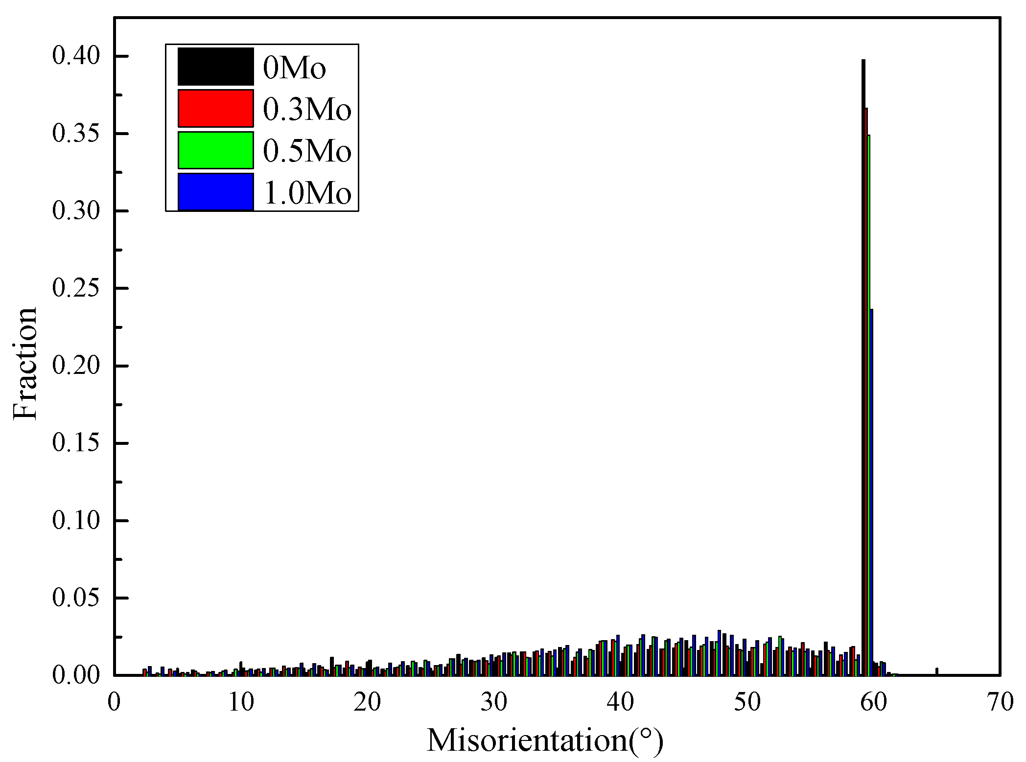
The EBSD inverse pole figures with different Mo contents are shown in Figure 7. With an increase in the Mo content, in addition to significant refinement of the grain size, the morphology of the twins gradually evolved from long, strip-like structures running through the entire grain to short, rod-like structures ending within the grain, and both the size and fraction gradually decreased. The misorientation angles of the austenite boundaries (ABs) and twin boundaries (TBs) were measured, as shown in Table 4. The austenite grain boundaries and the twin boundaries of the four steels were 23.83–52.38° and nearly 60°, respectively, with a crystal direction of <111>. The fraction of different misorientation angles is shown in Figure 8. The range of the grain boundary misorientation angle showed bimodal distributions from 20 to 60° and at 60°, which corresponded to the misorientation angles of the austenite boundaries and twin boundaries, respectively. As shown in Table 3, with an increase in the Mo content, the fraction of austenite grain boundaries increased from 58.05 to 71.51%, while the fraction of twin boundaries decreased from 39.75 to 23.66%.
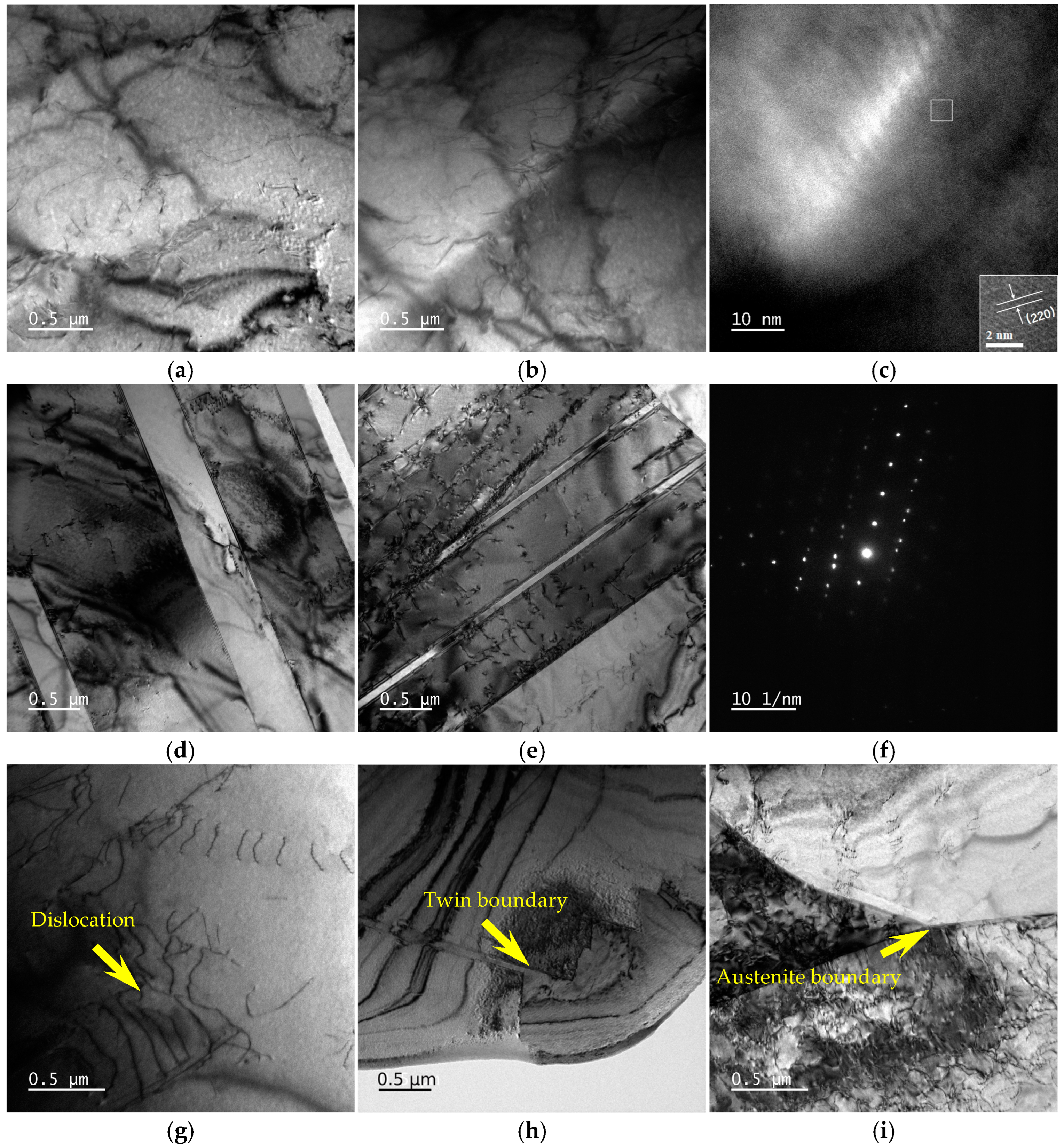
The micro-substructure morphology of the typical Mo content samples under a TEM is shown in Figure 9. As can be seen in Figure 9a–c, there were no obvious precipitated phases on the austenite microstructures of the samples with different Mo contents. After high-resolution treatment, M23C6 could be observed precipitating on the Mo-enhanced samples. As can be seen in Figure 9d–f, with the increase in Mo content, the morphology of the twin evolved from long and strip-like to short and rod-like. Thus, the fraction of the twin boundaries gradually decreased. The diffraction pattern indicated that this subarea was a twin. As can be seen from the dislocation morphologies and the dislocation movement shown in Figure 9g–i, dislocations accumulated at the twin boundaries and austenite grain boundaries, indicating that both twin boundaries and austenite grain boundaries can impede the movement of dislocations.
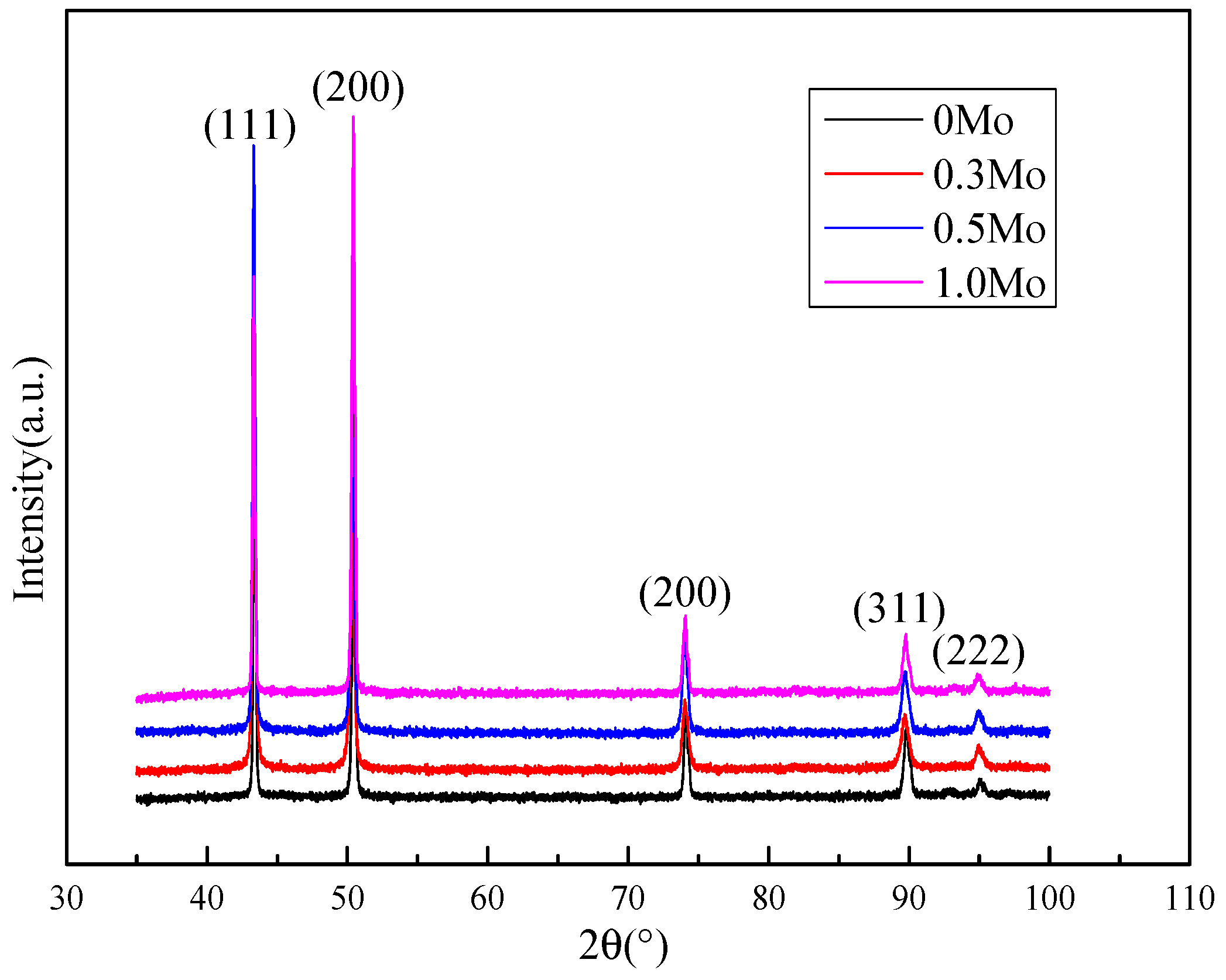
The XRD characteristics of the samples with different Mo contents are shown in Figure 10, indicating that the microstructure of each sample was single-phase austenite. Carbides or precipitates were not detected due to their extremely low contents. The quantification results for the dislocation density are shown in Table 3. With an increase in Mo content, the dislocation density gradually increased, which was due to the mechanism by which Mo inhibited recovery and recrystallization.

3.3. Impact Fracture Characteristics

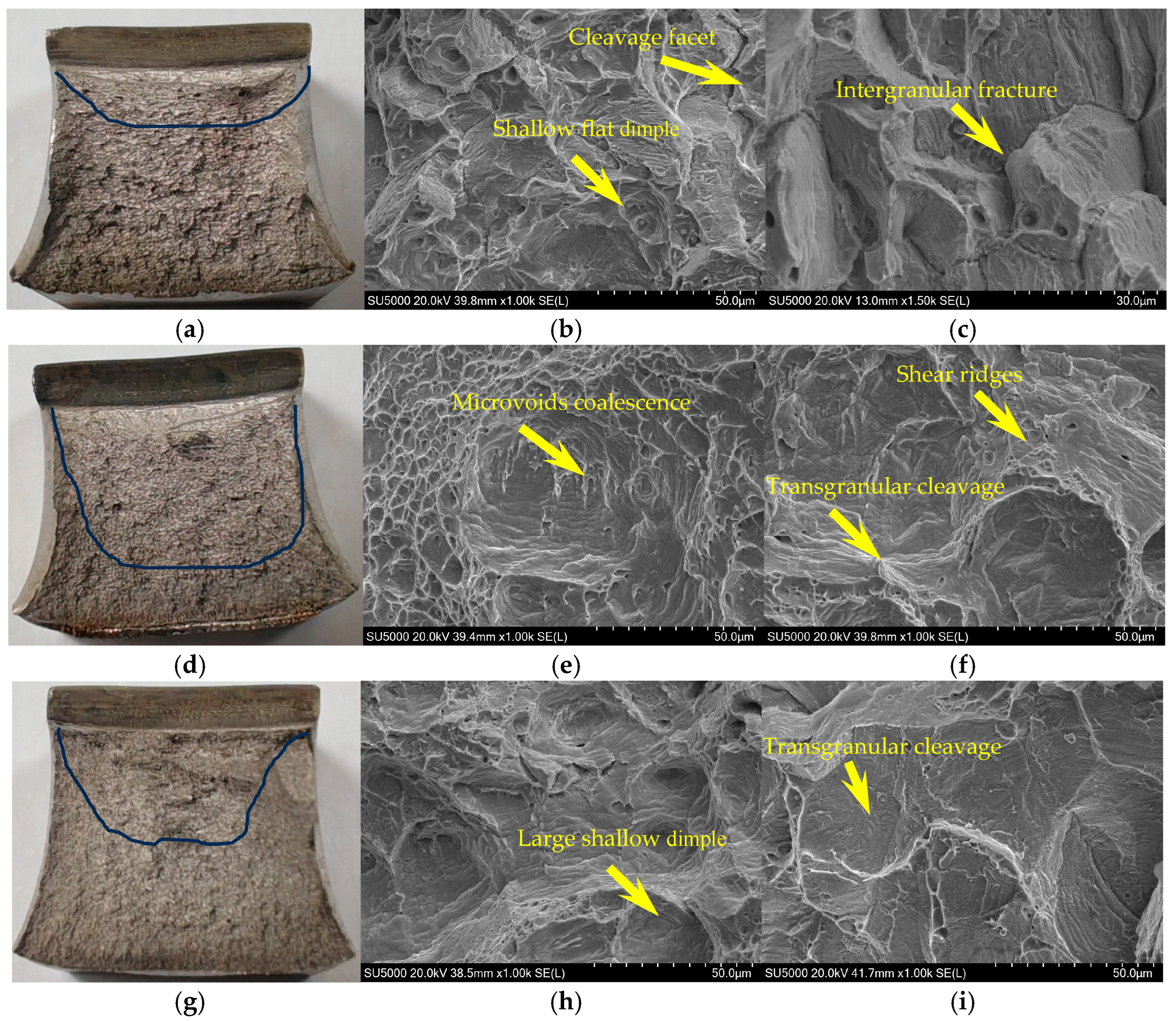
The impact fracture morphologies of the typical Mo content samples under SEM are shown in Figure 11. The percentage of shear fracture areas for the 0Mo, 0.3Mo and 1.0Mo samples was 15%, 77%, and 40%, respectively. As shown in Figure 11b,c, the number of dimples in the ductile zone of the 0Mo sample was rather small, and it presented shallow and flat morphologies. Meanwhile, there was also a large number of cleavage facets in this area. The brittle zone showed a typical intergranular fracture morphology, which was related to the presence of a large amount of carbides at the grain boundaries of the 0Mo sample, resulting in grain boundary embrittlement. As shown in Figure 11e, the ductile zone of the 0.3Mo sample was mainly composed of numerous dimples of different sizes, which were relatively deep and showed a tendency for microvoid coalescence. Figure 11f exhibits a typical transgranular cleavage cracking facet with the river pattern decorated by shear ridges which appeared in the 0.3Mo sample. Moreover, the shear ridge contained tiny dimples, indicating that the crack propagation was hindered by the grain boundaries. These fracture surface morphologies indicate that the main fracture mode changed from a brittle fracture to a ductile fracture, with the Mo content increasing from 0.02 to 0.30 wt.%.
However, as shown in Figure 11h,i, the ductile zone of the 1.0Mo sample was mainly composed of large and shallow dimples, while the brittle zone showed the main cleavage fracture. There were no dimples on the shear ridge, and an intergranular fracture tendency was exhibited, indicating that the grain boundaries were a relatively small hindrance to crack propagation.
The secondary crack morphology of the typical Mo content samples is shown in Figure 12. Under significant deformation, secondary cracks in the 0Mo sample initiated at and expanded along the grain boundaries. This was related to the presence of a large amount of carbides at the grain boundaries of the 0Mo sample, which led to grain boundary embrittlement. In the 0.3Mo sample, multiple microvoids nucleated at the grain boundaries, and adjacent microvoids grew and coalesced, indicating that the overall deformation was distributed to each grain. The 1.0Mo sample simultaneously possessed the characteristics of the 0Mo and 0.3Mo samples. Microcracks initiated at the grain boundaries propagated intergranularly or transgranularly, indicating that the grain boundaries had a limited hindrance toward crack propagation.

4. Discussion

4.1. Effect of Mo Content on Microstructures

As shown in Figure 5 and Figure 9, a single microstructure of austenite with twins formed in each experimental steel sample. With an increased Mo content, the distribution of carbides changed from the grain boundaries to the interior of the grains. Meanwhile, the mean diameter of the austenite grain boundaries decreased, and the area fraction and size of the twins decreased. The evolution of the final microstructure with the increased Mo content can be explained as follows.
In high-manganese steel produced via the TMCP, as the Mo content increased from 0 to 0.3–1.0 wt.%, the distribution of carbides migrated from the grain boundaries to the interior of the grains. This phenomenon was mainly attributed to the effect of Mo on the precipitation behavior of carbides. First, Mo preferentially combined with carbon to form carbides such as M23C6 (Figure 9). These carbides tended to nucleate at intragranular dislocations or substructures rather than at the grain boundaries [31]. Second, Mo aggregated at the grain boundaries, reducing the grain boundary energy and decreasing the driving force for the nucleation of carbides at the grain boundaries. Meanwhile, dislocations, vacancies, and other defects within the grains which formed during rolling became more favorable nucleation sites for carbides [32].
With the Mo content increased from 0 to 0.3–1.0 wt.%, the austenite grain size was significantly refined. This phenomenon was mainly attributed to the inhibitory effect of Mo on the recrystallization behavior of austenite. The radius of the Mo atoms was relatively large (~0.140 nm), and their diffusion rate in austenite was low. They tended to aggregate at the grain boundaries, hindering the migration of grain boundaries. In addition, the Mo and C formed M23C6 carbides, pinning the grain boundary. Therefore, the solute atoms’ dragging effect of Mo and the carbides’ pinning effect worked together to inhibit the recrystallization behavior of austenite and refined the austenite grains [28]. In addition, with the increase in Mo content, the dislocation density significantly increased, providing a large number of nucleation sites for the recrystallization process.
It can be seen in Figure 5 that with an increase in Mo content, in addition to significant refinement of the austenite grain size, the size of the twins was refined, and the fraction decreased, consistent with the gradual reduction in the fraction of twin boundaries (Figure 8). It is generally acknowledged that Mo can reduce the stacking fault energy, which is conducive to the nucleation of twins and thereby increases the fraction of twins [16]. In this high-manganese steel produced via the TMCP, the inhibitory effect of Mo on the recrystallization behavior of austenite, on the one hand, led to significant refinement of the austenite grain size, and on the other hand, it also inhibited the migration of twin boundaries, hindered the growth of twins, and had a refinement effect on the size of the twins [28]. In addition, Mo was concentrated at the high-angle grain boundaries of austenite, reducing the grain boundary energy and inhibiting the formation of coherent twin grain boundaries [29,33]. These tiny twins could not separate the austenite grains and had a limited effect on refining the entire microstructure.

4.2. Effect of Mo Content on Tensile Properties

The microstructures of the experimental steels determine the mechanical properties, but the contribution of the microstructure and sub-microstructure to the yield strength in high-manganese steel produced with the TMCP has not been systematically studied. The strengthening mechanisms in high-manganese steel mainly include grain boundary strengthening, dislocation strengthening, solid solution strengthening, and precipitation strengthening [34]. According to the strengthening model, the yield strength of the experimental steel can be expressed as follows:
σy = σA + σb + σd + σs + σp
where σA is the lattice strengthening, σb is the grain boundary strengthening, owing to the grain size, σd is the dislocation strengthening, σs is the solid solution strengthening, and σp is the precipitation strengthening, expressed with the MPa unit of strength. The contributions of different strengthening methods to the yield strength are discussed in detail.
Lattice friction stress is the force that hinders the movement of dislocations in the lattice and is related to the crystal structure [34]. For this study, the lattice friction stress is related to the shear modulus of austenite and can be calculated according to the following formula [34]:
σA = 31/2 τ0
τ0 = 2 × 10⁻⁴ G
where σA is the lattice strengthening, τ0 is the shear stress due to dislocation movement, owing to the shear modulus, and G is the shear modulus, expressed in GPa. For the austenitic steels, the value of G was 68 GPa [35]. The lattice friction stress of the experimental steels was calculated to be 24 MPa.
Theoretically speaking, the finer the grains, the higher the strength of the metal material. This is because the smaller the grain size, the more grain boundaries are contained within the microstructure. When deformation occurs, the grain boundaries can act as obstacles for dislocation sliding during the plastic deformation of the material, causing dislocations to accumulate at the grain boundaries. To further cause plastic deformation of the material, the external force must be increased to enhance the strength. The Hall–Petch equation was used to calculate the contribution of grain boundary strengthening [36]:
σy = σ0 + k d−1/2
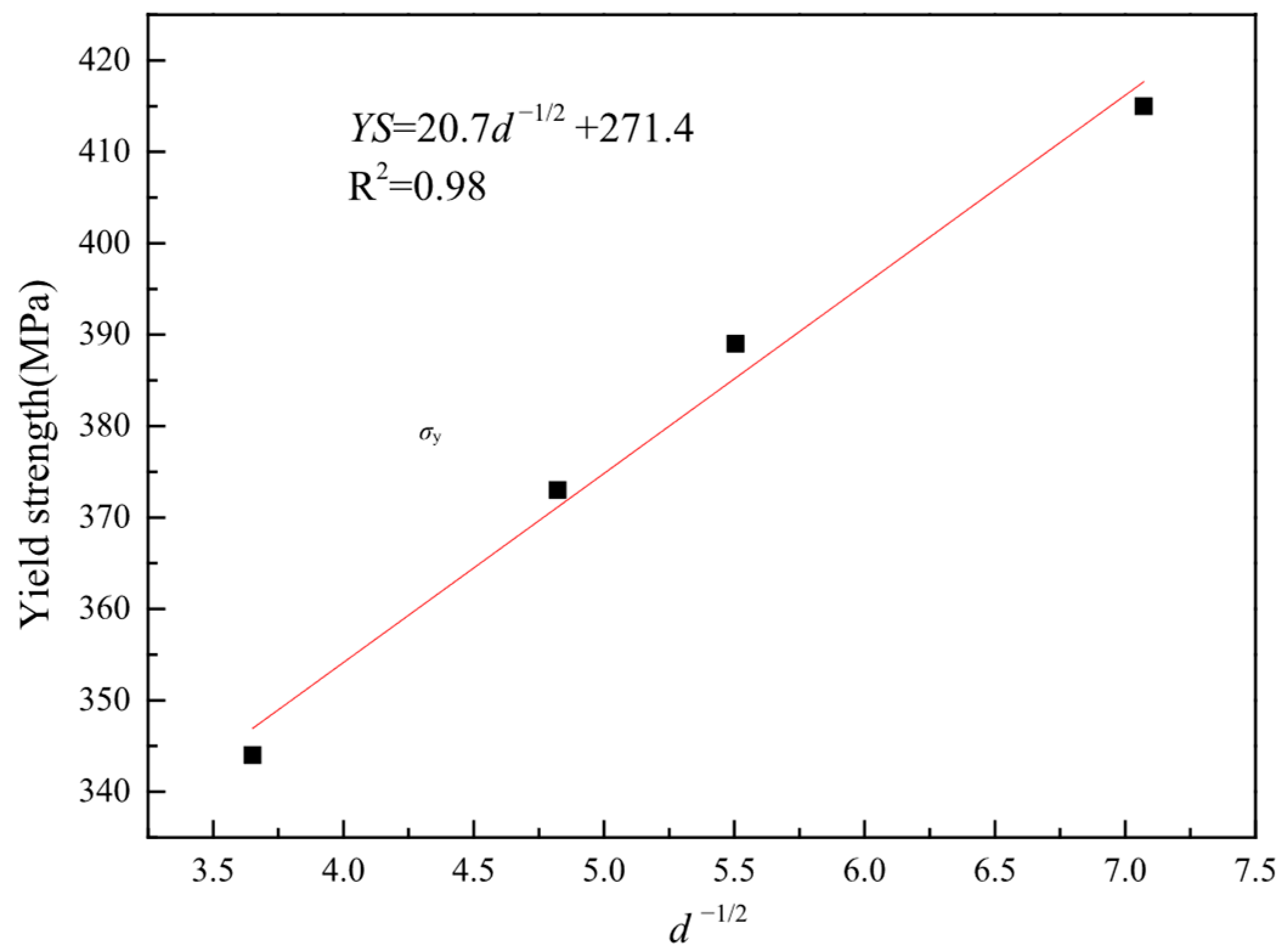
For this purpose, this study established a relationship between the yield strength and grain size (d, in μm), and a correlation coefficient of 0.96 was obtained, as shown in Figure 13. The corresponding linear regression equation is given by
σb = 271.4 + 20.7 d−1/2
The contribution from boundary strengthening of each steel sample is summarized in Table 5. As the table shows, grain boundary strengthening’s contribution increased with increasing Mo contents, owing to the decreasing grain size of the austenite and twins.
During the plastic deformation of metals, dislocations slip, generating a series of interactions that cause dislocations to entwine with each other, making dislocation slip difficult and plastic deformation hard to carry out, thereby enhancing the strength of the metals. The contribution of dislocation strengthening (σd) to the YS can be estimated with the following equation [37]:
σd = αMGbρ1/2
where α is the geometrical factor, M is the Taylor factor, G is the shear modulus in GPa, b is the Burgers vector in nm, and ρ is dislocation density in m−2. In the equation, for the experimental steels with different Mo contents whose matrix microstructures were austenite, the values of α, M, G, and b were 0.136, 3.06, 68 GPa, and 0.254 nm, respectively [38]. The dislocation strengthening contribution could be obtained with the above calculation method, as shown in Table 5.
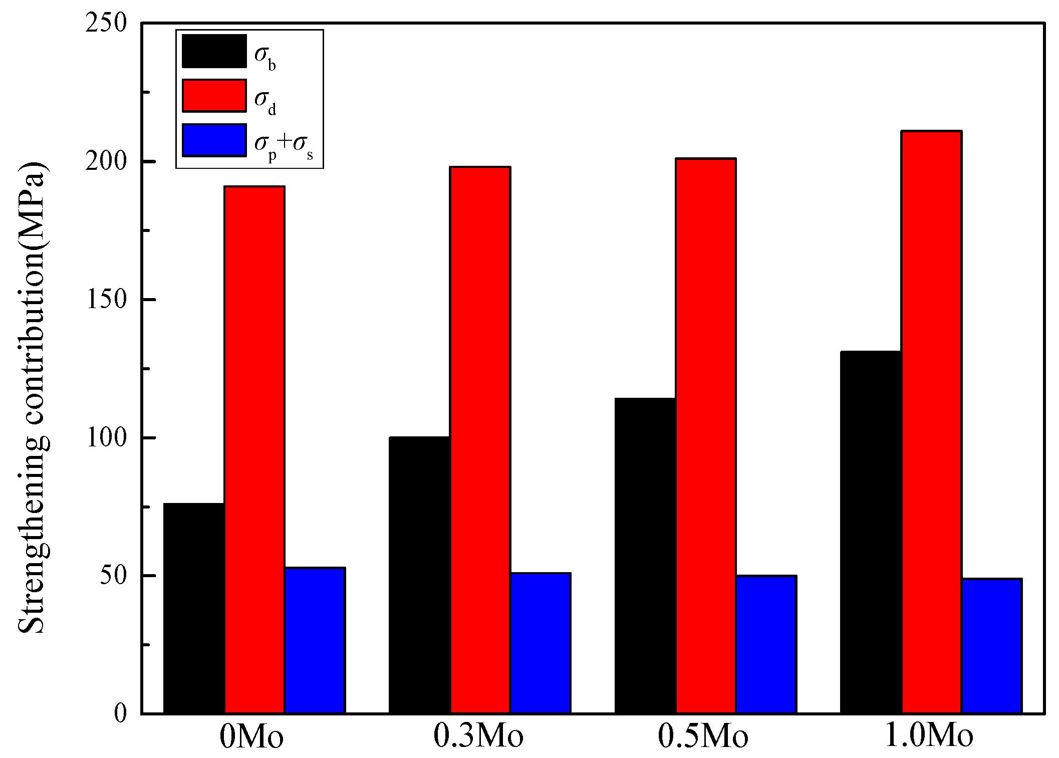
In addition to the aforementioned strengthening mechanisms, the sum of other individual strengthening contributions, σs + σp, was approximately the same for all the steels considered (Table 5). The increased Mo content led to decreases in the grain size and increases in the dislocation density, which in turn may result in enhanced strengthening contributions. However, due to the control range of the Mo content being at a relatively low level of 0~1.0 wt.%, the precipitates were not obvious, and the solid solution of Mo was relatively low, resulting in no significant changes in precipitation strengthening or solid solution strengthening. As a result, the overall YS increased with increasing Mo contents.
The individual factors may be written in descending order based on their strengthening contributions in terms of dislocations, grain size, solid solution, and precipitates. The contributions of various strengthening factors to the yield strength are shown in Table 5, and the regular trends are presented in Figure 14. It can be seen that regardless of the Mo content, the contribution of dislocation strengthening to the yield strength was 51~56%, indicating that dislocation strengthening brought about by rolling was the most significant strengthening method in the high-manganese steel. With an increase in the Mo content from 0.02 to 1.01 wt.%, grain boundary strengthening and dislocation strengthening gradually increased, while solid solution strengthening and precipitation strengthening had little effect. Aside from leading to an increase in yield strength, they also brought about an increase in tensile strength.
In the austenitic high-manganese steel produced with the TMCP, on the one hand, as Mo reduced the stacking fault energy [16], with an increase in Mo content, the deformation mechanism during the tensile process changed from twin and slip to dislocation slip dominance. On the other hand, an increase in Mo content led to a decrease in the twin content and a reduction in the strain hardening capacity. In addition, during the slip process of dislocations, as the Mo increased, the number of grain boundaries and precipitates that hindered the slipping of dislocations also increased, resulting in the obstruction of dislocation slip and a decrease in elongation.

4.3. Effect of Mo Content on Impact Properties

Based on the impact properties in Figure 4 and Table 2, it can be seen that the impact energy showed a trend of first increasing and then decreasing. The total impact energy increased from 138 to 227 J with the Mo content increasing from 0.02 to 0.30 wt.%. However, the Mo content was further increased from 0.30 to 1.01 wt.%, and the total impact energy decreased from 227 to 166 J. The impact energy reached the highest point when the Mo content was 0.30 wt.%.
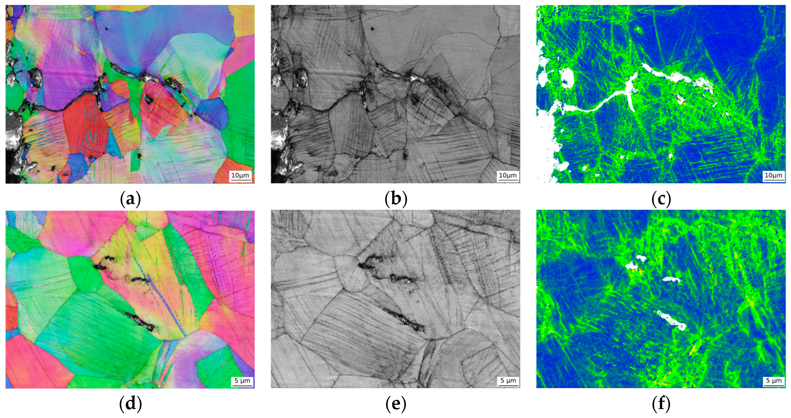
Figure 15 shows the secondary crack propagation and stress distribution of two typical fracture modes. As can be seen in Figure 6, the grain boundaries of the 0Mo sample contained a large amount of carbides. Under large deformations, the stress concentration at the grain boundaries was significant (Figure 15c), and cracks were highly likely to initiate from the carbides on the grain boundaries and propagate along them. Therefore, based on the macroscopic fracture surface, the fracture morphology was mainly intergranular fractures. As the Mo content increased from 0.02 to 0.30 wt.%, the phenomenon of carbide segregation at the grain boundaries was greatly alleviated. Under large deformations, a large number of deformation bands formed inside the grains. The deformation within the grains and at the grain boundaries was uneven, and microvoids were initiated at the grain boundaries. Moreover, the size of the austenite grains was significantly refined, and the twin boundaries could also act as obstacles to prevent crack propagation (Figure 15d).
Intergranular carbides are usually harder and more brittle than the matrix [39]. Under impact loads, significant stress concentration occurs between these hard, brittle phases and the relatively soft matrix, as well as at the corners of the carbides themselves, which become the preferred locations for crack initiation [40]. Intergranular carbides weaken the bonding force at grain boundaries [41]. Continuous or semi-continuous intergranular carbide films can sever the atomic bonds of grains on both sides of the grain boundaries, disrupt the continuity of the matrix, and reduce the bonding strength at the grain boundaries [41,42]. Once cracks initiate at the intergranular carbide sites, they tend to propagate along the path with the weakest bonding force. The grain boundaries weakened by carbides precisely provide such a low-energy propagation path, causing cracks to propagate along the grain boundaries and form intergranular fracture morphologies [39,41].
In the high-manganese austenitic steel, as the Mo content increased from 0.3 to 1.0 wt.%, the austenite grain size was further refined, the twin fraction and twin boundaries decreased, the dislocation density increased, and the grain refinement led to an increase in strength, but the impact toughness decreased. As can be seen in Figure 12, the grain boundaries were usually the crack initiation sites. Secondary cracks or microvoids initiated from the austenite grain boundaries, indicating that stress concentration was prone to occur at the austenite grain boundaries. With an increase in Mo content, the dislocation density after hot rolling became greater, and the dislocation accumulation became more severe, which intensified the initiation of secondary cracks or microvoids at the grain boundaries and reduced the crack initiation energy. As can be seen in Figure 15d, the secondary crack of the increased-Mo specimen stopped after encountering the twin boundary during the propagation process, indicating that the twin boundary can hinder crack propagation. With an increase in Mo content, the twin boundaries decreased, and the hindrance capacity for crack propagation weakened, resulting in a decrease in the crack propagation energy.

5. Conclusions

For high-manganese railway frog steel produced via the TMCP, the influence of the Mo content on the microstructure and mechanical properties was researched, and the conclusions are as follows:
(1)
A single austenite formed in each Mo-containing steel. With an increased Mo content, the grain boundary carbides decreased due to the formation of carbides within the grains, and the austenite and twin sizes were refined due to the dragging effect of the solute atoms of Mo and the pinning effect of the precipitates.
(2)
With an increase in Mo content, grain boundary strengthening and dislocation strengthening increased, while solid solution strengthening and precipitation strengthening had little effect, leading to an increase in the final yield strength. The contribution of dislocation strengthening to the yield strength was 51~56%, indicating that dislocation strengthening was the most significant strengthening method in the high-manganese steel.
(3)
The impact energy showed a trend of first increasing and then decreasing, and the impact energy reached the highest point when the Mo content was 0.30 wt.%. This was caused by the combined regulation of the grain boundary carbides, austenite, and twin boundaries.
(4)
From the perspective of the results and analysis of the microstructure and properties, considering the requirement of a low alloy cost, for the hot-rolled high-manganese austenitic steel, the optimal control target for the Mo content is 0.30 wt.%.

Author Contributions

Conceptualization, J.L. and G.S.; methodology, T.T.; validation, X.F., P.W. and Q.W.; formal analysis, G.S. and P.W.; investigation, X.F.; data curation, T.T.; writing—original draft preparation, J.L.; writing—review and editing, Q.W.; project administration, Q.W.; funding acquisition, Q.W. All authors have read and agreed to the published version of the manuscript.

Funding

This research received no external funding.

Data Availability Statement

The original contributions presented in this study are included in the article. Further inquiries can be directed to the corresponding author.

Conflicts of Interest

Author Junke Lin was employed by the company China Railway Engineering Equipment Group Co., Ltd. Author Tiebing Tang was employed by the company China Railway Shanhaiguan Bridge Group Co., Ltd. The remaining authors declare that the research was conducted in the absence of any commercial or financial relationships that could be construed as a potential conflict of interest.

References

  1. Schilke, M.; Ahlström, J.; Karlsson, B. Low Cycle Fatigue and Deformation Behaviour of Austenitic Manganese Steel in Rolled and in As-Cast Conditions. Procedia Eng. 2010, 2, 623–628. [Google Scholar] [CrossRef]
  2. Wu, T.-Y.; Ieong, H.I.; Hsu, W.-L.; Chang, C.-M.; Lai, Y.-C. Assessment of Fatigue Crack Growth in Metro Cast Manganese Steel Frogs and Inspection Strategy. Eng. Fail. Anal. 2024, 163, 108512. [Google Scholar] [CrossRef]
  3. Falodun, O.E.; Oke, S.R.; Okoro, A.M.; Olubambi, P.A. Characterization of Cast Manganese Steels Containing Varying Manganese and Chromium Additions. Mater. Today Proc. 2020, 28, 730–733. [Google Scholar] [CrossRef]
  4. Qian, L.; Cui, X.; Li, D.; Liu, S.; Meng, J.; Zhang, F.; Xie, H. Cyclic Deformation Fields Interactions between Pores in Cast High Manganese Steel. Int. J. Plast. 2019, 112, 18–35. [Google Scholar] [CrossRef]
  5. Sabzi, M.; Farzam, M. Hadfield Manganese Austenitic Steel: A Review of Manufacturing Processes and Properties. Mater. Res. Express 2019, 6, 1065c2. [Google Scholar] [CrossRef]
  6. Han, J.; Luo, S.; Liu, N.; Chen, K.; Xie, S.; Wang, W.; Zhu, M. Experimental Investigation on Effect of Cooling Rate on Carbide Precipitation during Solidification of High Manganese Steel. J. Mater. Res. Technol. 2024, 33, 1075–1086. [Google Scholar] [CrossRef]
  7. Liu, E.; Wu, W.; Zhao, Y.; Tan, X.; Nie, S.; Yan, Q.; Xia, M.; Guo, H.; He, M.; Ge, C. Tailoring Precipitation Behavior of Carbonitrides in High Manganese-Aluminum Steels via Microalloying Elements. J. Mater. Res. Technol. 2025, 36, 6050–6061. [Google Scholar] [CrossRef]
  8. Yang, H.; Fang, C.; Zhao, E.; Liu, H.; Liu, H.; Hao, J.; Peng, Y.; Yi, H. Wear-Resistant High Manganese Steel/WC Composite Coatings with Twinning-Induced Hardening Ability Prepared by Laser Cladding. Wear 2025, 580–581, 206250. [Google Scholar] [CrossRef]
  9. Sui, F.; Wang, X.; Zhao, J.; Ma, B.; Li, C. Analysis on Shear Deformation for High Manganese Austenite Steel during Hot Asymmetrical Rolling Process Using Finite Element Method. J. Iron Steel Res. Int. 2015, 22, 990–995. [Google Scholar] [CrossRef]
  10. Xu, D.; Zhang, D.; Yang, G.; Wang, Q.; Bao, S.; Zhao, G. Effect of Quenching Temperature on the Austenite Stability and Mechanical Properties of High-Strength Air-Cooled TRIP Steel Prepared with Hot-Rolled C–Si–Mn Sheets. J. Mater. Res. Technol. 2024, 31, 420–433. [Google Scholar] [CrossRef]
  11. Mishra, G.; Chandan, A.K.; Kundu, S. Hot Rolled and Cold Rolled Medium Manganese Steel: Mechanical Properties and Microstructure. Mater. Sci. Eng. A 2017, 701, 319–327. [Google Scholar] [CrossRef]
  12. Cazac, A.-M.; Chelariu, R.G.; Cimpoesu, R.; Bernevig, M.A.; Benchea, M.; Jurca, A.M.; Radu, A.M.; Vasilescu, G.D.; Garaliu-Busoi, B.; Lupu, F.C.; et al. Investigation of CuTi Alloy for Applications as Non-Sparking Material. Appl. Sci. 2024, 14, 11574. [Google Scholar] [CrossRef]
  13. Lupu, F.C.; Munteanu, C.; Istrate, B. Improvement of the Mechanical and Microstructural Properties of the Materials Used for Armour by Surface Deposition Using the Cold Spray Method. INCAS Bull. 2024, 16, 73–80. [Google Scholar] [CrossRef]
  14. Hu, Q.; Du, H.; Sun, X.; Hou, L.; Wang, Q.; Guo, Z.; Li, H.; Fan, J.; Wei, Y.; Liu, X.; et al. Effect of Mo on the σ-Phase Precipitation Behavior of Super-Austenitic Stainless Steel. Emerg. Mater. Res. 2024, 13, 141–151. [Google Scholar] [CrossRef]
  15. Liu, C.; Sun, J.; Lu, S. Precipitation Behavior and Mechanical Properties of 16Cr–25Ni Austenitic Stainless Steel Weld Metals with Different Mo Content during Aging. J. Mater. Sci. Technol. 2026, 241, 1–17. [Google Scholar] [CrossRef]
  16. Chen, Z.; Zhu, H.; Cao, Y.; Liu, H.; Zhao, Z.; Chen, X.; Li, D. Revisiting the Effect of Localized Alloying Elements on Stacking Fault Energy in Austenitic Steel. Mater. Sci. Eng. A 2025, 929, 148074. [Google Scholar] [CrossRef]
  17. Hua, M.; Chen, C.; Lin, W.; Ming, X.; Guoji, C.; Fucheng, Z. Effect of Mo Alloying on Wear Behavior of Hadfield Steel. J. Mech. Eng. 2020, 56, 81. [Google Scholar] [CrossRef]
  18. Qiu, X.; Wang, Y.; Yang, B.; Xiong, Z.; Cheng, X. Multiphase Precipitation Behavior and Tensile Properties of a Fe-Mn-Al-Mo-C Austenitic Lightweight Steel. Mater. Sci. Eng. A 2023, 885, 145654. [Google Scholar] [CrossRef]
  19. Zhao, Y.; Cao, Y.; Wen, W.; Lu, Z.; Zhang, J.; Liu, Y.; Chen, P. Effects of Mn Content on Austenite Stability and Mechanical Properties of Low Ni Alumina-Forming Austenitic Heat-Resistant Steel: A First-Principles Study. Sci. Rep. 2023, 13, 5769. [Google Scholar] [CrossRef]
  20. Moon, J.; Kim, S.-D.; Lee, C.-H.; Jo, H.-H.; Hong, H.-U.; Chung, J.-H.; Lee, B.H. Strengthening Mechanisms of Solid Solution and Precipitation at Elevated Temperature in Fire-Resistant Steels and the Effects of Mo and Nb Addition. J. Mater. Res. Technol. 2021, 15, 5095–5105. [Google Scholar] [CrossRef]
  21. Huang, J.; Bahador, A.; Kondoh, K. Microstructure Development and Strengthening Behaviour in Hot-Extruded Ti-Mo Alloys with Exceptional Strength-Ductility Balance. J. Alloys Compd. 2025, 1010, 177195. [Google Scholar] [CrossRef]
  22. Liu, C.; Xiong, F.; Wang, Y.; Cao, Y.; Liu, X.; Xue, Z.; Peng, Q.; Peng, L. Strengthening Mechanism and Carbide Precipitation Behavior of Nb-Mo Microalloy Medium Mn Steel. Materials 2021, 14, 7461. [Google Scholar] [CrossRef]
  23. Lee, J.; Kim, H.; Park, S.-J.; Moon, J.; Han, H.N. Correlation between Macroscale Tensile Properties and Small-Scale Intrinsic Mechanical Behavior of Mo-Added Fe–Mn–Al–C Lightweight Steels. Mater. Sci. Eng. A 2019, 768, 138460. [Google Scholar] [CrossRef]
  24. Han, R.; Yang, G.; Xu, D.; Jiang, L.; Fu, Z.; Zhao, G. Effect of V on the Precipitation Behavior of Ti−Mo Microalloyed High-Strength Steel. Materials 2022, 15, 5965. [Google Scholar] [CrossRef]
  25. Cui, G.; Liu, H.; Li, S.; Gao, G.; Hassani, M.; Kou, Z. Effect of Ni, W and Mo on the Microstructure, Phases and High-Temperature Sliding Wear Performance of CoCr Matrix Alloys. Sci. Technol. Adv. Mater. 2020, 21, 229–241. [Google Scholar] [CrossRef] [PubMed]
  26. Moon, J.; Park, S.-J.; Jang, J.H.; Lee, T.-H.; Lee, C.-H.; Hong, H.-U.; Han, H.N.; Lee, J.; Lee, B.H.; Lee, C. Investigations of the Microstructure Evolution and Tensile Deformation Behavior of Austenitic Fe-Mn-Al-C Lightweight Steels and the Effect of Mo Addition. Acta Mater. 2018, 147, 226–235. [Google Scholar] [CrossRef]
  27. Moon, J.; Ha, H.-Y.; Park, S.-J.; Lee, T.-H.; Jang, J.H.; Lee, C.-H.; Han, H.N.; Hong, H.-U. Effect of Mo and Cr Additions on the Microstructure, Mechanical Properties and Pitting Corrosion Resistance of Austenitic Fe-30Mn-10.5Al-1.1C Lightweight Steels. J. Alloys Compd. 2019, 775, 1136–1146. [Google Scholar] [CrossRef]
  28. Sairam, K.; Phaniraj, M.P.; Rajesh, K. Effect of Molybdenum on Recrystallization Behavior of Fe30Mn5Al1C- x Mo Lightweight Austenitic Steels. Scr. Mater. 2023, 230, 115399. [Google Scholar] [CrossRef]
  29. Shi, Y.B.; Zhou, G.Y.; Cao, G.H.; Zhang, H.; Liu, C.S.; Dong, X.M.; Zhang, Z.H. Effect of Nb and Mo Microalloying on Sulfide Stress Cracking Resistance and Hydrogen Permeation Behavior of Advanced Casing Steel. Int. J. Hydrogen Energy 2025, 161, 150583. [Google Scholar] [CrossRef]
  30. ASTM A128/A128M-21; Standard Specification for Steel Castings, Austenitic Manganese. ASTM International: West Conshohocken, PA, USA, 2021.
  31. Chen, Z.; Miao, S.; Kong, L.; Wei, X.; Zhang, F.; Yu, H. Effect of Mo Concentration on the Microstructure Evolution and Properties of High Boron Cast Steel. Materials 2020, 13, 975. [Google Scholar] [CrossRef]
  32. Gao, Y.; Zhang, M.; Li, J.; Wang, R.; Yuan, Z.; Tan, Z.; Yu, W. Precipitation Mechanisms and Crystallographic Study of Co-Precipitation Carbides in Super Austenitic Stainless Steel. J. Alloys Compd. 2025, 1036, 181942. [Google Scholar] [CrossRef]
  33. Wang, Y.; Xiao, B.; Liang, X.; Peng, H.; Zhou, J.; Lin, F. Strengthened Microstructure and Mechanical Properties of Austenitic 316L Stainless Steels by Grain Refinement and Solute Segregation. J. Mater. Res. Technol. 2025, 34, 552–565. [Google Scholar] [CrossRef]
  34. Kusakin, P.; Belyakov, A.; Molodov, D.A.; Kaibyshev, R. On the Effect of Chemical Composition on Yield Strength of TWIP Steels. Mater. Sci. Eng. A 2017, 687, 82–84. [Google Scholar] [CrossRef]
  35. Croft, S. Kaye and Laby—Tables of Physical and Chemical Constants (15th Edn). Phys. Bull. 1987, 38, 149. [Google Scholar] [CrossRef]
  36. Hansen, N. Hall–Petch Relation and Boundary Strengthening. Scr. Mater. 2004, 51, 801–806. [Google Scholar] [CrossRef]
  37. Liang, Z.Y.; Li, Y.Z.; Huang, M.X. The Respective Hardening Contributions of Dislocations and Twins to the Flow Stress of a Twinning-Induced Plasticity Steel. Scr. Mater. 2016, 112, 28–31. [Google Scholar] [CrossRef]
  38. Bouaziz, O.; Guelton, N. Modelling of TWIP Effect on Work-Hardening. Mater. Sci. Eng. A 2001, 319–321, 246–249. [Google Scholar] [CrossRef]
  39. Liu, J.; Li, L.; Yang, S.; Ding, C.; Wang, E.; Yu, X.; Wu, H.; Niu, G. Effect of Intragranular κ Carbides and Intergranular Precipitates on the Hot Deformation Mechanism and Dynamic Recrystallization Mechanism of Fe–28Mn–11Al–1.5C–5Cr Lightweight Steel. J. Mater. Res. Technol. 2023, 27, 2346–2362. [Google Scholar] [CrossRef]
  40. Elkot, M.N.; Sun, B.; Zhou, X.; Ponge, D.; Raabe, D. Hydrogen-Assisted Decohesion Associated with Nanosized Grain Boundary κ-Carbides in a High-Mn Lightweight Steel. Acta Mater. 2022, 241, 118392. [Google Scholar] [CrossRef]
  41. Hong, S.; Lee, J.; Lee, B.-J.; Kim, H.S.; Kim, S.-K.; Chin, K.-G.; Lee, S. Effects of Intergranular Carbide Precipitation on Delayed Fracture Behavior in Three TWinning Induced Plasticity (TWIP) Steels. Mater. Sci. Eng. A 2013, 587, 85–99. [Google Scholar] [CrossRef]
  42. Du, H.; Hu, Q.; Yue, X.; Jia, J.; Wei, Y.; Hou, L.; Luo, H.; Wang, Q.; He, H.; Wei, H.; et al. Effect of Mo on Intergranular Corrosion Behavior in Super-Austenitic Stainless Steel. Corros. Sci. 2024, 231, 111986. [Google Scholar] [CrossRef]
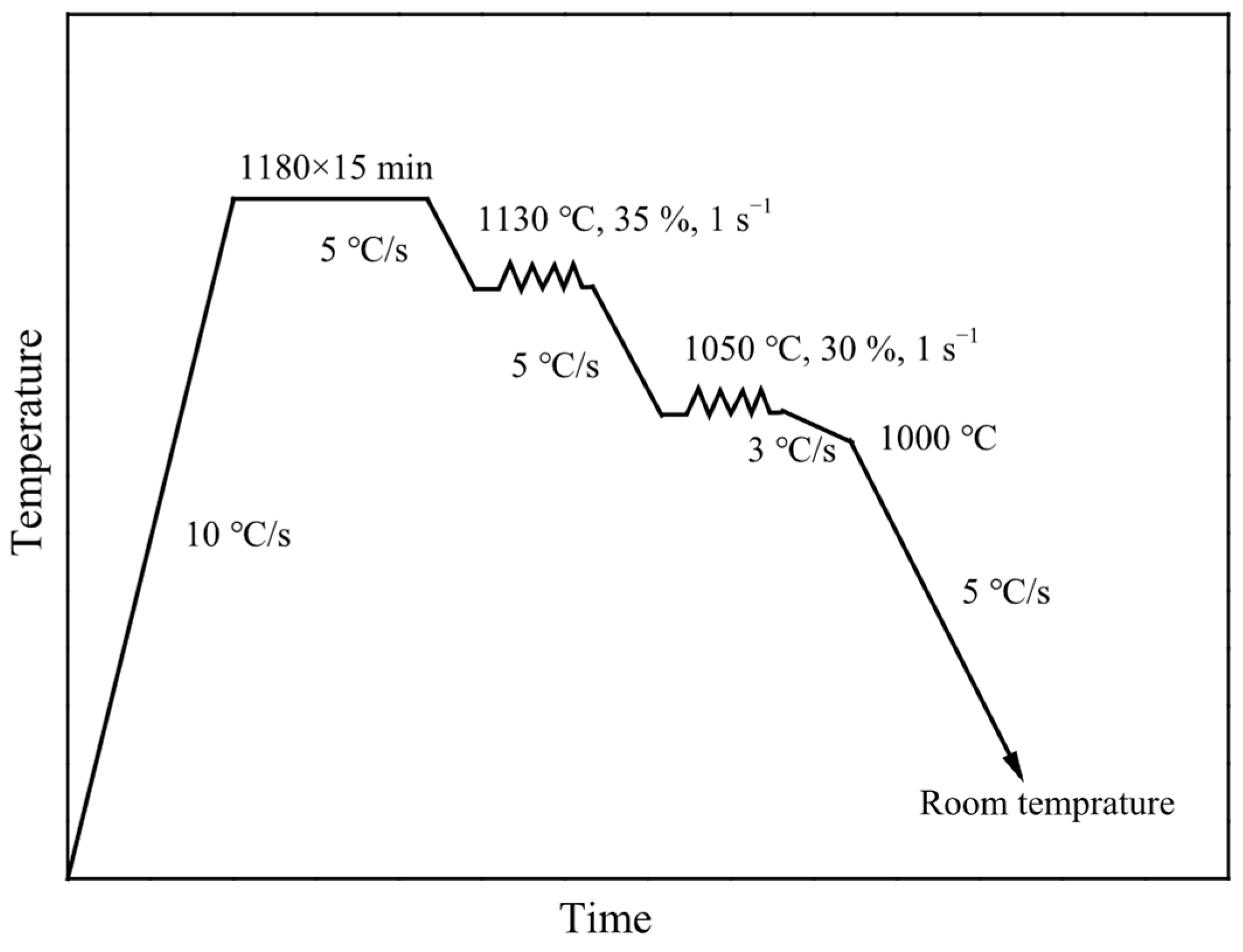
Figure 1. Schematic illustration of hot processing simulation schedule.
Metals 15 01025 g001
Figure 2. Schematic of sampling: (a) tensile sample sampling location and (b) cross-section of simulated sample (unit: mm).
Metals 15 01025 g002
Figure 3. Typical tensile stress–strain curves for different Mo content steels.
Metals 15 01025 g003
Figure 4. Typical impact load–deflection curves for different Mo contents.
Metals 15 01025 g004
Figure 5. Optical micrographs for different Mo content steels: 0Mo (a), 0.3Mo (b), 0.5Mo (c), and 1.0Mo (d).
Metals 15 01025 g005
Figure 6. SEM micrographs and the EDS analysis results in the rectangle of 0Mo (a,b) and 0.3Mo (c,d) samples.
Metals 15 01025 g006
Figure 7. EBSD inverse pole figures for different Mo content steels: 0Mo (a), 0.3Mo (b), 0.5Mo (c), and 1.0Mo (d).
Metals 15 01025 g007
Figure 8. Distribution of grain boundary misorientation for different Mo content steels.
Metals 15 01025 g008
Figure 9. TEM micrographs and twin morphologies of 0Mo (a,d) and 0.3Mo (b,e) samples. Low magnification and HRTEM image within rectangular area (c) and the electron diffraction pattern of the twin (f), dislocation morphologies (g), dislocations accumulated at the twin boundaries (h), and austenite grain boundaries (i) in the 0.3Mo samples.
Metals 15 01025 g009
Figure 10. XRD spectra for different Mo content steels.
Metals 15 01025 g010
Figure 11. SEM micrographs of fracture surface for 0Mo (a), 0.3Mo (d), and 1.0Mo (g) samples and further identification with high magnification of the fibrous areas (b,e,h) and radiating areas (c,f,i).
Metals 15 01025 g011
Figure 12. SEM micrographs of secondary cracks for 0Mo (a), 0.3Mo (b), and 1.0Mo (c) samples.
Metals 15 01025 g012
Figure 13. Yield strength as a function of grain size of samples with different Mo contents.
Metals 15 01025 g013
Figure 14. The trends of various strengthening contributions as a function of the Mo content.
Metals 15 01025 g014
Figure 15. The EBSD results of a typical intergranular fracture and transgranular fracture in the 0Mo and 0.3Mo samples: inverse pole figure (a,d), band contrast maps (b,e), and kernel average misorientation maps (c,f).
Metals 15 01025 g015
Table 1. Chemical compositions of four test steels (wt.%).
SteelCSiMnMoFe
0Mo1.080.3313.30.02Balance
0.3Mo1.080.3313.30.30Balance
0.5Mo1.110.3813.20.48Balance
1.0Mo1.090.3513.31.01Balance
Table 2. Summary of the mechanical results.
SteelYS (MPa)TS (MPa)TE (%)WiWpWt (J)
0Mo344 ± 7946 ± 1062 ± 468 ± 770 ± 5138 ± 12
0.3Mo373 ± 71013 ± 1160 ± 3105 ± 10122 ± 10227 ± 20
0.5Mo389 ± 81016 ± 1156 ± 3102 ± 9113 ± 11215 ± 20
1.0Mo415 ± 81023 ± 1348 ± 378 ± 788 ± 6166 ± 13
YS = yield strength; TS = tensile strength; TE = total elongation; Wi = crack initiation energy; Wp = crack propagation energy; Wt = total impact energy.
Table 3. Summary of the grain sizes, boundaries fraction, and dislocation densities.
SteelMean Diameter (μm)fAB (%)fTB (%)Dislocation Density (×1014 m−2)
0Mo7558.0539.757.07
0.3Mo4359.0736.647.59
0.5Mo3361.7134.887.86
1.0Mo2571.5123.668.61
Table 4. Typical misorientation of the austenite and twin boundaries for different Mo content steels.
SteelAustenite BoundariesTwin Boundaries
0Mo29.56° <-1-2-4>59.11° <-1-1-1>
34.58° <0-1-4>59.68° <-1-1-1>
45.34° <-1-2-4>59.45° <-1-1-1>
33.87° <-2-3-4>59.10° <-1-1-1>
0.3Mo35.05° <0-3-4>59.38° <-1-1-1>
39.16° <-1-4-4>59.79° <-1-1-1>
27.03° <-1-1-4>58.93° <-1-1-1>
36.01° <-2-3-4>59.28° <-1-1-1>
0.5Mo31.56° <-1-1-3>59.65° <-1-1-1>
38.97° <-1-1-2>59.83° <-1-1-1>
23.83° <-1-1-4>59.29° <-1-1-1>
38.21° <-1-4-4>59.98° <-1-1-1>
1.0Mo26.47° <-1-3-4>59.85° <-1-1-1>
52.38° <-1-2-4>59.49° <-1-1-1>
35.00° <-1-3-4>59.99° <-1-1-1>
32.01° <-1-1-3>59.45° <-1-1-1>
Table 5. Summary of individual strengthening contributions.
SteelYS (MPa)σ0 (MPa)σb (MPa)σd (MPa)(σs + σp) (MPa)
0Mo344247619153
0.3Mo3732410019851
0.5Mo3892411420150
1.0Mo4152413121149
Disclaimer/Publisher’s Note: The statements, opinions and data contained in all publications are solely those of the individual author(s) and contributor(s) and not of MDPI and/or the editor(s). MDPI and/or the editor(s) disclaim responsibility for any injury to people or property resulting from any ideas, methods, instructions or products referred to in the content.