Article

Multi-Scale Mechanical Anisotropy and Heat Treatment Effects in Additively Manufactured AlSi10Mg

by
Aikaterini Argyrou
1,
Leonidas Gargalis
2,
Leonidas Karavias
2,
Evangelia K. Karaxi
2 and
Elias P. Koumoulos
1,*
1
IRES—Innovation in Research & Engineering Solutions, Silversquare Europe, Square de Meeûs 35, 1000 Brussels, Belgium
2
Conify, Panteli Nikolaidi 23A, Ag. Ioannis Rentis, 182 33 Attiki, Greece
*
Author to whom correspondence should be addressed.
Metals 2025, 15(8), 890; https://doi.org/10.3390/met15080890
Submission received: 30 June 2025 / Revised: 1 August 2025 / Accepted: 5 August 2025 / Published: 8 August 2025
(This article belongs to the Special Issue Welding and Additive Manufacturing of Metals)

Abstract

This study investigates the combined effects of build planes and heat treatments on the micro- and nanoscale mechanical properties of additively manufactured AlSi10Mg alloy. The hardness and elastic modulus were examined across two principal planes, XY and XZ, under three conditions: as-built (AB), after solution annealing followed by water quenching (SA), and artificially aged after solution annealing (SA&AA). The results reveal that hardness is significantly affected by heat treatment, decreasing after SA and partially recovering upon subsequent artificial aging (SA&AA), while remaining largely unaffected by build planes, with average values differing by less than 2%. In contrast, the elastic modulus demonstrates a clear anisotropy, correlated with the microstructural changes from both additive manufacturing and thermal post-processing. The XY plane initially shows a modulus up to 29% higher than the XZ plane. However, after aging, the values of both planes converge to similar levels. While average values suggest general trends, localized measurements reveal notable spatial heterogeneity in both the hardness and elastic modulus—particularly after thermal treatments—arising from microstructural evolutions. These findings highlight the complex interplay between orientation and thermal history, underscoring that the mechanical performance of AlSi10Mg is governed by the synergistic effects that influence anisotropy and local mechanical behavior.

1. Introduction

Additive manufacturing (AM), also known as 3D printing, is a rapidly growing technology for producing metallic components with complex geometries and minimal material waste [1,2,3]. Its layer-by-layer fabrication approach enables design flexibility and rapid prototyping, making it particularly valuable in aerospace, automotive, and medical engineering [4,5,6]. Among the various metal AM methods, laser powder bed fusion (LPBF) has emerged due to its ability to produce near-net shape components with high precision and improved surface finish [7]. This process involves the selective melting of metal powder in a track-by-track and layer-by-layer fashion using a high-power laser in a controlled atmosphere, resulting in rapid solidification and refined microstructures that differ significantly from their cast counterparts [8].
Within the wide range of metallic systems compatible with AM, aluminum–silicon (Al-Si) alloys have gained considerable attention for their low weight and good mechanical response [9,10,11,12]. Among them, AlSi10Mg stands out for its low density and good corrosion resistance, making it suitable for high-performance applications [13,14]. Although originally developed for casting applications, AlSi10Mg adapts well to the thermal dynamics of LPBF, due to its eutectic composition and quick solidification rate, minimizing the risk of cracking during processing [15,16]. The rapid cooling rates—on the order of 106 K/s—resulting from the LPBF process induce ultrafine cellular microstructures that are distinctly different from the coarser dendritic microstructures typically seen in cast alloys [17,18,19]. However, these refined structures introduce challenges, including residual stresses and significant microstructural anisotropy caused by thermal gradients and directional solidification [20,21]. These features affect not only the bulk mechanical properties, but also contribute to local variations in hardness, strength, and deformation that are not captured through conventional macro-scale testing methods, underscoring the need for nanoscale techniques [22,23]. Indeed, recent studies on LPBF-manufactured metals have demonstrated the effectiveness of nanoindentation in characterizing local mechanical variations related to microstructural features [24].
To address these issues, post-processing heat treatments are commonly applied. The typical heat treatment of AlSi10Mg alloys involves solution annealing followed by water quenching and artificial aging (T6). Numerous studies have focused on the effects of these treatments, highlighting their role in modifying microstructural features and altering mechanical properties. For instance, Li et al. reported a decrease in tensile strength, but a substantial increase in fracture strain upon heat treatment, attributed to the precipitation and growth of Si particles [25]. Zhang et al. showed that the as-built continuous Si network breaks down into discrete particles after heat treatment, resulting in reduced fatigue performance [26]. Additionally, Clement et al. studied a T6-like treatment on selective laser-melted AlSi10Mg alloy and noted that while the process homogenized the microstructure, it also led to the formation of Fe-rich precipitates, causing precipitation hardening and increased hardness values [27].
Despite the improvements introduced by heat treatments, the anisotropy characteristic of the LPBF process remains a critical factor influencing mechanical performance. Due to the directional nature of layer-by-layer fabrication, the properties of AlSi10Mg are highly dependent on build orientation. Research has demonstrated that samples built in the XY plane typically display higher tensile strength and hardness compared to those built in the XZ plane. This behavior is assigned to variations in microstructural features, such as melt pool boundaries and silicon cell spacing, which influence mechanical properties like yield strength and ductility [28]. Moreover, orientation influences the formation of defects like pores and lack-of-fusion regions, which are more likely to align along the build direction, contributing to reduced mechanical performance [29].
While the effects of heat treatment and build orientation have been documented, their combined impact, particularly at the nanoscale, remains largely unexplored. This is important considering that LPBF introduces distinct microstructural features such as elongated melt pools, grain growth directionality, and layer-by-layer heterogeneity, all of which influence the mechanical properties on a small scale [30,31,32]. For example, Maeshima et al. investigated the aging behavior of AlSi10Mg alloys produced via LPBF, highlighting the formation of nanoscale clusters within α-Al cells during aging, which contributed to increased hardness [33]. However, the research did not address the role of build orientation in these changes. Similarly, Brandl et al. examined the tensile behavior and microstructure of LPBF-processed AlSi10Mg, noting that heat treatment homogenized the microstructure and transformed Si particles into a globular form, reducing differences across build orientations [34]. Despite these findings, their analysis primarily focused on macroscopic properties like fatigue resistance and tensile strength, leaving the nanoscale implications of build direction unexplored.
Most existing studies investigate heat treatment and build planes separately, overlooking potential interactions that could influence mechanical anisotropy more profoundly. Moreover, emphasis has been placed on enhancing macroscopic properties, while little attention is given to how post-processing affects local mechanical behavior. This study aims to address these gaps by systematically investigating the build plane-dependent mechanical properties of LPBF-manufactured AlSi10Mg and examining how these properties evolve under various post-process heat treatment regimes. By combining nanoindentation with detailed elemental characterization, we investigate the anisotropic response in both AB and heat-treated samples across the XY and XZ build planes. Specifically, we focus on nanohardness and the elastic modulus to uncover the underlying mechanisms governing local mechanical variation. Additionally, to capture these effects at different scales, Vickers microhardness testing was performed to provide a microscale perspective. Through these approaches, we aim to deepen the fundamental understanding of additively manufactured AlSi10Mg but also provide practical insights into optimizing its mechanical performance.

2. Materials and Methods

Commercially available gas-atomized aluminum-grade AlSi10Mg metal powder (m4p™ AlSi10Mg, m4p material solutions GmbH, Feistritz im Rosental, Austria) was used as LPBF feedstock. The chemical composition is presented in Table 1. The average powder particle size was 27 μm, with 90% of particles (D90) below 58 μm. The morphology of the powder, shown in Figure 1, was examined using a Scanning Electron Microscope (SEM) (Phenom ProX, Thermo Fisher Scientific Inc., Waltham, MA, USA) operating at an acceleration voltage of 15 kV.
Additive manufacturing was carried out using an LPBF machine (INTECH, SF1 iFusion150, Intech Additive Solutions Ltd., Bangalore, India) equipped with a 500-watt ytterbium-fiber laser and a spot size of 80 ± 5 µm. Fabrication was performed on a circular aluminum build plate with a diameter of 150 mm, which was maintained at 150 °C throughout the process. The build chamber was purged with high-purity argon gas (Grade 5.0) to ensure that oxygen levels remained below 0.5 ppm. The optimum process parameters for the specific aluminum metal powder were defined experimentally. Initial experimental trials were conducted using AlSi10Mg alloy powder, with variations in laser power, scan speed, and hatch distance to establish a narrow range of suitable process parameters. To determine the optimal set of process parameters, the volumetric energy density (VED) was calculated using Equation (1):
E = P/(v × h × t) (J/mm3)
where P is the laser power in W, v is the laser scan speed in mm/s, h is the hatch distance between adjacent laser scan tracks in mm, and t is the layer thickness of the powder in mm. The laser power was set at 400 W, scanning speed at 1200 mm/s, hatch distance at 0.16 mm, and the layer thickness was kept stable at 40 μm, resulting in a volumetric energy density of 52 J/mm3. This set of parameters was the optimum, resulting in >99.9% relative densities, and three cubes of 10 × 10 × 10 mm (L × W × H) were fabricated. Two of the cubes underwent heat treatment, while the third remained in the as-built (AB) condition. Both heat-treated samples were solution-annealed at 450 °C for 2 h followed by water quenching (SA). One of these samples was further subjected to artificial aging at 165 °C for 6 h, followed by air cooling (SA&AA). A temperature ramp rate of 10 °C/min was used in both cases. Heat treatments were conducted in a chamber furnace (BOX-AS20-1600, THERMANSYS, Thessaloniki, Greece) capable of reaching temperatures of up to 1600 °C.
Following production and subsequent heat treatments, the cubes were subjected to a standard metallographic preparation procedure. The cubes were sectioned using a precision micro-cutting machine (Mecatome T210, PRESI, Paris, France), followed by mounting, grinding, and polishing with an automated system (Tegramin-20, STRUERS, Birmensdorf, Switzerland). Cross-sections were prepared in both the XY (transverse to the build direction) and XZ (parallel to the build direction) planes for each cube (Figure 2). The samples were ground to a 2000-grit finish, polished using 3 μm and 1 μm diamond suspensions, and finalized with 0.2 μm fumed silica suspension. To reveal the microstructure, the polished surfaces were etched with Kroll’s reagent (2 mL HF, 6 mL HNO3, and 92 mL distilled water) for 10–15 s. Microstructural analysis was performed using the Phenom ProX SEM equipped with an energy dispersive spectroscopy (EDS) detector for phase identification.
Vickers microhardness measurements were carried out on both the XY and XZ planes of the AB, SA, and SA&AA samples. Testing was conducted using an INNOVATEST FALCON 400G2 Vickers microhardness tester (INNOVATEST Europe BV, AA Maastricht, The Netherlands) under dry conditions at room temperature. A load of 0.5 kgf was applied for 10 s, in accordance with ASTM E384-22 [35]. For each condition, a 3 × 3 indent array was performed, ensuring spacing exceeding 2.5 times the average diagonal length of each indent (ASTM E384-22 [35]).
To provide complementary insight into the local mechanical behavior of AlSi10Mg, nanoindentation tests were performed on AB, SA, and SA&AA samples. Measurements were conducted on both the XY and XZ planes using a nanoindenter (Hysitron TS 77 Select, Bruker, Minneapolis, MN, USA), equipped with a high-load Berkovich diamond tip (half angle: 65.27°, included angle: 142.3°; C0: 24.5; Young’s modulus: 1140 GPa; and Poisson’s ratio: 0.07). Indentation tests followed a standard load function consisting of a 40 s loading segment, a 3 s hold at peak load, and a 40 s unloading segment. A 10 × 10 array of indents was performed with a spacing of 20 µm between each individual point to minimize interaction effects. All measurements were carried out under ambient conditions and were used to evaluate the local hardness and elastic modulus of the material. The target depth used during indentation was 1000 nm.
SEM/EDS analysis at 15 and 20 kV was employed to demonstrate the nanoindentation regions and analyze their elemental composition, supporting the correlation between microstructural evolution and the localized mechanical response.

3. Results

3.1. Microstructure

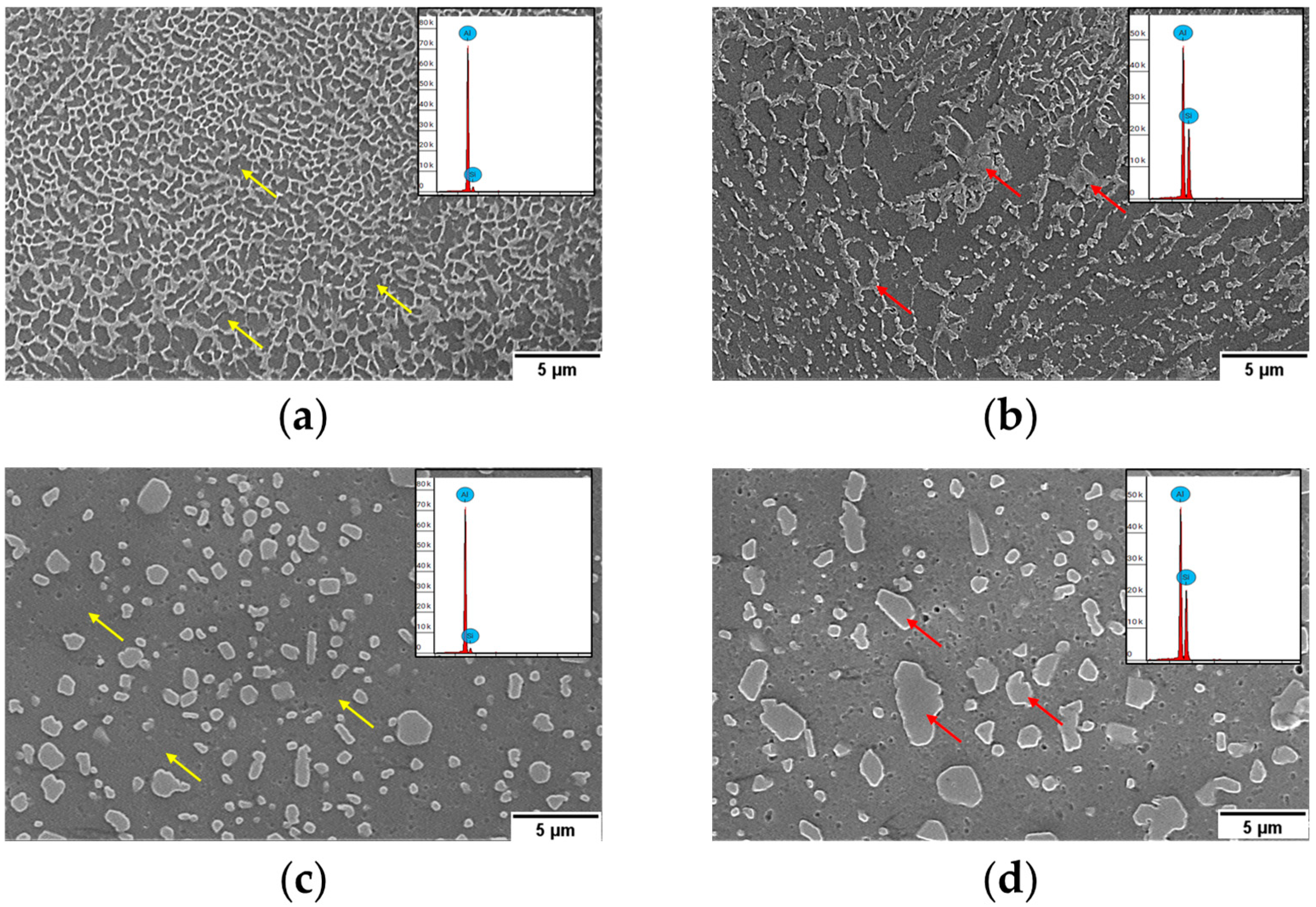
The microstructure of AlSi10Mg in the AB condition is illustrated in Figure 3a,b, while the heat-treated states are presented in Figure 3c,d. In the AB condition, the LPBF-manufactured AlSi10Mg alloy primarily consisted of a supersaturated α-Al matrix with a finely dispersed Si eutectic network. EDS spot elemental analysis confirmed the presence of the Si-rich eutectic network, showing an increased silicon concentration of up to 12.3 wt.% compared to approximately 6.5 wt.% in the surrounding α-Al matrix. In the XY plane, a continuous cellular eutectic Si network surrounded the α-Al matrix. In contrast, the XZ plane revealed a columnar, dendritic-like arrangement of Si around the Al matrix, reflecting directional solidification along the build direction. This grain anisotropy is attributed to thermal gradients and the layer-by-layer deposition characteristic of the LPBF process. Due to the rapid solidification during LPBF, a significant fraction of Si remains in a metastable state within the Al matrix (supersaturation) [36]. The remaining Si is not uniformly dispersed in the α-Al matrix, but instead it precipitates as hard Si-rich eutectic networks due to non-equilibrium solidification and rapid cooling [37].
Upon SA and SA&AA, the microstructure undergoes significant changes. The microstructures in the SA and SA&AA conditions appear similar for both XY and XZ planes. Specifically, in both heat-treated conditions, the microstructure revealed both coarse and fine globular Si particles dispersed within the α-Al matrix. EDS analysis validated these observations, with localized Si concentrations in the particles reaching up to 46.0 wt.%, while the α-Al matrix contained approximately 8.8 wt.% Si. The distinct morphological changes confirm the transformation of the Si eutectic network into globular and spheroidized Si particles through heat treatments.

3.2. Micro- and Nanomechanical Properties

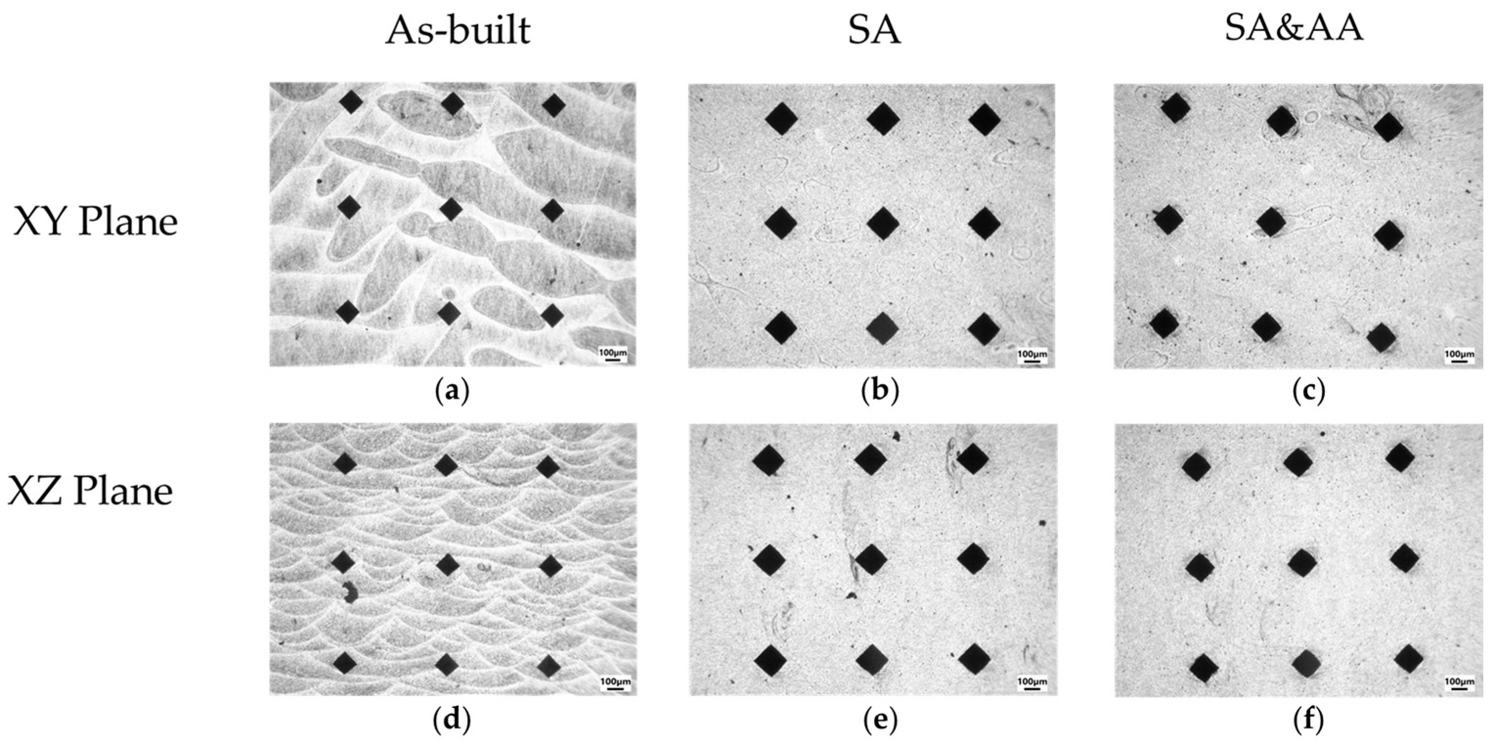
The microhardness indent arrays are presented in Figure 4 for all three conditions (AB, SA, and SA&AA) and both the XY and XZ planes. As shown in the microhardness impressions, the smaller indent sizes observed in the AB condition indicate higher hardness compared to the heat-treated states. Among the heat-treated samples, the SA&AA condition exhibited slightly smaller indents than the SA condition, suggesting relatively higher hardness. The average Vickers microhardness (HV0.5) values for each condition and plane are summarized in Table 2. The highest hardness was recorded in the AB condition, with values of 127.7 HV0.5 and 125.0 HV0.5 for the XY and XZ planes, respectively. The SA&AA condition featured hardness values of 83.3 HV0.5 (XY) and 83.7 HV0.5 (XZ), while the lowest hardness was measured in the SA condition, with values of 68.1 HV0.5 and 69.2 HV0.5 for the XY and XZ planes, respectively. No significant difference in average microhardness was observed between the XY and XZ planes across all conditions, indicating that the AlSi10Mg alloy produced via LPBF exhibits mechanical isotropy at the microscale.
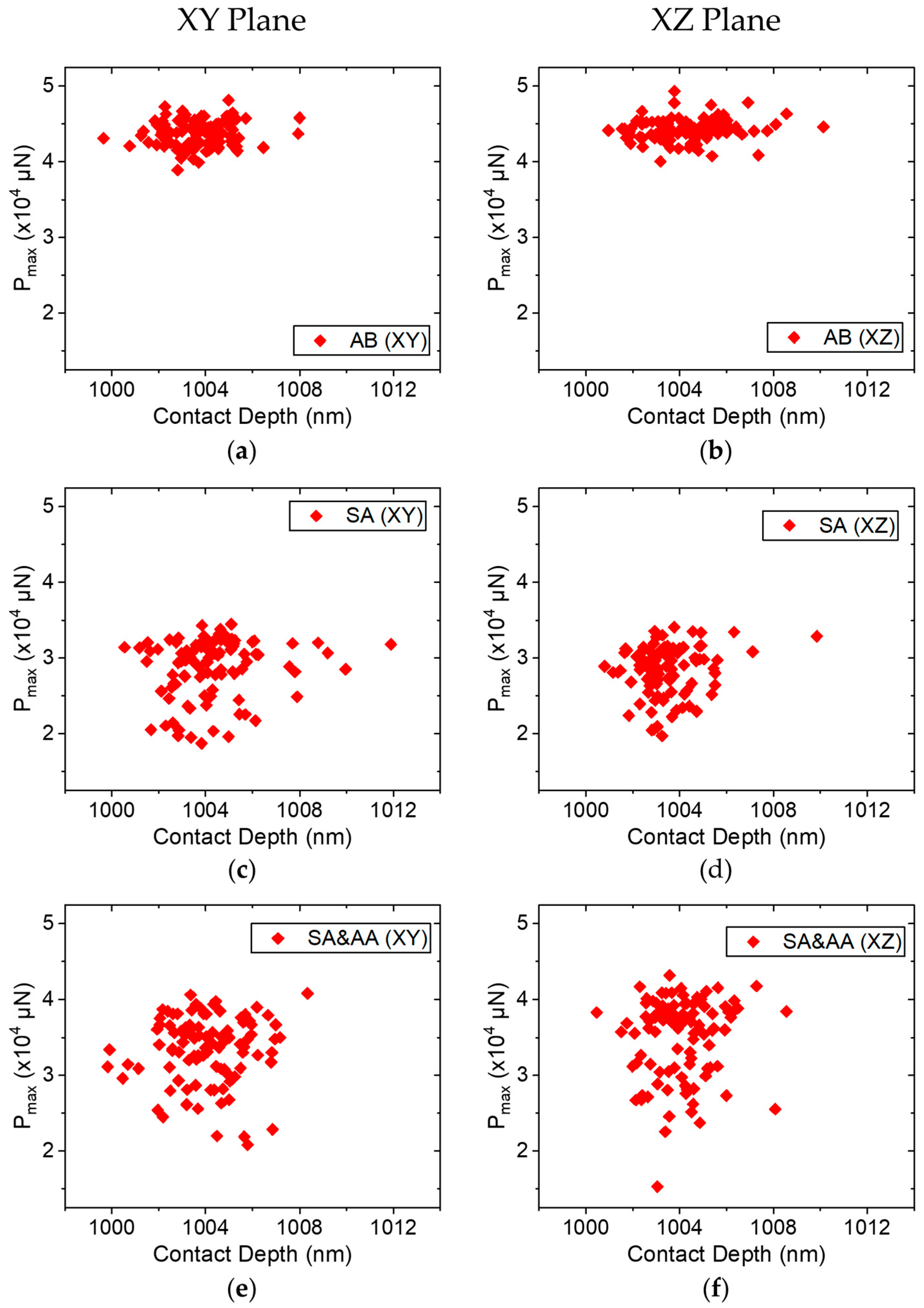
While Vickers microhardness reflects the bulk mechanical response, nanoindentation provides higher-resolution insights into localized variations influenced by microstructural features. Accordingly, nanoindentation experiments were performed on AlSi10Mg specimens sectioned along the XY and XZ planes under the three processing conditions: AB, SA, and SA&AA. Figure 5 presents the maximum indentation load (Pmax) as a function of contact depth for each condition. It can be observed that the AB condition exhibited the highest peak loads at the given indentation depth among the three states, indicating greater resistance to plastic deformation.
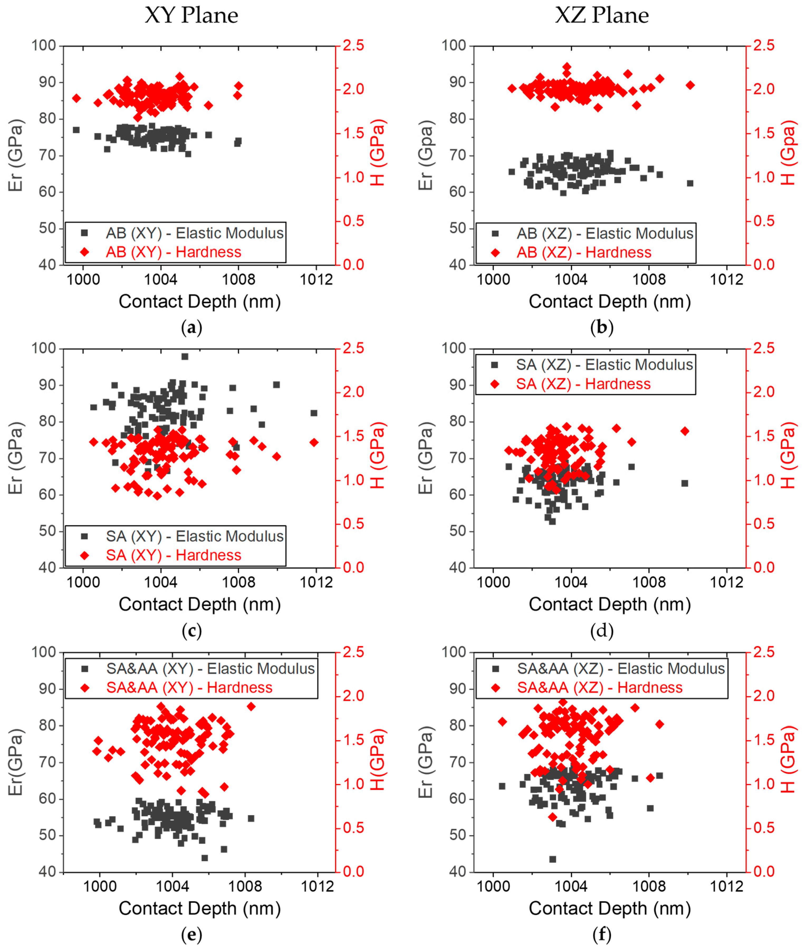
The quantitative evolution of mechanical properties is displayed in Figure 6, which shows scatter plots of nanohardness (H) and the reduced elastic modulus across (Er) all conditions and both planes. The average values are summarized in Table 3, highlighting the clear dependency of mechanical properties on both surface orientation and post-treatment conditions. These findings confirm the anisotropic behavior related to the manufactured process and the strong microstructural sensitivity to thermal treatments. Among the three different states, the AB condition demonstrates the highest strength, with a mean hardness value of 1.94 ± 0.09 GPa and 2.01 ± 0.08 GPa in the XY and XZ plane, respectively. This is evident in Figure 6a,b, where a dense clustering at higher values for the AB condition is observed. Notably, the elastic modulus in the XY plane is higher compared to that of the XZ plane, with mean values of 75.4 ± 1.6 GPa and 65.9 ± 2.5 GPa, respectively.
Following SA, substantial changes in mechanical properties were observed across both planes (Figure 6c,d). The average nanohardness values decreased compared to the AB state down to 1.42 ± 0.22 GPa in the XY plane and 1.35 ± 0.16 GPa in the XZ plane, accompanied by modulus values of 83.2 ± 6.0 GPa and 64.6 ± 3.3 GPa, respectively.
SA&AA resulted in a partial recovery of hardness in both planes, with the XY plane reaching 1.55 ± 0.21 GPa and XZ plane achieving 1.61 ± 0.24 GPa. Meanwhile, the elastic modulus decreases significantly to 55.2 ± 2.7 GPa in the XY plane and stabilizes at 64.4± 3.8 GPa in the XZ plane (Figure 6e,f).
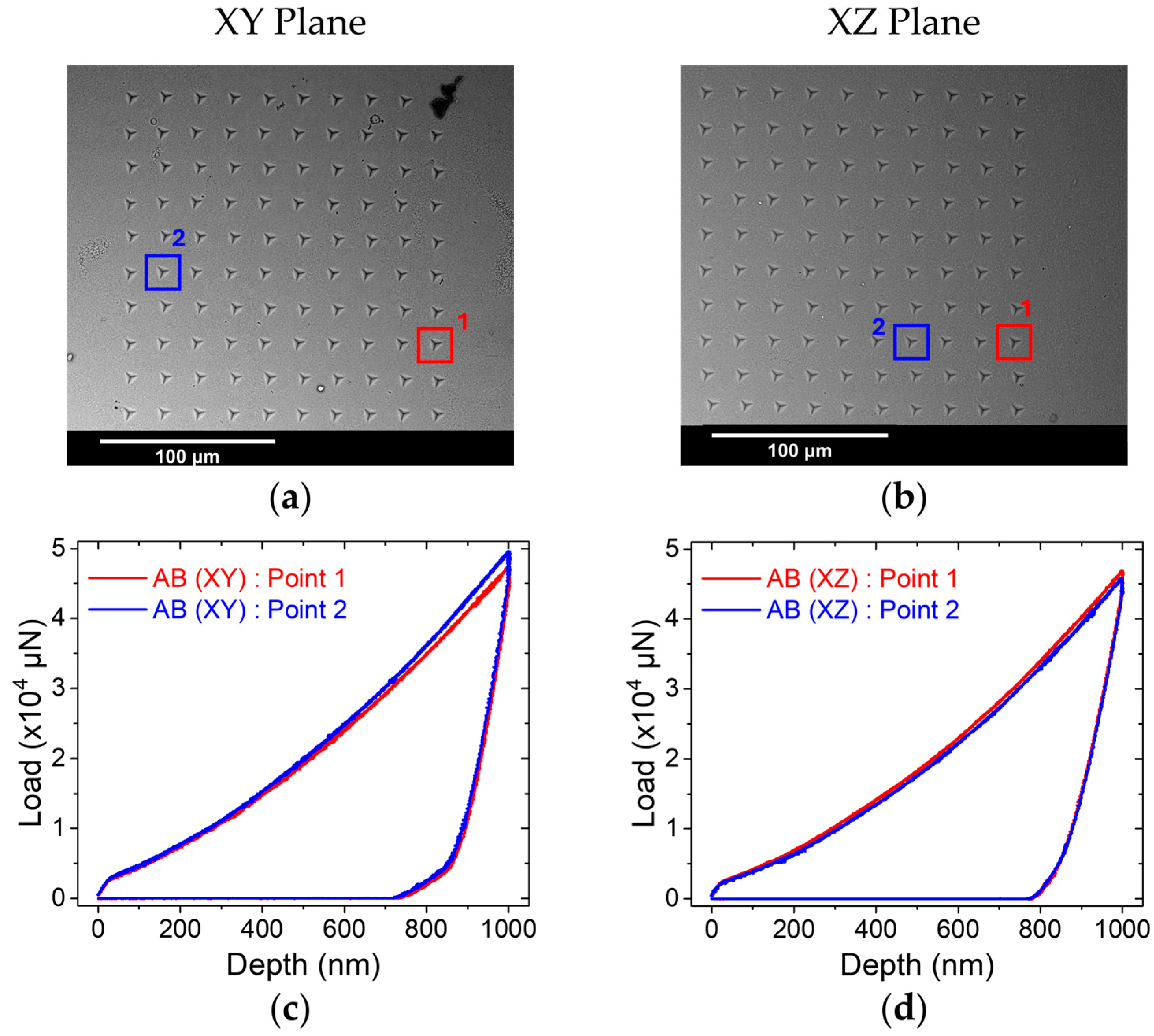
To further explore localized mechanical behavior, representative load–displacement curves alongside the corresponding SEM images for the AB condition in both planes are shown in Figure 7. Interestingly, both orientations displayed similar curve characteristics within the same specimen and between the two planes, suggesting a homogenous microstructure.
To extend this comparison across the post-treatment conditions, Figure 8 presents the representative nanoindentation curves selected from 100 performed indents per sample in the XY plane. For clarity, only one characteristic curve for each condition is shown, selected based on EDS analysis to indicate Si- and Al-rich regions. In the AB condition (Figure 8a), the elemental distribution of both Al and Si appears relatively uniform (Figure 8d,g,j), thus, both indents exhibited similar curve characteristics (Figure 8m). In contrast, after post-processing, Si-rich sites (Figure 8b,c, blue squares)—identified via EDS mapping (Figure 8e,f,h,i)—exhibited steeper initial loading slopes, indicating higher stiffness compared to the Al-rich sites (Figure 8b,c, red squares), which demonstrated smoother loading characteristics and higher deflection under the specific load (Figure 8n,o). This behavior aligns with the intrinsic hardness of silicon, which is significantly greater than that of aluminum [38].
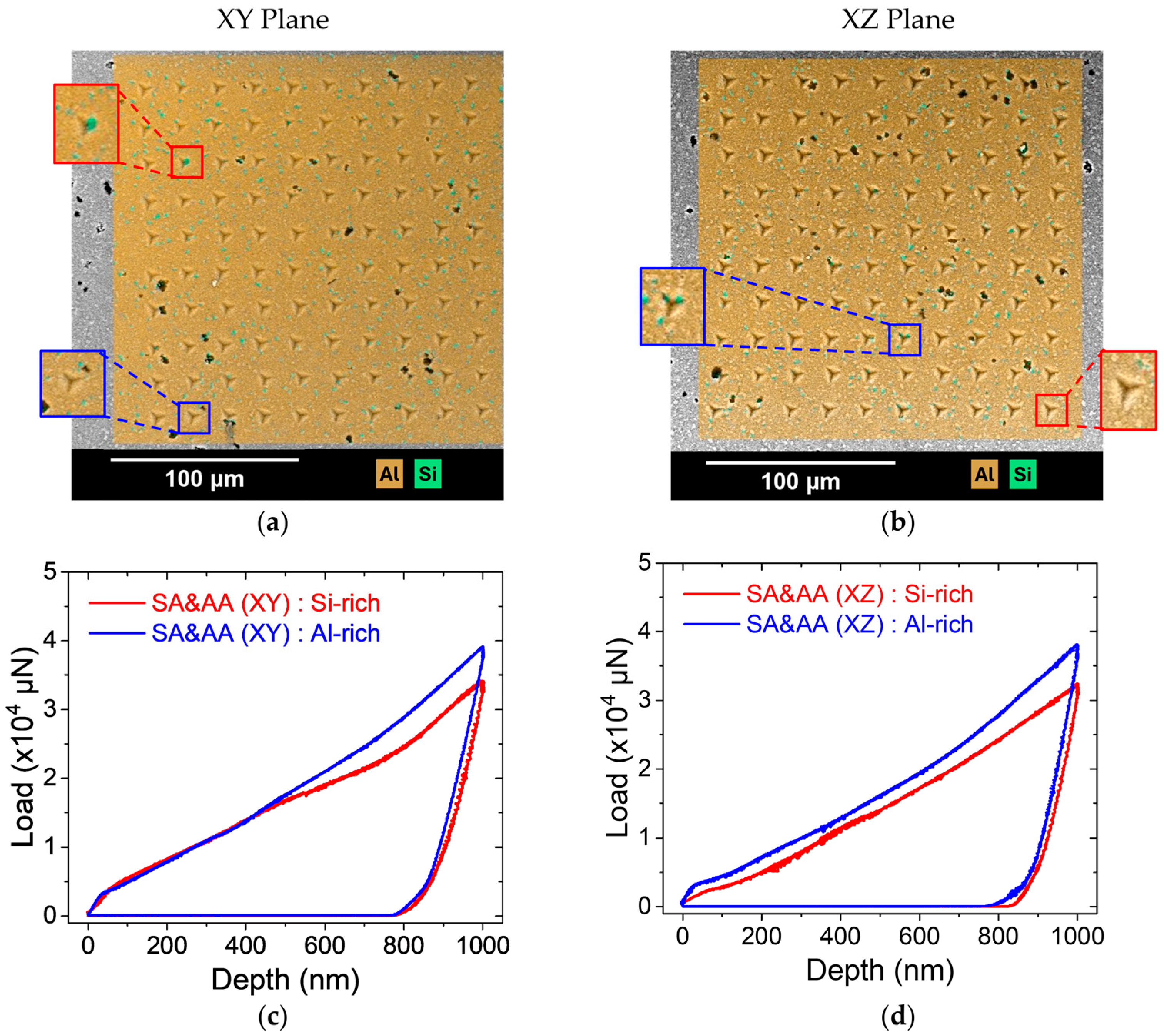
To further explore this mechanical heterogeneity, Figure 9 presents additional SEM-EDS overlays of the nanoindentation sites for SA&AA samples in both the XY and XZ planes. Similarly to Figure 8, two indentation sites were selected in each plane—one in an Al-rich region (Figure 9a,b, red square) and one in a Si-rich region (Figure 9a,b, blue square). The corresponding load–displacement curves (Figure 9c,d) confirm earlier observations by showing that Si-rich sites exhibit irregular, shallower responses, whereas Al-rich areas show smoother curves with greater penetration depths, suggesting higher plasticity.
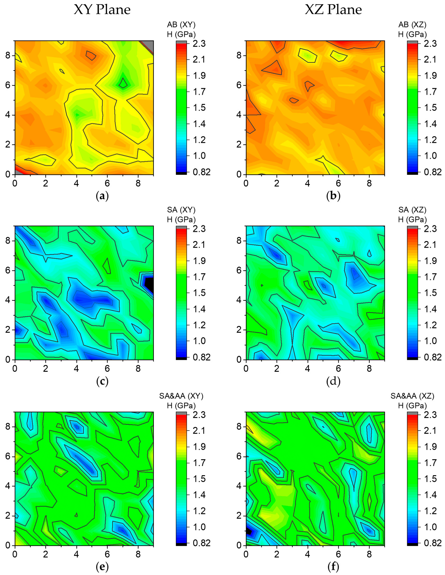
Figure 10 displays the spatial contour plots of hardness across the test surfaces. These maps further emphasize the uniformity, with slightly elevated regions in the AB state (Figure 10a,b). In contrast, the SA condition reveals notable regions of reduced hardness, reflecting the underlying microstructural coarsening (Figure 10c,d). The SA&AA samples reintroduce some homogeneity, with visible strengthened regions, particularly in the XZ plane (Figure 10e,f).
Figure 11 depicts the corresponding modulus contour plots. The AB state features relatively homogeneous distributions in both orientations. However, upon SA, the elastic modulus increased noticeably in the XY plane, suggesting microstructural rearrangements. The SA&AA process, while partially restoring hardness, led to a more fragmented distribution of the elastic modulus in the XY plane, indicating evolving mechanical heterogeneity.

4. Discussion

The mechanical response of additively manufactured AlSi10Mg, as revealed through both microhardness and nanoindentation testing, displayed complex interdependencies between build direction planes and thermal post-processing. These relationships arise from anisotropic features and the distinct microstructural evolution induced by both the layer-by-layer deposition method and the applied thermal gradients associated with the LPBF manufacturing process. Variations in grain morphology, elemental distribution, precipitations, and residual stresses affect the mechanical properties, highlighting the critical role of processing conditions and post-heat treatments in material behavior [39,40].

4.1. Anisotropy-Dependent Mechanical Properties

Microhardness measurements revealed the minimal impact of build orientation on Vickers hardness values. Across all three processing conditions—namely AB, SA, and SA&AA—hardness values in the XY and XZ planes were comparable, with differences falling within the standard deviation (Table 2). This consistency suggests that the alloy exhibits a near-isotropic mechanical response in terms of hardness across build planes. While other mechanical properties such as tensile strength and elongation to failure have shown sensitivity to build orientation in previous studies, the present results indicate that hardness is less affected [41]. This discrepancy highlights the complexity of microstructural effects in additively manufactured materials, where local mechanical responses may not directly reflect the anisotropy observed in bulk properties.
This observation is particularly noteworthy considering the microstructural differences between the build planes in the AB condition. Grain orientation and the distribution of the Si eutectic network vary between the XY and XZ planes. For instance, previous electron backscatter diffraction (EBSD) studies have reported distinct grain morphologies between the XY and XZ planes of AlSi10Mg in the AB state, attributed to directional solidification [33,42]. Typically, elongated columnar grains form along the XZ build direction, whereas the scanning XY plane features predominantly equiaxed grains with a bimodal size distribution. Nonetheless, despite these structural distinctions, the average grain size and crystallographic orientation remain largely similar across both planes, leading to similar microhardness values [43,44] and supporting the consistent hardness observed in this study.
Following heat treatments, the uniformity in microhardness values between the XY and XZ planes persisted (Table 2). This observation aligns with prior studies indicating that common heat treatments reduce directional anisotropy in AlSi10Mg, leading to comparable Vickers microhardness values across build planes due to microstructural homogenization [45,46].
The nanohardness results further corroborated the microhardness findings, demonstrating that the average hardness values were statistically indistinguishable between the XY and XZ planes under all processing conditions (Table 3). This consistency across both measurement techniques suggests that resistance to plastic deformation is largely independent of the build direction under the examined conditions. This conclusion is further supported by Figure 10, which illustrates similar hardness characteristics in terms of uniformity and fragmentation patterns across the two planes within each processing state.
While the overall trend indicates isotropic mechanical behavior between the two planes, minor differences were still observed. Particularly in the AB condition, Pmax values were closely clustered across both XY and XZ planes, reflecting a uniform local response (Figure 5a,b). However, the XZ plane displayed slightly tighter distribution, which may be attributed to the alignment of columnar grains and cellular structures along the build direction. In contrast, the XY plane intersects multiple melt pool boundaries, which may introduce localized heterogeneity and higher variability in the mechanical response [47]. This effect is further demonstrated in the hardness–depth profiles (Figure 6a,b, red diamond), where both planes exhibited narrow distributions, but the XY plane showed a slightly greater variability. Despite this, nanoindentation curves within each plane were highly consistent, suggesting a generally uniform mechanical response across spatial locations (Figure 7).
In contrast to hardness, which is governed by plastic deformation, the behavior of stiffness—represented by the elastic modulus—is more complex due to its sensitivity in the surrounding phases [48]. In the AB condition, the XY plane showed higher average modulus values and greater local variability (Figure 6a,b, gray squares). This effect is further evident in elastic modulus contour plots that showed a more uniform spatial distribution in the XY plane along the indentation region compared to its XZ counterpart (Figure 11a,b).
This observed modulus anisotropy aligns with findings in other additively manufactured metals, where horizontally built specimens demonstrate higher elastic moduli than vertically built ones [49,50]. Such trends have been attributed to the combined influence of microstructural anisotropy and residual stress distributions associated with the additive manufacturing process. For example, tensile testing of AlSi10Mg revealed that vertically built specimens exhibit a lower Young’s modulus compared to horizontally built specimens [51].
After post-processing, site-specific mechanical contrast became more apparent (Figure 9). In both SA and SA&AA conditions, wider distributions for maximum load (Figure 5c,d), hardness (Figure 6c–e, red diamond), and the elastic modulus (Figure 6c–e, gray square) across the two planes were observed. These changes are attributed to the increased microstructural variability caused by the thermal coarsening and spheroidization of Si, which reduced the uniformity of the specimens. This behavior is well-documented in the literature, where the mismatch in mechanical properties between the Al matrix and the Si phase are reported [52].
Moreover, despite the broader scatter, modulus values between the XY and XZ planes in the SA&AA condition converged toward similar levels, indicating that the thermal treatments helped to reduce directional disparity. This localized behavior is further depicted in EDS maps (Figure 9a,b) and the corresponding load–displacement curves (Figure 9c,d). Here, the elemental maps distinctly differentiate Si-rich regions (green color) from Al-rich regions (yellow color). These compositional distributions correlate directly with the mechanical response measured through nanoindentation. Specifically, Si-rich regions consistently showed higher resistance to indentation (Figure 9c,d, blue curves), while Al-rich regions exhibited greater penetration under load (Figure 9c,d, red curves). These trends are in agreement with prior studies, where the nanoindentation of an Al-rich site yielded a hardness of 0.92 GPa compared to 2.28 GPa in a Si-enriched area [22]. Notably, a pop-in event was observed in the loading segment of Si-rich regions (Figure 9c,d, red curves), likely indicating the fracture of Si particles. On the other hand, across both planes, a smoother, continuous loading was observed in Al-rich regions, characteristic of homogeneous plastic deformation. These compositional effects remained consistent between the XY and XZ planes in the post-treatment conditions (Figure 9), reinforcing the idea that local heterogeneity plays a more critical role than build orientation in determining the nanoscale mechanical response.

4.2. Effect of Heat Treatment

The effect of heat treatment on the nanoscale mechanical properties of AlSi10Mg was thoroughly evaluated within each plane to isolate any potential role of microstructural orientation. In the AB condition, the alloy exhibited the highest nanohardness values, and a relatively high elastic modulus across both planes (Figure 6a,b). This performance is attributed to the rapid solidification typical of LPBF, where the rapid cooling results in the fine, homogenous distribution of alloying elements, contributing to the strengthening as well as the stabilization of the microstructure of AlSi10Mg [53]. This uniformity is further reflected in Figure 8m, where the load–displacement curves of two representative indents across the XY plane (Figure 6a) exhibit similar characteristics, indicating consistent mechanical responses across orientations. Additionally, EDS mapping (Figure 8d,g,j) demonstrated a relatively uniform elemental distribution of both Al and Si. The nanohardness results correlate well with Vickers microhardness measurements, further confirming the uniformly hardened structure in the AB state (Table 2 and 3). The observed mechanical properties in the AB AlSi10Mg arise from a combination of strengthening mechanisms, all influenced by the thermal conditions during the LPBF process [54]. One key factor is solid solution strengthening, caused by the atomic size difference between Si and Al in the FCC lattice. This disparity induces localized strain fields that limit dislocation movement, thereby improving both hardness and the elastic modulus [55]. Additionally, the rapid solidification process leads to the formation of a refined cellular microstructure with closely packed grain boundaries. These grain boundaries act as barriers to dislocation movement, enhancing the alloy’s resistance to plastic deformation through Hall–Petch strengthening [56]. Furthermore, thermal gradients during LPBF also increase the dislocation density within the microstructure. These dislocations are often trapped by the eutectic Si network, which enhances the material’s strength [57].
Following SA, a notable reduction in hardness was observed (Figure 6b,c, Table 3), reflecting significant changes in the microstructure. As shown in Figure 3, the fine Si eutectic network observed in the AB condition (Figure 3a) breaks down and transforms into coarser spheroidized and globular Si particles dispersed in the α-Al matrix (Figure 3c). EDS mapping further confirmed this transformation, revealing more clustered and isolated Si-rich regions compared to the uniform distribution in the AB state (Figure 8d,e,g,h,j,k). This microstructural change is typical after solutionizing, where high temperatures promote grain growth, the disintegration of the Si network structure, and the spheroidization of eutectic Si [19]. This coarser, globular Si morphology reduces the hardening effect originally featured in the fine Si network, thereby decreasing the overall hardness of the alloy. In addition, SA results in a reduction in residual stresses from LPBF processing, which can improve resistance to crack initiation and propagation [38]. Corresponding load–displacement curves in Figure 8n reveal the spatial variation in the mechanical response, with Si-rich regions exhibiting higher displacement resistance (Figure 8n, blue curve) than Al-rich areas (Figure 8n, red curve). Furthermore, hardness contour plots show a more irregular distribution, characterized by fragmented clusters post heat treatment (Figure 10a–d). Similar microstructural evolution and mechanical property degradation were reported by Shakil et al., who showed that while water quenching after solution treatment can trap solute atoms and vacancies in a supersaturated solid solution, it does not restore the fine cellular microstructure characteristic of LPBF. Instead, the coarsening of the microstructure occurs, which negatively impacts the alloy’s mechanical performance [19].
Additionally, prior studies on Al-Si-Mg alloys have shown that variations in quench rates significantly impact the size and distribution of precipitates [58]. Specifically, at lower quenching rates, the formation of coarse Mg2Si precipitates and precipitate-free zones within the microstructure has been shown to reduce strength and ductility, as they introduce brittle phases and weaken the alloy matrix. This heterogeneous phase distribution likely contributes to the increased scatter observed in the elastic modulus (Figure 6a–d, gray squares).
Upon SA&AA, mechanical performance showed a partial recovery towards the AB state in terms of both micro- and nanohardness (Table 2 and Table 3). SEM imaging revealed slightly larger Si particles in the SA&AA microstructure compared to the SA condition (Figure 3c,d), suggesting continued coarsening of the Si phase during artificial aging. Furthermore, while load–displacement curves showed comparable characteristics between the two conditions for the selected regions, the responses in SA&AA display higher peak loads, showing a modest enhancement in localized mechanical resistance after aging (Figure 8n,o). Additionally, EDS maps indicate no significant elemental refinement between the post-treatment states; however, a more diffuse distribution of Si precipitates may be inferred (Figure 8b,c,e,f,h,i).
Despite the morphological changes observed after SA&AA, aging may promote the formation of a finer distribution of Mg2Si phases, which are evidenced to contribute to the strengthening of AlSi10Mg alloys [59]. Nevertheless, the characteristic cellular microstructure observed in the AB condition is absent after the SA&AA heat treatment, indicating that the heat treatment primarily affects the secondary phases rather than restoring the AB microstructure (Figure 3a,d).
Unlike the solution hardening observed in the SA condition, the mechanical behavior in SA&AA is primarily governed by precipitation age hardening mechanisms. This process is dominated by Orowan strengthening, where the finely distributed Mg2Si precipitates act as a barrier to dislocation movement [60]. These nanoscale precipitates, observable only through transmission electron microscopy (TEM), force dislocations to bow around them, increasing resistance to plastic deformation [59,61]. This behavior is in accordance with the observed slight hardness improvement after SA&AA (Table 3). In terms of stiffness, Figure 6b,d,f reveal that the elastic modulus retained its heterogeneity across the XZ orientation, regardless of post-processing treatments. This stability can be further observed in elastic modulus contour plots (Figure 11b,d,f) and can be possibly attributed to the intrinsic microstructural characteristics induced during the LPBF process. Specifically, unlike the equiaxed grains typically formed in the horizontal orientation, the XZ plane is known to promote the formation of columnar grains [62,63]. These columnar grains possibly maintain to some extent their orientation and bonding characteristics even after heat treatments, resulting in a consistent elastic modulus across different thermal conditions. This crystallographic stability is further supported by Liu et al., who demonstrated through EBSD analysis that the elongated α-Al grains oriented along the Z-axis remained largely unchanged after heat treatments [64].
Conversely, in the XY plane, the distribution of the elastic modulus became narrower upon subsequent aging (Figure 6e). This may be linked to the coarsening of Mg-Si precipitates and the degradation of Si-rich cell boundaries, which act as stiffening features in the microstructure. While precipitation hardening during aging improves strength through Orowan mechanisms, the breakdown of Si-rich cell boundaries and the loss of coherency of precipitated Mg-Si nanophases reduce internal stiffness, resulting in a softer elastic response despite improved hardness [65].

4.3. Interaction Between Anisotropy and Heat Treatment

The mechanical properties of additively manufactured AlSi10Mg are not solely dictated by the build direction plane or thermal post-processing, but rather emerge from the interplay between these two factors. While each independently affects hardness and stiffness, their interaction creates complex effects that are governed by underlying structural reorganizations and localized compositional shifts.
Across both the XY and XZ planes, the alloy exhibited near-isotropic hardness profiles within each processing condition; however, the role of anisotropy and heat treatment becomes more evident when considering stiffness variations, local heterogeneity, and phase morphology. In the AB condition, differences in the mechanical response between the XY and XZ planes are primarily attributed to the solidification patterns induced during the LPBF process. In the XY plane, the laser scanning path promoted the formation of a more continuous Si network, contributing to its higher elastic modulus. In contrast, the XZ plane, which is oriented perpendicular to the melt pool layers, exhibited columnar grains that disrupt the Si structure, resulting in comparatively lower stiffness. This disparity establishes a clear baseline for anisotropy, where build orientation defines the elastic behavior, while hardness remains largely unaffected. These observations suggest that, under the AB conditions, orientation governs stiffness due to microstructural arrangement, whereas the strengthening phases are distributed homogeneously despite anisotropic grain morphology (Figure 6a,b).
The influence of SA introduces new complexities to this anisotropy-driven behavior. Solutionizing at elevated temperatures led to the coarsening of the fine cellular networks observed in the AB microstructure (Figure 3c). This process disrupts the silicon pathways introducing pronounced local variations in both hardness and the elastic modulus. Interestingly, despite this microstructural transformation, the XY plane demonstrated more dispersed modulus values compared to the XZ plane. This suggests that partial fragmentation causes greater heterogeneity in the XY plane’s silicon distribution, whereas the XZ plane maintains a relatively tighter modulus distribution post treatment, likely due to the persistence of crystallographic phases providing microstructural continuity under thermal exposure.
Upon SA&AA, the interaction between the build direction and thermal history becomes even more pronounced. At this stage, the elastic modulus values converge between the two planes, indicating that artificial aging promotes the homogenization of stiffness across orientations. Meanwhile, although local hardness variations remain significant, the overall hardness values increase slightly, reflecting the partial recovery of mechanical performance. During the aging process, the precipitation of Mg2Si phases and further coarsening of Si particles contribute to strengthening mechanisms that partially offset microstructural degradation. This evolution demonstrates that thermal treatments can modify the initial mechanical anisotropy associated with specific build directions.
These findings indicate that the build orientation defines the initial mechanical framework, while heat treatments can maintain, reduce, or even reverse these characteristics. The mechanical properties of AlSi10Mg alloy are not linearly influenced by orientation or heat treatments alone. Instead, it is the synergistic effect of both factors that governs the evolution of hardness and the elastic modulus.

5. Conclusions

This study reveals that the mechanical properties of additively manufactured AlSi10Mg alloys are fundamentally influenced by the interplay between the build direction and heat treatment. Across all conditions studied, the micro- and nanohardness average values showed minimal variation between the XY and XZ planes, indicating a largely isotropic hardness response. However, a closer inspection of the localized mechanical properties reveals that the apparent isotropy in average hardness can overlook significant spatial heterogeneity, particularly after SA and SA&AA heat treatments. Heat treatment significantly influenced the hardness of AlSi10Mg. Microhardness decreased by approximately 47% in the XY plane and 45% in the XZ plane after SA due to stress relieving, microstructural homogenization, and Si spheroidization, but increased by 22% in the XY plane and 21% in the XZ plane after SA&AA due to Mg2Si precipitation strengthening. Similarly, nanohardness dropped by ~27% (XY plane) and ~33% (XZ plane) after SA, with a partial recovery of ~9% and ~19%, respectively, following SA&AA. These trends confirm the impact of thermal treatments on the alloy’s mechanical behavior. The breakdown of the Si network alongside the evolving precipitate distributions led to increased local variations in hardness—demonstrating that thermal treatments not only modify the average strength levels but also introduce localized mechanical inconsistencies.
The elastic modulus, in particular, emerges as a more sensitive indicator of directional dependence and microstructural evolution. After SA, the elastic modulus increased by approximately 10% in the XY plane but showed a slight decrease of about 2% in the XZ plane. Following SA&AA, the elastic modulus decreased by approximately 34% in the XY plane, with minimal change (~1% decrease) in the XZ plane. Its gradual convergence across planes after heat treatment underscores the potential of thermal processes in mitigating build-induced anisotropy. Nonetheless, the persistence of localized variation highlights the limitations of bulk property measurements in assessing the material behavior of AM alloys.
These findings emphasize that the spatial arrangement of the microstructural features formed during LPBF creates a directional dependence on mechanical performance that cannot be eliminated via post-processing. Heat treatments induce significant microstructural changes that collectively influence hardness and stiffness in distinct ways across orientations, reflecting the complexity of their underlying mechanisms.
In summary, optimizing the mechanical behavior of additively manufactured AlSi10Mg requires a comprehensive understanding of how the build orientation and heat treatment work together to influence microstructural evolution. This interaction dictates key performance characteristics and should be considered when designing components that require specific or consistent mechanical properties. Understanding these complex relationships offers valuable insights for optimizing processing strategies to maximize the capabilities of AlSi10Mg in advanced engineering applications.

Author Contributions

Conceptualization, E.P.K. and E.K.K.; methodology, A.A., E.K.K., L.K., L.G. and E.P.K.; formal analysis, A.A., E.K.K., L.K., L.G. and E.P.K.; investigation, L.K., L.G., A.A., E.P.K. and E.K.K.; writing—original draft preparation, A.A., E.P.K. and E.K.K.; writing—review and editing, A.A., E.K.K., L.K., L.G. and E.P.K.; supervision, E.P.K. and E.K.K.; project administration, A.A. and E.P.K.; funding acquisition, E.P.K. and E.K.K. All authors have read and agreed to the published version of the manuscript.

Funding

The authors acknowledge the Magneo project, funded by the European Union, Grant Agreement Number 101130095, for the partial support of this work. The views and opinions expressed are, however, those of the author(s) only and do not necessarily reflect those of the European Union or HADEA. Neither the European Union nor HADEA can be held responsible for them.

Data Availability Statement

The data presented in this study are available on request from the corresponding author. The data are not publicly available due to privacy restrictions.

Conflicts of Interest

Author Aikaterini Argyrou is contracted by IRES under a direct contract. Authors Leonidas Karavias and Leonidas Gargalis are employed by the company CONIFY. Evangelia K. Karaxi is the SME Owner of the company CONIFY. Author Elias P. Koumoulos is the SME Owner of the company IRES. These relationships have not produced any conflicts of interest.

References

  1. Murr, L.E. A Metallographic Review of 3D Printing/Additive Manufacturing of Metal and Alloy Products and Components. Metallogr. Microstruct. Anal. 2018, 7, 103–132. [Google Scholar] [CrossRef]
  2. Egon, A.; Bell, C.; Shad, R.; Egon, A.; Bell, C.; Shad, R. Additive Manufacturing for Complex Geometries. Preprints 2024. [Google Scholar] [CrossRef]
  3. Javaid, M.; Haleem, A.; Pratap, R.; Suman, R.; Rab, S. Advanced Industrial and Engineering Polymer Research Role of additive manufacturing applications towards environmental sustainability. Adv. Ind. Eng. Polym. Res. 2021, 4, 312–322. [Google Scholar] [CrossRef]
  4. Najmon, J.C.; Raeisi, S.; Tovar, A. Review of Additive Manufacturing Technologies and Applications in the Aerospace Industry. In Additive Manufacturing for the Aerospace Industry; Froes, F., Boyer, R., Eds.; Elsevier: Amsterdam, The Netherlands, 2019; pp. 7–31. ISBN 9780128140628. [Google Scholar] [CrossRef]
  5. Sarzyński, B.; Śnieżek, L.; Grzelak, K. Metal Additive Manufacturing (MAM) Applications in Production of Vehicle Parts and Components—A Review. Metals 2024, 14, 195. [Google Scholar] [CrossRef]
  6. Buj-Corral, I.; Tejo-Otero, A.; Fenollosa-Artés, F. Development of am technologies for metals in the sector of medical implants. Metals 2020, 10, 686. [Google Scholar] [CrossRef]
  7. Ni, C.; Zhu, J.; Zhang, B.; An, K.; Wang, Y.; Liu, D.; Lu, W.; Zhu, L.; Liu, C. Recent advance in laser powder bed fusion of Ti–6Al–4V alloys: Microstructure, mechanical properties and machinability. Virtual Phys. Prototyp. 2025, 20, e2446952. [Google Scholar] [CrossRef]
  8. Narasimharaju, S.R.; Zeng, W.; See, T.L.; Zhu, Z.; Scott, P.; Jiang, X.; Lou, S. A comprehensive review on laser powder bed fusion of steels: Processing, microstructure, defects and control methods, mechanical properties, current challenges and future trends. J. Manuf. Process. 2022, 75, 375–414. [Google Scholar] [CrossRef]
  9. Jamhari, F.I.; Foudzi, F.M.; Buhairi, M.A.; Sulong, A.B.; Mohd Radzuan, N.A.; Muhamad, N.; Mohamed, I.F.; Jamadon, N.H.; Tan, K.S. Influence of heat treatment parameters on microstructure and mechanical performance of titanium alloy in LPBF: A brief review. J. Mater. Res. Technol. 2023, 24, 4091–4110. [Google Scholar] [CrossRef]
  10. Sanchez, S.; Smith, P.; Xu, Z.; Gaspard, G.; Hyde, C.J.; Wits, W.W.; Ashcroft, I.A.; Chen, H.; Clare, A.T. Powder Bed Fusion of nickel-based superalloys: A review. Int. J. Mach. Tools Manuf. 2021, 165, 103729. [Google Scholar] [CrossRef]
  11. Donik, Č.; Kraner, J.; Kocijan, A.; Paulin, I.; Godec, M. Evolution of the ε and γ phases in biodegradable Fe–Mn alloys produced using laser powder-bed fusion. Sci. Rep. 2021, 11, 19506. [Google Scholar] [CrossRef]
  12. Wang, X.; Zhang, D.; Li, A.; Yi, D.; Li, T. A Review on Traditional Processes and Laser Powder Bed Fusion of Aluminum Alloy Microstructures, Mechanical Properties, Costs, and Applications. Materials 2024, 17, 2553. [Google Scholar] [CrossRef]
  13. Read, N.; Wang, W.; Essa, K.; Attallah, M.M. Selective laser melting of AlSi10Mg alloy: Process optimisation and mechanical properties development. Mater. Des. 2015, 65, 417–424. [Google Scholar] [CrossRef]
  14. Tiwari, A.; Singh, G.; Jayaganthan, R. Improved Corrosion Resistance Behaviour of AlSi10Mg Alloy due to Selective Laser Melting. Coatings 2023, 13, 225. [Google Scholar] [CrossRef]
  15. Kempen, K.; Thijs, L.; Van Humbeeck, J.; Kruth, J.P. Mechanical Properties of AlSi10Mg Produced by Selective Laser Melting. Phys. Procedia 2012, 39, 439–446. [Google Scholar] [CrossRef]
  16. Paul, M.J.; Liu, Q.; Best, J.P.; Li, X.; Kruzic, J.J.; Ramamurty, U.; Gludovatz, B. Fracture resistance of AlSi10Mg fabricate d by laser powder b e d fusion. Acta Mater. 2021, 211, 116869. [Google Scholar] [CrossRef]
  17. Li, Y.; Gu, D. Parametric analysis of thermal behavior during selective laser melting additive manufacturing of aluminum alloy powder. Mater. Des. 2014, 63, 856–867. [Google Scholar] [CrossRef]
  18. Hooper, P.A. Melt pool temperature and cooling rates in laser powder bed fusion. Addit. Manuf. 2018, 22, 548–559. [Google Scholar] [CrossRef]
  19. Shakil, S.I.; Hadadzadeh, A.; Shalchi Amirkhiz, B.; Pirgazi, H.; Mohammadi, M.; Haghshenas, M. Additive manufactured versus cast AlSi10Mg alloy: Microstructure and micromechanics. Results Mater. 2021, 10, 100178. [Google Scholar] [CrossRef]
  20. Marola, S.; Bosia, S.; Veltro, A.; Fiore, G.; Manfredi, D.; Lombardi, M.; Amato, G.; Baricco, M.; Battezzati, L. Residual stresses in additively manufactured AlSi10Mg: Raman spectroscopy and X-ray diffraction analysis. Mater. Des. 2021, 202, 109550. [Google Scholar] [CrossRef]
  21. Chen, S.; Tan, Q.; Gao, W.; Wu, G.; Fan, J.; Feng, Z.; Huang, T.; Godfrey, A.W.; Zhang, M.; Huang, X. Effect of heat treatment on the anisotropy in mechanical properties of selective laser melted AlSi10Mg. Mater. Sci. Eng. A 2022, 858, 144130. [Google Scholar] [CrossRef]
  22. Aboulkhair, N.T.; Maskery, I.; Tuck, C.; Ashcroft, I.; Everitt, N.M. On the formation of single tracks and layers in selective laser melting: Microstructure and Nano-mechanical propertiesf. J. Mater. Process. Technol. 2016, 230, 88–98. [Google Scholar] [CrossRef]
  23. Everitt, N.M.; Aboulkhair, N.T.; Maskery, I.; Tuck, C.J.; Ashcroft, I. Nanoindentation Shows Uniform Local Mechanical Properties Across Melt Pools and Layers Produced by Selective Laser Melting of AlSi 10Mg Alloy. Adv. Mater. Lett. 2016, 7, 13–16. [Google Scholar] [CrossRef]
  24. Gargalis, L.; Karavias, L.; Graff, J.S.; Diplas, S.; Koumoulos, E.P.; Karaxi, E.K. A Comparative Investigation of Duplex and Super Duplex Stainless Steels Processed through Laser Powder Bed Fusion. Metals 2023, 13, 1897. [Google Scholar] [CrossRef]
  25. Li, W.; Li, S.; Liu, J.; Zhang, A.; Zhou, Y.; Wei, Q.; Yan, C.; Shi, Y. Effect of heat treatment on AlSi10Mg alloy fabricated by selective laser melting: Microstructure evolution, mechanical properties and fracture mechanism. Mater. Sci. Eng. A 2016, 663, 116–125. [Google Scholar] [CrossRef]
  26. Zhang, C.; Zhu, H.; Liao, H.; Cheng, Y.; Hu, Z.; Zeng, X. Effect of heat treatments on fatigue property of selective laser melting AlSi10Mg. Int. J. Fatigue 2018, 116, 513–522. [Google Scholar] [CrossRef]
  27. Clement, C.D.; Masson, J.; Kabir, A.S. Effects of Heat Treatment on Microstructure and Mechanical Properties of AlSi10Mg Fabricated by Selective Laser Melting Process. J. Manuf. Mater. Process. 2022, 6, 52. [Google Scholar] [CrossRef]
  28. Tang, M.; Pistorius, P.C. Anisotropic Mechanical Behavior of AlSi10Mg Parts Produced by Selective Laser Melting. JOM 2017, 69, 516–522. [Google Scholar] [CrossRef]
  29. Wu, Z.; Wu, S.; Gao, X.; Lin, Y.; Xue, Y.; Withers, P.J. The role of internal defects on anisotropic tensile failure of L-PBF AlSi10Mg alloys. Sci. Rep. 2023, 13, 14681. [Google Scholar] [CrossRef]
  30. Wang, J.; Zhu, R.; Liu, Y.; Zhang, L. Understanding melt pool characteristics in laser powder bed fusion: An overview of single- and multi-track melt pools for process optimization. Adv. Powder Mater. 2023, 2, 137. [Google Scholar] [CrossRef]
  31. Zhang, H.; Chan, C.; Li, Y.; Chu, F.; Wu, X.; Cao, Z.; Li, L.; Yi, Y.; Wang, X.; Cao, S. Anisotropic microstructure and tensile property of laser powder bed fusion fabricated Al-Mn-Mg-Sc-Zr alloy built at different layer thickness. J. Mater. Res. Technol. 2024, 33, 845–860. [Google Scholar] [CrossRef]
  32. Yu, S.J.; Wang, P.; Li, H.C.; Setchi, R.; Wu, M.W.; Liu, Z.Y.; Chen, Z.W.; Waqar, S.; Zhang, L.C. Heterogeneous microstructure and mechanical behaviour of Al-8.3Fe-1.3V-1.8Si alloy produced by laser powder bed fusion. Virtual Phys. Prototyp. 2023, 18, e2155197. [Google Scholar] [CrossRef]
  33. Maeshima, T.; Oh-ishi, K.; Kadoura, H. Microstructural evolution and hardening phenomenon caused by aging of AlSi10Mg alloy by laser powder bed fusion. Heliyon 2024, 10, e28006. [Google Scholar] [CrossRef] [PubMed]
  34. Brandl, E.; Heckenberger, U.; Holzinger, V.; Buchbinder, D. Additive manufactured AlSi10Mg samples using Selective Laser Melting (SLM): Microstructure, high cycle fatigue, and fracture behavior. Mater. Des. 2012, 34, 159–169. [Google Scholar] [CrossRef]
  35. ASTM E384-22; Test Method for Microindentation Hardness of Materials. ASTM International: West Conshohocken, PA, USA, 2022. [CrossRef]
  36. Fiocchi, J.; Tuissi, A.; Biffi, C.A. Heat treatment of aluminium alloys produced by laser powder bed fusion: A review. Mater. Des. 2021, 204, 109651. [Google Scholar] [CrossRef]
  37. Ramesh, R.; Gairola, S.; Jayaganthan, R.; Kamaraj, M. Effects of post-processing on the microstructural evolution and mechanical behaviour of an additively manufactured AlSi10Mg alloy. J. Mater. Res. Technol. 2025, 34, 2802–2813. [Google Scholar] [CrossRef]
  38. Zou, Q.; Dong, Z.; Zhang, Z.; Qiao, C.; Jie, J.; An, X.; Han, N. Electromagnetic construction and mechanical properties of in-situ Si reinforced Al matrix functionally graded material with Si-rich◎Si-poor coating structure. Compos. Part B Eng. 2021, 226, 109341. [Google Scholar] [CrossRef]
  39. Liu, Y.J.; Liu, Z.; Jiang, Y.; Wang, G.W.; Yang, Y.; Zhang, L.C. Gradient in microstructure and mechanical property of selective laser melted AlSi10Mg. J. Alloys Compd. 2018, 735, 1414–1421. [Google Scholar] [CrossRef]
  40. Limbasiya, N.; Jain, A.; Soni, H.; Wankhede, V.; Krolczyk, G.; Sahlot, P. A comprehensive review on the effect of process parameters and post-process treatments on microstructure and mechanical properties of selective laser melting of AlSi10Mg. J. Mater. Res. Technol. 2022, 21, 1141–1176. [Google Scholar] [CrossRef]
  41. Yadollahi, A.; Shamsaei, N. Additive manufacturing of fatigue resistant materials: Challenges and opportunities. Int. J. Fatigue 2017, 98, 14–31. [Google Scholar] [CrossRef]
  42. Dong, Z.; Xu, M.; Guo, H.; Fei, X.; Liu, Y.; Gong, B.; Ju, G. Microstructural evolution and characterization of AlSi10Mg alloy manufactured by selective laser melting. J. Mater. Res. Technol. 2022, 17, 2343–2354. [Google Scholar] [CrossRef]
  43. Snopiński, P.; Barlak, M.; Nowakowska-Langier, K. Ar+ Ion Irradiation Response of LPBF AlSi10Mg Alloy in As-Built and KOBO-Processed Conditions. Symmetry 2024, 16, 1158. [Google Scholar] [CrossRef]
  44. Ghasri-Khouzani, M.; Peng, H.; Attardo, R.; Ostiguy, P.; Neidig, J.; Billo, R.; Hoelzle, D.; Shankar, M.R. Comparing microstructure and hardness of direct metal laser sintered AlSi10Mg alloy between different planes. J. Manuf. Process. 2019, 37, 274–280. [Google Scholar] [CrossRef]
  45. Ghio, E.; Cerri, E. Work Hardening of Heat-Treated AlSi10Mg Alloy Manufactured by Selective Laser Melting: Effects of Layer Thickness and Hatch Spacing. Materials 2021, 14, 4901. [Google Scholar] [CrossRef] [PubMed]
  46. Cabrini, M.; Calignano, F.; Fino, P.; Lorenzi, S.; Lorusso, M.; Manfredi, D.; Testa, C.; Pastore, T. Corrosion Behavior of Heat-Treated AlSi10Mg Manufactured by Laser Powder Bed Fusion. Materials 2018, 11, 1051. [Google Scholar] [CrossRef] [PubMed]
  47. Xiong, Z.H.; Liu, S.L.; Li, S.F.; Shi, Y.; Yang, Y.F.; Misra, R.D.K. Role of melt pool boundary condition in determining the mechanical properties of selective laser melting AlSi10Mg alloy. Mater. Sci. Eng. A 2019, 740–741, 148–156. [Google Scholar] [CrossRef]
  48. Randall, N.X.; Vandamme, M.; Ulm, F.-J. Nanoindentation analysis as a two-dimensional tool for mapping the mechanical properties of complex surfaces. J. Mater. Res. 2009, 24, 679–690. [Google Scholar] [CrossRef]
  49. Kurdi, A.; Tabbakh, T.; Basak, A.K. Microstructural and Nanoindentation Investigation on the Laser Powder Bed Fusion Stainless Steel 316L. Materials 2023, 16, 5933. [Google Scholar] [CrossRef]
  50. Fedorenko, A.; Fedulov, B.; Kuzminova, Y.; Evlashin, S.; Staroverov, O.; Tretyakov, M.; Lomakin, E.; Akhatov, I. Anisotropy of Mechanical Properties and Residual Stress in Additively Manufactured 316L Specimens. Materials 2021, 14, 7176. [Google Scholar] [CrossRef]
  51. Hitzler, L.; Janousch, C.; Schanz, J.; Merkel, M.; Heine, B.; Mack, F.; Hall, W.; Öchsner, A. Direction and location dependency of selective laser melted AlSi10Mg specimens. J. Mater. Process. Technol. 2017, 243, 48–61. [Google Scholar] [CrossRef]
  52. Shi, S.; Zhao, Y.; Lin, X.; Deng, H.; Zhao, L.; He, G. Significance of α-Al cellular matrix in tensile behavior and work-hardening of additive manufactured AlSi10Mg alloy. Virtual Phys. Prototyp. 2025, 20, e2449189. [Google Scholar] [CrossRef]
  53. Aboulkhair, N.T.; Maskery, I.; Tuck, C.; Ashcroft, I.; Everitt, N.M. The microstructure and mechanical properties of selectively laser melted AlSi10Mg: The effect of a conventional T6-like heat treatment. Mater. Sci. Eng. A 2016, 667, 139–146. [Google Scholar] [CrossRef]
  54. Alghamdi, F.; Haghshenas, M. Microstructural and small-scale characterization of additive manufactured AlSi10Mg alloy. SN Appl. Sci. 2019, 1, 255. [Google Scholar] [CrossRef]
  55. Maeshima, T.; Oh-ishi, K. Solute clustering and supersaturated solid solution of AlSi10Mg alloy fabricated by selective laser melting. Heliyon 2019, 5, e01186. [Google Scholar] [CrossRef]
  56. Snopiński, P.; Hilšer, O. Mechanism of Grain Refinement in 3D-Printed AlSi10Mg Alloy Subjected to Severe Plastic Deformation. Materials 2024, 17, 4098. [Google Scholar] [CrossRef]
  57. Zhang, X.X.; Knoop, D.; Andrä, H.; Harjo, S.; Kawasaki, T.; Lutz, A.; Lahres, M. Multiscale constitutive modeling of additively manufactured Al-Si-Mg alloys based on measured phase stresses and dislocation density. Int. J. Plast. 2021, 140, 102972. [Google Scholar] [CrossRef]
  58. Zhang, D.L.; Zheng, L. The quench sensitivity of cast Al-7 Wt Pet Si-0.4 Wt pct Mg alloy. Metall. Mater. Trans. A Phys. Metall. Mater. Sci. 1996, 27, 3983–3991. [Google Scholar] [CrossRef]
  59. Hadadzadeh, A.; Amirkhiz, B.S.; Mohammadi, M. Contribution of Mg2Si precipitates to the strength of direct metal laser sintered AlSi10Mg. Mater. Sci. Eng. A 2019, 739, 295–300. [Google Scholar] [CrossRef]
  60. Wang, Z.; Zhuo, L.; Yin, E.; Zhao, Z. Materials Science & Engineering A Microstructure evolution and properties of nanoparticulate SiC modified AlSi10Mg alloys. Mater. Sci. Eng. A 2021, 808, 140864. [Google Scholar] [CrossRef]
  61. Zhou, L.; Mehta, A.; Schulz, E.; McWilliams, B.; Cho, K.; Sohn, Y. Microstructure, precipitates and hardness of selectively laser melted AlSi10Mg alloy before and after heat treatment. Mater. Charact. 2018, 143, 5–17. [Google Scholar] [CrossRef]
  62. Hadadzadeh, A.; Amirkhiz, B.S.; Li, J.; Mohammadi, M. Columnar to equiaxed transition during direct metal laser sintering of AlSi10Mg alloy: Effect of building direction. Addit. Manuf. 2018, 23, 121–131. [Google Scholar] [CrossRef]
  63. Li, X.; Yi, D.; Wu, X.; Zhang, J.; Yang, X.; Zhao, Z.; Feng, Y.; Wang, J.; Bai, P.; Liu, B.; et al. Effect of construction angles on microstructure and mechanical properties of AlSi10Mg alloy fabricated by selective laser melting. J. Alloys Compd. 2021, 881, 160459. [Google Scholar] [CrossRef]
  64. Liu, M.; Takata, N.; Suzuki, A.; Kobashi, M. Effect of heat treatment on gradient microstructure of AlSi10Mg lattice structure manufactured by laser powder bed fusion. Materials 2020, 13, 2487. [Google Scholar] [CrossRef]
  65. Geng, Y.; Wang, Q.; Wang, Y.; Zang, Q.; Mi, S.; Xu, J.; Xiao, Y.; Wu, Y.; Luan, J. Microstructural evolution and strengthening mechanism of high-strength AlSi8.1Mg1.4 alloy produced by selective laser melting. Mater. Des. 2022, 218, 674. [Google Scholar] [CrossRef]
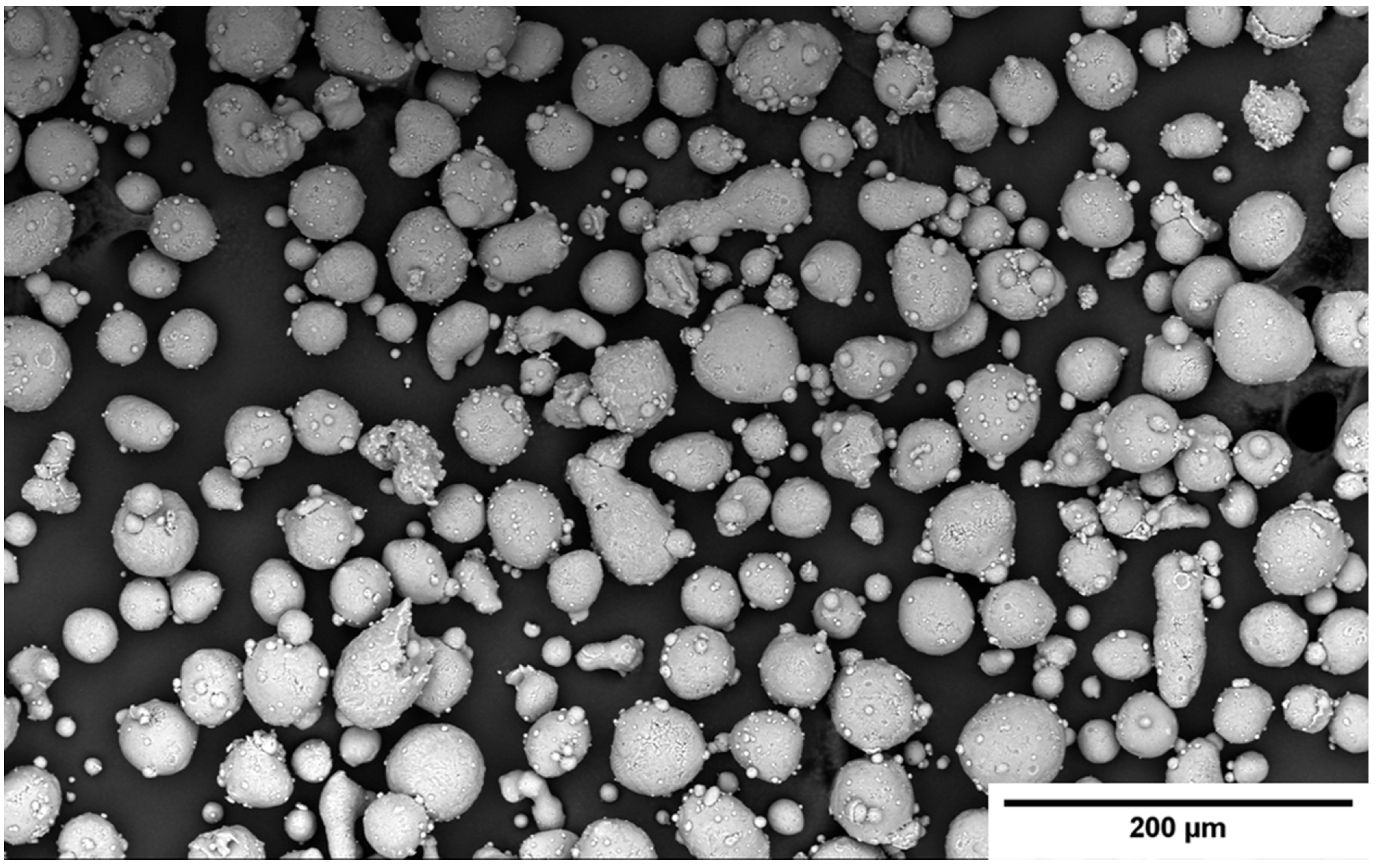
Figure 1. SEM micrograph of AlSi10Mg metal powder.
Metals 15 00890 g001
Figure 2. Illustration of cubic samples, and the XY (transverse to build direction) and XZ (parallel to build direction) cross-sectional planes obtained from sectioning each cube. The dashed red lines within the cube represent the cutting planes, and the resulting cross-sections are shown to the right of the cube, corresponding to the XY and XZ planes.
Metals 15 00890 g002
Figure 3. Microstructures of AlSi10Mg alloy produced via LPBF: (a) XY and (b) XZ planes in the AB, after (c) SA and (d) SA&AA conditions. Yellow arrows indicate the α-Al matrix and red arrows the eutectic Si networks (AB) and Si particles (SA and SA&AA). EDS spectra are provided for each microstructural feature indicated by yellow and red arrows.
Metals 15 00890 g003
Figure 4. Optical micrographs illustrating microhardness indent arrays on XY and XZ planes of (a), (d) AB and (b,c,e,f) heat-treated (SA, SA&AA) samples. The scale bar is 100 μm for all micrographs.
Metals 15 00890 g004
Figure 5. Maximum indentation load versus contact depth for AlSi10Mg samples in (a,b) the as-built condition, (c,d) after SA, and (e,f) after SA&AA, across both XY and XZ planes.
Metals 15 00890 g005
Figure 6. Hardness (gray square) and elastic modulus (red diamonds) as function of contact depth for AlSi10Mg alloy (a,b) as built, (c,d) upon SA, and (e,f) SA&AA, across XY and XZ planes.
Metals 15 00890 g006
Figure 7. SEM images of the AB state in (a) XY and (b) XZ planes, each displaying two square-marked indent locations. The corresponding load–displacement curves are shown in (c) and (d), respectively. Curve colors match the border colors of the indent boxes in the SEM images.
Metals 15 00890 g007
Figure 8. SEM images of nanoindentation imprints on the XY plane for (a) AB, (b) SA, and (c) SA&AA conditions, each showing two square-marked indent locations. EDS elemental maps for (d,g,j) AB; (e,h,k) SA; and (f,i,l) SA&AA conditions. The top row (df) shows combined Al (yellow) + (Si) (green) overlays, while the middle (gi) and bottom (jl) rows show the individual Al and Si elemental distributions, respectively. Load–displacement curves corresponding to these indent locations are shown in (m) for AB, (n) for SA, and (o) for SA&AA. Curve colors match the border colors of the indent boxes in the SEM images.
Metals 15 00890 g008
Figure 9. EDS maps of SA&AA condition in (a) XY and (b) XZ planes, with insets showing magnified indent locations. Yellow indicates Al and green indicates Si. The associated load–displacement curves are shown in (c,d), respectively. Curve colors correspond to the border colors of the indent boxes in the EDS maps.
Metals 15 00890 g009
Figure 10. Hardness contour plots of AlSi10Mg for (a,b) as-built, (c,d) SA, and (e,f) SA&AA conditions across XY and XZ planes. To ease the comparison, the range of the scale bars is the same for each map.
Metals 15 00890 g010
Figure 11. Elastic modulus contour plots of AlSi10Mg samples for (a,b) as-built, (c,d) SA, and (e,f) SA&AA conditions across XY and XZ planes. To ease the comparison, the range of the scale bars is the same for each map.
Metals 15 00890 g011
Table 1. Chemical composition of AlSi10Mg metal powder feedstock.
AlSi10Mg
AlCuFeMgMnNiPbSiSnTiZn
Balance<0.010.140.37<0.01<0.01<0.019.8<0.010.010.01
Table 2. Summarized microhardness results for all three conditions and planes.
AlSi10MgXY PlaneXZ Plane
AB127.68 ± 3.54 HV0.5125.02 ± 2.10 HV0.5
SA68.07 ± 1.25 HV0.569.23 ± 1.30 HV0.5
SA&AA83.25 ± 1.48 HV0.583.72 ± 1.51 HV0.5
Table 3. Hardness and elastic modulus (GPa) of AlSi10Mg measured via nanoindentation on XY and XZ planes under as-built, SA, and SA&AA conditions.
ConditionPlaneHardness (GPa)Elastic Modulus (GPa)
ABXY1.94 ± 0.0975.4 ± 1.6
XZ2.01 ± 0.0865.9 ± 2.5
SAXY1.42 ± 0.2283.2 ± 6.0
XZ1.35 ± 0.1664.6 ± 3.3
SA&AAXY1.55 ± 0.2155.2 ± 2.7
XZ1.61 ± 0.2464.4 ± 3.8
Disclaimer/Publisher’s Note: The statements, opinions and data contained in all publications are solely those of the individual author(s) and contributor(s) and not of MDPI and/or the editor(s). MDPI and/or the editor(s) disclaim responsibility for any injury to people or property resulting from any ideas, methods, instructions or products referred to in the content.