Abstract
In this paper, the different effects of laser shock peening (LSP) and laser shock peening without coating (LSPwC) on the morphology, microhardness and fretting-wear behavior of DD6 Ni-based single-crystal superalloy are investigated. The results show that the surface roughness of DD6 decreases slightly after LSP, while it increases after LSPwC due to surface remelting. Shock wave strengthening during LSP and LSPwC results in plastic deformation of the surface layer of DD6 samples. However, besides work hardening from shock wave, dispersion strengthening of oxide particles also occurs during LSPwC. Therefore, after LSPwC, the microhardness of the DD6 surface layer increases by 38.8%, higher than the increase of 27.7% after LSP. The fretting wear resistance of DD6 increases by about 42.8% and 58% after LSP and LSPwC, respectively. The surface roughness only affects the friction coefficient at the initial stage of fretting wear. The hardness increase caused by work hardening and the dispersion strengthening of surface oxides after laser strengthening is the key to the improvement of fretting wear resistance. The main wear mechanisms of untreated and LSP sample are oxidation wear, abrasive wear and adhesive wear, while the main wear mechanisms of LSPwC sample are oxidation wear and adhesive wear.
1. Introduction
Single-crystal superalloy such as DD6 is regarded as ideal material for manufacturing advanced aero-engine turbine blades due to its excellent fatigue resistance and creep resistance at high temperature [1,2]. However, the turbine blade tenon is prone to fretting damage under cyclic loading and high-frequency vibration conditions [3,4], which greatly reduces the service life of single-crystal blades [5,6,7]. Therefore, improving the fretting wear performance of single-crystal superalloy is of great significance to ensure aviation safety.
Since the wear properties of materials are often closely related to the state of the material surface, surface strengthening treatments such as shot peening (SP) and laser shock processing (LSP) are performed to effectively improve the fretting wear resistance of materials [8,9]. LSP is a kind of surface strengthening treatment which has been successfully applied to the surface modification of key engine components in recent years [10,11]. During the process of LSP, the plastic deformation layer, hardening layer and residual compressive stress layer are formed on the surface of the material by using high energy laser beam to irradiate the metal surface, improving the wear resistance, corrosion resistance and fatigue life of materials [12,13]. However, the necessity to apply and remove protective layers before and after the impact significantly increases both time and economic costs, particularly for the complex geometries of blade tenons, which further complicates the process. Laser shock peening without coating (LSPwC) eliminates the need for a protective layer, as the laser directly interacts with the surface of the material being strengthened. To minimize laser ablation on the surface and reduce the increase in surface roughness, LSPwC typically employs millijoule-level energy and spot sizes of several hundred micrometers [14]. Consequently, LSPwC is more suitable for strengthening components with intricate shapes [15]. Compared with the pure force strengthening effect of LSP, LSPwC is strengthened by mechanical-thermal coupling.
Many studies have focused on the surface microstructure evolution and property improvement of LSP-treated single-crystal superalloy. Hu et al. [16] found that pits appeared on the surface of single-crystal superalloy after LSP, resulting in plastic deformation, and the surface residual stress and hardness increased. Based on this, Lu et al. [13,17,18] found that the pits after peening were formed by the interaction between γ and γ′ phases after compression. Rozmus et al. [9] found staggered slip bands and high-density dislocations in the near-surface layer of single-crystal superalloy after LSP. He et al. [14,19,20] studied the microstructure and mechanical properties of superalloy K24 after LSPwC. However, there are few studies on the surface microstructure of LSPwC-treated single-crystal superalloy. In contrast, in enhancing the fretting wear resistance of materials, Zhang et al. [8] and Yin et al. [21] found that the surface of titanium alloy was hardened and residual stress was generated after LSP. Therefore, the fretting wear performance of titanium alloy was effectively improved. Lu et al. also found that surface peening technology can effectively improve the fretting wear performance of aero-engine titanium alloy turbine blade tenon [22]. Current research on LSP and LSPwC for enhancing resistance to fretting wear primarily focuses on polycrystalline materials. However, there are limited studies addressing fretting wear following the strengthening of single-crystal superalloys. Notably, comparative research on the effects of LSP and LSPwC on the fretting wear of single-crystal superalloys remains scarce.
In this study, the near-surface morphology and mechanical properties of DD6 were analyzed. The effects of two strengthening methods on fretting wear performance were evaluated by fretting wear test. The wear mechanism was analyzed in terms of fretting wear running state and wear scar.
2. Materials and Methods
2.1. Materials
The material used in this study was nickel-based DD6 single-crystal superalloy with a chemical composition shown in Table 1 (in wt.%). The basic elements include Ni, Co, W, Ta, Al, Cr, Re, Mo, Nb and Hf. The alloy was heat-treated at 1250 °C for 4 h followed by air cooling. The growth direction of DD6 was [001]. The microstructure of DD6 was composed of γ phase and γ′ phase, as shown in Figure 1.

Table 1.
The chemical composition of DD6 single-crystal superalloy (Wt.%).
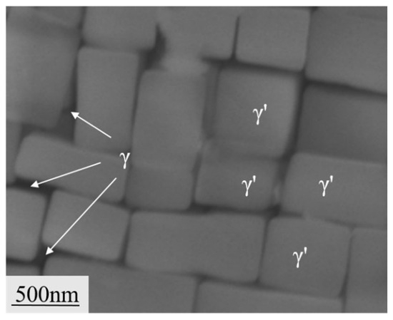
Figure 1.
Microstructure of DD6 single-crystal superalloy.
2.2. Experimental Procedure
DD6 raw material was processed into 30 mm × 20 mm × 2 mm blocks by wire cutting machine. The surface of DD6 was polished with sandpaper until Ra was about 0.8 μm as measured by a profilometer, in order to imitate the grinding pretreatment of the tenon. The polished samples were sonicated for 5 min in absolute alcohol to remove surface contaminants.
DD6 samples were subjected to LSP and LSPwC treatments, respectively. The parameters are shown in Table 2. The LSP was performed with a YS100-R200A laser system (Xi’an Tianruida Optoelectronics Technology Co., Ltd., Xi’an, China), whereas the LSPwC was carried out using a YSM2000-C30A laser system (Xi’an Tianruida Optoelectronics Technology Co., Ltd., Xi’an, China). LSP used black tape as the protective layer and flowing water as the confinement layer. LSPwC had no protective layer, and the confinement layer was flowing water. The strengthening methods of LSP and LSPwC are illustrated in Figure 2.

Table 2.
Parameters of LSP and LSPwC.
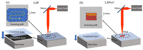
Figure 2.
The strengthening methods of LSP and LSPwC: (a) Schematic illustration of LSP, (b) Schematic illustration of LSPwC.
2.3. Characterization Methods
The microstructure results of DD6 near-surface were analyzed by field emission scanning electron microscope (GeminiSEM 500, Carl Zeiss AG, Oberkochen, Germany). Chemical composition and electron backscatter diffraction results were characterized by EDS and EBSD probes. The 3D morphology and roughness of the samples were measured by laser confocal microscopy (OLS4000, Olympus, Tokyo, Japan). The hardness of DD6 near-surface was characterized by Micro Vickers hardness tester (HXD-1000TMC, Shanghai Shangming Optical Instrument Co., Ltd., Shanghai, China). The load was 200 g and the holding time was 15 s. Three lines of microhardness profiles were collected along the peening direction, and the measurements at the same depth were averaged. For the fretting wear test, a tangential fretting wear testing machine was used with a GCr15 ball as the wear pair. The load was 20 N, the displacement amplitude was ±100 μm, the frequency was 10 Hz, and the number of cyclic was 105. The effects of LSP and LSPwC on fretting wear properties of DD6 were studied by scanning electron microscope and laser scanning confocal microscope.
3. Results and Discussion
3.1. Surface Morphology
The surface roughness Ra of DD6 after different treatments was measured by laser confocal microscope. Figure 3 shows the results of the surface roughness of DD6 after different treatments. The average surface roughness Ra of untreated DD6 is 0.89 μm after LSP, the Ra decreases to 0.72 μm, a reduction of 19.1% compared with untreated DD6. In contrast, after LSPwC, the Ra increases to 1.73 μm, an increase of 94.4% compared with untreated DD6. The above results indicate that both laser strengthening methods change the surface roughness of DD6.
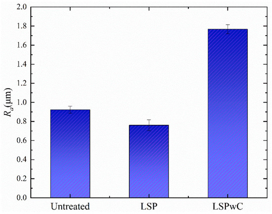
Figure 3.
Surface roughness Ra of untreated, LSP and LSPwC samples.
To investigate the reasons for the surface roughness change of DD6 after different strengthening, the surface structure and element composition are analyzed. Figure 4a–f show the 3D surface morphology and SEM image of the untreated and strengthened sample. The untreated and LSP-treated DD6 surface still has the scratches from the grinding pretreatment, but the LSP sample has shallower scratches and slightly lower roughness. The surface of the sample is subjected to stress wave impact by LSP, and then undergoes plastic deformation. Therefore, γ and γ′ phases deform differently, and γ′ phase emerges. After LSP, protrusions of the γ′ phase are observed in localized regions on the alloy surface. This phenomenon arises because repeated laser impacts drive transverse plastic flow toward saturation, causing the constrained regions to form upward protrusions. As a strengthening phase, the γ′ phase plays a more critical role than the γ phase during LSP-induced plastic deformation [23]. When both γ channels and γ′ phase approach a “saturated” state in transverse plastic deformation, further lateral deformation of the material becomes severely restricted. Subsequently, under the intense compressive stress field, longitudinal expansion occurs preferentially along the γ′ phase, ultimately generating surface protrusions. Lu also observed a similar phenomenon [18,23]. Statistical analysis of the sizes of the two phases before and after LSP revealed that the γ′ phase exhibited an increase in size, while the γ channels became narrower. This observation supports the proposed mechanism of γ′ phase extrusion toward the surface. After LSPwC, the DD6 surface structure changes significantly, the grinding scratches disappear, and microporous structure appears on the surface. We used EDS spectrometer to conduct micro-element analysis of the strengthened surface, and Figure 4g–i show the results. EDS surface scanning analysis indicates that the surface element content after LSP resembles that before treatment. However, after LSPwC treatment, the surface O content increases sharply, by 91.7%. This is attributed to the lack of a protective coating on the material surface during the LSPwC process, which leads to oxidation and remelting of the material surface.
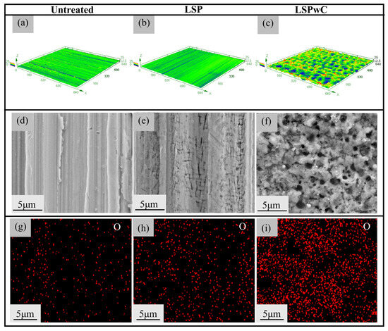
Figure 4.
Three-dimensional morphology, SEM image and EDS results of O element on the surface of untreated and LSP, LSPwC samples: (a–c) three-dimensional morphology, (d–f) SEM image, (g–i) EDS result of O element.
In order to further explore the element distribution of DD6 surface remelting layer after LSPwC, the elemental composition of the material surface was analyzed by EDS spectrometer. The results are shown in Figure 5. It can be seen that there are areoxide particles on the surface of DD6 after LSPwC. Oxide particles and matrix areas are marked as points 1 and 2. The content of each element in points 1 and 2 is shown in Figure 5b. The results show that the content of O, Al and Cr increases and the content of Ni decreases in the element distribution of oxide particles compared with the matrix region. It shows that in the absence of an absorbing protective layer, Al and Cr elements in the γ and γ′ phases on the surface of the DD6 after LSPwC precipitate to form oxides, forming a large number of oxide particles. The Al and Cr elements in the γ and γ ‘ phases of DD6 form a large number of alumina and chromium oxide particles with a size of 30–200 nm. The oxide particles formed during the remelting process are dispersed on the strengthened surface, with high hardness and strength, resulting in dispersion strengthening, which can effectively improve the surface hardness of the DD6.

Figure 5.
Elemental analysis of two points on the surface of DD6 after LSPwC. (a) SEM image of the remelting layer; (b) element contents of the oxide particles and the matrix region (EDS point scan).
LSP strengthens the material by forming a shock wave that applies a dynamic mechanical effect on the material surface. This causes plastic deformation on the material surface [24]. After that, the grinding scratches on the material surface decrease and the roughness reduces slightly. LSPwC does not have an absorption protective layer, so the laser thermal effect ablates and remelts the surface material [25]. Al and Cr-rich oxide particles form on the DD6 surface, leading to dispersion strengthening. During the strengthening, the DD6 single-crystal surface material undergoes a phase change and gasifies to become a plasma that generates a shock wave to propagate inside the material [26]. Therefore, the ablated surface forms a microporous structure and the roughness increases significantly.
3.2. Near-Surface Morphology
The morphology and roughness of the DD6 single-crystal surface changed after LSP and LSPwC strengthened the surface of the material. The microstructure along the depth direction of the section also deformed. Then, the field emission scanning electron microscope characterized the microstructure of the surface layer of the cross section of the strengthened DD6 single-crystal superalloy. Figure 6 shows the results. The γ′ phase on the surface of DD6 single-crystal superalloy deforms or even breaks obviously after LSP, as Figure 6a shows. As Figure 6b shows, a discontinuous remelting layer with a thickness of about 1 μm appears on the DD6 surface after LSPwC. To explore the element distribution of the remelted layer, energy spectrum surface scanning further characterized the remelted layer. Figure 6c shows the results. The remelting layer is enriched in Cr, Al and O and depleted in Ni. This is also consistent with the previous study of surface element distribution.
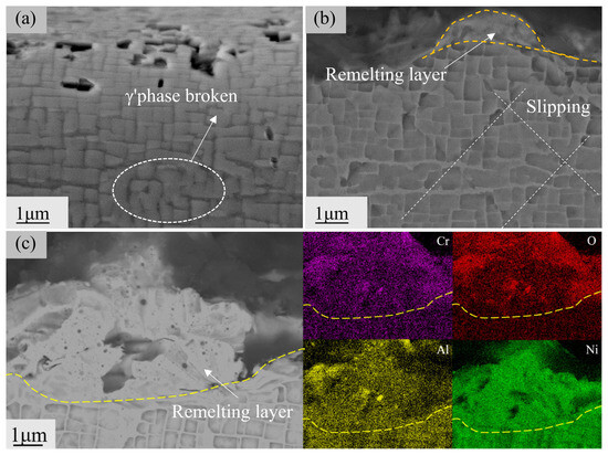
Figure 6.
SEM images of DD6 cross-section surface after LSP and LSPwC: (a) micromorphology cross section after LSP, (b) micromorphology cross section after LSPwC, (c) the element distribution section remelting layer after LSPwC.
The microstructures of LSP and LSPwC at different depths (2 μm, 20 μm, 50 μm, 100 μm) from the surface are characterized to study the deformation mechanism of DD6 near-surface. Figure 7a–d show the microstructure of DD6 cross section after LSP. The γ′ phase at 2 μm from the surface loses its original cubic structure due to severe plastic deformation or even breakage caused by laser shock, as Figure 7a shows. The γ′ phase is the strengthening phase of single-crystal superalloy, and its breakage may affect the surface mechanical properties of DD6 single-crystal superalloy [27]. As Figure 7b shows, a large number of staggered slip bands appear at 20 μm from the surface. The slip bands gradually decrease as the depth increases, and a small amount of slip bands still exist at 100 μm, as Figure 7d shows. Figure 7e–h shows the microstructure of DD6 cross section after LSPwC. The γ′ phase at 2 μm from the surface is deformed but not broken. It still maintains cubic structure. There are staggered slip bands at the surface, as indicated by the white dotted line in Figure 7e. Then, with the increase in depth, the slip band decreases gradually. The staggered slip band becomes a unidirectional slip band gradually, and no slip band appears at 100 μm, as Figure 7h shows.
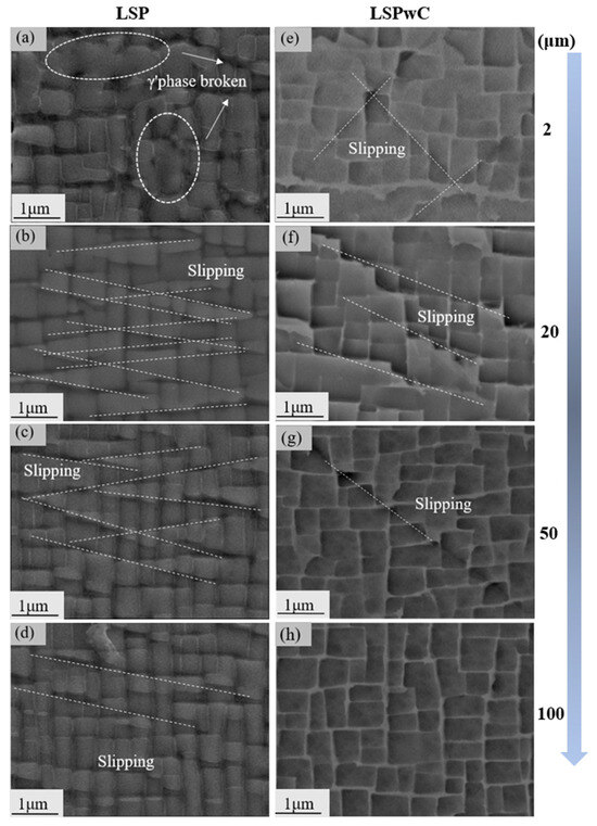
Figure 7.
SEM images of DD6 cross section at different depths from surface after strengthening: (a–d) the microstructure at 2–100 μm from the surface after LSP; (e–h) the microstructure at 2–100 μm from the surface after LSPwC.
To obtain the surface geometric dislocation density and deformation degree, the cross section of the strengthened single-crystal superalloy DD6 is characterized by EBSD probe. The orientation of grains in the Y direction is reflected by the IPF-Y diagram [28]. As Figure 8a,c show, no grain boundary is found and it is still a single-crystal structure after strengthening, although plastic deformation occurs in the near-surface layer of DD6. The degree of plastic deformation and misorientation is evaluated by KAM diagram. The higher the degree of plastic deformation and orientation error, the higher the KAM value [29]. As Figure 8b,d show, the deformation law of the near-surface layer of DD6 after strengthening is the same. The degree of plastic deformation decreases gradually from the impact surface along the depth direction, and so does the geometric dislocation density. The cumulative orientation difference of the surface material along the arrow direction in Figure 8b,d is extracted in Figure 8e to further quantify the geometric dislocation density of the surface layer of the strengthened single-crystal superalloy. It can be concluded that from the strengthening surface along the depth direction of 200 μm, the maximum accumulative orientation difference of DD6 after LSP is 1.7°, while that after LSPwC is 1.26°. The cumulative misorientation increases with depth. From the results of misorientation, it can be seen that compared with LSPwC sample, the deformation depth of LSP sample is greater. However, in the surface 50 μm, LSPwC has larger dislocation density.
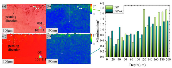
Figure 8.
EBSD results of DD6 cross section after strengthening: (a) IPF-Y diagram of cross section after LSP; (b) KAM diagram of cross section after LSP; (c) IPF-Y diagram of cross section after LSPwC; (d) KAM diagram of cross section after LSPwC; (e) the cumulative orientation difference of 200 μm depth along the white arrow direction in the KAM image.
Previous studies have shown that the shock wave generated during LSP causes plastic deformation on the surface of DD6, thus forming a plastic deformation layer. In this process, due to the high lattice dislocation energy of the γ′ phase, dislocation entanglement first appears at the γ phase. When the stress concentration reaches the strength of the γ′ phase, dislocations will enter the γ′ phase [13,28]. Moreover, a large number of dislocation tangles can cut into the γ′ phase to form a slip band [26]. Therefore, the results of EBSD are consistent with the previous SEM results at different depths. After LSP, the surface layer of the single-crystal superalloy appears as the phenomenon of γ′ phase breaking, there is no slip band, and the geometric dislocation density is small, in the range of 50 μm. The surface layer of single-crystal superalloy after LSPwC is staggered slip band. The geometric dislocation density of LSPwC sample is larger than that of LSP sample in the range of 50 μm. Compared with LSPwC, the surface deformation layer of LSP strengthened DD6 single-crystal is deeper.
3.3. Near-Surface Microhardness
After-strengthening DD6 cross-section near-surface micro-Vickers hardness is shown in Figure 9. It can be observed that for all samples, the surface hardness is the largest and gradually decreases with increasing depth, to the matrix hardness changes tend to be gentle. The maximum hardness of the near-surface layer after LSP is 568.2 HV, while that after LSPwC is 617.6 HV. Compared with the average hardness of 450 HV of the untreated DD6 in the blue line of Figure 9, the maximum surface hardness of DD6 after LSP and LSPwC strengthening is increased by 27.7% and 38.8%, respectively. The microhardness of LSPwC sample is higher than that of LSP sample in the depth of about 100 μm. The depth of hardened layer after LSP is 1397 μm, and the depth of hardened layer after LSPwC is 497 μm. Because the LSPwC sample surface has both work hardening and dispersion strengthening and the LSP laser energy is large, the near-surface hardness of DD6 is higher after LSPwC, while the hardened layer is deeper after LSP. The higher surface hardness of DD6 after LSPwC strengthening compared with LSP strengthening is attributed to the combined effects of work hardening and dispersion strengthening in the LSPwC process. Meanwhile, the larger laser energy used in LSP induces a deeper work-hardened layer.
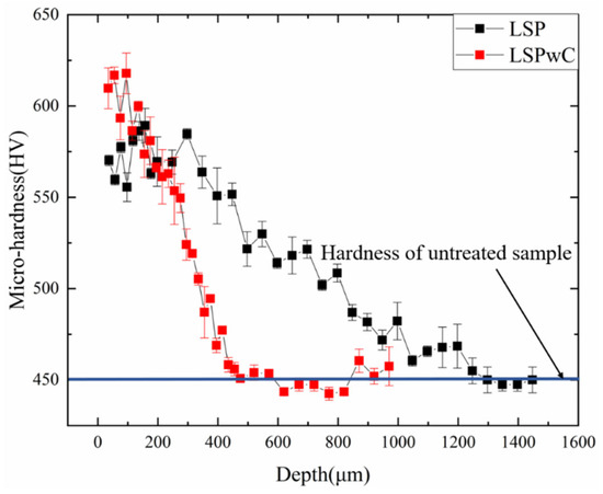
Figure 9.
Hardness distribution of DD6 near-surface layer along depth direction after LSP and LSPwC.
3.4. Fretting Wear Characteristics
In the fretting wear test, the friction-displacement curves (F-D curves) is an important dynamic parameter to characterize the fretting wear process, which can effectively reflect the fretting state [30]. The F-D curves of untreated and strengthened DD6 samples are shown in Figure 10. The fretting state of untreated and strengthened samples is consistent. Firstly, the F-D curve is obviously parallelogram at the beginning of operation, which indicates that the fretting state is in the partial slip regime. After that, with the increase in fretting wear cycles, the F-D curve gradually changes from a parallelogram to an oval, which indicates that the fretting state changed from a complete slip zone to a mixed regime. Finally, in stable operation, the F-D curve is oval, fretting in the mixed regime. Among them, the F-D curves of the sample after LSPwC have the smallest number of cycles from parallelogram to ellipse, and the transition cycles of the untreated sample and the sample after LSP are similar. It can be seen from the previous study that the surface of DD6 after LSPwC shows oxidation-remelting phenomenon, and the surface roughness increases compared with the untreated sample. The change in roughness affects the fretting state in the early stage of fretting wear, which makes the transition cycle of LSPwC sample from partial sliding to mixed smaller. Although the surface roughness of the untreated sample is slightly lower than that of the LSP sample, they are essentially consistent, so the fretting wear running state is consistent. The roughness only affects the fretting wear running state before 200 cycles but has no effect on 200 to 105 cycles.
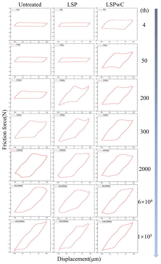
Figure 10.
F-D curves of DD6 fretting wear in different cycles after LSP and LSPwC.
As shown in Figure 11a, the wear scar profiles of untreated and strengthened samples are characterized by laser confocal microscopy. It is found that the wear scar depth and width of untreated samples are larger than that of strengthened samples. Because of the accumulation and compaction of the wear debris in the wear scar, the cross section of the wear scar has a concave and convex phenomenon. The wear rates of untreated, LSP and LSPwC samples are 6.1 × 105 μm3/mN, 3.5 × 105 μm3/mN, 2.5 × 105 μm3/mN, as shown in Figure 11b. Compared with the untreated sample, the fretting wear resistance of the strengthened sample increased by 42.8% and 59.7%, respectively. The fretting wear resistance of DD6 single-crystal superalloy after LSPwC is better.
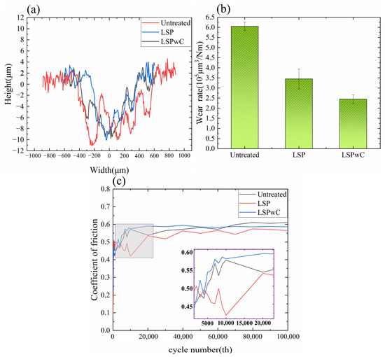
Figure 11.
Fretting wear results of strengthened and untreated specimens: (a) the wear scar cross-section morphology; (b) the wear rate; (c) friction coefficient—local enlarged image is the friction coefficient in the initial stage of fretting wear.
The wear rate of the two strengthening methods decreased. This is due to the formation of plastic deformation layer and hardening layer on the surface of single-crystal superalloy after strengthening. The dislocation and slip phenomena on the surface of DD6 increase the hardness of the surface layer, thus increasing the wear resistance of DD6. It can be seen from the previous results that the dislocation density and microhardness of the LSPwC sample within 50 μm are greater than those of the LSP sample. The depth of fretting wear scar is about 10 μm, as shown in Figure 11a. This explains why the fretting wear performance of LSPwC sample is better than that of LSP.
The friction coefficient changing with the number of cycles is shown in Figure 11c. The variation trend of friction coefficient of untreated and strengthened samples is the same. The friction coefficient is small at the beginning of fretting wear. With the increase in adhesion, the friction coefficient increases gradually and finally tends to be stable. The average friction coefficients of untreated, LSP and LSPwC are 0.59, 0.55 and 0.57, respectively. As shown in the local enlarged image, due to the increase in surface roughness after LSPwC, the friction coefficient is the largest at the initial stage of fretting wear. However, with the increase in fretting wear cycles, the friction coefficient of untreated samples in the stable operation stage is the largest, and the friction coefficients of the three samples are similar. Like the previous research results of fretting wear, the change in roughness only affects the friction coefficient and wear state within 200 cycles of fretting wear. After 200 to 105 cycles of fretting wear operation, the friction coefficient and wear state of the two strengthened samples and the untreated samples are consistent.
The fretting state of the untreated and strengthened DD6 are similar. Firstly, the friction coefficient is lower. The fretting state is in the partial slip regime. After that, with the increase in viscosity, it gradually changes to the mixed regime, and the friction coefficient gradually increases. In the final stable operation stage, the fretting wear state is mixed regime, and the friction coefficient is stable at a fixed value. The surface roughness increases due to the existence of remelted layer after LSPwC, while the surface roughness of untreated sample is similar to that after LSP. Therefore, the friction coefficient of the sample after LSPwC is larger at the initial stage of friction, and the number of cycles during the transition from partial sliding to mixing is smaller. After the stable stage, the fretting state and friction coefficient of the three samples are similar. It shows that roughness only affects the friction coefficient at the initial stage of fretting wear. The concave and convex morphology of the surface is removed at the initial stage of wear. With the decrease in roughness, the friction coefficient gradually tends to be consistent. Under stable operation, the friction coefficients of the three samples are similar, indicating that the wear reduction performance of the DD6 surface is not significantly improved after strengthening [31].
The wear scar morphology of the untreated and strengthened samples is analyzed, as shown in Figure 12. The wear scar morphology of the untreated specimen is shown in Figure 12a. The wear debris accumulates and compacts at the center of the wear scar to form an interface. The wear debris at the center of the wear scar is oxidized to form a black product. There are furrows along the fretting direction and spalling pits due to adhesion in the grinding marks. The wear scar morphology of the sample after LSP is shown in Figure 12b. There are also phenomena of wear debris oxidation, adhesive peeling and fretting plowing, but the accumulation of wear debris and the oxidation wear debris on the surface of the sample after LSP are reduced. The wear scar morphology of the sample after LSPwC is shown in Figure 12c. There are obvious spalling pits, but there is no obvious oxidation wear debris and fretting plowing phenomenon. The wear scar edge is less worn, and the wear scar boundary is not obvious [32,33].

Figure 12.
SEM images of fretting wear scars of untreated and strengthened DD6: (a) Untreated sample, (b) LSP sample, (c) LSPwC sample.
After that, the micro-area composition analysis of the wear marks of the untreated and strengthened samples is carried out, as shown in Figure 13. It can be seen that the O content and Fe content in the debris accumulation area of the untreated and LSP samples increase significantly, and the Ni content decreases. The increase in O content indicates that the wear debris is oxidized during the fretting wear operation. The increase in Fe content indicates that the element exchange occurs between the grinding pair and the sample due to the adhesion. The content of O and Fe in the debris accumulation area of LSPwC sample increase, and oxidative wear and adhesive wear also occur. However, due to the remelting layer on the surface after strengthening, the Ni content of the whole surface is smaller than that of the untreated sample.
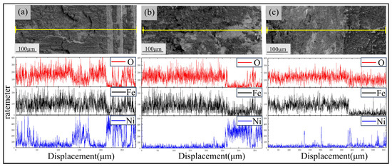
Figure 13.
EDS results of Ni, O and Fe elements in the wear scars of untreated and strengthened DD6 wear scars: (a) Untreated sample, (b) LSP sample, (c) LSPwC sample.
As shown in Figure 12, both the untreated and LSP-treated samples exhibit oxide debris, adhesive spalling, and plowing on the fretting wear scar surfaces, indicating that LSP does not appreciably alter the fretting-wear mechanism of DD6. However, there is no obvious furrow caused by abrasive wear on the fretting wear scar surface of the LSPwC sample, so there is no obvious abrasive wear in the wear mechanism of LSPwC. This is attributed to the higher hardness of the LSPwC-treated DD6 within the shallow depth (<15 μm), which provides greater resistance to abrasive wear and thereby suppresses it for the LSPwC-treated samples. Due to the effect of adhesive wear mechanism, all samples have element exchange with the grinding pair. Therefore, the results of comprehensive wear scar morphology and elemental analysis show that the wear mechanism of the untreated sample is severe oxidation wear, adhesive wear and slight abrasive wear. The wear mechanism of the sample after LSP is oxidation wear, adhesive wear and slight abrasive wear. The wear mechanism of the sample after LSPwC is oxidation wear and adhesive wear.
4. Conclusions
In this paper, LSP and LSPwC are used to strengthen DD6 single-crystal superalloy. The effects of two methods on the surface morphology, mechanical properties and fretting wear properties of DD6 superalloy are studied. The analysis draws the following conclusions:
- Due to the shock wave, plastic deformation occurs in the near-surface layer after LSP and LSPwC. High-density dislocations are formed and a slip phenomenon occurs. The deformation layer of the LSP sample is deeper, but the geometric dislocation density of LSPwC sample is larger in the near-surface 50 μm. The ablation and oxidation phenomenon occur on the surface after LSPwC, resulting in a microporous structure, forming a remelting layer of about 1 μm, and the roughness increases. There are a large number of nano-sized oxide particles in the remelted layer form dispersion strengthening.
- Compared with the untreated sample, the fretting wear resistance of DD6 after LSP and LSPwC strengthening increased by 42.8% and 59.7%, respectively. This is due to the formation of a hardened layer by strengthening, which improves the wear resistance of the surface. Work hardening and dispersion strengthening exist simultaneously after LSPwC, so the hardness and wear resistance are better. The change in roughness only affects the initial friction coefficient and has no obvious effect on the friction coefficient after stable operation.
- Compared with LSP, the maximum surface hardness of LSPwC is higher. The increase in hardness alleviates the abrasive wear caused by chip cutting and improves the plowing resistance of the material. Therefore, the wear mechanism of untreated sample and sample after LSP is adhesive wear, abrasive wear and oxidation wear; while the wear mechanism of LSPwC treated DD6 is oxidation wear and adhesive wear.
Author Contributions
Conceptualization, Y.L., X.D., S.L., L.Z., X.L. and W.H.; methodology, Y.L., L.Q., X.D., M.L. and S.L.; validation, Y.L.; formal analysis, Y.L., X.D. and L.Z.; resources, S.L., X.L. and W.H.; data curation, L.Q. and M.L.; writing—original draft preparation, Y.L.; writing—review and editing, L.Q., X.D. and X.L.; visualization, Y.L. and L.Q.; supervision, S.L., L.Z., X.L. and W.H. All authors have read and agreed to the published version of the manuscript.
Funding
This research was supported by the National Natural Science Foundation of China (52375225, 92360307) and the National Science and Technology Major Project of China (J2019-III-0008-0051, J2019-IV-0003-0070).
Data Availability Statement
The original contributions presented in this study are included in the article. Further inquiries can be directed to the corresponding authors.
Conflicts of Interest
The authors declare that they have no known competing financial interests or personal relationships that could have appeared to influence the work reported in this paper.
References
- Su, Y.; Han, Q.N.; Zhang, C.C.; Shi, H.J.; Niu, L.S.; Deng, G.J.; Rui, S.S. Effects of secondary orientation and temperature on the fretting fatigue behaviors of Ni-based single crystal superalloys. Tribol. Int. 2019, 130, 9–18. [Google Scholar] [CrossRef]
- Sun, S.; Li, L.; Yang, W.; Yue, Z.; Wan, H. RA-based fretting fatigue life prediction method of Ni-based single crystal superalloys. Tribol. Int. 2019, 134, 109–117. [Google Scholar] [CrossRef]
- Araujo, J.A.; Nowell, D. Mixed high low fretting fatigue of Ti6Al4V: Tests and modelling. Tribol. Int. 2009, 42, 1276–1285. [Google Scholar] [CrossRef]
- Golden, P.J.; Hutson, A.; Sundaram, V.; Arps, J.H. Effect of surface treatments on fretting fatigue of Ti-6Al-4V. Int. J. Fatigue 2007, 29, 1302–1310. [Google Scholar] [CrossRef]
- Han, G.; Chen, Y.; Wang, X. Flutter analysis of bending-torsion coupling of aero-engine compressor blade with assembled clearance. Appl. Math. Model. 2015, 39, 2539–2553. [Google Scholar] [CrossRef]
- Xin, L.; Huang, Q.; Han, Y.M.; Lu, Y.H.; Zhang, W.D.; Shoji, T. The damage mechanism of Alloy 690TT against Alloy 600 caused by fretting wear in room temperature pure water. Mater. Charact. 2020, 161, 110176. [Google Scholar] [CrossRef]
- Amanov, A. Improvement in mechanical properties and fretting wear of Inconel 718 superalloy by ultrasonic nanocrystal surface modification. Wear 2020, 446, 203208. [Google Scholar] [CrossRef]
- Zhang, H.; Sun, Z.; Cao, Z.; Li, Z.; Zhou, W.; Fu, X. Effect of Laser Shock Peening on Fretting Wear Behavior of TB6 Titanium Alloy. Aer. Manuf. Technol. 2021, 64, 78–84, 101. [Google Scholar] [CrossRef]
- Rozmus-Górnikowska, M.; Kusiński, J.; Cieniek, Ł.; Morgiel, J. The Microstructure and Properties of Laser Shock Peened CMSX4 Superalloy. Metall. Mater. Trans. A 2021, 52, 2845–2858. [Google Scholar] [CrossRef]
- Lu, G.; Liu, J.; Qiao, H.; Cui, C.; Zhou, Y.; Jin, T.; Zhao, J.; Sun, X.; Hu, Z. The Local Microscale Reverse Deformation of Metallic Material under Laser Shock. Adv. Eng. Mater. 2017, 19, 1600672. [Google Scholar] [CrossRef]
- Srinivasan, S.; Garcia, D.B.; Gean, M.C.; Murthy, H.; Farris, T.N. Fretting fatigue of laser shock peened Ti-6Al-4V. Tribol. Int. 2009, 42, 1324–1329. [Google Scholar] [CrossRef]
- Mao, B.; Liao, Y.; Li, B. Abnormal twin-twin interaction in an Mg-3Al-1Zn magnesium alloy processed by laser shock peening. Scr. Mater. 2019, 165, 89–93. [Google Scholar] [CrossRef]
- Lu, G.X.; Liu, J.D.; Qiao, H.C.; Jin, T.; Sun, X.F. Crack appearance of a laser shock-treated single crystal nickel-base superalloy after isothermal fatigue failure. Surf. Coat. Technol. 2017, 321, 74–80. [Google Scholar] [CrossRef]
- Lang, M.; Zhou, G.; Luo, S.; Hu, S.; Zhang, H.; Li, Y.; Peng, R. Research Progress in Laser Shock Peening for Nickel-based Single Crystal Superalloys. China Surf. Eng. 2025, 1–20. [Google Scholar]
- Kaufman, J.; Racek, J.; Cieslar, M.; Minárik, P.; Steiner, M.A.; Mannava, S.R.; Vasudevan, V.K.; Sharma, A.; Böhm, M.; Brajer, J.; et al. The effect of laser shock peening with and without protective coating on intergranular corrosion of sensitized AA5083. Corros. Sci. 2022, 194, 109925. [Google Scholar] [CrossRef]
- Hu, X.; Yang, Y.; Zhao, J.; Lu, Y.; Wu, J.; Qiao, H. Surface integrity evolution of a Ni-based single crystal superalloy by laser shock peening. Appl. Surf. Sci. Adv. 2021, 6, 100183. [Google Scholar] [CrossRef]
- Lu, G.X.; Liu, J.D.; Qiao, H.C.; Zhou, Y.Z.; Jin, T.; Zhao, J.B.; Sun, X.F.; Hu, Z.Q. Surface nano-hardness and microstructure of a single crystal nickel base superalloy after laser shock peening. Opt. Laser Technol. 2017, 91, 116–119. [Google Scholar] [CrossRef]
- Lu, G.X.; Liu, J.D.; Qiao, H.C.; Zhou, Y.Z.; Jin, T.; Sun, X.F.; Hu, Z.Q. Surface topography evolution of Ni-based single crystal superalloy under laser shock: Formation of the nano-scale surface reliefs. Appl. Phys. A 2017, 123, 213. [Google Scholar] [CrossRef]
- Wang, H.; Keller, S.; Chang, Y.; Kashaev, N.; Yan, K.; Gurevich, E.L.; Ostendorf, A. Effect of laser shock peening without protective coating on the surface mechanical properties of NiTi alloy. J. Alloys Compd. 2022, 896, 163011. [Google Scholar] [CrossRef]
- Luo, K.; Sun, M.; Lu, J.; Zhang, Q.; Jiang, X.; Wang, C.; Lu, J. The effect of laser shock peening with and without coating on microstructure and electrochemical corrosion behavior of AZ31b magnesium alloy. Surf. Coat. Technol. 2025, 496, 131709. [Google Scholar] [CrossRef]
- Yin, M.; Wang, W.; He, W.; Cai, Z. Impact-Sliding Tribology Behavior of TC17 Alloy Treated by Laser Shock Peening. Materials 2018, 11, 1229. [Google Scholar] [CrossRef] [PubMed]
- Lu, G.; Liu, H.; Lin, C.; Zhang, Z.; Shukla, P.; Zhang, Y.; Yao, J. Improving the fretting performance of aero-engine tenon joint materials using surface strengthening. Mater. Sci. Technol. 2019, 35, 1781–1788. [Google Scholar] [CrossRef]
- Lu, G.; Liu, J.; Qiao, H.; Zhou, Y.; Jin, T.; Sun, X.; Hu, Z. Nonuniformity of morphology and mechanical properties on the surface of single crystal superalloy subjected to laser shock peening. J. Alloys Compd. 2016, 658, 721–725. [Google Scholar] [CrossRef]
- Montross, C.S.; Wei, T.; Ye, L.; Clark, G.; Mai, Y.W. Laser shock processing and its effects on microstructure and properties of metal alloys: A review. Int. J. Fatigue 2002, 24, 1021–1036. [Google Scholar] [CrossRef]
- Wang, H.; Kalchev, Y.; Wang, H.; Yan, K.; Gurevich, E.L.; Ostendorf, A. Surface modification of NiTi alloy by ultrashort pulsed laser shock peening. Surf. Coat. Technol. 2020, 394, 125899. [Google Scholar] [CrossRef]
- Geng, Y.; Mo, Y.; Zheng, H.; Li, G.; Wang, K. Effect of laser shock peening on the hot corrosion behavior of Ni-based single-crystal superalloy at 750 °C. Corros. Sci. 2021, 185, 109419. [Google Scholar] [CrossRef]
- Long, H.; Mao, S.; Liu, Y.; Zhang, Z.; Han, X. Microstructural and compositional design of Ni-based single crystalline superalloysd—A review. J. Alloys Compd. 2018, 743, 203–220. [Google Scholar] [CrossRef]
- Fang, Y.; Zhao, S.; Yang, L.; Wang, Y. Effect of laser impacts on the fatigue properties of DD6 alloy. Optik 2016, 127, 11094–11101. [Google Scholar] [CrossRef]
- Zhang, H.; Ren, Z.; Liu, J.; Zhao, J.; Liu, Z.; Lin, D.; Zhang, R.; Graber, M.J.; Thomas, N.K.; Kerek, Z.D.; et al. Microstructure evolution and electroplasticity in Ti64 subjected to electropulsing-assisted laser shock peening. J. Alloys Compd. 2019, 802, 573–582. [Google Scholar] [CrossRef]
- Ming, H.; Liu, X.; Lai, J.; Wang, J.; Gao, L.; Han, E.-H. Fretting wear between Alloy 690 and 405 stainless steel in high temperature pressurized water with different normal force and displacement. J. Nucl. Mater. 2020, 529, 151930. [Google Scholar] [CrossRef]
- Yang, Y.; Zhou, K.; Zhang, H.; Hu, H.; Qiao, H. Thermal stability of microstructures induced by laser shock peening in TC17 titanium alloy. J. Alloys Compd. 2018, 767, 253–258. [Google Scholar] [CrossRef]
- Dang, X.; Liang, X.; Luo, S.; Li, Y.; Jiao, Y.; Tian, Z.; He, W. Surface strengthening and fatigue life improvement of single crystal Ni-based superalloys via laser shock peening without coating. Mater. Des. 2023, 232, 112097. [Google Scholar] [CrossRef]
- Zhao, W.; He, W.; Zhu, D.; Liang, X.; Pang, Z.; Dong, J.; Luo, S. Comparative investigation on microstructure and mechanical properties of GH4169 superalloy after laser shock peening with and without coating. J. Mater. Res. Technol. 2024, 29, 276–285. [Google Scholar] [CrossRef]
Disclaimer/Publisher’s Note: The statements, opinions and data contained in all publications are solely those of the individual author(s) and contributor(s) and not of MDPI and/or the editor(s). MDPI and/or the editor(s) disclaim responsibility for any injury to people or property resulting from any ideas, methods, instructions or products referred to in the content. |
© 2025 by the authors. Licensee MDPI, Basel, Switzerland. This article is an open access article distributed under the terms and conditions of the Creative Commons Attribution (CC BY) license (https://creativecommons.org/licenses/by/4.0/).