Abstract
Due to the high potential of shot peening to improve the surface quality of additively manufactured components, in this work, the influence on surface morphology and, thus, the surface topography and selected properties of the surface and subsurface regions of additively manufactured parts is analysed. For this, cubic specimens made of stainless steel 316L and AlSi10Mg were manufactured via powder bed fusion laser beam metal (PBF-LB/M), and subsequently, their “as-built” surfaces were shot peened. Shot peening was conducted with stainless steel or ceramic beads using pressures of 3 and 5 bar. The resulting morphologies were analysed regarding topography, microstructure and mechanical properties (hardness and cyclic deformation behaviour) in the subsurface region and the residual stresses. The results demonstrate a strong plastic deformation due to shot peening, resulting in a decreased surface roughness as well as an increased hardness and compressive residual stresses near the surface. These effects were generally more pronounced after using higher peening pressure and/or ceramic beads. Note that two sets of PBF-LB/M parameters were used to produce the AlSi10Mg specimens. The investigation of these specimens reveals an interrelation between the parameters used in shot peening and PBF-LB/M on the resulting surface morphology.
1. Introduction
In the context of additive manufacturing (AM), the laser-based powder bed fusion processing of metals (powder bed fusion laser beam metal, PBF-LB/M) [1] offers versatile design and application potentials, e.g., in the production of lightweight and complex structural components. As shown in Reference [2], some lightweight components in the aviation and automotive industries have already been implemented using PBF-LB/M. However, there are considerable challenges to exploiting the enormous potential of this manufacturing technique [2,3,4,5,6,7,8,9,10,11,12,13,14].
The main challenges that result from PBF-LB/M are process-induced surface roughness, microstructural defects (e.g., pores and lack of fusion) and residual stresses. Especially, “as-built” PBF-LB/M parts possess unfavourable surface and subsurface properties. The “as-built” surface topography generates notch effects, which induce fatigue crack initiation [8,15] and, hence, premature component failure. In addition, the density and size of the defects in the subsurface region are often higher than in the inner volume, which favours crack initiation and propagation [16,17].
Furthermore, the PBF-LB/M process results in a complex microstructure, showing grain elongation along the build-up direction, which is caused by the heat flux into the already solidified material [18,19]. Moreover, rapid cooling, aided by steep temperature gradients, causes the deposited material to contract, which is constrained by the previously deposited layers, resulting in the formation of tensile residual stresses at the surface and subsurface regions [10,20]. These tensile residual stresses can reduce the fatigue strength of the material considerably [10]. To reduce and homogenise these stress fields [21], PBF-LB/M parts are typically subjected to a stress-relief heat treatment.
The above-mentioned surface roughness, defects and microstructure, as well as residual stresses in the subsurface region, can be influenced by the parameters used in the PBF-LB/M process. Thereby, the four main parameters, laser power P, scan velocity v, hatch distance h and layer thickness T, which have an interrelated influence on the material produced, are often considered in the literature [6,22,23].
By varying the PBF-LB/M process parameters, as shown in Reference [9] for AlSi10Mg, the size and distribution of the defects as well as the surface roughness can be changed, which is in accordance with the results obtained on 316L in Reference [24]. This change is caused by the influence of the process parameters on the local heat flux, which is crucial for the microstructure and the resulting mechanical properties.
Other than this, the surface and subsurface regions can also be modified within the PBF-LB/M process (“in-process”) through so-called re-melting strategies [25,26]. Additionally, “post-processing” strategies can be used to modify the topography, microstructure and properties of the surface and subsurface regions. An overview of possible post-processing strategies related to AM is given in Figure 1.
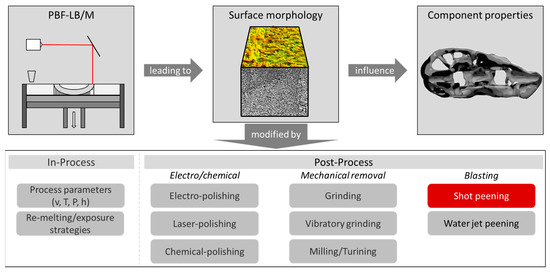
Figure 1.
Possible methods for modification of the PBF-LB/M surface and subsurface regions to increase the component performance according to Reference [27] (process parameters: scan velocity v, layer thickness T, laser power P and hatch distance h).
In this context, a subtractive manufacturing of the “as-built” surface and subsurface regions, and thus a removal of the notch effects and residual stresses, is commonly applied, leading in most cases to significantly increased fatigue strength. However, for topology-optimised components made by PBF-LB/M, which are complex and often have filigree geometries, the possibilities of machining to improve the surface quality are limited or even impossible.
For this kind of components, shot peening can be applied, which has been employed frequently in industry to improve the fatigue strength of conventionally manufactured components. During shot peening the highly concentrated contact of the peening beads with the additively manufactured “as-built” surface causes changes at the surface and subsurface region, not only a reduction of the surface roughness, but also the introduction of compressive residual stresses and a hardness increase [7,8,13,28,29]. These changes finally lead to an improved fatigue life of shot peened components [7,8,13,29,30]. Thus, shot peening has been used to extend the lifetime of components, e.g., in aerospace, automotive, and medical industries [31,32].
Shot peening involves several parameters that must be controlled to realise defined surface topographies and material properties in the subsurface region. The commonly used measure to characterise the overall influence of the parameters in shot peening is the Almen intensity, which inter alia depends on the peening material, the size of the peening beads, the distance between the nozzle and the part, the velocity of the peening material, the peening pressure and the time of shot peening [7,13,14,33].
As mentioned above, both, high surface roughness and pores, cause notch effects, leading to stress concentrations during load and thus reduce the component’s fatigue strength [34,35,36]. Consequently, the sensitivity of the material against these stress concentrations is crucial for the mechanical strength of additively manufactured materials [37,38]. As demonstrated in [37,38] this sensitivity can be evaluated using cyclic indentation tests (CITs), which enable the characterisation of the cyclic deformation behaviour. This allows to quantify the cyclic hardening potential, correlating with the ability to counteract stress concentrations [39,40]. Note that the measurements obtained in the CITs depend on microstructural phenomena, e.g., dislocation density or grain size, and are more sensitive to microstructural changes than conventional hardness measurements [40]. Using small indentation forces in CITs, local cyclic properties, e.g., in the subsurface region [39], can be analysed. Thus, CITs are predestined to analyse the impact of shot peening on the surface and subsurface regions.
To contribute to the understanding of shot peening on the changes in surface topography and subsurface region of additively manufactured parts, the “as-built” surfaces of specimens made of 316L and AlSi10Mg were shot peened and analysed. For this, CITs were performed within the subsurface regions to determine the distribution of the hardness as well as the local changes in cyclic deformation behaviour. Moreover, the changes in surface topography were measured by confocal microscopy and the residual stress distribution within this region was determined by X-ray diffraction (XRD) measurements. To elaborate the effect of shot peening, different parameters of shot peening were applied, i.e., the peening material and pressure were changed, respectively. Additionally, the interaction of shot peening with changes in the PBF-LB/M process parameters, resulting in different “as-built” microstructures, was investigated. Therefore, the AlSi10Mg specimens were manufactured with two different parameter sets of PBF-LB/M process.
In summary, this work focuses on the effects of shot peening on selected morphological properties of additively manufactured materials, namely topography, microstructure and mechanical properties (hardness and cyclic deformation behaviour) in the subsurface region and the residual stresses as well as their interdependency with the manufacturing and shot-peening process parameters.
2. Materials and Methods
2.1. Materials: AlSi10Mg and 316L
The specimens were produced using two different PBF-LB/M systems. For AlSi10Mg specimens, a ProX DMP 320 device of 3D Systems (Rock Hill, SC, USA) equipped with a fibre laser (maximum power 500 W; wavelength of 1070 nm; laser beam diameter 65 µm) was used. The specimens made of austenitic stainless steel 316L were produced with an Mlab Cusing system from Conceptlaser (Lichtenfels, Germany), which is also equipped with a fibre laser (maximum power 100 W; wavelength 1064 nm; laser beam diameter 50 µm). For both processes, the building platform was not heated; the respective process parameters used are given in Table 1. Note that for the production of AlSi10Mg, the process was performed under argon atmosphere (O2 < 100 ppm), while the 316L specimens were manufactured in a nitrogen atmosphere (O2 < 0.7%).

Table 1.
Parameters used in PBF-LB/M and shot-peening processes and the respective definitions of the different conditions: nsp: non-shot peened; 3b/5b: shot peened with 3 bar and 5 bar, respectively; ss: stainless steel beads; c: ceramic beads; B1/B2: batch 1/batch 2).
As shown in Table 1, the AlSi10Mg specimens were manufactured with different parameter sets, which differ in laser power P and scan velocity v. These different PBF-LB/M parameter sets result in two different batches (B1 and B2), which are used to investigate the interrelation between the PBF-LB/M and the shot-peening process, as well as its influence on the changes at the surface and in the subsurface region.
For the presented investigations, cubic specimens with dimensions of 12 mm3 were manufactured. Overall, six specimens made of AlSi10Mg and five specimens made of 316L were produced. The respective specimens are named in accordance with Table 1.
2.2. Shot Peening Surface Treatment
Shot peening was applied with a SMG 100 D machine from MHG-Strahlanlagen (Düsseldorf, Germany). The specimens were shot peened in the “as-built” condition, while the four surfaces (each 12 mm × 12 mm) were oriented perpendicular to the build-up direction were post-treated. For the peening materials, ceramic (trade name: Zirblast) and stainless steel (trade name: CHRONITAL) were used, which were provided by VULKAN INOX GmbH (Hattingen, Germany). Both the ceramic and stainless steel beads had an average diameter of 600 µm. The parameters and peening materials used for shot peening are listed in Table 1.
2.3. Surface Topography Analysis
The investigations of the surface topography were conducted with a NanoFocus μsurf expert confocal microscope from NanoFocus AG (Oberhausen, Germany), which allows for a 3D analysis of the surface topography. For these investigations, a measuring field of 2.1 mm × 2.1 mm was applied, utilising a 20× magnification objective and a numerical aperture of 0.6. In accordance with ISO 25178-2, various roughness parameters, including the arithmetic average roughness (Sa) and the average maximum profile height (Sz), were determined to ensure accuracy and reliability. Note that for each specimen, four measuring fields were considered at the shot-peened or “as-built” surface, being the basis for the mean values of Sz and Sa.
2.4. Light Optical Microscope
To analyse the microstructure caused by PBF-LB/M and shot peening, light optical micrographs (LOMs) were taken from cross and longitudinal sections of the subsurface region of the non-shot-peened (nsp) and shot-peened specimens, respectively. For this, a Leica 6000 DM device (Wetzlar, Germany) was used. To visualise the grain structure, the cross and longitudinal sections were ground, polished and subsequently etched. Meanwhile, for the 316L specimens, V2A etchant was used, and the AlSi10Mg specimens were etched with 5% NaOH solution.
2.5. Cyclic Indentation Tests Including Microhardness Measurements
The changes in the mechanical properties of the subsurface region caused by shot peening were examined by cyclic indentation tests (CITs). The CITs were performed on a Fischerscope HM2000 (Sindelfingen, Germany) device equipped with a Vickers indenter. In the CITs, the material was loaded with a sinusoidal load function with a frequency of 1/12 Hz and a maximum force of 200 mN, while the indentation force F and the indentation depth h were continuously measured. From the second cycle on, F–h hysteresis loops were measured. Analogous to the plastic strain amplitude obtained from a stress–strain hysteresis, the half width of the F–h hysteresis at mean loading is defined as the plastic indentation depth amplitude ha,p, which serves as a measure for the plastic deformation in each cycle. Thus, the evolution of ha,p over the applied cycles (ha,p–N curve) enables a characterisation of the cyclic deformation behaviour and the cyclic plasticity. In a double-logarithmic plot, the ha,p–N curves show a stabilised slope after the fourth cycle, indicating a saturation of the macro-plastic deformation and a domination of microplasticity. Consequently, this regime of the ha,p–N curve can further be expressed by the power function ha,p II given in Equation (1).
Here, the exponent eII describes the slope of the ha,p–N curve in the stabilised regime. As a steeper slope represents a more pronounced cyclic hardening during cyclic indentation, eII is defined as cyclic hardening exponentCHT (CHT: Cyclic Hardening Test). Consequently, a higher absolute value of the exponent |eII| represents a material with a higher cyclic hardening potential, and thus, a bigger ability to counteract local stress concentrations. This approach of measuring and evaluating the F–h relation obtained in CITs is called PhyBaLCHT, which is described in more detail in previous work [39,41].
Note that besides the analyses of the cyclic deformation behaviour, the Martens hardness (HM) can be derived from CITs. Therefore, the F–h relation obtained in the first cycle can be used. Thus, information on the local monotonic properties is also provided by CITs.
For the investigation of changes in the mechanical properties of the subsurface region, CITs were conducted at surface distances of 50 µm, 100 µm, 200 µm, 300 µm, 500 µm and 1000 µm. At each surface distance, 40 CITs were performed, ensuring a high statistical reliability. Note that for this, the CITs were distributed over two polished cross-sections, being parallel to the building direction and perpendicular to two of the shot-peened side surfaces. To prevent interference between indentation points, the points were spaced at least five times the indenter diagonal. Moreover, a distance to the surface of three times the indenter diagonal was ensured to avoid edge effects. This resulted in a minimal surface distance of 50 µm of the indentations at both materials. This positioning of the indentation points is in accordance with DIN EN ISO 14577-1 [42].
The values of the mechanical measures, e.g., HM and |eII|, determined at different distances to the surface are presented in the following sections. In the respective diagrams, the measured data points are connected for a better visualisation using Bezier curves.
2.6. Residual Stress Analysis
To determine the residual stresses at the surface and in the subsurface region, X-ray diffraction (XRD) measurements were performed. The XRD data were recorded on a laboratory diffractometer X’Pert Pro from Malvern Panalytical (Malvern, United Kingdom). For the measurements, Cu-Kα1 radiation, an acceleration voltage of 40 kV and a beam current of 40 mA were used. The beam size and thus the measuring area had dimensions of 1.5 mm × 1.5 mm. Note that XRD measurements were performed at the “as-built” or shot-peened surfaces as well as at defined distances to these surfaces. For the latter, defined layers from the outer surface were removed electrolytically, enabling the analysis of the respective residual stress-depth profiles.
For the determination of the first-order residual stresses, the sin2ψ method was applied, using eight different angles of ψ from −69.30° to +69.30°. As diffraction peaks, the (2 2 0) plane of aluminium was used for AlSi10Mg and the (2 2 0) plane of austenite was used for 316L. The corresponding measurement parameters were 62.70° < 2θ (Al) < 67.70° and 72.92° < 2θ (Fe) < 76.48°, while a scanning speed of 0.005°/s was applied. For all specimens investigated, the residual stresses were evaluated in three directions with respect to the build-up direction, i.e., 0°, 45° and 90°, where 0° is parallel to the build-up direction. Analogous to the visualisation of the mechanical properties measured within the subsurface region, the values of the residual stresses measured at different surface distances are connected by Bezier curves in the respective diagrams.
3. Results
3.1. Analysis of the Surface Topography of 316L and AlSi10Mg Specimens
Figure 2 shows the surface topographies obtained for the 316L specimens with confocal microscopy. From these measurements of the surface topography, the corresponding quantitative values were derived, as shown in Table 2.
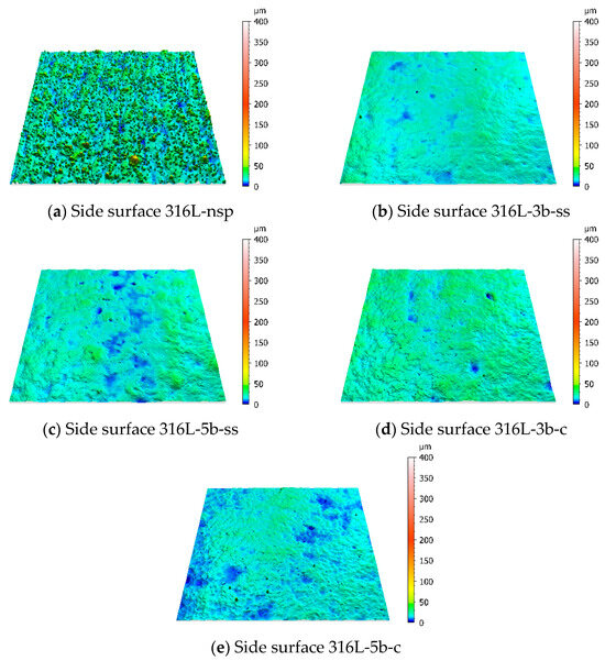
Figure 2.
Images of surface topographies (2.1 mm × 2.1 mm) obtained with confocal microscope at different conditions of 316L: (a) nsp: non-shot peened, (b,c) 3b/5b: shot peened with 3 bar or 5 bar and stainless steel beads (ss), (d,e) 3b/5b: shot peened with 3 bar or 5 bar and ceramic beads (c).

Table 2.
Sa and Sz obtained at the surfaces of 316L specimens.
The side surface of 316L-nsp (“as-built”, non-shot-peened), shows the highest average roughness Sa and maximum height Sz. All shot-peened surfaces show a reduction in surface roughness with respect to the as-built state. The corresponding images of surface topographies show a more uniform surface with fewer and less pronounced peaks. Increasing the pressure to 5 bar (316L-5b-ss) results in a slight increase in Sa compared to the 3b-ss specimen, while Sz decreases, suggesting a more pronounced compaction of the highest surface peaks. Similarly, the specimens treated with ceramic beads (316L-3b-c and 316L-5b-c) demonstrate a smoothed surface profile. The topographical maps of these specimens show an even finer structure compared to the surfaces treated with stainless steel beads.
Figure 3 shows the surface topographies obtained for the AlSi10Mg specimens, and the corresponding quantitative values are given in Table 3.
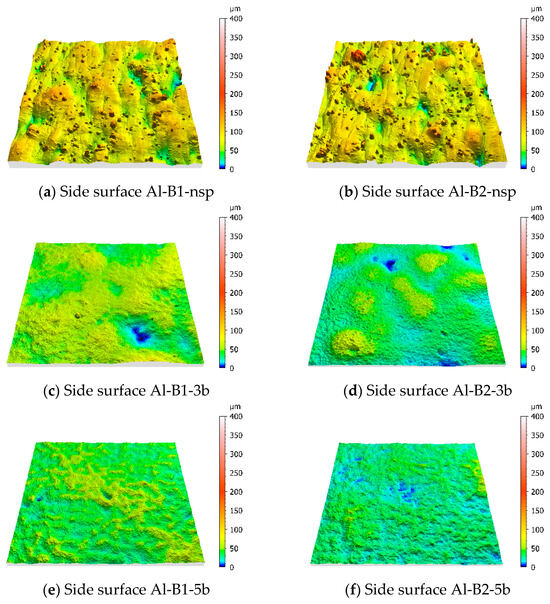
Figure 3.
Images of surface topographies (2.1 mm × 2.1 mm) obtained with confocal microscope at different conditions for AlSi10Mg. (a,b) nsp: non-shot peened, (c,d) 3b: shot peened with 3 bar, (e,f) 5b: shot peened with 5 bar.

Table 3.
Sa and Sz obtained at the surfaces of AlSi10Mg specimens.
The non-shot-peened AlSi10Mg specimens show higher surface roughness compared to the 316L-nsp specimen, represented by Sa and Sz, which corresponds to the bigger layer thickness (factor 3) used to produce the AlSi10Mg specimens (see Table 1). The roughness values obtained for AlSi10Mg specimens indicate a highly irregular surface, visible in the topographical images, which show pronounced peaks and valleys. Comparing the respective specimens of batch 1 (Al-B1-nsp) and batch 2 (Al-B2-nsp), the latter, manufactured with a reduced scan velocity of 1200 mm/s and a lower laser power of 272 W, shows a slightly lower Sa but a much higher Sz, indicating an influence of the manufacturing parameters on the surface topography.
When subjected to shot peening at 3 bar pressure, both Al-B1-3b and Al-B2-3b show a reduction in surface roughness. However, the reduction in surface roughness observed is differently pronounced for B1 and B2, which indicates an interrelation between the “as-built” roughness and the subsequent shot peening.
Further enhancements of Sa and Sz are observed for the 5 bar-pressure-treated specimens Al-B1-5b and Al-B2-5b. Both measures are in a similar range when comparing the two batches, and therefore, the differences of the initial conditions (nsp) for batch 1 and batch 2 are equalised by 5 bar shot peening.
As the number of surface measurements was limited, the statistical significance of the results must be considered with caution. However, the available data clearly show that the surface roughness decreases significantly after shot peening.
3.2. Microstructural Analysis of the Subsurface Region of Untreated and Shot-Peened Specimens
In Figure 4, light optical micrographs (LOMs) of the microstructure in the subsurface region of the different 316L specimens are shown. For each specimen, the melt pool boundaries and elongated grains, which extend these melt pool boundaries, are visible, being typical for additively manufactured 316L [19,37]. Comparing the non-shot-peened subsurface region (Figure 4a) with the subsurface region of specimens shot peened with stainless steel beads (Figure 4b,c), a plastically deformed zone is indicated by slip band formation and deformed grains. The latter aspect can be derived from the comparison of the grain structure shown for the non-shot-peened specimens with the grain structure of the shot-peened conditions. The plastically deformed zone described reveals a thickness of up to 15 µm, which slightly increases with higher peening intensity, i.e., an increase in pressure. In this zone, the melt pool and grain boundaries become less pronounced.
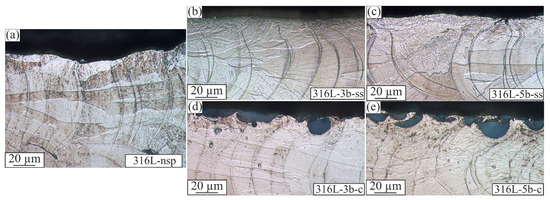
Figure 4.
LOMs of (a) non-shot-peened subsurface region of 316L specimens and the subsurface regions after shot peening with (b) low and (c) high pressure using stainless steel beads as well as with (d) low and (e) high pressure using ceramic beads.
The examination of the subsurface regions subjected to shot peening with ceramic beads reveals dark semicircular particles within the surface, identified as fragments of the ceramic peening beads. Analogous to the description above, plastically deformed zones can also be observed for the specimens shot peened with ceramic beads. More pronounced plastically deformed zones can be detected between and beneath the ceramic particles, reaching out up to a surface distance of 30 µm at higher peening intensities. Hence, based on the size of the plastically deformed zone, a stronger effect on the surface morphology (comprising the surface topography as well as the microstructure and properties of the subsurface region) of 316L can be seen when using ceramic beads. Moreover, the ceramic beads remain in the 316L specimens, which is different to the shot peening with stainless steel beads and influences the surface morphology. Since the ceramic beads have a minor plastic deformability and a higher stiffness, they do not plastically deform during the shot-peening process. Corresponding to the impact theory, the energy is only absorbed by the 316L specimen in the form of plastic deformation, while the ceramic beads do not plasticise at all. This leads to an embedding of the ceramic beads in the 316L specimens, which is present in nearly half of the shot-peened surface. In contrast, the stainless steel beads do also plastically deform; hence, the energy is absorbed by both the 316L specimens and the stainless steel beads, leading to a smaller plastically deformed zone in the subsurface region. Consequently, shot peening with the ceramic beads of 316L using the parameters utilised in this work leads to an undesirable surface quality, i.e., an embedding of the ceramic beads. However, the focus of this work is the analysis of different surface morphologies induced by shot peening. Since the shot peening with ceramic beads leads to pronounced plastically deformed zones, which indicate strong changes in the surface morphologies, it is of scientific interest to analyse the properties of the subsurface region in detail, which is shown in the following sections. In this context, it should be noted that the indentation tests and the residual stress measurements were performed in regions of sufficient distance to the ceramic beads, and hence, their effect on these measurements can be neglected.
Similar to the investigations on 316L specimens, microstructural analyses of the AlSi10Mg specimens were performed. The LOMs presented in Figure 5 show the microstructures of the surface regions obtained for non-shot-peened and shot-peened AlSi10Mg specimens from batch 2, which are also representative of the observations made for specimens of batch 1. In Figure 5a, melt pool boundaries as well as the contour area, having a depth of approximately 200 µm, can be observed for the non-shot-peened specimen. These microstructural features remain more or less unchanged after shot peening, and thus, the contour area is more extended than the region impacted by the shot peening. However, at higher magnification (Figure 5c,e), the shot-peened subsurface regions show crater-like microstructural changes in the bead impact zone, reaching up to 30 µm. In addition, material compression can be seen on the surface, represented as imprints of the shot-peening beads. These imprints indicate a substantial plastic deformation, and hence, the microstructural changes around them are expected to be plastically deformed zones, being more pronounced when using a higher pressure in shot peening. This is in correlation with the changes in topography presented in Figure 3 and Table 3.

Figure 5.
LOMs of (a) non-shot-peened surfaces and shot-peened surfaces of AlSi10Mg specimens of batch 2, while the surfaces resulting from shot peening are shown exemplarily in (b) (a higher magnification is given in (c)) for 3 bar and in (d) (a higher magnification is given in (e)) for 5 bar.
3.3. Change in Microhardness Due to Shot Peening
Due to the microstructural changes induced by shot peening, the respective change in the mechanical properties was analysed. For this, Figure 6 illustrates the microhardness distribution of the different 316L specimens in the subsurface region. This reveals an increase in hardness due to shot peening up to a surface distance of 200 µm, while the ceramic beads lead to a significantly higher hardness close to the surface. Note that the hardness measurements were performed beginning at a surface distance of 50 µm, and hence, at a sufficient distance from the embedded ceramic beads. Even at a lower shot peening pressure, a higher hardness is achieved than reached by stainless steel beads and a higher pressure of 5 bar. When comparing the effect of the different pressures, a hardness increase results from higher pressures when using ceramic beads, while roughly the same hardnesses are generated at both pressures with stainless steel beads.
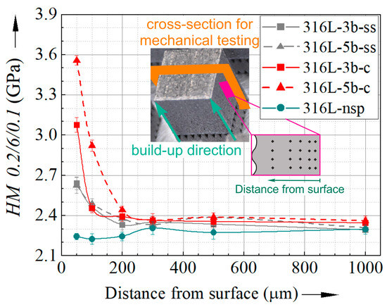
Figure 6.
Changes in microhardness along the distance to surface for non-shot peened and differently shot peened 316L specimens.
For AlSi10Mg specimens, the increase in hardness caused by shot peening is illustrated in Figure 7, showing for both batches a more pronounced hardness increase with higher shot peening pressures. This hardness increase is evident up to a surface distance of 200 µm compared to the non-shot-peened specimens. Note that the specimen of the batch B2 shot peened with 5 bar (Al-B2-5b) shows an increased hardness up to a surface distance of 300 µm, and thus, the most extended region of increased hardness. For the specimens shot peened with higher pressure, a continuous decrease in hardness with increasing surface distance is obvious, while the lower pressure leads to a stabilised hardness between 100 and 200 µm.
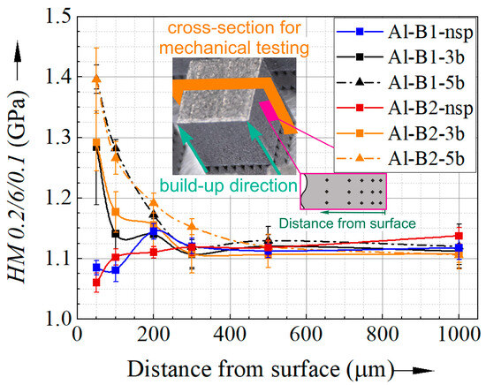
Figure 7.
Changes in microhardness along the distance to the surface for non-shot-peened and differently shot-peened AlSi10Mg specimens manufactured with different PBF-LB/M process parameters.
The maximum hardness achieved with shot peening does not depend on the AlSi10Mg batch used—since the two batches show a similar hardness at the near surface region—if the same shot peening parameters were used. Also, for the non-shot-peened conditions, no difference can be observed between the two batches investigated.
Nevertheless, the hardness of batch 2 tends to be influenced in a greater area due to the shot-peening process. Corresponding to this, the non-shot-peened condition of batch 1 shows a slightly increased hardness at a surface distance of 200 µm, which is less pronounced than at batch 2. Thus, the different manufacturing parameters seem to result in different microhardness distributions.
3.4. Change in Cyclic Deformation Behaviour Caused by Shot Peening
For a more detailed analysis of the mechanical properties in the subsurface region, the effect of shot peening on the cyclic deformation behaviour was analysed by means of the ha,p–N curves and the respective eII. Figure 8 shows the change in |eII| obtained from CITs for 316L specimens, revealing a reduction in |eII| in the subsurface region up to 100 µm, which was achieved with ceramic beads and 5 bar pressure. Using the lower pressure or stainless steel beads, a decrease in cyclic hardening potential is only achieved up to 50 µm. Thus, the decrease in |eII| correlates roughly with the increase in hardness shown in Figure 6. This is presumably caused by the substantial plastic deformation and the resulting increase in dislocation density, causing a strong work hardening effect. Consequently, in the hardened areas, the potential to form dislocations under additional loading is reduced, leading to a weaker cyclic hardening. Note that for the specimens shot peened with ceramic beads, these effects are observed at a sufficient distance from the embedded ceramic beads.
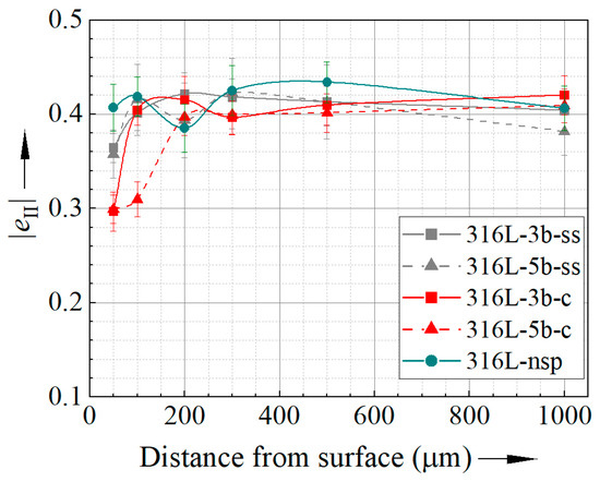
Figure 8.
Changes in |eII| determined in CITs performed at the investigated conditions of 316L specimens.
To analyse the cyclic deformation behaviour in the subsurface region of the 316L specimens, in Figure 9, the ha,p–N curves obtained at surface distances of 50 µm, 100 µm and 200 µm are illustrated.
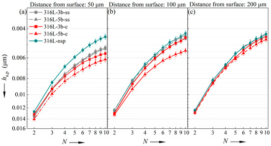
Figure 9.
ha,p–N curves obtained in CITs performed for 316L specimens at surface distances of (a) 50 µm, (b) 100 µm and (c) 200 µm.
At a distance of 50 µm, for the shot-peened specimens, an increase in ha,p is evident, which is more pronounced for the specimens shot peened with ceramic beads. While for shot peening with ceramic beads, the higher pressure lead to a higher increase of ha,p, for shot peening with the stainless steel beads, the impact of the pressure on ha,p is negligible. While for the other conditions, this increase in ha,p is only clearly visible at a surface distance of 50 µm, for the specimen shot peened with ceramic beads and 5 bar also at 100 µm, an increased ha,p is obtained. However, at 200 µm, for all conditions, no pronounced differences in ha,p–N curves are shown.
In accordance with Reference [43], the value of ha,p measured in the 10th cycle was considered to represent the extent of cyclic microplasticity for each surface distance investigated. Accordingly, Figure 10 illustrates the evolution of ha,p(10th cycle) along the surface distance, which corresponds to the qualitative analyses described above. Moreover, this evolution is similar to the hardness distribution shown in Figure 6. Hence, an increase in cyclic plasticity is accompanied with an increased hardness, which initially does not reveal any causal interaction. In this context, it was shown in previous work [43] that an increase in ha,p can be caused by compressive residual stresses, which is analysed in the following section.
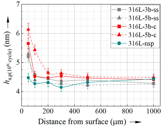
Figure 10.
Evolution of ha,p measured in the 10th cycle of CITs depending on the surface distance obtained for the different conditions of 316L specimens.
Analogous to the investigations performed for 316L specimens, Figure 11 illustrates the evolution of |eII| in the subsurface regions of the different AlSi10Mg specimens, revealing no substantial differences in cyclic hardening potential between subsurface regions and the inner material volume when considering the statistical deviation. Accordingly, no impact of the different shot-peening parameters is observed.
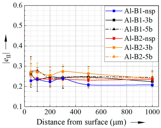
Figure 11.
Changes in the cyclic hardening exponent |eII| determined in CITs performed for the different conditions of AlSi10Mg specimens.
However, also for the AlSi10Mg specimens, the evolution of ha,p(10th cycle) along the distance to the surface was determined to analyse the influence of the shot peening on the cyclic deformation behaviour in detail, which is shown in Figure 12. For all shot-peened specimens, an increase in ha,p(10th cycle) from a surface distance of 50 µm to 200 µm is observed, while for all conditions, the maximum of ha,p(10th cycle) is reached at 200 µm. For higher pressures, slightly smaller ha,p(10th cycle) are achieved close to the surface, i.e., at 50 µm. Note that this region is also characterised by a high hardness depending on the pressure used, and thus, the lower cyclic plasticity indicated by ha,p(10th cycle) might be related to a pronounced hardness increase—shown in Figure 7—at this surface distance.
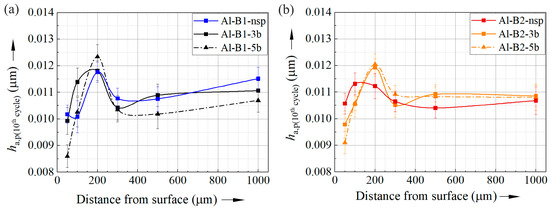
Figure 12.
Evolution of ha,p measured in the 10th cycle of CITs depending on surface distance obtained for the different conditions of AlSi10Mg specimens from (a) batch 1 and (b) batch 2.
Comparing the evolution of ha,p(10th cycle) obtained for the shot-peened specimens with the respective non-shot-peened specimens, at 50 µm, the shot-peened specimens show smaller ha,p(10th cycle). At a surface distance of 200 µm, an increased ha,p(10th cycle) is shown for the shot-peened specimens, except the specimens of batch 1 shot peened with 3 bar (Al-B1-3b). While the lower ha,p(10th cycle) at 50 µm correlates with a higher hardness, at 200 µm, the shot-peened specimens reveal a higher hardness and higher ha,p(10th cycle).
Analysing the non-shot-peened specimens, the evolution of ha,p(10th cycle) exhibits a maximum at 200 µm distance to the surface, which cannot be observed in the distributions of hardness or |eII|. Note that the area with the maximum ha,p(10th cycle) corresponds to the midpoint of the second melting path of the contour (see Figure 5), for which another set of process parameters was used instead for the inner material volume. Moreover, the evolutions of ha,p(10th cycle) along the surface distance are different between batch 1 and batch 2, and hence, ha,p(10th cycle) indicates microstructural changes within the subsurface region that cannot be detected by hardness or |eII|.
In summary, the findings obtained in the CITs indicate a negligible impact of shot peening on the cyclic properties of AlSi10Mg in the investigated material volume in relation to the changes observed for 316L specimens. Considering the more pronounced changes in hardness observed for the AlSi10Mg specimens, these results are surprising. However, as shown in Reference [43], the ha,p–N curves are influenced by residual stresses, which are assumed to be influenced by the shot peening and, thus, are analysed in the following.
3.5. Analysis of Residual Stresses in the Subsurface Region
Since shot peening is known to impact the residual stress state at and beneath the surface, the evolution of residual stresses within the subsurface region was investigated. To reduce the experimental effort, which is connected to such in-depth analyses, for each material, the XRD measurements were only performed for the non-shot-peened specimens (batch 2 for AlSi10Mg) and for the specimens that revealed the most pronounced changes due to shot peening, respectively. Moreover, the residual stresses were evaluated only up to a surface distance of 300 µm since, for greater distances, no pronounced changes in the mechanical properties due to shot peening were identified.
Figure 13 presents the residual stress profile of non-shot-peened 316L and the specimens shot peened with ceramic beads and 5 bar (316L-5b-c). Despite the embedded ceramic beads, the latter condition was chosen for the residual stress measurements since it showed the most pronounced changes in the subsurface region. However, as the ceramic beads would have an impact on the residual stress measurement at the surface, the outer surface layer and, hence, the ceramic beads were removed electrolytically in order to enable reliable residual stress measurements.
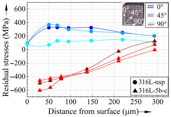
Figure 13.
Residual stress profile for non-shot-peened (lines with circles) and shot-peened 316L (lines with triangles), where the symbols represent the actual measurements and the lines show the interpolation of the experimental data.
The comparison shown in Figure 13 demonstrates a significant change in the residual stress state in the subsurface region caused by shot peening. While tensile residual stresses up to 380 MPa are present in the “as-built” state, compressive residual stresses up to −600 MPa are obtained after shot peening. The “as-built” state shows an increase in residual tensile stresses from the surface to a depth of 50 µm, followed by a more or less continuous decrease of the residual stresses. Note that the tensile stresses are less pronounced perpendicular to the build-up direction than in the other directions, representing an inhomogeneous residual stress state. Contrarily, residual compressive stresses are measured for the shot-peened specimen in the subsurface region, reaching distances from the surface from 35 µm to 200 µm. Thereby, a continuous decrease of the compressive residual stresses is observed with an increasing distance from the surface, leading to an approximately residual stress-free state at a distance of 300 µm. Note that in contrast to the “as-built” state, the shot-peened specimens show similar trends of the residual stresses between the three directions considered, and hence, the shot peening results in a more homogeneous distribution of the residual stresses.
For AlSi10Mg, Figure 14 shows exemplarily the residual stresses measured during the “as-built” state of batch 2 and the respective specimen shot peened with 5 bar. The “as-built” specimen of batch 2 shows residual tensile stresses directly at the surface, slightly increasing up to a distance from surface of 175 µm, which stays constant up to 300 µm. This corresponds to the residual stresses measured in the “as-built” 316L specimen. In correlation with the results obtained for 316L, parallel to the build-up direction, the residual stresses are higher than perpendicular to that, indicating an inhomogeneous distribution of the residual stresses. As expected and similar to the results obtained for 316L, the shot-peened AlSi10Mg specimen revealed residual compressive stresses, which show a maximum at a distance from the surface of 50 µm. Subsequently, the residual stresses get less pronounced but are not relieved until 280 µm, which is contrary to the results obtained for 316L. However, the evolution of the residual stresses along all three directions is nearly identical, which indicates that the shot peening leads to a homogeneous distribution of the residual stresses, being in line with the results shown for 316L.
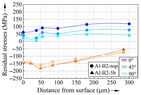
Figure 14.
Residual stress profile for non-shot-peened (lines with circles) and shot-peened (lines with triangles) AlSi10Mg of batch 2, where the symbols represent the actual measurements and the lines show the interpolation of the experimental data.
Comparing the different materials, the region of compressive residual stresses is more extended for the AlSi10Mg specimens than for 316L. This is mainly attributed to the differences in the strength between AlSi10Mg and 316L but is also influenced by the different materials used for shot peening, i.e., ceramic and stainless steel beads, which leads to different intensities. However, the shot-peened specimens of the different materials show qualitatively similar distributions of the residual stresses in the subsurface region. Considering the differences in residual stresses and mechanical properties induced by shot peening, for both materials, the residual stresses are changed in a bigger material volume than indicated by the change in mechanical properties.
4. Discussion
4.1. Effect of Shot Peening on the Surface Morphology of 316L
As expected, the various results obtained for the 316L specimens reveal a substantial influence of the shot peening on the surface morphology. Confocal and light optical microscopy show a strong plastic deformation due to shot peening. Generally, this plastic deformation seems to be more pronounced with increasing shot peening pressure. While the topographies achieved by shot peening with ceramic and stainless steel beads are similar, the light microscope images indicate a stronger plastic deformation due to the ceramic beads. The latter is assumed to be caused by the higher stiffness and hardness of the ceramic beads, which results in a nearly elastic deformation of the ceramic beads during shot peening, and hence, the kinetic energy is mainly absorbed by the specimen in the form of plastic deformation. This further leads to an embedding of the ceramic beads in the surface of the specimens to a depth of <20 µm. Note that the analyses of the properties of the subsurface region were performed at greater surface distances, and hence, the results are not influenced by this embedding effect. In turn, the stainless steel beads are assumed to also deform plastically, leading to a smaller proportion of absorbed energy in the specimens’ surface and subsurface region.
The plastically deformed zone beneath the surface is also visible in the microhardness distributions, showing an increased hardness near the surface and in the subsurface regions, respectively. In accordance with the increased hardness (see Figure 6) and the corresponding work hardening in the subsurface region, the cyclic hardening potential, represented by |eII|, is decreased in this zone (see Figure 8). These effects on the mechanical properties are more pronounced with increasing peening pressure, being in line with the microstructural investigations. Accordingly, shot peening with ceramic beads leads to higher hardnesses and lower |eII| than shot peening with stainless steel beads. However, using the steel beads, no influence of the peening pressure on the mechanical properties or extent of plastically deformed zone is observed. For shot peening with stainless steel beads, it is assumed that after reaching sufficient surface hardening, the stainless steel peening beads do not lead to further strong plastic deformation of the specimens. This might be explained by the increased surface hardness, potentially shifting the plastic deformation mainly to the non-hardened peening beads. Thus, the increase in pressure from 3 bar to 5 bar does not have a strong effect on the surface morphology of the specimens.
In contrast to the increase in hardness and decrease in cyclic hardening potential, the plastically deformed zone beneath the surface reveals a higher level of plastic deformation in cyclic indentation tests, indicated by higher values of ha,p. Considering the results presented in Reference [43], this increase in ha,p can be a result of compressive residual stresses, leading to higher levels of compressive stresses during indentation testing, and hence, in a more pronounced plastic deformation. This is in line with the residual stress measurements performed at the condition 316L-5b-c, which reveals strong compressive residual stresses in the subsurface region. To further analyse this relation of ha,p and the compressive residual stresses, in Figure 15, ha,p(10th cycle) and the residual stresses in build-up direction (in 0° direction) are plotted together over the distance to the surface. Note that the CITs were performed at cross-sections of the specimens, and thus, the residual stresses in a 90° direction are resolved after preparation (compare Figure 6 and Figure 13). Thus, the ha,p(10th cycle) values cannot be influenced by residual stresses measured in this direction, and moreover, for the residual stresses at a 45°, an influence of the preparation cannot be excluded. However, for the 0° direction, the residual stresses are not supposed to be severely affected by the preparation. Hence, only the residual stresses in this direction were considered for this correlation. In accordance with Reference [43], higher ha,p(10th cycle) correlate well with compressive residual stresses, supporting the assumption described above. Thus, the change in ha,p(10th cycle) can be used for an evaluation of the residual stress states induced by shot peening of 316L specimens.
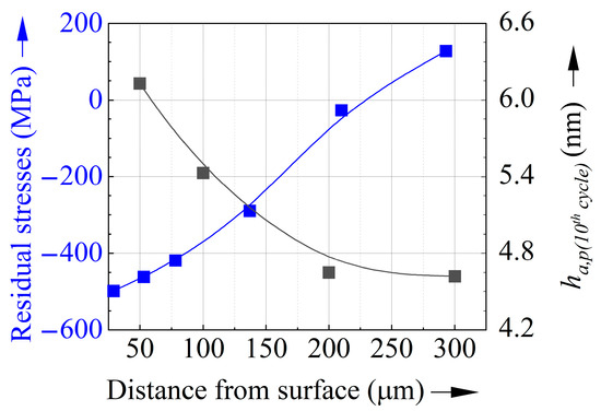
Figure 15.
Changes in residual stresses and cyclic plasticity observed in CITs (represented by ha,p obtained in the 10th cycle) in dependency with the distance from the surface for the 316L specimen shot peened with ceramic beads and a pressure of 5 bar (316L-5b-c). Note that the CITs were performed at the same distances from the surface, as shown in Figure 6.
4.2. Effect of Shot Peening on the Surface Morphology of AlSi10Mg
Similar to the results obtained for 316L specimens, the confocal microscope images and the microstructural analyses performed for the AlSi10Mg specimens reveal a strong plastic deformation due to shot peening, being more pronounced with increasing pressure in the shot-peening process. Accordingly, the subsurface regions of the AlSi10Mg specimens exhibit an increased hardness.
However, in contrast to the subsurface regions of 316L specimens, no decrease in cyclic hardening potential occurs in the plastically deformed zones of shot-peened AlSi10Mg specimens. Moreover, the AlSi10Mg specimens exhibit a decrease in cyclic plasticity (represented by ha,p(10th cycle)), which corresponds to the higher hardness, but is different than the observations made for the 316L specimens. Since the residual stress measurements show qualitatively similar results to those obtained for shot-peened 316L specimens, these different results cannot solely be explained with residual stresses.
In this context, it must be considered that the hardness increase caused by work hardening results in a decreased plastic deformability, while the compressive residual stresses induced by shot peening increase the level of cyclic plastic deformation in CITs (see discussion in Section 4.1). Consequently, these shot-peening-induced changes, i.e., the increased hardness and the compressive residual stresses, result in opposite effects on the cyclic plasticity occurring in CITs. Thus, the respective contribution of these single mechanisms and their individual extent must be considered. Since for 316L, the compressive residual stresses strongly correlate with the increase in ha,p(10th cycle), it is assumed for this material that the effect of residual stresses dominates the decrease in plasticity due to work hardening, while for AlSi10Mg, no clear correlation is observed. Thus, it is assumed that for the AlSi10Mg specimens, the effect on the increase in hardness dominates. This is in line with the results observed at a surface distance of 300 µm: At this distance, the hardness of the shot-peened specimen Al-B2-5b is nearly similar to the non-shot-peened specimen of batch 2. Thus, the effect of the increase in hardness on plasticity can be neglected, and, in correspondence to the assumption described above, a higher ha,p(10th cycle) is measured for the shot-peened specimen, correlating with compressive residual stresses. However, to prove this assumption and to elaborate on the relation between the different mechanisms, i.e., increased hardness, residual stresses and cyclic plasticity, further work is required.
Other than the effects of the shot peening itself, the results obtained for the AlSi10Mg specimens indicate an interrelation of the process parameters used in PBF-LB/M and shot peening. In addition to the differences in surface topography, the hardness measurements performed for the shot-peened specimens reveal slight differences between the specimens of batch 1 and batch 2. Since these differences are also partially present in the non-shot-peened conditions, it is assumed that they result from the respective additively manufactured surface roughness and microstructure, as well as their interaction with the peening beads. Consequently, the combination of the processes leads to different surface morphologies. To analyse this interrelation of the various process parameters, more variations in both processes must be investigated, being the objective of future work.
5. Conclusions
In this work, the effect of shot peening on the surface topography and the subsurface region, and hence, the surface morphology, of additively manufactured specimens made of 316L and AlSi10Mg was investigated. To manufacture the cubic specimens, a powder bed fusion laser beam metal (PBF-LB/M) process was used. To analyse the interrelation between the PBF-LB/M process and shot peening, two different parameter sets were used for the additive manufacturing of the AlSi10Mg specimens.
While the AlSi10Mg specimens were shot peened solely with stainless steel beads, the 316L specimens were treated with stainless steel beads and ceramic beads. Moreover, the pressure used in shot peening was varied (3 and 5 bar). To analyse the surface topography, confocal microscopy was used, while the microstructures of subsurface regions from non-shot-peened specimens and differently shot-peened specimens were investigated with light optical microscopy. Additionally, cyclic indentation tests were performed in the subsurface regions to determine the change in microhardness and cyclic deformation behaviour in dependency on the distance to the surface. This was accompanied by measurements of residual stresses in the subsurface region.
The following main conclusions can be drawn from the results obtained in the presented work:
- For both materials, a significant reduction in surface roughness was achieved by shot peening. The resulting surface roughness depended on the peening beads applied and the pressure used.
- The shot peening led to plastic deformation of the subsurface region, which extended up to 200 µm beneath the surface, while the depth of this area depended on the material treated and the shot peening parameters used. This plastically deformed subsurface region exhibited increased hardness and compressive residual stresses, being differently pronounced depending on the materials and shot peening parameters. Note that for 316L specimens, this zone also revealed a reduced cyclic hardening potential, while the AlSi10Mg specimens showed nearly no changes in cyclic hardening potential within this zone.
- While for AlSi10Mg, an increase in peening pressure led to a more pronounced plastically deformed subsurface region, for 316L, this occurred only for peening with ceramic beads. Using the stainless steel beads, an increase in pressure led to nearly no effect.
- For the AlSi10Mg specimens, an interrelation of the process parameters used in PBF-LB/M and the effects of the shot peening applied was observed.
- For 316L, a strong correlation between plastic deformation obtained in cyclic indentation tests and the compressive residual stresses induced by shot peening was observed. However, for AlSi10Mg, this correlation was only partially given, which might be caused by the differently pronounced effects of work hardening and residual stresses between the materials investigated. The evaluation of these differences is the objective of future work.
Author Contributions
Conceptualization, A.A.-Z., P.L., B.B. and M.S.; Methodology, A.A.-Z., P.L., B.B. and M.S.; Validation, A.A.-Z. and P.L.; Writing—original draft, A.A.-Z., P.L., B.B. and J.F.; Writing—review and editing, B.B., M.S., J.F., T.B. and R.T.; Visualization, A.A.-Z. and P.L.; Supervision, B.B., T.B. and R.T.; Project administration, B.B., T.B. and R.T.; Funding acquisition, T.B. and R.T. All authors have read and agreed to the published version of the manuscript.
Funding
The financial support by the priority research program of Rhineland-Palatinate “Advanced Materials Engineering (AME)” is gratefully acknowledged by the authors.
Data Availability Statement
Dataset available on request from the authors.
Acknowledgments
The authors thank the Institute of Measurement and Sensor Technology of Jörg Seewig for allowing access to the surface measurement equipment. We also thank Stefan Krzykowski from MHG Strahlanlagen GmbH for access to the shot peening machine.
Conflicts of Interest
The authors declare no conflicts of interest.
Abbreviations
The following abbreviations are used in this manuscript:
| AM | additive manufacturing |
| PBF-LB/M | powder bed fusion laser beam metal |
| CIT | cyclic indentation test |
| CHT | cyclic hardening test |
References
- F42 Committee. Terminology for Additive Manufacturing-General Principles-Terminology; ASTM International: West Conshohocken, PA, USA, 2022. [Google Scholar]
- Newton, R.; van Rensburg, J.; Scott, C.; Wohlers, T.; Campbell, R.I.; Diegel, O.; Huff, R.; Kowen, J. Wohlers Report 2023: 3D Printing and Additive Manufacturing: Global State of the Industry; ASTM International: West Conshohocken, PA, USA, 2023; ISBN 9781622049660. [Google Scholar]
- Majumdar, T.; Eisenstein, N.; Frith, J.E.; Cox, S.C.; Birbilis, N. Additive Manufacturing of Titanium Alloys for Orthopedic Applications: A Materials Science Viewpoint. Adv. Eng. Mater. 2018, 20, 1800172. [Google Scholar] [CrossRef]
- Jiménez, A.; Bidare, P.; Hassanin, H.; Tarlochan, F.; Dimov, S.; Essa, K. Powder-based laser hybrid additive manufacturing of metals: A review. Int. J. Adv. Manuf. Technol. 2021, 114, 63–96. [Google Scholar] [CrossRef]
- Kladovasilakis, N.; Charalampous, P.; Tsongas, K.; Kostavelis, I.; Tzovaras, D.; Tzetzis, D. Influence of Selective Laser Melting Additive Manufacturing Parameters in Inconel 718 Superalloy. Materials 2022, 15, 1362. [Google Scholar] [CrossRef]
- Yang, T.; Liu, T.; Liao, W.; Wei, H.; Zhang, C.; Chen, X.; Zhang, K. Effect of processing parameters on overhanging surface roughness during laser powder bed fusion of AlSi10Mg. J. Manuf. Process. 2021, 61, 440–453. [Google Scholar] [CrossRef]
- AlMangour, B.; Yang, J.-M. Improving the surface quality and mechanical properties by shot peening of 17-4 stainless steel fabricated by additive manufacturing. Mater. Des. 2016, 110, 914–924. [Google Scholar] [CrossRef]
- Bagherifard, S.; Beretta, N.; Monti, S.; Riccio, M.; Bandini, M.; Guagliano, M. On the fatigue strength enhancement of additive manufactured AlSi10Mg parts by mechanical and thermal post-processing. Mater. Des. 2018, 145, 28–41. [Google Scholar] [CrossRef]
- Damon, J.; Dietrich, S.; Vollert, F.; Gibmeier, J.; Schulze, V. Process dependent porosity and the influence of shot peening on porosity morphology regarding selective laser melted AlSi10Mg parts. Addit. Manuf. 2018, 20, 77–89. [Google Scholar] [CrossRef]
- Gundgire, T.; Jokiaho, T.; Santa-aho, S.; Rautio, T.; Järvenpää, A.; Vippola, M. Comparative study of additively manufactured and reference 316 L stainless steel samples–Effect of severe shot peening on microstructure and residual stresses. Mater. Charact. 2022, 191, 112162. [Google Scholar] [CrossRef]
- Maleki, E.; Bagherifard, S.; Bandini, M.; Guagliano, M. Surface post-treatments for metal additive manufacturing: Progress, challenges, and opportunities. Addit. Manuf. 2021, 37, 101619. [Google Scholar] [CrossRef]
- Maleki, E.; Bagherifard, S.; Unal, O.; Sabouri, F.; Bandini, M.; Guagliano, M. Effects of different mechanical and chemical surface post-treatments on mechanical and surface properties of as-built laser powder bed fusion AlSi10Mg. Surf. Coat. Technol. 2022, 439, 128391. [Google Scholar] [CrossRef]
- Maamoun, A.H.; Elbestawi, M.A.; Veldhuis, S.C. Influence of Shot Peening on AlSi10Mg Parts Fabricated by Additive Manufacturing. JMMP 2018, 2, 40. [Google Scholar] [CrossRef]
- Uzan, N.E.; Ramati, S.; Shneck, R.; Frage, N.; Yeheskel, O. On the effect of shot peening on fatigue resistance of AlSi10Mg specimens fabricated by additive manufacturing using selective laser melting (AM-SLM). Addit. Manuf. 2018, 21, 458–464. [Google Scholar] [CrossRef]
- Xie, B.; Xue, J.; Ren, X.; Wu, W.; Lin, Z. A Comparative Study of the CMT+P Process on 316L Stainless Steel Additive Manufacturing. Appl. Sci. 2020, 10, 3284. [Google Scholar] [CrossRef]
- Beretta, S.; Romano, S. A comparison of fatigue strength sensitivity to defects for materials manufactured by AM or traditional processes. Int. J. Fatigue 2017, 94, 178–191. [Google Scholar] [CrossRef]
- Yadollahi, A.; Shamsaei, N.; Thompson, S.M.; Elwany, A.; Bian, L. Effects of building orientation and heat treatment on fatigue behavior of selective laser melted 17-4 PH stainless steel. Int. J. Fatigue 2017, 94, 218–235. [Google Scholar] [CrossRef]
- Kan, W.H.; Nadot, Y.; Foley, M.; Ridosz, L.; Proust, G.; Cairney, J.M. Factors that affect the properties of additively-manufactured AlSi10Mg: Porosity versus microstructure. Addit. Manuf. 2019, 29, 100805. [Google Scholar] [CrossRef]
- Casati, R.; Lemke, J.; Vedani, M. Microstructure and Fracture Behavior of 316L Austenitic Stainless Steel Produced by Selective Laser Melting. J. Mater. Sci. Technol. 2016, 32, 738–744. [Google Scholar] [CrossRef]
- Bartlett, J.L.; Li, X. An overview of residual stresses in metal powder bed fusion. Addit. Manuf. 2019, 27, 131–149. [Google Scholar] [CrossRef]
- Riemer, A.; Leuders, S.; Thöne, M.; Richard, H.A.; Tröster, T.; Niendorf, T. On the fatigue crack growth behavior in 316L stainless steel manufactured by selective laser melting. Eng. Fract. Mech. 2014, 120, 15–25. [Google Scholar] [CrossRef]
- Leon Nope, G.V.d.; Perez-Andrade, L.I.; Corona-Castuera, J.; Espinosa-Arbelaez, D.G.; Muñoz-Saldaña, J.; Alvarado-Orozco, J.M. Study of volumetric energy density limitations on the IN718 mesostructure and microstructure in laser powder bed fusion process. J. Manuf. Process. 2021, 64, 1261–1272. [Google Scholar] [CrossRef]
- Gockel, J.; Sheridan, L.; Koerper, B.; Whip, B. The influence of additive manufacturing processing parameters on surface roughness and fatigue life. Int. J. Fatigue 2019, 124, 380–388. [Google Scholar] [CrossRef]
- Brenne, F.; Niendorf, T. Damage tolerant design by microstructural gradation–Influence of processing parameters and build orientation on crack growth within additively processed 316L. Mater. Sci. Eng. A 2019, 764, 138186. [Google Scholar] [CrossRef]
- Yu, W.; Sing, S.L.; Chua, C.K.; Tian, X. Influence of re-melting on surface roughness and porosity of AlSi10Mg parts fabricated by selective laser melting. J. Alloys Compd. 2019, 792, 574–581. [Google Scholar] [CrossRef]
- Boschetto, A.; Bottini, L.; Pilone, D. Effect of laser remelting on surface roughness and microstructure of AlSi10Mg selective laser melting manufactured parts. Int. J. Adv. Manuf. Technol. 2021, 113, 2739–2759. [Google Scholar] [CrossRef]
- Al-Zuhairi, A.; Ley, M.; Teutsch, R.; Schäfer, M.; Blinn, B.; Beck, T. Modifikation Von Oberflächenrauigkeit und Randschichthärte Additiv Gefertigter Strukturen Durch Nachbearbeitungsverfahren; Deutscher Verband für Materialforschung und -Prüfung e.V: Berlin, Germany, 2020. [Google Scholar] [CrossRef]
- Vinoth Jebaraj, A.; Sugavaneswaran, M. Influence of Shot Peening on Residual Stress Distribution and Corrosion Resistance of Additive Manufactured Stainless Steel AISI 316L. Trans. Indian Inst. Met. 2019, 72, 1651–1653. [Google Scholar] [CrossRef]
- Maleki, E.; Bagherifard, S.; Heydari Astaraee, A.; Sgarbazzini, S.; Bandini, M.; Guagliano, M. Application of gradient severe shot peening as a novel mechanical surface treatment on fatigue behavior of additively manufactured AlSi10Mg. Mater. Sci. Eng. A 2023, 881, 145397. [Google Scholar] [CrossRef]
- Hietala, M.; Rautio, T.; Jaskari, M.; Gundgire, T.; Järvenpää, A. The Effect of Laser Heat Treatment and Severe Shot Peening on Laser Powder Bed Fusion Manufactured AISI 316L Stainless Steel. MSF 2023, 1097, 17–23. [Google Scholar] [CrossRef]
- Badreddine, J.; Rouhaud, E.; Micoulaut, M.; Retraint, D.; Remy, S.; François, M.; Viot, P.; Doubre-Baboeuf, G.; Le Saunier, D.; Desfontaine, V. Simulation and experimental approach for shot velocity evaluation in ultrasonic shot peening. Mécanique Ind. 2011, 12, 223–229. [Google Scholar] [CrossRef]
- Qin, Z.; Li, B.; Zhang, H.; Youani Andre Wilfried, T.; Gao, T.; Xue, H. Effects of shot peening with different coverage on surface integrity and fatigue crack growth properties of 7B50-T7751 aluminum alloy. Eng. Fail. Anal. 2022, 133, 106010. [Google Scholar] [CrossRef]
- Zhang, H.; Cao, S.; Li, C.; Li, B.; Qian, G. Laser powder bed fused 304L steel shot peened with various ceramic shot sizes: Surface/subsurface characteristics, tensile behavior, and fatigue behavior. Int. J. Plast. 2023, 171, 103784. [Google Scholar] [CrossRef]
- DebRoy, T.; Wei, H.L.; Zuback, J.S.; Mukherjee, T.; Elmer, J.W.; Milewski, J.O.; Beese, A.M.; Wilson-Heid, A.; De, A.; Zhang, W. Additive manufacturing of metallic components–Process, structure and properties. Prog. Mater. Sci. 2018, 92, 112–224. [Google Scholar] [CrossRef]
- Murakami, Y.; Masuo, H.; Tanaka, Y.; Nakatani, M. Defect Analysis for Additively Manufactured Materials in Fatigue from the Viewpoint of Quality Control and Statistics of Extremes. Procedia Struct. Integr. 2019, 19, 113–122. [Google Scholar] [CrossRef]
- Romano, S.; Brückner-Foit, A.; Brandão, A.; Gumpinger, J.; Ghidini, T.; Beretta, S. Fatigue properties of AlSi10Mg obtained by additive manufacturing: Defect-based modelling and prediction of fatigue strength. Eng. Fract. Mech. 2018, 187, 165–189. [Google Scholar] [CrossRef]
- Blinn, B.; Krebs, F.; Ley, M.; Teutsch, R.; Beck, T. Determination of the influence of a stress-relief heat treatment and additively manufactured surface on the fatigue behavior of selectively laser melted AISI 316L by using efficient short-time procedures. Int. J. Fatigue 2020, 131, 105301. [Google Scholar] [CrossRef]
- Lehner, P.; Blinn, B.; Beck, T. Improving the Defect Tolerance and Fatigue Strength of AM AlSi10Mg. Adv. Eng. Mater. 2023, 25, 2201855. [Google Scholar] [CrossRef]
- Blinn, B.; Görzen, D.; Klein, M.; Eifler, D.; Beck, T. PhyBaLCHT–Influence of indentation force on the results of cyclic hardness tests and investigations of comparability to uniaxial fatigue loading. Int. J. Fatigue 2019, 119, 78–88. [Google Scholar] [CrossRef]
- Görzen, D.; Schwich, H.; Blinn, B.; Bleck, W.; Beck, T. Influence of different precipitation states of Cu on the quasi-static and cyclic deformation behavior of Cu alloyed steels with different carbon contents. Int. J. Fatigue 2020, 136, 105587. [Google Scholar] [CrossRef]
- Blinn, B.; Klein, M.; Gläßner, C.; Smaga, M.; Aurich, J.; Beck, T. An Investigation of the Microstructure and Fatigue Behavior of Additively Manufactured AISI 316L Stainless Steel with Regard to the Influence of Heat Treatment. Metals 2018, 8, 220. [Google Scholar] [CrossRef]
- DIN EN ISO 14577-1:2015-11; Metallische Werkstoffe_-Instrumentierte Eindringprüfung zur Bestimmung der Härte und anderer Werkstoffparameter_-Teil_1: Prüfverfahren (ISO_14577-1:2015). Deutsche Fassung EN_ISO_14577-1:2015; DIN Media GmbH: Berlin, Germany, 2015.
- Ostermayer, P.; Ankener, W.; Blinn, B.; Smaga, M.; Eifler, D.; Beck, T. Analysis of the Subsurface Volume of Differently Finished AISI 52100 by Cyclic Indentation and X-Ray Diffraction. Steel Res. Int. 2021, 92, 2100253. [Google Scholar] [CrossRef]
Disclaimer/Publisher’s Note: The statements, opinions and data contained in all publications are solely those of the individual author(s) and contributor(s) and not of MDPI and/or the editor(s). MDPI and/or the editor(s) disclaim responsibility for any injury to people or property resulting from any ideas, methods, instructions or products referred to in the content. |
© 2025 by the authors. Licensee MDPI, Basel, Switzerland. This article is an open access article distributed under the terms and conditions of the Creative Commons Attribution (CC BY) license (https://creativecommons.org/licenses/by/4.0/).