Article

Vacuum Brazing of 6061 Aluminum Using Al-Si-Ge Filler Metals with Different Si Contents

1
Department of Mechanical Engineering, Tsinghua University, Beijing 100084, China
2
State Key Laboratory of Advanced Brazing Filler Metals and Technology, Zhengzhou Research Institute of Mechanical Engineering, Zhengzhou 450052, China
*
Author to whom correspondence should be addressed.
Metals 2025, 15(8), 857; https://doi.org/10.3390/met15080857 (registering DOI)
Submission received: 8 February 2025 / Revised: 26 February 2025 / Accepted: 7 March 2025 / Published: 31 July 2025

Abstract

Al-xSi-35Ge (x = 4, 6, 8, 10, 12, wt.%) filler metals were prepared to vacuum braze 6061 aluminum alloy. The wettability of filler metals was studied. A thermodynamics model of the Al-Si-Ge ternary alloy was established to analyze the mechanism and impact of Si in the microstructure of the brazed joint. The findings indicated that Si addition had a slight effect on the melting point of Al-xSi-35Ge filler metals. Great molten temperature region of fillers was responsible for the loss of Ge during the wetting process, making residual filler metal difficult to melt. The microstructure of the joint was characterized by a multilayer structure that was primarily composed of three zones: two transition regions (Zone I) and a filler residual region (Zone II). There was liquidation of filler metal for Al-Si-35Ge filler metals during brazing, resulting in holes and cracks in joints. Increasing the Si content in fillers could alleviate the liquidation of filler metal, owing to diminishing difference of chemical potential of Ge (μGe) in fillers and 6061 substrates, hindering the diffusion of Ge from filler metal to substrates.

1. Introduction

The 6061 aluminum alloy was extensively used in fields such as electronic packaging, aerospace, and automotive manufacturing owing to its superior mechanical properties, formability, and corrosion resistance [1,2]. Currently, large-sized 6061 aluminum alloy components in high-end equipment were becoming increasingly complex in structure, causing higher requirements including joint strength, corrosion resistance, and weld forming quality. Welding techniques like laser welding and friction stir welding fall short in meeting the demands of joining 6061 aluminum alloy components with intricate structures [3,4]. This was especially true for thin-walled components, which were prone to developing substantial deformations during these processes [5]. Vacuum brazing, a clean, efficient, and high-quality welding technology, has unique advantages in achieving the connection of thin-walled and large components. It has been widely used in honeycomb panels, aerospace heat exchangers, and other fields [6,7,8,9].
Schwartz et al. connected 6061 aluminum alloy by vacuum brazing by using Al-Si brazing filler metal [10]. Zhang et al. and Tian et al. connected 6061 aluminum alloy by vacuum brazing by using Al-Si-Mg brazing filler metal around 580 °C [11,12]. However, the brazing temperatures of Al-Si and Al-Si-Mg filler metals were relatively high and close to the melting temperature of the 6061 alloy. Such a narrow brazing process window might induce substantial residual stresses, overall deformation, and even instances of overburning [13,14]. In recent years, in order to broaden the 6061 brazing process window, scholars have added elements such as Cu and Ge to Al-Si filler metal to reduce the melting point [15,16]. Al-Si-Cu filler metal could meet the brazing requirements, owing to its lower eutectic temperature (525 °C) [17]. However, there was an intermetallic compound such as CuAl2 and Cu4Al9 in the microstructure of Al-Cu-Si filler metal, resulting in reduced processability of the brazing filler metal. In addition, the large electrode potential difference between Cu and Al deteriorated the corrosion resistance of joints [18]. Ge had similar physical and chemical properties to Si, and the melting point of the Al-Ge alloy could reach 425 °C. Moreover, Ge could improve the spreadability of Al-Si alloy [19]. Thus, the study on Al-Si-Ge filler metal was one of the research hotspots in the vacuum brazing of 6061 aluminum alloy.
In recent years, research on Al-Si-Ge filler metal mainly focused on the lower melting point of fillers in order to reduce the brazing temperature. Werner et al. used amorphous Al-5Si-60Ge brazing filler metal for the vacuum brazing of 6061 aluminum alloy at 549 °C [20]. Kayamoto et al. prepared the brazing ribbons of Al-Si-Ge-Cu-Mg by rapid solidification technique and achieved vacuum brazing of 6061 aluminum alloy at 525 °C and 575 °C [21,22]. Fedorov et al. brazed 6082 aluminum alloy to 304 AISI using amorphous Al-40Ge-3.4Si brazing filler metals at 530 °C and 540 °C, respectively. Results showed that the microstructure in the joint was fine and homogeneous, but the shear strength of the joint was 20 MPa, which was lower than that of the induction brazing joint (53 MPa) [23]. Ivanikov et al. brazed 6082 aluminum alloy with amorphous Al-40Ge-3.4Si brazing filler metals at 520 °C and 540 °C, respectively, and the shear strength of the joint was 42 MPa [24].
In this paper, Al-xSi-35Ge (x = 4, 6, 8, 10, 12, wt.%) filler metals were designed to vacuum braze 6061 aluminum alloy. The melting characteristics and microstructure of filler metals were studied. The wettability of filler metals was analyzed. The influence of Si on microstructure in brazed joints was investigated.

2. Materials and Methods

The 6061 aluminum alloy (Al-0.8Si-1.2Mg, wt.%) rolling sheet produced by Mingtai Aluminum Industry (Zhengzhou, China) was employed as base metal. The base metal was cut into 10 mm × 10 mm × 10 mm blocks by wire electrical machining (DK7730). Before brazing, the surface of base metals was polished with 400 grit SiC sandpaper and then cleaned by ultrasonic.
High purity aluminum (99.99%, all compositions quoted in this work were in wt.% unless otherwise stated) and AlSi30 alloy produced by Mingtai Aluminum Industry (Zhengzhou, China) and germanium (99.999%) produced byYunnan Germanium Industry (Kunming, China) were used as raw materials to prepare Al-xSi-35Ge alloys (x = 4, 6, 8, 10, 12). All raw materials were melted in a clean graphite crucible by medium-frequency induction heating at 900 °C, holding for 5 min, and then the melt was poured into a cast graphite mold. The alloy ingots were cut into foils with a thickness of 0.2 mm by wire electrical machining.
The base metals and filler metals were assembled into a sandwich-type structure, as shown in Figure 1a. The vacuum degree of the vacuum brazing furnace (BK3-515) was controlled at less than 5 × 10⁻³ Pa. The brazing temperature was usually set to 30 °C higher than the liquidus of the filler metal. The brazing temperature in this work was set as 550 °C, and the holding time was 4 min. The detailed brazing process is shown in Figure 1c. The brazed 6061 joint was subjected to shear tests using a universal testing apparatus (DNS-100). The shear rate was 1 mm/min according to GB/T 11363-2008 [25], and the test was conducted using a self-designed fixture in Figure 1b. The average shear strength of three identical joints was calculated.
The brazed joints were sectioned perpendicular to the bonded interface and the microstructure of the braze zone, and the microstructure characteristics of the samples were analyzed by scanning electron microscopy (SEM, Sigma300, produced by Carl Zeiss AG in Oberkochen, Germany) equipped with an energy dispersive spectrometer (EDS, OXFORD Ultim MAX 40, produced by OXFORD Instruments in Oxford, UK). The phases observed in the microstructure were identified with an X-ray diffraction (XRD, Bruker D8, produced by Bruker in Karlsruhe, Germany). The melting points of these alloys were determined by differential thermal analysis (DTA, STA2500, STA2500, produced by METTLER TOLEDO in Zurich, Switzerland), which was heated from room temperature to 600 °C under a nitrogen atmosphere at a heating rate of 10 °C/min.

3. Results and Discussion

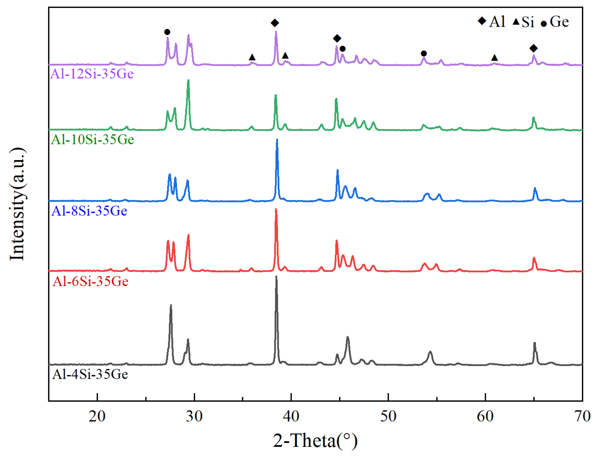
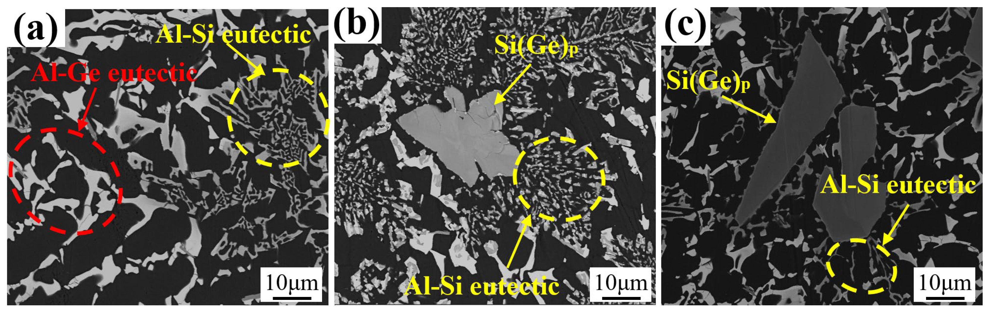
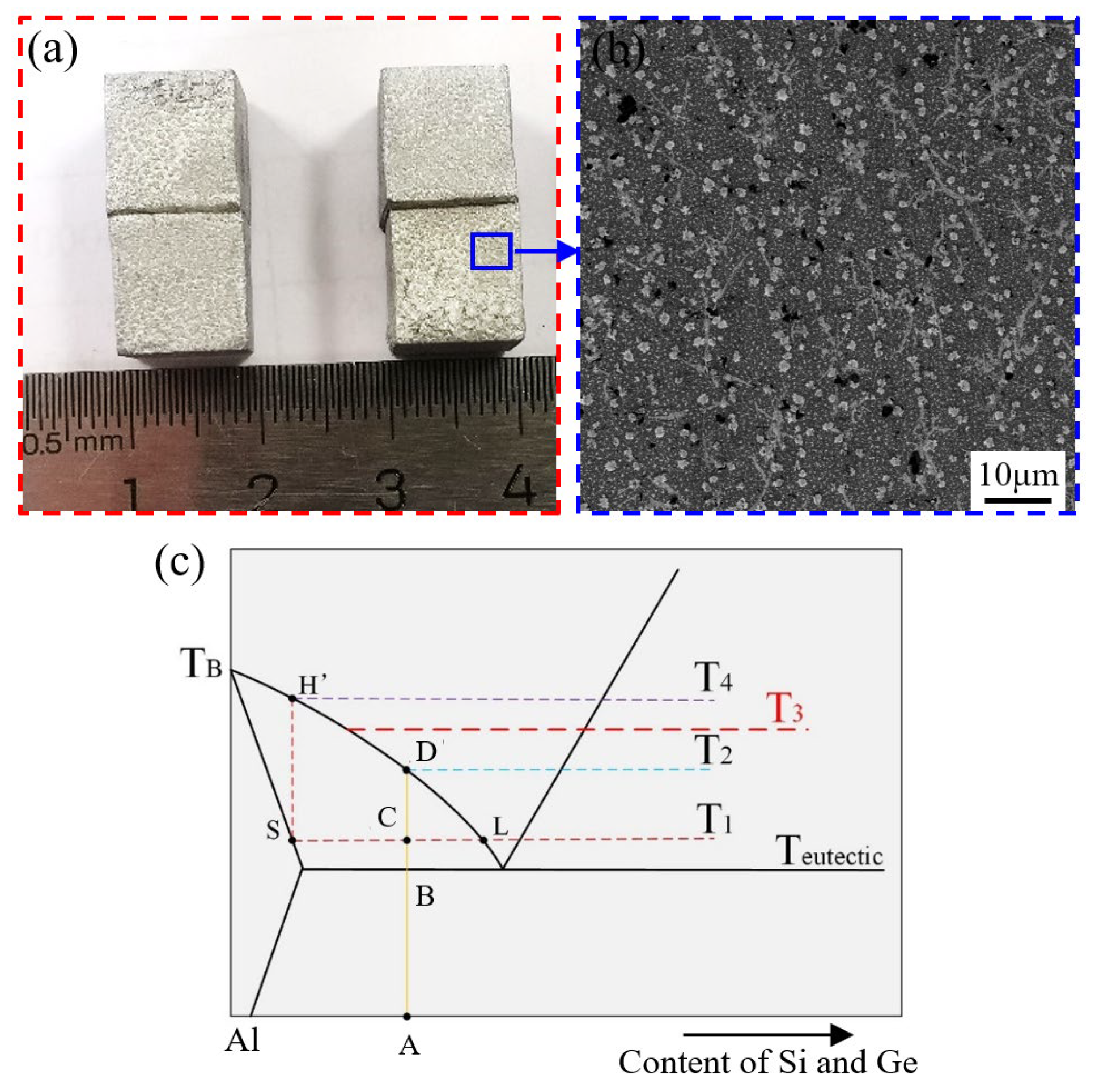
3.1. Microstructures of Al-Si-Ge Filler Metals

The microstructure and EDS analysis results of Al-6Si-35Ge filler metal are shown in Figure 2 and Table 1. It can be seen from Figure 2a that the white phase, gray phase, and black phase were observed in the microstructure of the filler metal. According to the EDS results as shown in Figure 2b–d, the black phase mostly included Al, and it was presented by phase A. The white phase and gray phase mainly included Si and Ge, which were presented by the phases of B, C, and D. It can be seen from Table 1 that the chemical composition of phase A was 0.62 wt.% Al + 1.31 wt.% Si + 98.7 wt.% Ge, the chemical composition of phase B was 97.96 wt.% Al + 2.04 wt.% Ge, and the chemical composition of phase C was 4.26 wt.% Al + 63.93 wt.% Si + 31.81 wt.% Ge. The XRD patterns of Al-xSi-35Ge filler metals are presented in Figure 3. All filler metals were composed of α-Al, Ge, and Si. Combining XRD and EDS analysis results, it can be confirmed that phase A, phase B, and phase C were α-Al, Ge-rich phase (Ge), and Si-rich phase (Si(Ge)), respectively. The chemical composition of lumpy phase D was similar to phase C, yet with higher Ge content and a bigger size. According to Ref. [13], phase C and phase D were primary Si(Ge) and eutectic Si(Ge). Figure 4 displays the microstructure of Al-xSi-35Ge filler metals. It could be seen from Figure 4 that there was no primary Si(Ge) in the microstructure of the Al-4Si-35Ge filler metal. When the Si content of the filler metal was 6 wt.%, primary Si(Ge) appeared. As Si content increased to 6 wt.%, the size of primary Si(Ge) increased. Therefore, Si promoted the formation of primary Si(Ge). Moreover, according to the Al-Si-Ge ternary alloy phase diagram [26], the Al-Si-Ge filler metal mostly consisted of the Al-Si eutectic phase and the Al-Ge eutectic phase, which were marked using a yellow circle and a red circle in Figure 4a. It can be seen that as the Si content increased, the Al-Si eutectic phase in the filler metal increased, and block-shaped Si(Ge) appeared in the filler metal. According to the research of Zhang et al. [13], the block-shaped Si phase was the primary Si(Ge) rather than the eutectic Si(Ge), and the block-shaped Si(Ge) increased when the Si content increased.

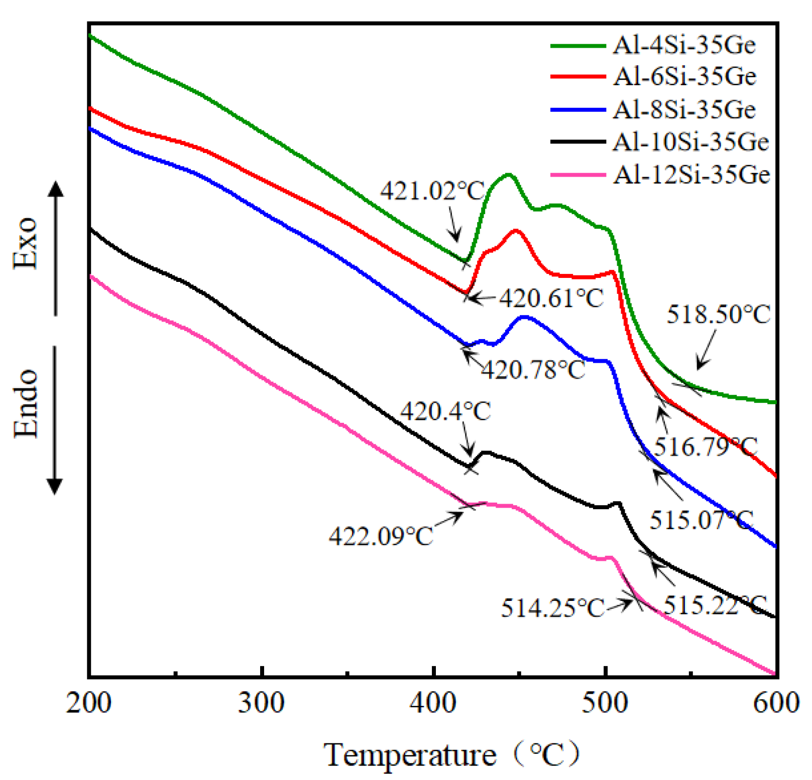
3.2. Melting Characteristics of Al-Si-Ge Filler Metals

Figure 5 shows the DTA curves of Al-xSi-35Ge filler metals with different Si contents. The solidus temperature (Tm) and liquids temperature (T1) could be obtained by calculating the inflection point around the endothermic peak in the DTA curves. The peak at 500–510 °C represented the Al-Si(Ge) eutectic reaction, and the peak at 420–430 °C represented the Al-Ge eutectic reaction. It can be seen that peaks in DTA curves tend to shift to the right with increasing Si content. According to Figure 5, Tm of filler metals did not show a regular change as the Si content increased, while the T1 of filler metals showed a decreasing trend. The maximum T1 of the filler metal was 518.09 °C when the Si content was 4 wt.%, and the T1 decreased to 514.25 °C when the Si content was up to 12 wt.%.

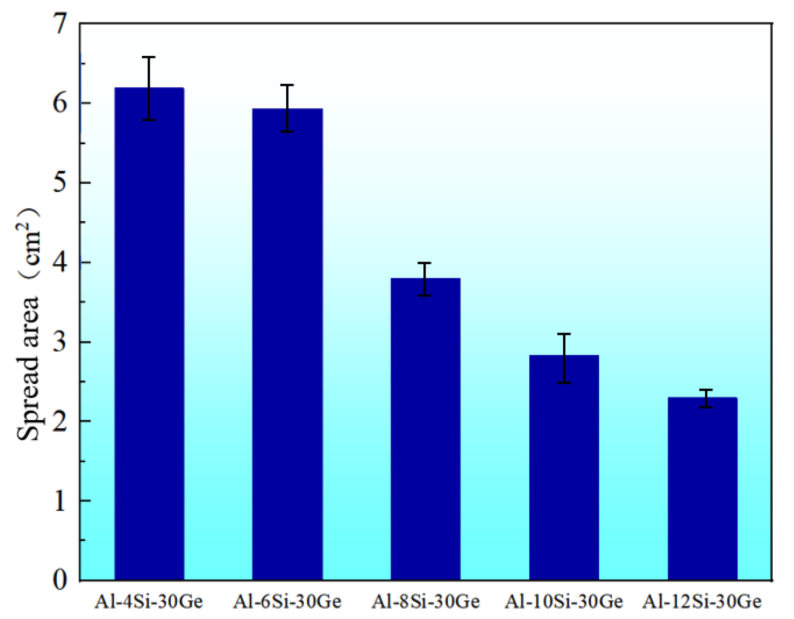
3.3. The Wettability of Al-Si-Ge Filler Metals

Figure 6 shows the wetting morphology and EDS analysis results of Al-8Si-35Ge filler metals on the surface of 6061 substrates at a temperature of 550 °C and a holding time of 4 min. It can be seen that although the wetting area of filler metals was relatively large, the spreading of the main filler metal was not ideal, forming an alloy tumor. Cheng et al. believed that this was due to severe loss of melting-point depressant element in filler metal, resulting in higher melting point of residual filler metal [27]. The microstructure and EDS analysis results of the wetting area of the Al-8Si-35Ge filler metal are shown in Figure 6b,c. It can be seen that the chemical composition of the wetting area were mainly Al and Ge, indicating that wetting of Al-Si-Ge filler metals was mainly related to Ge diffusion on the surface of base metal. Figure 6d,e displays the microstructure and major element distribution of Al-8Si-35Ge filler metal and residual filler metal. It can be seen that the characteristics of the Al-Si(Ge) eutectic structure disappeared in the microstructure of the residual filler metal, and the lumpy Si(Ge) phase increased. Moreover, Al-Ge eutectic reduced, and Ge content of filler metal reduced from 34 wt.% to 24.1 wt.%, which was consistent with analysis results from Figure 6b,c. The residual filler metal was harder to melt due to the loss of Ge. Figure 7 illustrates the spreading area of filler metals with different Si content on 6061 substrates. It can be seen that the spreading area decreased with the increasing Si content, suggesting that Si could prevent the spread of Al-Si-Ge filler metal and hinder the loss of Ge.

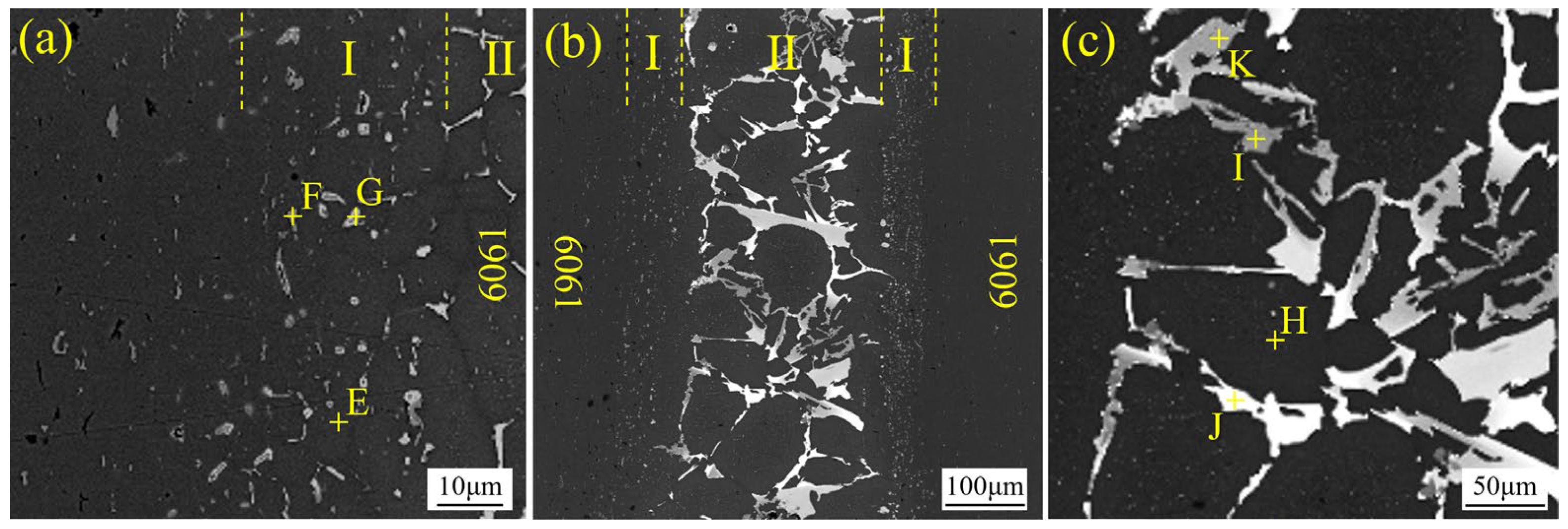
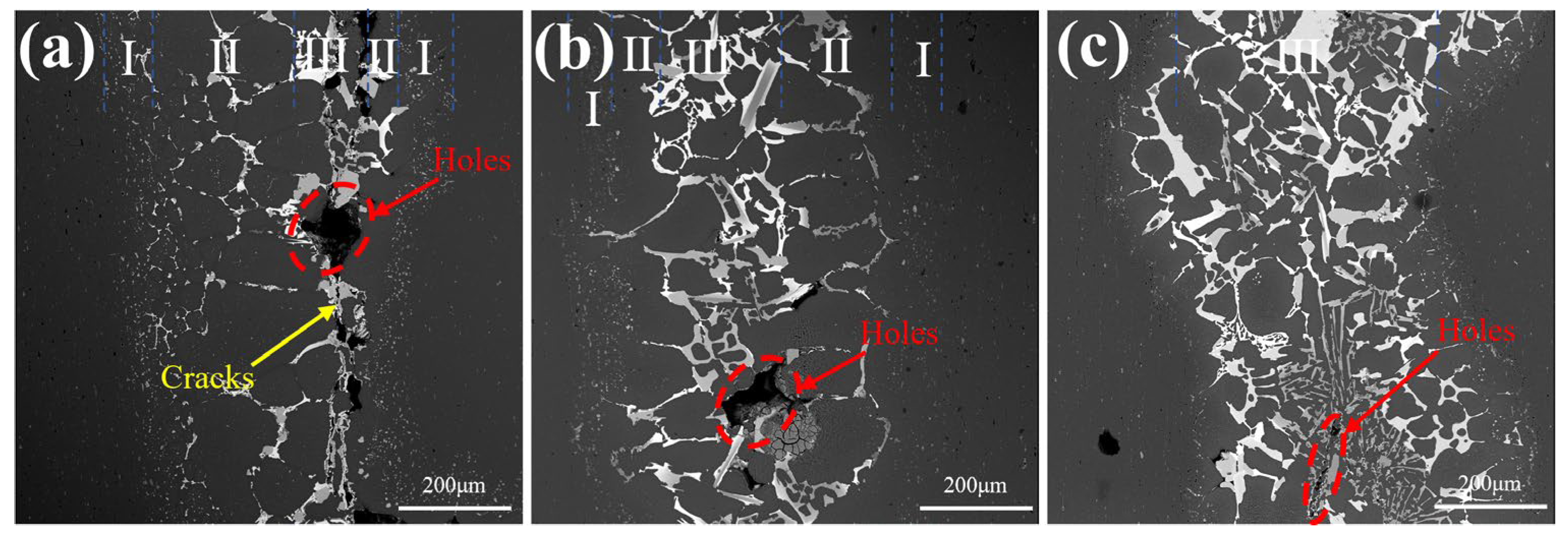
3.4. Microstructure of Vacuum-Brazed 6061 Joints

Figure 8a shows the macroscopic morphology of 6061 joints at a brazing temperature of 550 °C and a holding time of 4 min, and the microstructure of the surface of 6061 substrates is displayed in Figure 8b. It can be seen from Figure 8b that the morphology of the base material surface was similar to the wetting morphology. In addition, it can be seen in Figure 8a that there was unmelted residual filler metal outside the brazing seam, which was the typical characteristic of the liquidation of filler metal [28]. The mechanism of filler metal liquation is shown in Figure 8c. According to Ref. [28], liquidation of filler metal always occurred among the B–D segments in Figure 8c. When the filler metal composition was a (corresponding to the melting point T2), the brazing temperature was set to T3 to ensure the melting of filler metal during brazing. When the temperature rose to T1, the state of the brazing material was approximately composed of solid S and liquid L. According to the lever law, LC was the amount of solid phase, and CS was the amount of liquid phase. During the brazing process, the liquid phase flowed along the brazing seam, leaving only solid (S), which would not melt at the brazing temperature T3 and formed a filler metal overlap. Liquidation of filler metal was promoted by a large difference between solid–liquid phase lines (ΔT) of filler metals and a slow heating rate. According to Figure 5, the solid line of Al-Si-35Ge filler metal corresponding to the initial temperature of the extrapolated onset of Al-Ge eutectic was 420.4–422.09 °C, and the liquid line corresponding to the finishing temperature of the extrapolated onset of Al-Si(Ge) eutectic was 515.22–518.5 °C. The minimum ΔT can reach 92.16 °C. It could be seen from Figure 1c that the heating rate of vacuum brazing was 5–10 °C/min, so it needed at least 9 min to ensure the temperature increased from 421.02 °C (T eutectic) to 518.5 °C (T2). Therefore, both the great temperature difference and the long heating time cause the liquation of filler metals. The Al-Ge eutectic phase first melted and flowed along the surface of 6061, while the Al-Si(Ge) eutectic phase could not completely melt and formed filler metal overlap.
As illustrated in Figure 9, the microstructure of 6061 brazed structures with Al-8Si-35Ge was investigated when the brazing temperature was 550 °C. It can be seen from Figure 9b that the brazed joint consisted of two solid diffusion reaction layers (Zone I) and a filler metal residual zone (Zone II). Zones I was close to the 6061 alloy substrate and was composed of black phase, gray particle phase, and gray–white particle phase, which were represented by phases of E, F, and G in Figure 9a. Zone II was composed of black phase, gray block phase, gray–white block phase, and white phase, which were represented by phases H, I, J, and K in Figure 9c. It can be seen from the chemical composition in Table 2. The chemical composition of phase E was 97.4 wt.% Al + 1.7 wt.% Si + 0.9 wt.% Ge. Phase E was α-Al according to the Al-Si-Ge phase diagram. Phase F had brighter contrast when compared to the A phase. As indicated in Table 1, the chemical composition of phase F was 90 wt. % Al + 1.9 wt. % Si + 9.1 wt. % Ge. F phase was deduced to be Al-rich (Al, Ge) according to [15]. The contrast of the G phase was the lightest, compared to the phases of E and F. As indicated in Table 1, the chemical composition of phase G was 47.6 wt.% Al + 0.9 wt.% Si + 0.6 wt.% Si + 51.5 wt.% Ge. Phase G was deduced to be (Al, Ge) according to Ref. [23]. The chemical composition of phase H was close to phase E, and phase H was α-Al. The chemical composition of phase I was 1.2 wt.% Al + 59.2 wt.% Si + 39.6 wt.% Ge. Phase I was Si-rich Si(Ge) according to the Si-Ge phase diagram. As indicated in Table 1, the chemical composition of phase J was comparable to that of phase I, but Ge content at phase J was larger, being 55.6% (wt.%). Phase I was (Si, Ge). The chemical composition of phase K was 50.3 wt.% Al + 0.4 wt.% Si + 49.7 wt.% Ge. Phase K was (Al, Ge).
Figure 10 shows the microstructure of 6061 joints with Al-xSi-35Ge filler metals with different Si contents. The microstructure of joints with different filler metals was similar. Holes and cracks were found in the brazed joints, and it was reduced with the increasing Si addition. The causes of defects were closely related to the liquidation of filler metal. The Al-Ge eutectic phase began to melt at 420 °C, and the Al-Si eutectic phase completely melted above 514 °C. The Al-Ge eutectic with a low melting point melted and flowed along the surface of 6061 substrates, resulting in changes in the chemical composition of the residual filler metal. The melting point of residual filler metal increased, and it was difficult to melt at the predetermined brazing temperature due to the decreasing Ge content. The increase in melting point deteriorated the metallurgical bonding between residual filler metal and 6061 substrates and resulted in the formation of defects.

3.5. The Mechanism and Influence of Si in the Microstructure of Brazed Joint

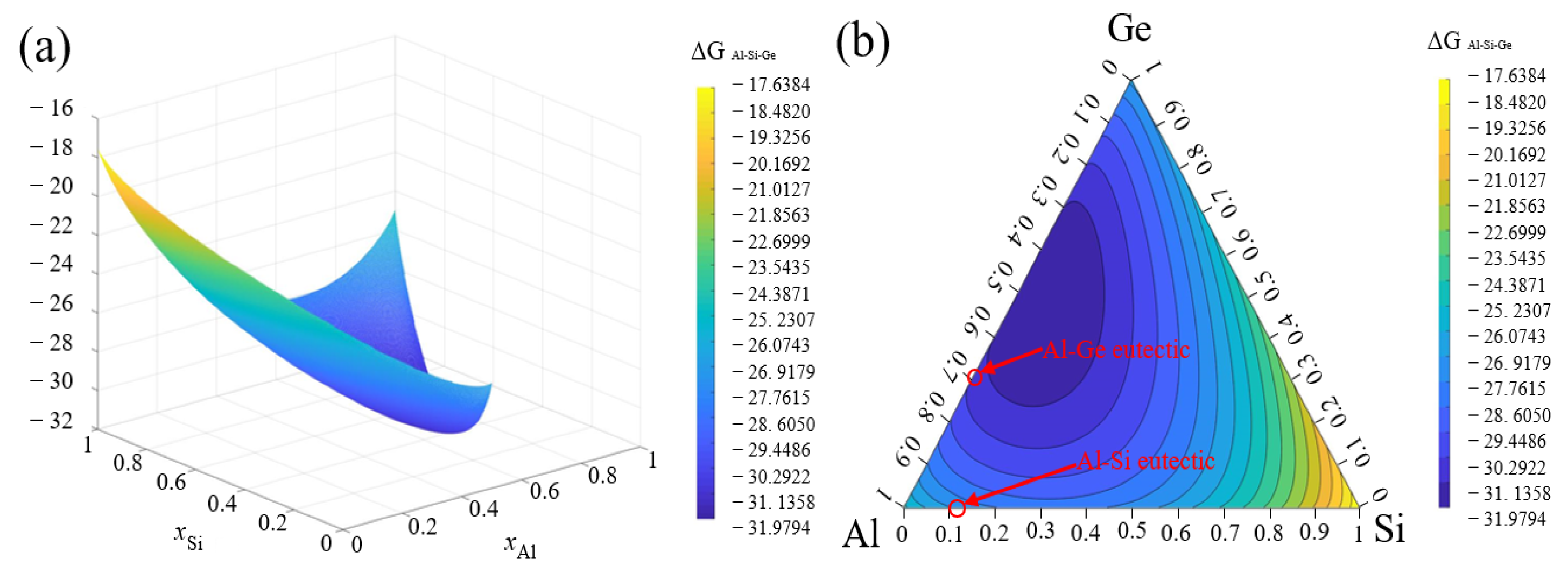
3.5.1. Thermodynamics Model

The metallurgical bonding between residual filler metal and 6061 substrates was realized through the diffusion of elements in the filler metals and substrates. According to the thermodynamic principle, element diffusion was dependent on the chemical potential. The chemical potential (namely, partial molar free energy) could be expressed by the following equation:
μ i = G x i
where µi is the chemical potential of element i, G represents the free energy of alloy systems, and xi represents the mole fraction of element i. G was always the summation of the excessive molar free energy GE and the ideal solution molar free energy GI.
Therefore, it could be expressed as follows:
G = G I + G E
GI could be expressed as follows:
G I = G 0 + G I = x i G i + x j G j + x k G k + R T ( x i ln x i + x j ln x j + x k ln x k )
where G 0 is the standard molar free energy; G I is the increment of G I resulted from atomic interaction; and Gi*, Gj*, and Gk* represent the molar free energies of pure components i, j, and k, respectively. x is the mole fraction of the corresponding component. R is the gas constant. T is the temperature.
GE is calculated with the Toop model [29]. GE could be calculated according to the values of GijE, GikE, and GjkE in the binary system, using the Toop model. GijE, GikE, and GjkE stand for the excessive molar free energy in i-j, i-k, and j-k binary systems, respectively.
G E = x j 1 x i G i j E x i , 1 x i + 1 x i x j 1 x i G i k E x i , 1 x i + G j k E ( x j 1 x i , 1 x i x j 1 x i )
G i j E could be expressed as follows:
G i j E = H i j T S m E
where ΔHij stands for the solution enthalpy (formation enthalpy) in the binary system and ΔSmE represents the excessive entropy in the binary system.
Tanaka et al. propose that the relationship between the excessive entropy ΔSmE and the solution enthalpy ΔHij could be described as follows [30]:
S m E = H i j ( 1 / T i + 1 / T j ) / 14
In this equation, Ti and Tj are the melting points of components i and j, respectively.
The excessive molar free energy of the binary system could be replaced by the following expression:
G i j E = H i j [ 1 T ( 1 / T i + 1 / T j ) / 14 ]
ΔHij could be calculated using the Miedema model of solution enthalpy, which is developed by Miedema et al. [31]:
H i j = f i j x i 1 + μ i x j i j x j 1 + μ j x i j i x i V i 2 / 3 1 + μ i x j i j + x j V j 2 / 3 1 + μ j x i j i
f i j = 2 p V i 2 / 3 V j 2 / 3 q / p n w s 1 / 3 2 2 b r / p n w s 1 / 3 i 1 + n w s 1 / 3 j 1
where x represents the molar fraction of elements. ϕ stands for electronegativity. V is the molar volume. nws represents the electron density. q, r, μ, a, p, and b are experimental constants. These parameters and values could refer to the research results reported by Miedema et al. [32,33].

3.5.2. Thermodynamics Analysis

Figure 11 shows the calculation results of the free energy of the Al-Si-Ge ternary system (GAl-Si-Ge) at 550 °C. It can be seen that GAl-Si-Ge was always negative, indicating spontaneous metallurgical reactions in the Al-Si-Ge ternary system. The position GAl-Si-Ge was on the Al-Ge side, indicating the existence of an Al-Ge eutectic phase in the alloy system. Figure 12 shows the calculated chemical potential of Ge (μGe) in the Al-Si-Ge ternary system at 550 °C. The μGe was −44.8 kJ/mol when the Al content was 98 wt.% (corresponding to the Al content of 6061). The μGe was higher than −10 kJ/mol when the Al content was 60 wt.% (corresponding to the Al content of Al-Si-Ge filler metals). Therefore, the driving force for Ge diffusion to regions with high Al content was higher, namely the trend of Ge diffusion from the filler metals to the 6061 substrates was higher. The reaction between the filler metal and 6061 substrates was achieved through the diffusion of Ge from the filler metals to the 6061 substrates, which was consistent with the EDS analysis results. The loss of Ge led to a decrease in residual solder activity and an increase in joint defects. According to the calculation results, the μGe in 6061 substrates was −24.5 kJ/mol. The μGe in Al-4Si-35Ge filler metal was greater than −1.5 kJ/mol, but it significantly decreased to −8.4 kJ/mol when the Si content was up to 12 wt.%. Obviously, Si addition could narrow the difference of μGe in the filler metals and 6061 substrates. The lower difference of μGe mean that weak trend of Ge diffusion from filler metals to 6061 substrates.
According to Section 3.3 and Section 3.4, the formation of brazing defects in the microstructure of joints resulted from the premature melting and flowing of the Al-Ge phase, which was related to the diffusion of Ge from filler metal to base metal. At this time, the larger the spread area was, the more severe the loss of melting-point depressant element Ge in the residual filler metals, resulting in the formation of defects in the brazed joints due to the increasing melting point of residual filler metal. According to the calculation results, Si addition can hinder the diffusion of Ge from filler metal to base metal, meaning that Si can reduce the loss of melting-point depressant element Ge in the residual filler metals. Hence, the spread area of filler metal was decreased, and defects in the brazed joint were reduced with increasing Si content in the filler metal, which was consistent with experimental results.

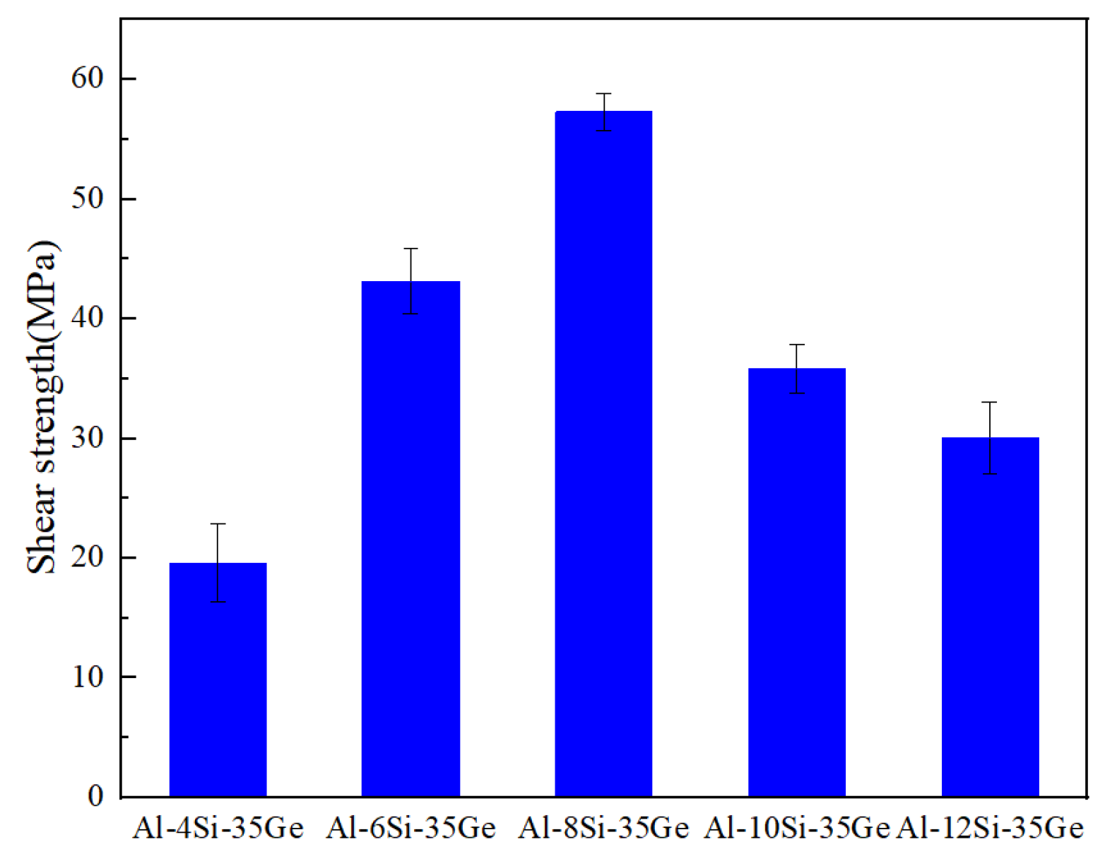
3.6. Mechanical Properties

The shear strength of 6061 joints is demonstrated in Figure 13. The shear strength with Al-4Si-35Ge filler metal was 19.6 MPa. When the Si content was up to 8 wt.%, the shear strength reached the maximum (57.3 MPa), but it decreased to 31.2 MPa with the further addition of Si. The fracture morphology of 6061 joints brazed with Al-Si-35Ge filler metals is shown in Figure 14. The chemical composition in the marked positions on the fracture surface is displayed in Table 3. The α-Al (positions 1, 4, 7), Ge (positions 2, 5, 8), and Si(Ge) (positions 3, 6, 9) were detected on the fracture surfaces. According to Figure 14a, there were a large number of cleavage steps and planes on Ge (position 2) and Si(Ge) (position 3) phases. The existence of the cleavage plane indicated cleavage fracture. However, no fracture characteristic on α-Al was observed, suggesting the existence of defects in the joint. Hence, the fracture mode of joints was “cleavage fracture + cleavage fracture”, and the joint shear strength was 19.6 MPa. It could be seen from Figure 14b that dimples on α-Al were observed (position 4) when using Al-8Si-35Ge filler metal. The existence of the dimples indicated ductile fracture. Similarly, cleavage steps and planes on Ge (position 5) and Si(Ge) (position 6) phases. Therefore, the fracture mode of joints was “ductile fracture + cleavage fracture”, and the shear strength was increased to 57.3 MPa. The fracture morphology of the joint with Al-12Si-35Ge filler metal is presented in Figure 14c. Ge (position 8) and Si(Ge) (positions 7, 9) were characterized by a lamellar cleavage plane, suggesting that the fracture mode of joints was “cleavage fracture “. It can be seen from Figure 10 that Si(Ge) and Ge in the brazed joints increased and coarsened when Ge content in filler metals rose from 4 wt.% to 12 wt.%. Moreover, the indentation hardness of Al, Ge, and Si(Ge) was 0.7 GPa, 10.2 GPa, and 11.5 GPa, respectively [24]. The coarse brittle phase reduces the toughness of the joint, leading to local stress concentration and cracking when the joint was subjected to shear force, thereby reducing the shear strength of the joint. Hence, the shear strength decreased to 31.2 MPa when Si content in the filler metals was 12 wt.%.

4. Conclusions

In the present work, five Al-xSi-35Ge (x = 4, 6, 8, 10, 12, wt.%) filler metals with different Si contents were prepared to braze 6061 alloy. The influence of Si content on the microstructure and melting characteristics of Al-xSi-35Ge filler metals was discussed. The influence of Si on the microstructure and shear strength of brazed joints was analyzed. The main conclusions were drawn as follows:
(1)
The melting point of Al-xSi-35Ge filler metals decreased from 518.5 °C to 515.22 °C when the Si content increased from 4 wt.% to 12 wt.%. The primary Si phase appeared in the microstructure of filler metals when the Si content was 6 wt.%.
(2)
The microstructure of the joint was characterized by a multilayer structure that was primarily composed of three zones: two transition regions (Zone I) and a filler residual region (Zone II).
(3)
Liquidation of filler metal occurred during brazing, resulting in the formation of defects such as holes and cracks in the microstructure of 6061 joints. Si can hinder this phenomenon by reducing the difference of μGe in fillers and 6061 substrates.
(4)
The maximum shear strength of the joint was 57.3 MPa, using Al-8Si-35Ge filler metal. Lower Si content in fillers resulted in defects in joints, and higher Si content introduced much more brittle Si(Ge).

Author Contributions

Conceptualization, S.H., J.Q. and J.S.; methodology, S.H.; software, C.J. and J.Q.; validation, S.H., Y.S. and C.J.; formal analysis, P.J.; investigation, S.H. and P.J.; resources, J.Q. and Y.S.; data curation, C.J.; writing—original draft preparation, S.H.; writing—review and editing, S.H.; visualization, J.Q. and C.J.; supervision, P.J.; project administration, Y.S. and C.J.; funding acquisition, S.H., J.Q. and J.S. All authors have read and agreed to the published version of the manuscript.

Funding

This research was funded by the National Natural Science Foundation of China, grant number U22A20191.

Institutional Review Board Statement

Not applicable.

Informed Consent Statement

Not applicable.

Data Availability Statement

The original contributions presented in the study are included in the article, further inquiries can be directed to the corresponding author.

Acknowledgments

The authors would like to thank everyone who provided help.

Conflicts of Interest

All authors declare that the research was conducted in the absence of any commercial or financial relationships that could be construed as potential conflicts of interest.

References

  1. Erturun, V.; Odabas, D.C. Fretting wear behaviour in 6061-T6 aluminium alloy. Aeronaut. J. 2024, 128, 178–190. [Google Scholar] [CrossRef]
  2. Zhu, Z.; Hu, Z.; Ng, F.L.; Seet, H.L.; Nai, S.M.L. Extending the mechanical property regime of laser powder bed fusion Sc- and Zr-modified Al6061 alloy by manipulating process parameters and heat treatment. Addit. Manuf. 2024, 85, 104164. [Google Scholar] [CrossRef]
  3. Zhang, D.; Wei, Z.; Wang, K.; Li, X. Brazing of Al2O3-6061 aluminum alloy based on femtosecond laser surface groove structure. Ceram. Int. 2022, 48, 36953–36960. [Google Scholar] [CrossRef]
  4. Xie, J.; Cai, C.; Zhang, B.; Yu, J.; Liu, Y.; Chen, H. Microstructure evolution and fracture behavior of rotating laser welded-brazed 6061 aluminum alloys/304 SS dissimilar joint. Mater. Charact. 2023, 195, 112543. [Google Scholar] [CrossRef]
  5. Li, Y.; Chen, C.; Yi, R.; Ouyang, Y. Special brazing and soldering. J. Manuf. Process. 2020, 60, 608–635. [Google Scholar] [CrossRef]
  6. Wang, J.; Li, D.; Liu, K.; Wang, Z.; Qing, G.; Wang, Y.; Yan, C.; He, C.; Zhang, R. Numerical and experimental investigation of an automatic brazing vacuum seal system for Mars soil sample return. Vacuum 2024, 219, 112687. [Google Scholar] [CrossRef]
  7. Li, Y.; Wang, J.; Ma, L.; Liu, Y.; Zhan, X. Thermal-fluid-solid coupling analysis of vacuum brazing process for a titanium alloy plate-fin structure. Vacuum 2023, 218, 112612. [Google Scholar] [CrossRef]
  8. Prakashraj, E.; Ghosh, A. Finite element based 3-D modelling of residual stress in high vacuum actively brazed diamond/Ni-Cr filler/C45 steel joint. Diam. Relat. Mater. 2023, 139, 110359. [Google Scholar] [CrossRef]
  9. Niu, Z.; Huang, J.; Yang, H.; Chen, S.; Zhao, X. Preparation and Properties of a Novel Al-Si-Ge-Zn Filler Metal for Brazing Aluminum. J. Mater. Eng. Perform. 2015, 24, 2327–2334. [Google Scholar] [CrossRef]
  10. Schwartz, M.; O’Keere, R. Fluxless Brazing of Aluminum. U.S. Patent 3457630A, 29 July 1969. [Google Scholar]
  11. Zhang, J.; Cheng, J.; Gong, Y. Welding 6061 airborne computer cabinet in high-precision vacuum brazing furnace. Vacuum 2009, 46, 6–8. [Google Scholar]
  12. Tian, H. Research on Domestic 6061 Vacuum Brazing and Gas Quenching Process. Mod. Weld. 2008, 4, 23–25. [Google Scholar]
  13. Zhang, Y.; Gao, T.; Liu, X. Influence of Ge content on the microstructure, phase formation and microhardness of hypereutectic Al-Si alloys. J. Alloys Compd. 2014, 585, 442–447. [Google Scholar] [CrossRef]
  14. Qiang, W.; Wang, K. Double-sided coaxial GTA flat-overhead welding of 5083 aluminum alloy. J. Mater. Process. Technol. 2019, 272, 9–16. [Google Scholar] [CrossRef]
  15. Chang, S.; Tsao, L.C.; Li, T.; Chuang, T. Joining 6061 aluminum alloy with Al-Si-Cu filler metals. J. Alloys Compd. 2009, 488, 174–180. [Google Scholar] [CrossRef]
  16. Niu, Z.; Huang, J.; Chen, S.; Zhao, X. Effect of germanium additions on the microstructures and properties of Al-Si filler metals for brazing aluminum. Trans. Nonferrous Met. Soc. China 2016, 26, 775–782. [Google Scholar] [CrossRef]
  17. Huang, T.; Gan, G.; Liu, C.; Ma, P.; Ma, Y.; Tang, Z.; Cheng, D.; Liu, X.; Tian, K. Properties of Cu/Zn+15%SAC0307+15%Cu/Al joints by different ultrasonic-assisted degrees. Microelectron. Int. 2023, 40, 70–80. [Google Scholar] [CrossRef]
  18. Long, W.; Lu, Q.; He, P.; Xue, S.; Wu, M.; Xue, P. In situ synthesis of Al-Si-Cu alloy during brazing process and mechanical property of brazing joint. J. Mater. Eng. 2016, 44, 17–23. [Google Scholar]
  19. Niu, Z.; Huang, J.; Liu, K.; Xu, F. Microstructure and property of 6061 aluminum alloy brazed joint with Al-Si-Ge-Zn filler metal. Trans. China Weld. Inst. 2017, 38, 97–101. [Google Scholar]
  20. Werner, W.; Tenn, C. Fluxless Aluminum Brazing. U.S. Patent 3844777A, 29 October 1974. [Google Scholar]
  21. Kayamoto, T.; Jong-Hoon, K.; Saito, S.; Onzawa, T. Brazing of Al-Mg alloy and Al-Mg-Si alloy with Al-Ge based filler metals. Q. J. Jpn. Weld. Soc. 1994, 12, 495–501. [Google Scholar] [CrossRef]
  22. Kayamoto, T.; Saito, S.; Ogusu, M.; Onzawa, T. Vacuum brazing of 2017 aluminum alloy using Al-Ge-Cu based fillers; Al-Ge-Cu ki ro wo mochiita 2017 aluminium gokin no shinku rozuke. Yosetsu Gakkai Ronbunshu 1995, 33, 20–24. [Google Scholar]
  23. Ivannikov, A.; Abramov, A.; Popov, N.; Penyaz, M.; Suchkov, A.; Pukhareva, N.; Sevryukov, O. Joining Stainless-Steel AISI 304 and High-Strength Aluminum Alloy AA 6082 by Brazing Using Al-Ge-Si Foils. Metals 2023, 13, 149. [Google Scholar] [CrossRef]
  24. Fedorov, V.; Uhlig, T.; Wagner, G. Microstructure and Mechanical Properties of AA 6082/AISI 304 Joints Brazed Using Al-Ge-Si Filler Metal. Metals 2023, 13, 1574. [Google Scholar] [CrossRef]
  25. GB/T 11363-2008; Test Method of the Strength for Brazed and Soldered Joint. General Administration of Quality Supervision, Inspection and Quarantine of the People’s Republic of China and China National Standardization Administration: Beijing, China, 2008.
  26. Zhang, Q.; Zhuang, H. Atlas of Ternary Alloy Phase Diagrams. In China Machine Press26; China Machine Press: Beijing, China, 2022; pp. 157–158. ISSN 978-7-122-40940-9. [Google Scholar]
  27. Cheng, Y.; Wu, X.; Zhou, Y.; Chen, Y. Study on brazability of Al–Cu–Si–Ni filler metal at medium-temperature on different parent metal. Electr. Weld. Mach. 2008, 38, 37–41. [Google Scholar]
  28. Zhang, Q.; Zhuang, H. Handbook of Brazing and Soldering, 3rd ed.; China Machine Press: Beijing, China, 2008; pp. 102–103. ISSN 978-7-111-57708-9. [Google Scholar]
  29. Liu, Z.; Li, Y.; Ruan, F.; Zhang, G.; Zhao, M.; Liu, Z.; Zhang, J. Enthalpy analysis of Ce–Mg–Ni–H formation based on extended miedema theory: Investigation of selected Ce2MgNi2–H2. Int. J. Hydrogen Energy 2021, 46, 4201–4210. [Google Scholar] [CrossRef]
  30. Witusiewicz, V.T. Thermodynamics of liquid binary alloys of the 3d transition metals with metalloids: Generalization. J. Alloys Compd. 1995, 221, 74–85. [Google Scholar] [CrossRef]
  31. Buschow, K.H.J.; Bouten, P.C.P.; Miedema, A.R. Hydrides formed from intermetallic compounds of two transition metals: A special class of ternary alloys. Rep. Prog. Phys. 1982, 45, 937–1039. [Google Scholar] [CrossRef]
  32. Mou, G.; Hua, X.; Wu, D.; Huang, Y.; Lin, W.; Xu, P. Microstructure and mechanical properties of cold metal transfer welding-brazing of titanium alloy (TC4) to stainless steel (304L) using V-shaped groove joints. J. Mater. Process. Technol. 2019, 266, 696–706. [Google Scholar] [CrossRef]
  33. Tan, C.; Zang, C.; Xia, H.; Zhao, X.; Zhang, K.; Meng, S.; Chen, B.; Song, X.; Li, L. Influence of Al additions in Zn–based filler metals on laser welding–brazing of Al/steel. J. Manuf. Process. 2018, 34, 251–263. [Google Scholar] [CrossRef]
Figure 1. (a) Assembly of the 6061 alloy joint; (b) brazing progress; and (c) assembly schematic of shear test.
Metals 15 00857 g001
Figure 2. The microstructure and EDS analysis results of Al-6Si-35Ge filler metal: (a) microstructure of filler metals; (b) the distribution of Al; (c) the distribution of Si; and (d) the distribution of Ge.
Metals 15 00857 g002
Figure 3. XRD patterns of Al-Si-35Ge filler metals.
Metals 15 00857 g003
Figure 4. Microstructure of Al-xSi-35Ge filler metals: (a) Al-4Si-35Ge; (b) Al-8Si-35Ge; and (c) Al-12Si-35Ge.
Metals 15 00857 g004
Figure 5. DTA curves of Al-xSi-35Ge filler metals.
Metals 15 00857 g005
Figure 6. The wetting of Al-8Si-35Ge filler metal on the surface of the 6061 alloy: (a) wetting morphology; (b) the distribution of major elements of the wetting boundary marked with red line in (a); (c) the distribution of major elements of the cross-section of the wetting boundary; (d) original filler metal; and (e) residual filler metal.
Metals 15 00857 g006
Figure 7. The spread area of different filler metals.
Metals 15 00857 g007
Figure 8. (a) Macroscopic morphology of the brazed joint; (b) microstructure of the 6061 surface; and (c) schematic diagram of the liquation of Al-Si-35Ge filler metals.
Metals 15 00857 g008
Figure 9. Typical microstructure of a 6061 joint brazed with Al-8Si-35Ge filler metal (a) and (c) magnified images of Zone I and Zone II in (b).
Metals 15 00857 g009
Figure 10. Interfacial microstructure of 6061 joints with Al-xSi-35Ge filler metals: (a) Al-4Si-35Ge; (b) Al-8Si-35Ge; and (c) Al-12Si-35Ge.
Metals 15 00857 g010
Figure 11. (a) Three-dimensional graphs and (b) corresponding contour maps for calculated free energy of Al-Si-Ge ternary system (ΔGAl-Si-Ge) at 550 °C.
Metals 15 00857 g011
Figure 12. (a) Three-dimensional graphs and (b) corresponding contour maps for calculated chemical potential of Ge (μGe) at 550 °C.
Metals 15 00857 g012
Figure 13. Shear strength of 6061 joints.
Metals 15 00857 g013
Figure 14. The fracture morphology of 6061 joints: (a) Al-4Si-35Ge; (b) Al-8Si-35Ge; and (c) Al-12Si-35Ge.
Metals 15 00857 g014
Table 1. EDS analysis results marked in Figure 2a (wt.%).
PointAlSiGePossible Phase
A97.9602.04α-Al
B0.621.3198.07Ge
C4.2663.9331.81Si(Ge)P
D054.2145.41Si(Ge)E
Table 2. EDS analysis results marked in Figure 9 (wt.%).
PointAlSiGePossible Phase
E97.41.70.9α-Al
F901.99.1(Al, Ge)
G46.10.653.3(Al, Ge)
H96.903.1α-Al
I1.259.239.6Si(Ge)
J5.243.950.9Si(Ge)
K50.30.449.7(Al, Ge)
Table 3. Chemical composition (wt.%) of the marked spots in Figure 14.
PointAlSiGeOPossible Phase
176.87.51.614.1α-Al
21.90.891.36Ge
30.352.546.11.1Si(Ge)
495.40.81.42.4α-Al
51.6097.11.3Ge
6056.142.31.6Si(Ge)
71.240.455.33.1Si(Ge)
82.80.793.82.5Ge
904850.11.9Si(Ge)
Disclaimer/Publisher’s Note: The statements, opinions and data contained in all publications are solely those of the individual author(s) and contributor(s) and not of MDPI and/or the editor(s). MDPI and/or the editor(s) disclaim responsibility for any injury to people or property resulting from any ideas, methods, instructions or products referred to in the content.

