Article

Influence of Microstructure and Heat Treatment on the Corrosion Resistance of Mg-1Zn Alloy Produced by Laser Powder Bed Fusion

by
Raúl Reyes-Riverol
1,2,
Ángel Triviño-Peláez
1,
Federico García-Galván
1,3,
Marcela Lieblich
1,
José Antonio Jiménez
1 and
Santiago Fajardo
1,*
1
National Centre for Metallurgical Research (CENIM-CSIC), Av. Gregorio del Amo 8, 28040 Madrid, Spain
2
Department of Materials Science and Engineering, Universidad Carlos III de Madrid, Av. Universidad 30, 28911 Leganés, Spain
3
Department of Mechanical, Chemical and Industrial Design Engineering, ETSIDI, Universidad Politécnica de Madrid (UPM), 28010 Madrid, Spain
*
Author to whom correspondence should be addressed.
Metals 2025, 15(8), 853; https://doi.org/10.3390/met15080853
Submission received: 11 July 2025 / Revised: 24 July 2025 / Accepted: 28 July 2025 / Published: 30 July 2025
(This article belongs to the Section Corrosion and Protection)

Abstract

The corrosion behavior of an additively manufactured Mg-1Zn alloy was investigated in both the transverse and longitudinal directions relative to the build direction, in the as-built condition and after annealing at 350 °C for 24 h under high vacuum. Microstructural characterization using XRD and SEM revealed the presence of magnesium oxide (MgO) and the absence of intermetallic second-phase particles. Optical microscopy (OM) images and Electron Backscatter Diffraction (EBSD) maps showed a highly complex grain morphology with anomalous, anisotropic shapes and a heterogeneous grain size distribution. The microstructure includes grains with a pronounced columnar morphology aligned along the build direction and is therefore characterized by a strong crystallographic texture. Electrochemical techniques, including PDP and EIS, along with gravimetric H2 collection, concluded that the transverse plane exhibited greater corrosion resistance compared to the longitudinal plane. Additionally, an increase in cathodic kinetics was observed when comparing as-built with heat-treated samples.

1. Introduction

Magnesium (Mg), with a density of approximately 1.74 g/cm3, emerges as a promising material in the transportation industry due to its lightweight nature and excellent strength-to-weight ratio. This not only addresses engineering challenges but also provides significant advantages in terms of energy efficiency and the reduction of CO2 emissions, the primary contributor to the greenhouse effect [1]. Moreover, exploring the versatile properties of magnesium extends its applicability to energy production and storage through electrochemical devices, such as advanced battery technologies. Mg-ion batteries have the potential to provide cost-effective solutions and readily available supply chain compared to traditional Li-ion batteries [2]. Furthermore, the possibilities offered by magnesium extend beyond these fields, reaching even into the realm of biomedicine, owing to its biocompatible nature and suitable mechanical properties that have garnered interest for applications in temporary implants [3].
Despite its appealing characteristics, it is well known that Mg alloys are highly susceptible to corrosion in aqueous environments. This arises from their low corrosion potential, ranging from approximately −1.3 to −1.6 V vs. Ag/AgCl [4], which results in anodic behavior against most structural metals. Furthermore, during anodic polarization, Mg alloys display a phenomenon known as anomalous hydrogen evolution (AHE), wherein the rates of the hydrogen evolution reaction (HER) increase with anodic polarization. This contradicts the expectations of conventional electrochemical kinetics and contributes to increased corrosion rates [5]. However, the mechanisms underlying AHE under anodic polarization remain unclear.
Moreover, Mg and its alloys typically exhibit low ductility, making it unsuitable for shaping and functioning as structural components. This limited ductility is attributed to the inherent challenges arising from the hexagonal-close-packed crystal structure (hcp), which offers fewer slip systems ascribed to a strong plastic anisotropy and an intrinsic brittleness in comparison to other metallic structures such as face-centered cubic (fcc) [6,7]. Consequently, most Mg alloy products are manufactured using casting methods, including pressure die casting. Applications of wrought magnesium alloys have been limited mainly due to challenges in formability and processability at room temperature [8].
To overcome the issues mentioned above related to the fabrication of low-ductility materials such as magnesium, additive manufacturing (AM) is considered as a promising alternative for producing tailored Mg components. In this respect, AM unveils a spectrum of distinctive advantages—design freedom, minimal waste generation, and energy efficiency—compared to traditional manufacturing methods [8,9]. A commonly employed technique in this technology is Laser Powder Bed Fusion (LPBF). This technique involves the deposition of a layer of metallic powder that is subsequently selectively melted by a high-power laser, then recoated with metallic powder and melted again, repeating the process layer by layer. This allows the construction of a three-dimensional piece according to the design previously created in a 3D computer model [10]. Within this context, it is relevant to note that the LPBF technique exhibits interesting characteristics, including an exceptionally high cooling rate, around 105 K/s [11]. This rapid solidification influences the microstructure of the material. As the cooling rate increases, grain refinement occurs, leading to a finer microstructure. Furthermore, rapid solidification affects the formation, size, and distribution of secondary phases. Generally, these phases are more electrochemically noble than the Mg matrix, forming local cathodic sites that promote micro-galvanic corrosion [12]. Consequently, variations in the amount and distribution of these phases directly influence the electrochemical behavior and corrosion resistance of the alloy [13,14]. In addition, higher cooling rates can enhance the solubility of alloying elements in the solid solution. Understanding and controlling these solidification parameters is essential for optimizing the corrosion performance of Mg alloys in practical applications [15]. Conversely, additive manufacturing processes inherently introduce residual stresses into fabricated components. The material experiences repeated and rapid local cycles of heating and cooling due to both the concentrated heat input and the swift movement of the heat source. This generates an exceptionally high temperature gradient, resulting in thermal stress [16]. While post-processing heat treatments are commonly applied to relieve these residual stresses [17], their influence goes beyond stress relief. In fact, from a corrosion perspective, the most significant impact of thermal treatments lies in their ability to modify the microstructure, specifically, grain size and the distribution of secondary phases [18,19]. Therefore, a comprehensive understanding of how heat treatments change the microstructure is essential to evaluating the corrosion resistance of LPBF-produced alloys.
In contrast to other structural metals such as titanium and aluminum alloys or stainless steels [20,21], a limited number of studies have been conducted using LPBF technology to investigate the microstructural properties of Mg alloys and their effect on the corrosion behavior. This may be attributed to the highly reactive nature of Mg powders under atmospheric conditions, which complicates handling due to safety concerns and requires careful control of oxidation during processing. Additionally, the narrow temperature range between the melting point (650 °C) and boiling point (1090 °C) of magnesium further complicates the processing. Moreover, optimized process parameters for these alloys are still lacking [9,22].
Among Mg alloys processed via additive manufacturing, WE43 has received considerable attention in the literature. For instance, Esmaily et al. [23] examined the microstructure and corrosion resistance of LPBF-processed WE43 and found that it exhibits a distinct microstructure, characterized by fine RE-rich oxides. This was associated with different corrosion behavior relative to the cast alloy, attributed to the significant redistribution of Zr and Y. In line with these observations, Zumdick et al. [24] compared WE43 processed by additive manufacturing and powder extrusion. The AM sample showed flake-like phases, likely from powder oxide shells, while the extruded one had smaller, spherical phases. The lower elongation in the AM sample was linked to phase morphology and higher porosity.
Similarly, other Mg alloys, such as those containing zinc, are also of interest due to their excellent mechanical properties and corrosion resistance. Shuai et al. [11] investigated the corrosion resistance of ZK60 Mg alloy for biodegradable implant applications obtained by selective laser melting (SLM). The enhanced corrosion resistance of the laser-melted ZK60 alloy was attributed to its refined grain, homogenized microstructure, and extended solid solution achieved through rapid solidification. In another study, Wei et al. [25] processed AZ91D alloy using SLM, showing that optimal laser energy inputs (83–167 J/mm3) are critical to avoid defects such as balling or evaporation. The resulting microstructure consisted of fine equiaxed α-Mg and β-Mg17Al12 phases. Compared to die-cast AZ91D, the SLM samples exhibited superior microhardness and tensile strength due to grain refinement and solid solution strengthening.
Nevertheless, despite such studies, a comprehensive understanding of the binary Mg-Zn system remains essential as a basis for the further development of more complex Mg-Zn-X alloys, which could potentially be used in the biomedical field, as zinc is a non-toxic element [26]. Among these, Mg-Zn-Ca alloys are a promising group for biomedical applications due to the non-toxic nature of zinc and its beneficial effects on biocompatibility and corrosion behavior [27]. In this context, Wei et al. [28] examined different Mg-xZn (x = 1, 2, 4, 6, 8, 10, 12 wt.%) binary alloys using LPBF. They explored the influence of Zn content on the cracking/densification behaviors, microstructure characteristics, and mechanical properties. It was found that the increase in the concentration of Zn notably hindered the densification response of the LPBF-processed alloys. In contrast, at a relatively low Zn content of 1 wt.%, the LPBF process allowed the production of nearly fully dense alloys. However, corrosion resistance of the different Mg-Zn alloys was not investigated in that study.
This paper investigates the influence of microstructure along the longitudinal and transverse planes on the corrosion resistance and anomalous hydrogen evolution behavior of a Mg-1Zn alloy fabricated by laser powder bed fusion (LPBF) in 0.1 M NaCl solution. Samples were analyzed both in the as-built condition and after annealing at 350 °C for 24 h under high vacuum, in order to induce significant microstructural modifications and evaluate their effect on electrochemical performance. Surface analysis, electrochemical techniques, and gravimetric hydrogen collection measurements were conducted on both orientations. Moreover, this study contributes to a broader understanding of the corrosion behavior of Mg-1Zn alloys by providing a basis for comparison with conventionally processed materials, as reported in recent literature.

2. Materials and Methods

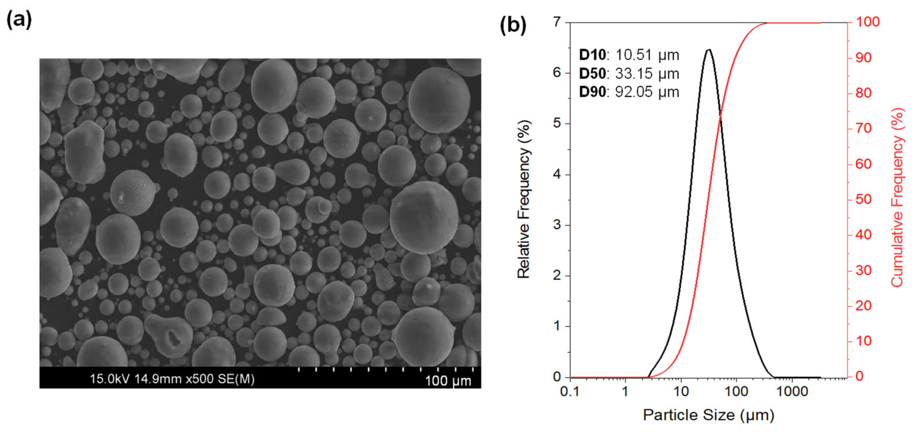
2.1. Starting Materials
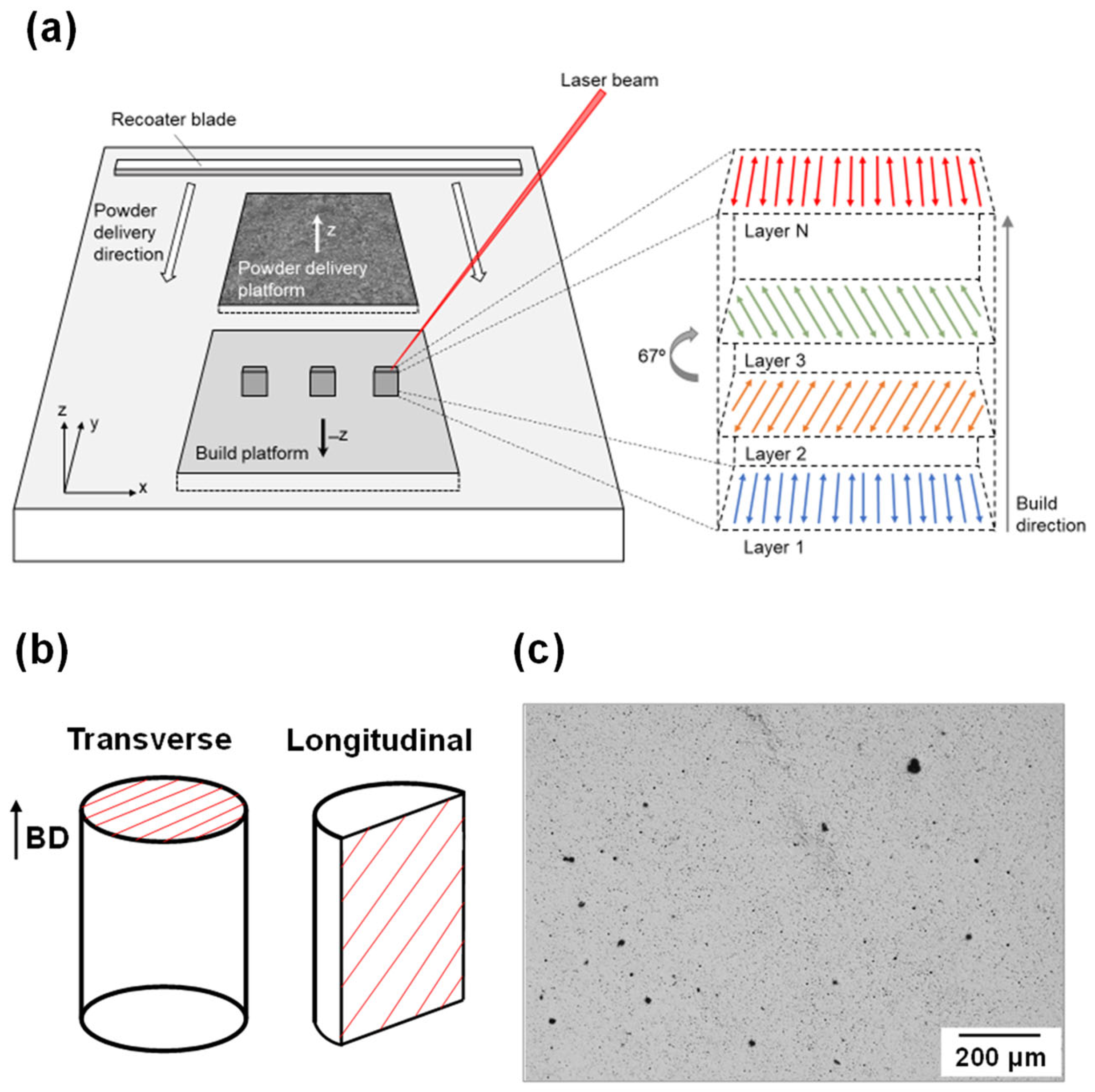
The Mg-1Zn alloy was produced by the laser powder bed fusion (LPBF) method from gas atomized Mg-1Zn powder delivered by Nitroparis (Nules, Spain). The chemical composition (in wt.%) of the Mg-1Zn powder can be found in Table 1. The particle size distribution of the powder was determined using a Malvern Panalytical Mastersizer 3000 laser diffraction particle size analyzer (Worcestershire, UK). The particle morphology was examined in more detail using scanning electron microscopy (SEM). As shown in Figure 1a, the powder is predominantly composed of spherical particles, although some exhibit surface irregularities and the presence of satellite particles. Figure 1b shows the particle size distribution curve, including the D10, D50, and D90 values corresponding to the respective percentiles.

2.2. Processing

A Renishaw AM 250 machine, equipped with a Reduced Build Volume (RBV) device, was employed to produce cylinders with a 7 mm diameter and 10 mm height under an argon atmosphere. Figure 2a illustrates a diagram exemplifying the operation process of the additive manufacturing machine. On the right side of Figure 2a, the laser orientation in each layer is depicted, varying at an angle of 67° for each layer. This approach ensures the maximum number of possible orientations before the same orientation is repeated [29,30].
Different conditions were explored for the preparation of the specimens by adjusting the laser power and scanning speed, while maintaining a fixed layer thickness of 50 µm and a hatch distance of 35 µm. Surface analysis after sample manufacturing, performed using ImageJ software (version 1.53k) on several randomly selected optical micrographs (Olympus BX41M-LED, Olympus Corporation, Tokyo, Japan) at 50× and 100× magnifications, revealed that the specimens produced at 100 W and a scan velocity of 325 mm/s exhibited the highest density. Under these conditions, the top part (Mg-1Zn Transverse) achieved a density of 97 ± 1%, while the lateral part (Mg-1Zn Longitudinal) exhibited a density of 96 ± 2%. Figure 2b provides a schematic representation of the printed specimens, showing the transverse and longitudinal planes, along with the build direction, while Figure 2c presents a representative optical micrograph of both sections of the as-built Mg-1Zn sample.
To evaluate the effect of heat treatment (HT) on the corrosion behavior of the LPBF produced samples, the cylinders were divided into two sets: one was annealed at 350 °C for 24 h in a resistance furnace under high vacuum (HT Mg-1Zn), while the other was left untreated (as-built Mg-1Zn). The annealing treatment at 350 °C is intended to relieve internal stresses generated during the additive manufacturing process and to promote partial microstructural homogenization and recrystallization. At this temperature, recrystallized grains can replace previously deformed regions, potentially eliminating deformation twins and leading to a more uniform and refined grain structure. These microstructural changes can significantly influence the corrosion behavior of the Mg-1Zn alloy, typically enhancing its corrosion resistance by reducing residual stress and minimizing solute segregation [31].

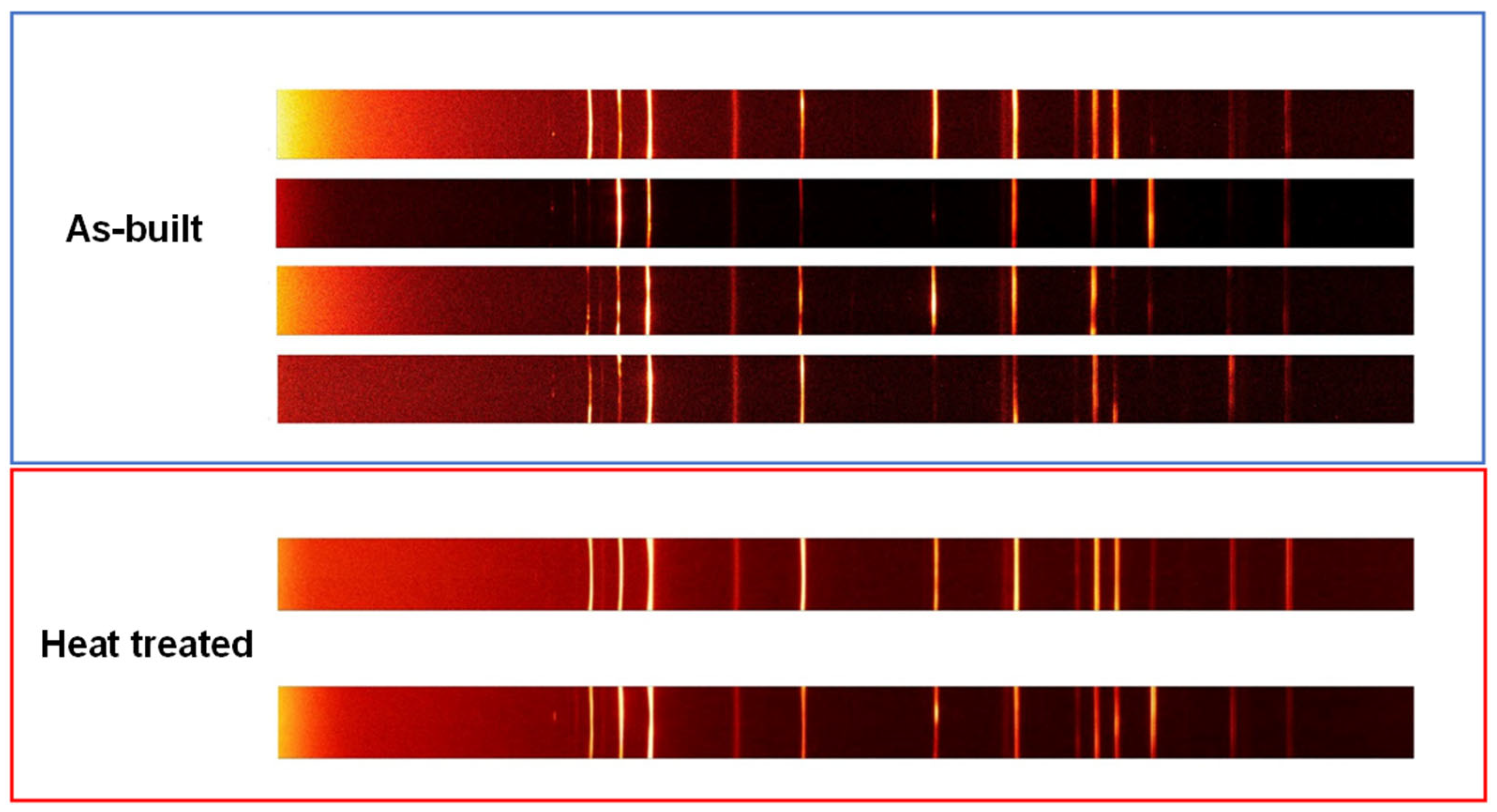
2.3. Microstructural Characterization

Samples for the microstructural characterization were prepared using a standard metallographic procedure. The specimens were cold-mounted in epoxy resin to prevent the heating associated with hot compression mounting using Bakelite, as it could affect the microstructure of the as-built Mg-1Zn sample. Subsequently, the specimens were ground using a series of SiC papers, and finally polished with diamond paste to a 1 μm finish. Ethanol was used as lubricant in all steps. The resulting surface was etched with an acetic–picral reagent (4.2 g picric acid, 5 mL acetic acid, 10 mL H2O, and 70 mL ethanol) to reveal the grain structure [32]. The microstructure of the printed specimens, both in the as-built condition and after annealing at 350 °C for 24 h under high vacuum, was examined using optical microscopy (OM) and a Hitachi S-4800 scanning electron microscope (SEM) equipped with an energy-dispersive X-ray spectroscopy (EDX) system from Oxford Instruments.
Electron backscatter diffraction (EBSD) crystal orientation maps were obtained by scanning the surfaces of samples that underwent an additional preparation step, consisting of a final polishing with a 0.06 μm water-free colloidal silica suspension (Etosil E). To prevent the formation of the native oxide films developed by Mg surfaces during preparation, a light etching was performed before the EBSD examination with a mixture of 7 mL acetic acid, 3 mL nitric acid, 30 mL ethanol, and 10 mL deionized water [33]. EBSD measurements were conducted using a JSM-6500F field emission scanning electron microscope (FEG-SEM) from JEOL Ltd. (Tokyo, Japan), equipped with a fully automated EBSD system from Oxford Instruments (HKL) (Oxfordshire, UK). EBSD mapping was carried out on an area of about 700 μm × 550 μm with a step size of 2 µm at an accelerating voltage of 15 kV. In the EBSD maps presented in this work, high-angle grain boundaries (HAGBs) were defined by a misorientation greater than 15°, while low-angle grain boundaries (LAGBs) were identified by a misorientation angle between 2° and 15°.
X-ray diffraction (XRD) measurements were conducted using a Bruker D8 Discover equipped with a cobalt anode (Kα λ = 1.78897 Å), a focusing Goebel mirror, and an Eiger2R 250K detector (Dectris USA Inc., Philadelphia, PA, USA). The detector was operated in continuous mode with 33.8 mm openings for both equatorial and axial directions, in both 1D and 2D modes. The configuration used in 1D mode included a 1 mm divergence slit, a 2.5° axial Soller slit, and a 78 mm × 25 mm panoramic axial Soller slit (2.5°) before the detector. In 2D mode, a single pinhole collimator of 1 mm circular spot size was used. The power settings of the generator were 40 kV and 30 mA, and the goniometer radius was fixed at 330.6 mm. The sample was mounted on an xyz stage and positioned using an optical laser-video camera system. Scans ranging from 10 to 110° were collected in coupled 2θ/θ mode with an angular step size of 0.015° at a fixed count-time interval of 0.4 s. Raw 1D XRD data were integrated from the 2D detector and merged into a data set using the Bruker DIFFRAC.EVA software (V4.2). The crystalline phases present in the merged XRD pattern were identified using search–match software and the JCPDS standard database from the International Centre for Diffraction Data (ICDD).
Finally, electron probe microanalysis (EPMA) was performed to detect small variations in solute element distribution. A JXA-IHP200F Field Emission Electron Probe Microanalyzer (FE-EPMA) from JEOL Ltd. (Tokyo, Japan), equipped with a wavelength dispersive spectrometer (WDS), was used to map areas of 500 µm × 500 µm with a step size of 0.4 µm. The setup was operated at a voltage of 20 kV, a current of 100 nA, and an acquisition time of 20 ms.

2.4. Electrochemical Measurements

To assess the electrochemical activity of the specimens under study, all samples were cold-mounted in epoxy resin, exposing only one face to the electrolyte. Prior to mounting, a copper wire was attached to the back part of the metal to achieve the electrical connection. All samples were successively ground using SiC papers down to a 2000 grit finish using ethanol in all cases before testing. The electrolyte employed was a 0.1 M NaCl solution with an initial pH of approximately 6. All solutions were prepared using laboratory-grade reagents and high-purity water with a resistivity of 18.2 MΩcm (Millipore™ system, MilliporeSigma, Burlington, MA, USA). All measurements were carried out at least in triplicate to ensure reproducibility.
A three-electrode configuration was utilized, where the Mg alloy functioned as the working electrode, a graphite rod served as the counter electrode, and a silver-silver chloride (SSC) electrode acted as the reference electrode. The electrochemical measurements were conducted using a Gamry Instruments Interface 1010E potentiostat/galvanostat (Gamry, Warminster, PA, USA) under the control of the Gamry Framework.
Anodic and cathodic kinetics were studied by means of potentiodynamic polarization (PDP) in separate experiments. All tests started at the open circuit potential (OCP), scanning upwards to 0.5 V vs. OCP and downwards to −0.7 V vs. the OCP, respectively, at a scan rate of 1 mV s−1. Specimens were allowed to stabilize at the OCP for 10 min prior to testing.
Electrochemical impedance spectroscopy (EIS) measurements were conducted in potentiostatic mode at the OCP for a total immersion time of 24 h and at a constant temperature of 25° C. EIS experiments involved employing a sinusoidal AC signal amplitude of ±10 mV (rms) working over a frequency range from 100 kHz to 0.01 Hz, collecting 7 points per decade at room temperature. The EIS spectra were fitted using ZView® software V4.1b (Scribner Associates, Southern Pines, NC, USA).

2.5. Electrochemical Measurements

Simultaneously with the EIS measurements, H2 gas collection experiments were conducted using the gravimetric method, initially proposed by Curioni [34] and further developed by Fajardo and Frankel [35]. This method has proven and excellent sensitivity, particularly during dynamic polarization, allowing for highly accurate determination of HE rates. For a more comprehensive understanding of the operational principles behind the gravimetric method for H2 collection, additional details can be found in [34].

3. Results and Discussion

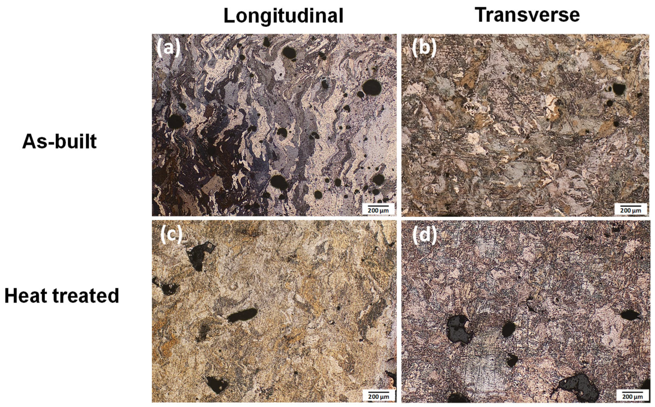
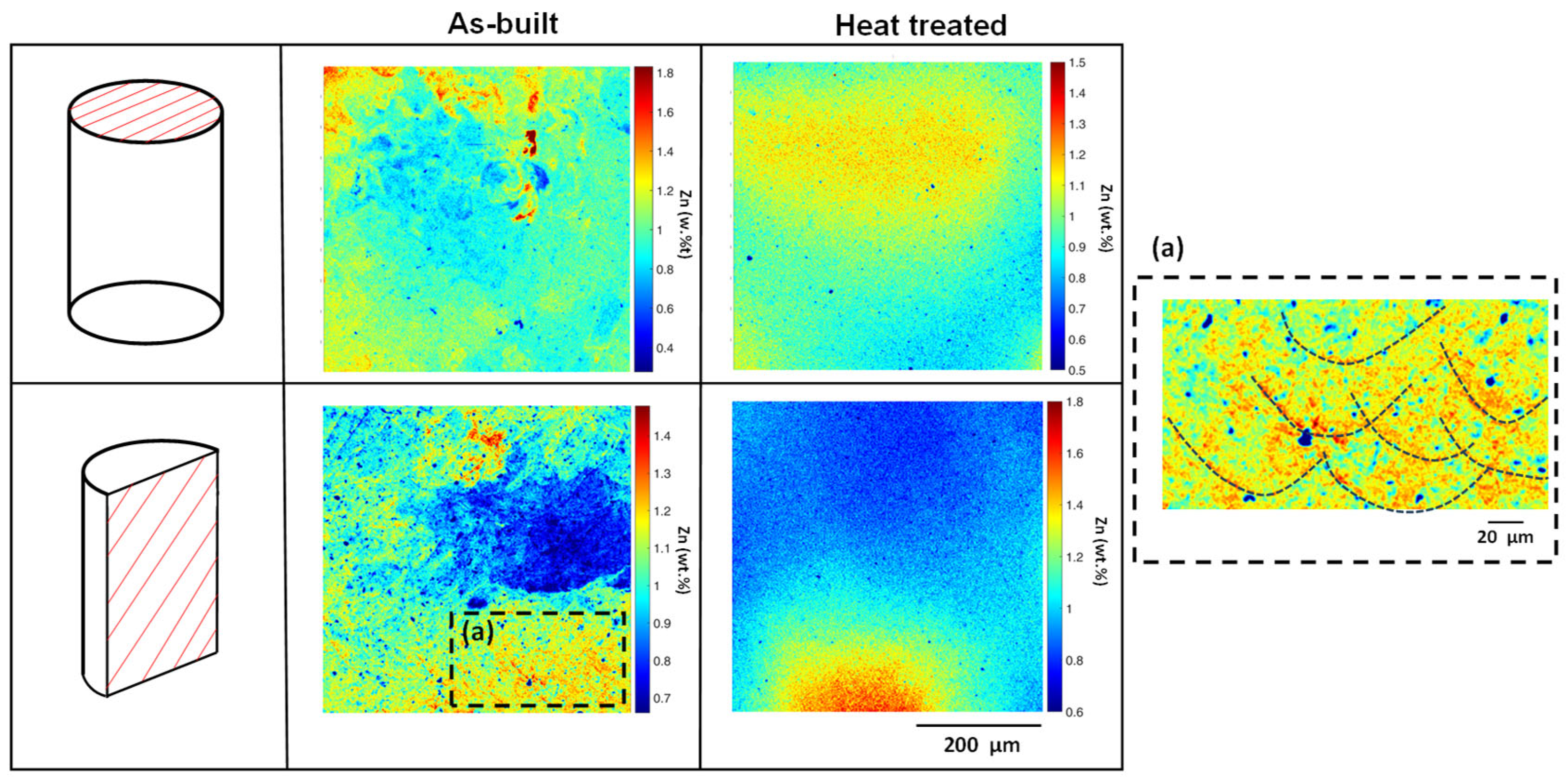
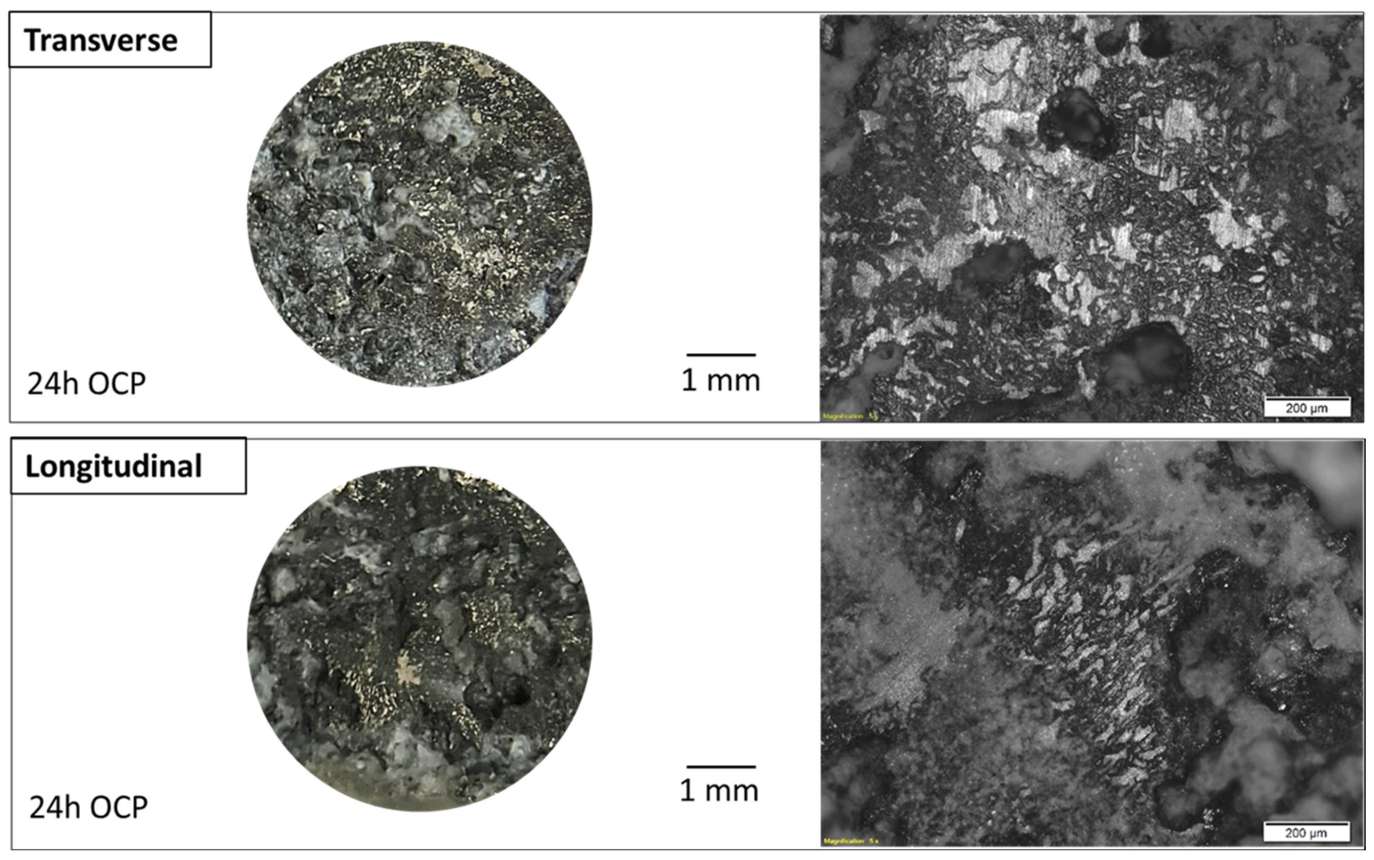
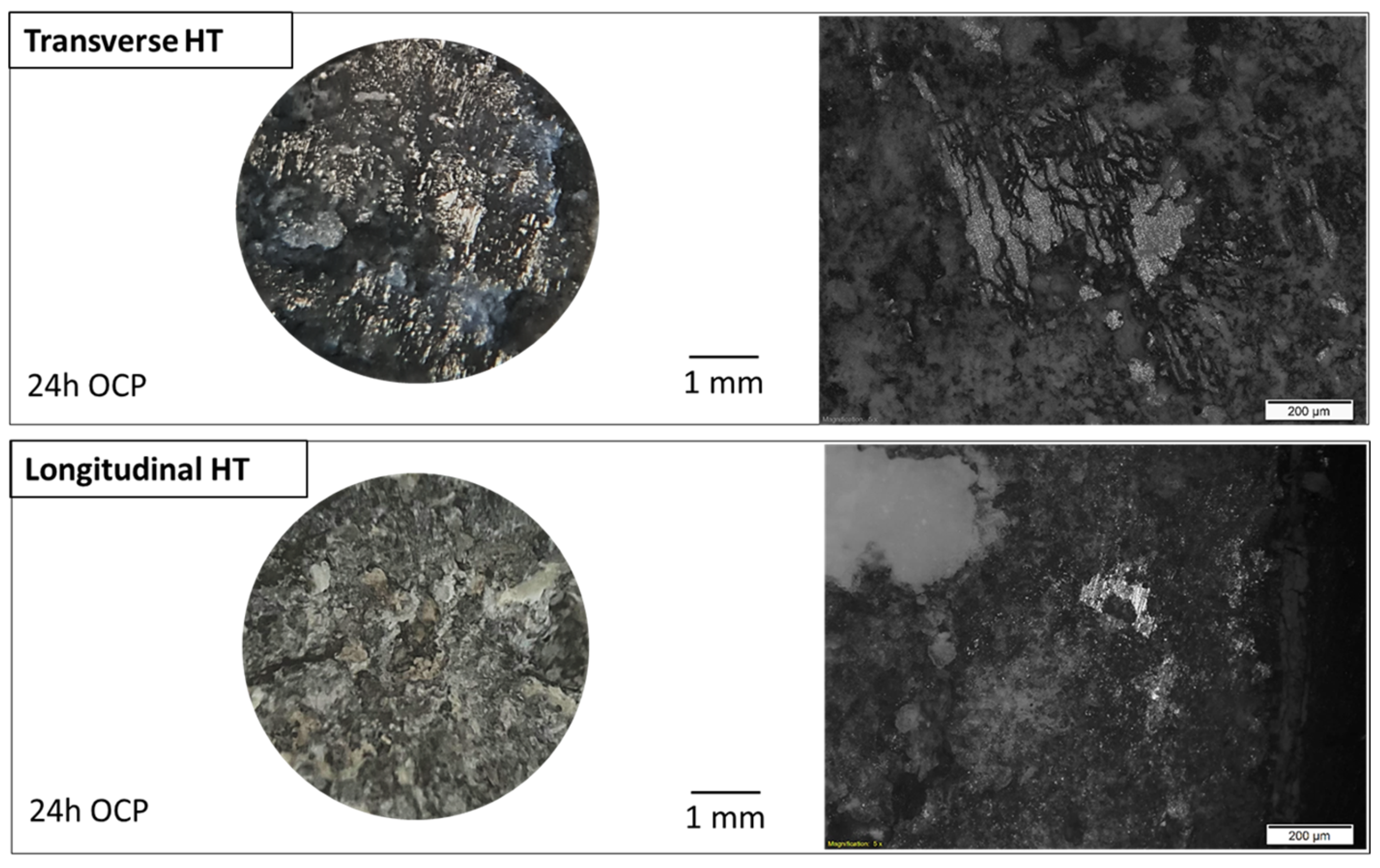
3.1. Microstructural Characterization

The Mg-1Zn alloy produced by LPBF exhibited a highly complex microstructure in the as-built condition, characterized by grains with irregular and anisotropic shapes, as well as the presence of grains with a pronounced columnar morphology aligned along the build direction, as shown in the optical micrographs in Figure 3a,b for the longitudinal and transverse sections, respectively. These figures show significant concavity in numerous grains, as well as some small grains completely enclosed by larger grains. The most notable feature of this microstructure is the presence of a multimodal grain size distribution. However, due to the anisotropic and complex morphology of the grains, conventional morphological descriptors based on idealized grain shapes are inadequate for determining an effective grain size or the collective anisotropy of grain boundary spacing.
The heterogeneous microstructure observed in the as-built alloy has been attributed to the abrupt temperature changes occurring in the melt pool during laser fusion and the subsequent rapid cooling. This rapid thermal cycling, inherent to the LPBF process, also results in the accumulation of internal stresses. In order to modify this microstructure and/or release residual stresses, post-build heat treatments are often applied to alloys to improve the properties. Since no specific heat treatment standards have been reported for LPBF Mg alloys to optimize their corrosion behavior, a homogenization treatment was selected, consisting of annealing at 350 °C for 24 h under high vacuum. This choice was based on the Mg-Zn phase diagram and the recrystallization temperature of magnesium-based alloys. Due to the high reactivity of Mg, the treatment was conducted under high vacuum and followed by furnace cooling to prevent oxidation. Only slight changes in the microstructure were observed after the heat treatment, as shown in the micrographs in Figure 3c,d for the longitudinal and transverse sections, respectively. A slight grain refinement was observed as a result of partial recrystallization within some columnar grains, indicating that the material tends to recrystallize during annealing. Additionally, pores characteristic of the LPBF processing [36] were found in all the planes and samples studied.
Second-phase particles may provide favorable sites for recrystallization but can also have a significant adverse effect on corrosion properties. Therefore, the presence of both MgO and intermetallic second-phase particles in the microstructure was further investigated using SEM on non-etched samples. Samples taken from both longitudinal and transverse sections revealed bright particles within the matrix, as shown in the micrographs in Figure 4a,b. EDS analysis of these bright particles (see Figure 4c) suggests that they are composed of magnesium oxide. The spectrum shows 61.39 at.% Mg and 38.61 at.% O, which deviates from the 1:1 atomic ratio expected for stoichiometric MgO. This discrepancy may be attributed to the small particle size (<10 μm) and the interaction volume extending into the underlying Mg matrix, which increases the detected Mg signal. Moreover, no evidence of intermetallic second phases was observed, confirming that Zn remained in solid solution within the Mg matrix.
Segregation is another important microstructural defect that arises during the LPBF manufacturing process and can negatively affect the corrosion behavior of the material. Figure 5 shows the Zn concentration maps in weight percentage obtained via EPMA after being mathematically processed by the method developed by Toda-Caraballo et al. to convert intensity to composition while minimizing noise [26]. In this figure, a heterogeneous distribution of Zn can be observed throughout the whole as-built sample, which in the longitudinal section tends to concentrate predominantly at the peripheries of the melt pools, as observed at higher magnifications in Figure 5(a). Figure 5 also shows that Zn distribution becomes more uniform across the transverse section of the sample after the homogenization treatment at 350 °C. However, annealing led to the development of larger and more Zn-enriched regions in specific areas of the longitudinal section, compared to those observed in the as-built condition. These features likely act as more electrochemically active cathodic sites, thereby increasing cathodic kinetics and potentially reducing corrosion resistance, as will be shown below.
Figure 6 shows the XRD patterns recorded for both the longitudinal and transverse planes in the as-built and heat-treated Mg-1Zn samples. The diffraction peaks shown in these patterns correspond exclusively to the α-Mg matrix and the MgO particles. Since up to 1.6 wt.% Zn may remain soluble in the Mg matrix at room temperature [37], no second intermetallic phases are expected in the microstructure. On the other hand, the relative intensity of some Mg diffraction peaks deviated from the ideal intensity for Mg reported on JCPDS card No. 35-0821. Although preferred orientation is generally the most common cause of XRD peak intensity mismatch, texture effects may also arise from the presence of coarse grains in the microstructure. To identify the presence of abnormally large grains contributing to diffraction, it was used a new approach consisting of recording a series of 2D X-ray patterns with a lab diffractometer in several randomly selected areas of the sample. The 2D diffraction pattern acquired with an area detector included the Debye rings corresponding to the 1D diffraction peaks shown in Figure 6. Figure 7 shows the Debye rings’ intensity associated with the longitudinal Mg-1Zn alloy in the as-built and HT conditions. The presence of a multimodal grain size distribution with coarse grains was concluded based on the observation that the recorded rings also included some diffraction spots, as previously shown in Figure 3a [38]. Although intensity depletion in some azimuths of the Debye rings would indicate the presence of a strong texture, the presence of spots in these rings indicates that the coarse diffraction grains represent a large fraction of the total area covered by the diameter of the incident beam, leading to a poor and skewed orientation distribution. On the other hand, notable differences in the intensity distribution along the Debye ring were found in four randomly selected areas of the as-built sample in the longitudinal section, as shown in Figure 7. The large crystallite size compared to the sampling volume does not enable an unambiguous characterization of the texture present in the material. In the case of the longitudinal HT specimens, Figure 7 shows the presence of a significantly lower amount of diffraction spots on the Debye rings together with a rather homogeneous intensity along. This could be attributed to the recrystallization process occurring during the treatment at 350 °C, which resulted in a more homogeneous and finer-grained microstructure. The rapid heating and cooling cycles inherent to the additive manufacturing process generate residual stresses that can promote recrystallization [39].
EBSD orientation maps depicted in Figure 8 confirm the highly complex and anisotropic grain morphology together with the grain refinement after the treatment at 350 °C, as observed in the optical micrographs of Figure 3. The columnar crystals present in the longitudinal section are mainly caused by the directional grain growth under thermal gradients during laser fusion and the subsequent extremely large cooling rates during the manufacturing process. Pole figure studies conducted via EBSD offer additional insights into the crystallographic texture of the samples, as shown in Figure 9. Since the texture in alloys processed by LPBF is primarily determined by the solidification mechanism, the presence of columnar grains aligned with the build direction and exhibiting strong <0001> crystallographic orientation is expected in Mg alloys. However, the presence of a multimodal grain size distribution with very coarse grains did not allow a sufficient volume to be scanned to unequivocally guarantee the presence of this texture in the as-built sample with our EBSD measurements. On the other hand, EBSD-Inverse pole figure (IPF), misorientation, and pole figure (PF) maps used to characterize the texture in Figure 8 revealed the presence of prismatic planes {11–20} and {10–10} in both sections of the heat-treated samples, and a reduction in the grain size, suggesting a more random texture. This observation is supported by the 2D diffraction patters of Figure 7 with a rather homogeneous intensity along the diffraction rings for this sample.

3.2. Potentiodynamic Polarization (PDP) Measurements

Figure 10 depicts the PDP measurements of the as-built and HT Mg-1Zn alloy specimens in 0.1 M NaCl solution in both the transverse and longitudinal planes. The analysis of cathodic kinetics of the as-built Mg-1Zn alloy revealed no significant differences between both sections in the proximity of the Ecorr, where ohmic potential effects are minimal (Figure 10a). However, variations were observed in the anodic kinetics, with the longitudinal plane demonstrating higher dissolution rates compared to the transverse plane. Conversely, the HT Mg-1Zn specimen exhibited slightly higher anodic and cathodic kinetics in the longitudinal plane compared to the transverse section (Figure 10b), suggesting that the heat treatment affected the electrochemical performance of the as-built alloy.
The differences in both anodic and cathodic kinetics observed may be attributed to the anisotropy in grain boundaries and morphology, and/or Zn distribution across the analyzed sections, associated with the manufacturing process. These microstructural variations are well-known to influence corrosion kinetics significantly. Previous studies by Ralston et al. [40], have explored the complex relationship between grain size and corrosion kinetics, highlighting that while grain refinement may enhance mechanical properties, it does not always translate to improved corrosion resistance. Therefore, the differences observed between the transverse and longitudinal planes are likely due to their different microstructures. However, separating the specific effects of grain size, precipitation, and other microstructural factors on overall corrosion behavior remains a significant challenge. This difficulty stems from the strong interdependence among these variables. For instance, thermomechanical treatments or alloying strategies intended to refine grain size often concurrently influence precipitation behavior and phase distribution. Consequently, isolating the contribution of each individual factor becomes complex, as modifications to one tend to induce simultaneous or even synergistic changes in others [41]. This intricate interplay highlights the need for carefully controlled experimental approaches aimed at disentangling their respective roles in corrosion mechanisms, which is not trivial. In this context, future work will focus on systematically investigating these parameters in isolation, with the goal of clarifying their specific influence on the corrosion response.
Figure 10c,d compare the cathodic and anodic curves before and after heat treatment, focusing on the regions near the Ecorr to facilitate the observation of differences in kinetics. The results indicate slight increased cathodic kinetics and decreased anodic kinetics compared to the as-built sample, in both planes examined. The observed enhancement of cathodic kinetics following annealing can be attributed to several microstructural factors. Primarily, the reduction in structural defects, such as dislocation density and grain boundary area, can facilitate more efficient electron transfer during the HER, which is the dominant cathodic process in magnesium and its alloys [5]. Furthermore, previous studies have shown the impact on corrosion kinetics of grain size and crystallographic orientation associated with the microstructural recrystallization induced by heat treatment [42,43]. Finally, the possibility of Zn segregation toward grain boundaries during annealing could contribute to the formation of localized cathodic sites that could enhance the rates of the cathodic reaction [40,44]. In brief, Zn-enriched grain boundaries exhibit a more noble (cathodic) behavior compared to the surrounding matrix. This electrochemical contrast promotes the formation of micro-galvanic couples between the Zn-rich grain boundaries and the Zn-depleted matrix; as a result, a continuous network of cathodic sites can form along the grain boundaries, creating a cathodic network that surrounds each grain and enhances the cathodic reaction, particularly HER [45]. This has been observed in Mg-Zn systems by Zheng et al. [46] and Shi et al. [47] after thermomechanical processing. To explore this hypothesis in more detail, EPMA analysis will be discussed below.
Regarding the anodic behavior, the decrease in anodic kinetics after the heat treatment is likely associated with the reduction of high-energy defect sites, which act as preferential locations for localized dissolution [40]. Thus, the observed electrochemical behavior reflects the complex interplay between microstructural evolution and surface chemistry, underscoring the critical role of post-processing treatments in tuning the corrosion resistance of additively manufactured Mg-Zn alloys. Future work will focus on isolating these individual factors to better clarify their specific contributions to corrosion mechanisms.
EPMA elemental mapping revealed a heterogeneous distribution of Zn throughout the entire as-built sample, whereas in the longitudinal section, Zn predominantly tended to concentrate at the peripheries of the melt pools, as shown at higher magnifications in Figure 5(a). Figure 5 also shows that Zn distribution becomes more uniform across the transverse section of the HT Mg-1Zn sample. However, localized Zn segregation persisted with a concomitant redistribution in specific areas of the longitudinal section after heat treatment. The initial Zn arrangement in the as-built Mg-1Zn microstructure may have introduced structural variations that remained even after prolonged annealing. These variations could have influenced the corrosion kinetics, potentially leading to the formation of new cathodic areas that enhanced the cathodic activity, as illustrated in Figure 10c,d.

3.3. Gravimetric HE Collection Measurements

Figure 11a shows the weight of accumulated H2 under OCP conditions during 24 h of immersion for the longitudinal and transverse sections of the as-built and the HT Mg-1Zn alloys in 0.1 M NaCl solution. Mean values of replicated experiments are shown, with error bars representing the standard deviation. No significant differences were observed within the first 3–4 h of testing, except for the curve corresponding to the as-built Mg-1Zn transverse plane, which exhibited a lower amount of H2 collected than the other specimens. However, different behaviors became evident after that initial period until the end of the test. Remarkable differences were observed for the longitudinal and transverse planes of the as-built Mg-1Zn sample, with higher values in the longitudinal section. This indicates higher corrosion kinetics in the longitudinal section compared to the transverse section, confirming the observations in Figure 10a. Note that at the OCP, charge conservation implies that the rates of the cathodic reaction must be equal to those of the anodic reaction (i.e., Mg corrosion). For the HT Mg-1Zn specimens, although differences between the longitudinal and transverse planes were also exhibited, they were significantly lower than those before heat treatment, which is also consistent with the PDP curves. Furthermore, it should be noted that the as-built Mg-1Zn longitudinal plane exhibited rather large deviations from the mean values. Considering the excellent sensitivity of the gravimetric method for H2 gas collection, this behavior was likely due to differences in the microstructure of the tested areas. As previously mentioned, all experiments were replicated several times to ensure reproducibility. Consequently, the remarkably large grain sizes revealed in Figure 3 and Figure 8 may have resulted in variations in the electrochemical response among experiments, depending on the area examined (i.e., different grains with distinct size and/or crystallographic orientation).
Figure 11b shows the instantaneous corrosion current density associated with the longitudinal and transverse sections for the as-built and HT Mg-1Zn alloys in 0.1 M NaCl solution, obtained from the evolution of the collected H2 shown in Figure 11a. The current density values were determined from the variation in the slope between consecutive discrete measurements. It can be observed that, although the longitudinal plane after the heat treatment exhibited the highest instantaneous corrosion current densities, these values were within the upper experimental variation shown by the as-built longitudinal section, indicating that both longitudinal planes exhibited the highest corrosion kinetics. After an initial peak with current density values in the range of 2–2.5 mA/cm2 at approximately 1.5 h, the corrosion kinetics for both planes decreased, then slowly increased again, ultimately reaching approximately 1.5 and 2 mA/cm2 after 24 h for the as-built and the HT Mg-1Zn specimens, respectively. In the case of the transverse section after heat treatment, lower corrosion current densities were observed, stabilizing around 1 mA/cm2 after about 6 h of testing. Finally, the as-built Mg-1Zn transverse section exhibited the lowest instantaneous corrosion rate, with values stabilizing at approximately 0.6 mA/cm2 after the same duration.
Several hypotheses can explain these differences in the measurement obtained at 24 h at OCP. One hypothesis is based on the surface appearance of both samples after 24 h at OCP, as shown in Figure 12. The longitudinal section exhibited more corrosion products than the transverse section, as indicated by the presence of darker regions. Both sets of images were acquired at the same magnification, allowing a direct visual comparison. Although the difference is slight, it may suggest a higher accumulation of corrosion products in the longitudinal section. Previous studies have shown that oxides may act as catalysts for hydrogen evolution [48,49,50]. Consequently, it is possible that the higher accumulation of corrosion products was responsible for the greater amount of H2 accumulation during the test. Additionally, a similar trend was observed for the HT Mg-1Zn specimen in both sections, as evidenced in Figure 13.

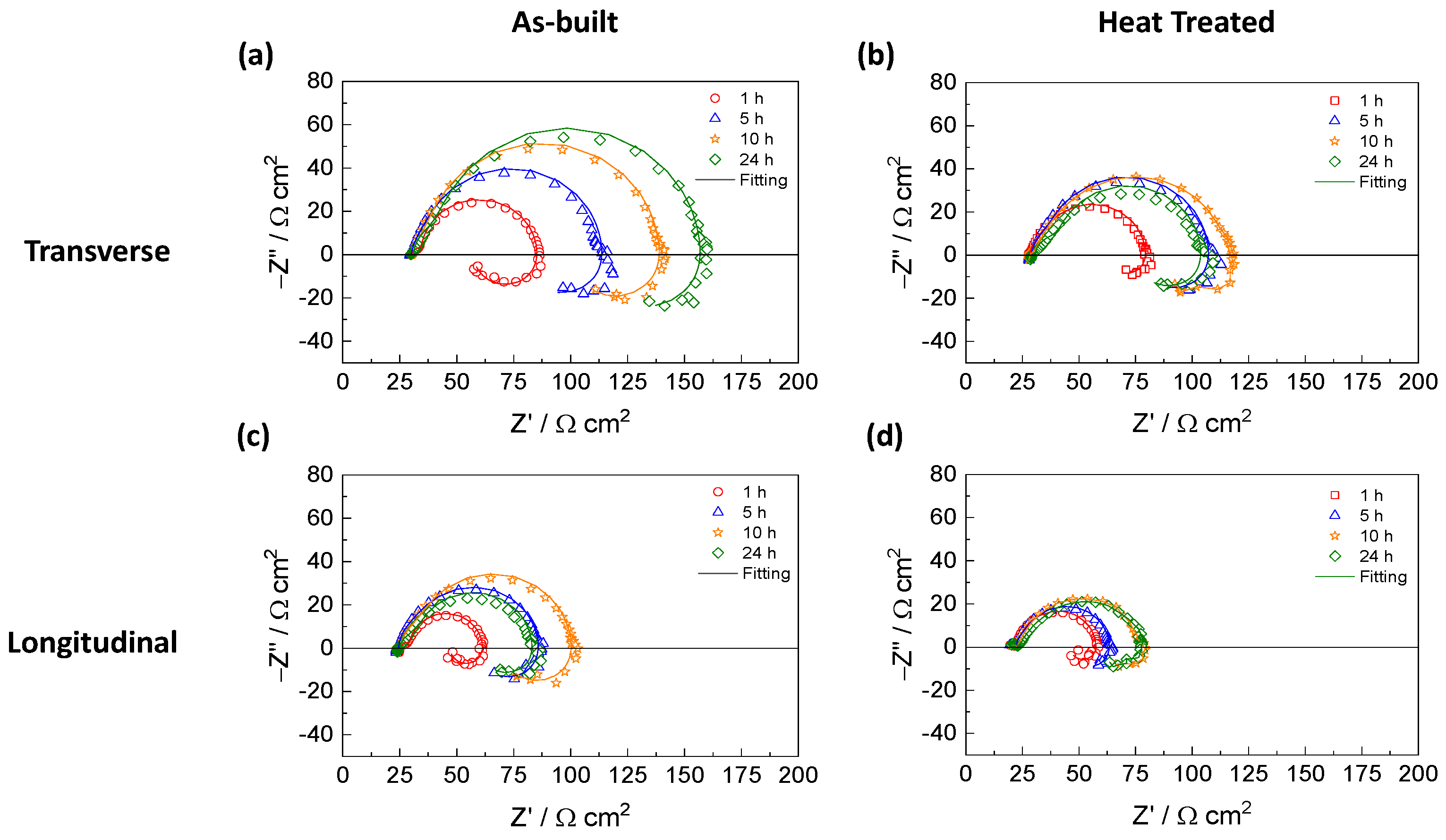
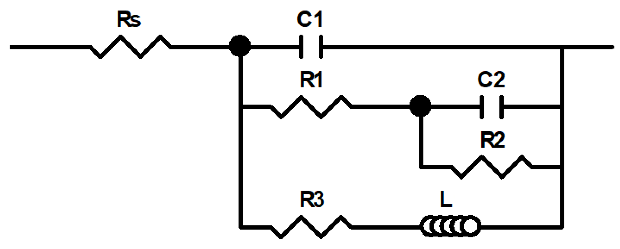
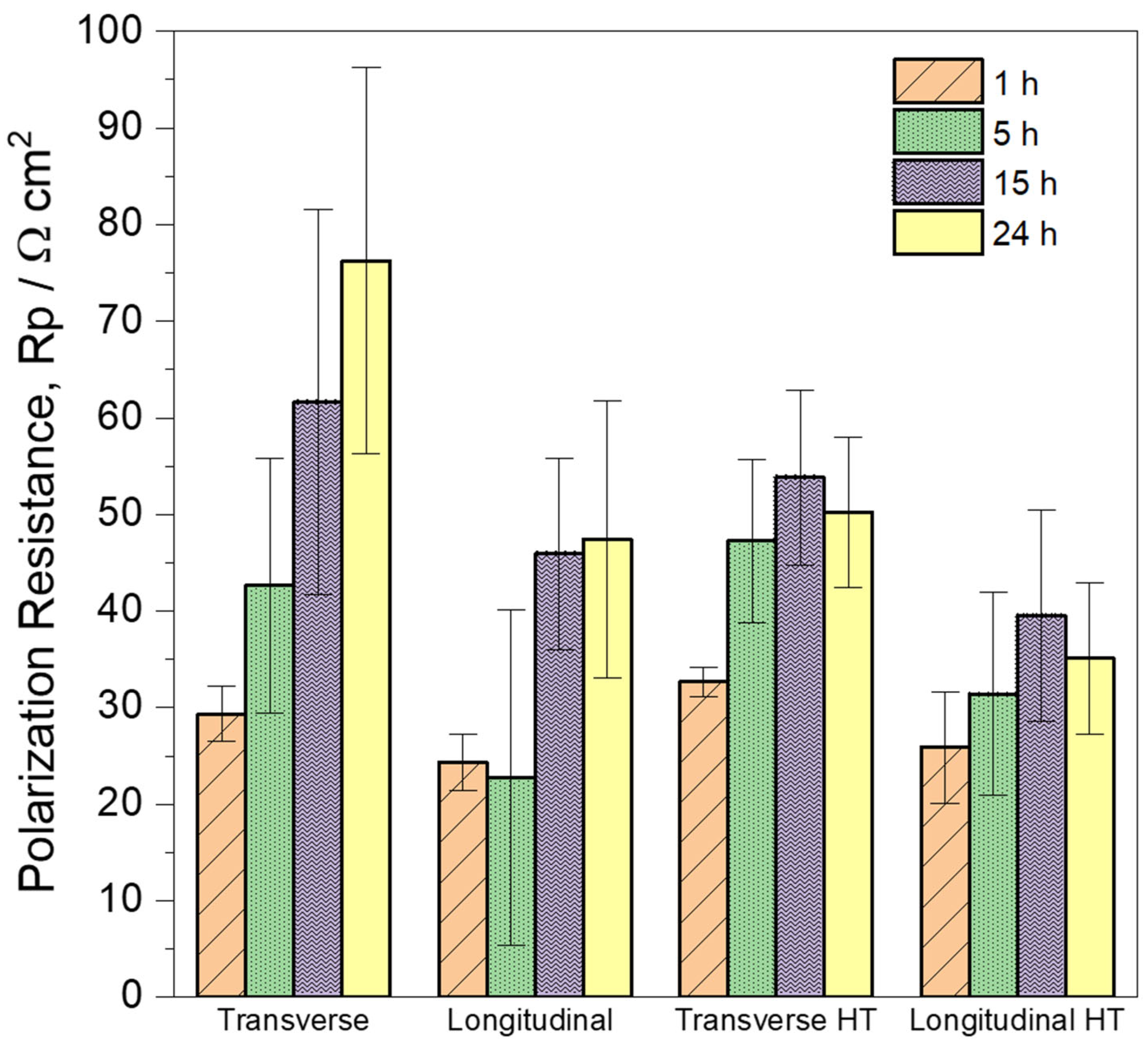
3.4. Electrochemical Impedance Spectroscopy (EIS) Measurements

Further insights into the corrosion resistance of the transversal and longitudinal sections of the Mg-1Zn alloy, both in its as-built condition and after heat treatment, were obtained by examining the EIS spectra recorded during the H2 collection measurements in a 0.1 M NaCl solution at various immersion times in Figure 11. The corresponding Nyquist plots are shown in Figure 14. First, the experimental data consistency was confirmed using Kramers–Kronig (K-K) transforms:
Z ω =   Z +   2 π   0 x Z x ω Z ( x ) x 2 ω 2 d x
Z ω = Z 0 + 2 π   0 ω / x Z x Z ( ω ) x 2 ω 2 d x
Z ω = 2 ω π   0 Z x Z ( ω ) x 2 ω 2 d x
where Z′(x) and Z″(x) represent the real and imaginary components of impedance, respectively, as they vary with angular frequency (x) within the range of 0 < x < ∞; Z′(ω) and Z″(ω) denote the real and imaginary parts of impedance at the specific angular frequency ω. The Kramers–Kronig (K-K) transforms enable the calculation of the imaginary impedance component from the measured real component and allow for comparison with the measured imaginary component (and vice versa). This comparison assesses the reliability of the experimental results.
Figure 15 and Figure 16 show the comparison between experimental and the KK-transformed data for the transverse and longitudinal planes of the as-built and HT Mg-1Zn specimens after being immersed in 0.1 M NaCl solution for 1 and 24 h, respectively. A good correlation between the experimental and transformed data was observed, even at low frequencies. Additionally, minimal residual errors confirmed the consistency and accuracy of the EIS experimental data.
Figure 14 shows that in the Nyquist plots of the transverse and longitudinal sections of the Mg-1Zn sample, both in the as-built condition and after heat treatment, two capacitive arcs can be observed. These arcs are characterized by a negative imaginary component (Z″) and an increasing real component (Z′) as the frequency decreases. Additionally, an inductive arc at the lowest frequency range was observed. Similar behavior has been documented in a myriad of studies on the corrosion of Mg alloys [51,52,53,54]. The exact cause of these inductive arcs is not well understood; however, it is often suggested that this phenomenon arises from the formation of intermediate species during the corrosion process and/or from actively corroding anodes, such as localized pits [55].
In the Nyquist plots depicted in Figure 14, the transverse as-built Mg-1Zn section showed a continuous increase in the resistive component of the real impedance from 1 h to 24 h. Conversely, in the other planes and samples studied, an increase was observed up to 10 h, followed by stabilization at 24 h or a slight reduction (notably observed in the longitudinal as-built Mg-1Zn). Specifically, the transverse section exhibited higher resistance compared to the longitudinal section in both samples before and after heat treatment, consistent with previous findings depicted in Figure 11, where the transverse section collected less H2 than the longitudinal section, indicating slower corrosion kinetics.
Comparing the effect of heat treatment, the transverse section showed a notable decrease in corrosion resistance compared to its as-built counterpart, while the longitudinal section exhibited a similar behavior. This is consistent with the observations presented above and suggests that the heat treatment process likely influenced the microstructural properties, leading to changes in the corrosion behavior of the alloy.
The equivalent electrical circuit (EEC) used to fit the experimental EIS data in Figure 14 is shown in Figure 17. This circuit, which has been used in a myriad of previous studies [56,57,58], has the minimum number of elements necessary to accurately reflect the experimental results and achieve a reasonable error when fitting the impedance data obtained. A detailed explanation of the physical significance of each electrical element in the EECs in Figure 17 is beyond the scope of this paper due to the ongoing discussion in the scientific community [59]. Nevertheless, Rs represents the electrolyte resistance between the working electrode (the Mg alloy) and the reference electrode. The first arc of the Nyquist diagram can be attributed to the capacitance (C1) and resistance (R1) of the oxide film [60]. The second arc could be associated with the double layer capacitance (C2) and charge transfer resistance (R2) [61], while the low-frequency arc (inductive loop), modeled by a series combination of an inductance loop (L) and a resistor (R3), can be attributed to the adsorption and desorption of intermediate species [51].
Table 2 and Table 3 show the fitting results for the transverse and longitudinal sections, comparing the as-built and heat-treated states, respectively. Mean values from replicated experiments with their relative errors are presented. Although C1 values obtained for both the transverse and longitudinal sections of the as-built and HT Mg-1Zn samples are slightly higher than those typically expected for an oxide film, this may be due to overlapping with the second time constant, which could result from the formation of a thin and/or poorly protective oxide layer [62]. Meanwhile, the values of C2 for all sections and samples studied are characteristic of an electric double layer, which aligns with the expected behavior of the second arc associated with double layer capacitance and charge transfer resistance.
Furthermore, the polarization resistance (Rp) can be estimated under DC current conditions (i.e., as the frequency approaches zero). In this condition, the impedance of capacitors tends towards infinity and that of inductors towards zero. Applying this to the EEC in Figure 17, the equivalent resistance can be determined as follows:
1 R p =   1 R 1 + R 2 +   1 R 3
Figure 18 shows the mean Rp values with their relative errors for the as-built and HT Mg-1Zn alloy in both transverse and longitudinal planes in 0.1 M NaCl solution at 1, 5, 15, and 24 h, calculated from the resistances shown in Table 2 and Table 3 using Equation (4). Figure 18 shows that in the as-built Mg-1Zn transverse plane, a constant increase in polarization resistance was observed throughout the entire duration of the experiment.
For the as-built Mg-1Zn longitudinal plane, a slight decrease in polarization resistance was observed from 1 to 5 h. However, this observation should be interpreted with caution, as the value at 5 h exhibited a large relative error and may not accurately reflect the true behavior. Finally, Rp increased after 15 h of immersion and remained relatively stable until the end of the test.
The transverse and longitudinal HT Mg-1Zn sections exhibited a similar behavior, with an increase in the polarization resistance until 15 h, followed by a decrease at 24 h. In decreasing order of polarization resistance at 24 h, the samples rank as follows: transverse as-built, transverse HT, longitudinal as-built, and longitudinal HT, which is in perfect agreement with the results presented in Figure 11.
In summary, EIS measurements indicate differences in corrosion behavior between the transverse and longitudinal sections in the as-built condition, with the transverse section exhibiting greater resistance. Following heat treatment, a decrease in corrosion resistance is observed compared to the as-built counterparts. These results are consistent with findings from H2 collection and PDP measurements.

4. Conclusions

The corrosion behavior of an additively manufactured Mg-1Zn alloy was investigated under both as-built and heat-treated conditions, with a specific focus on the transverse and longitudinal planes of cylindrical samples. The study employed microstructural characterization, gravimetric H2 collection, and electrochemical techniques. The principal conclusions drawn from this investigation are:
  • A Mg-1Zn alloy was successfully fabricated by laser powder bed fusion (LPBF), achieving density values of 97 ± 1% and 96 ± 2% for the transverse and longitudinal sections, respectively.
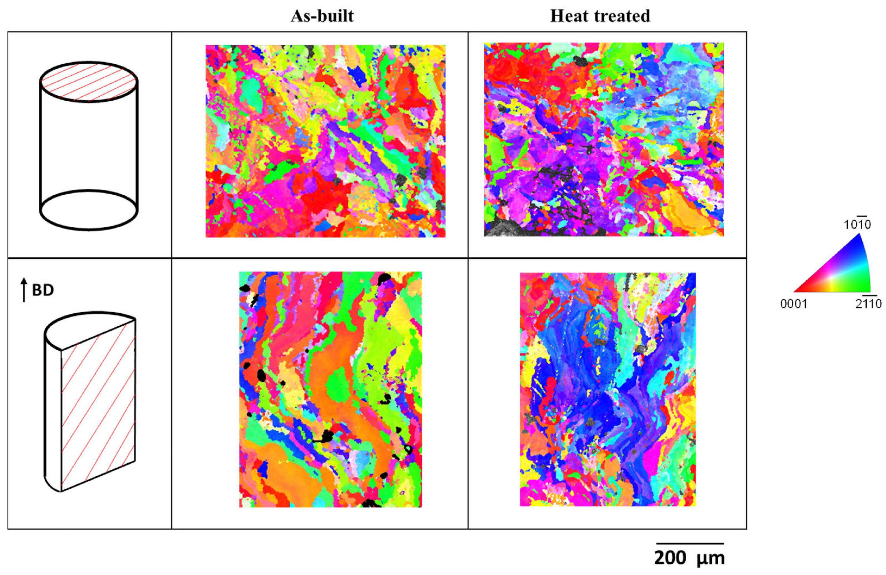
  • The as-built Mg-1Zn specimen showed irregular and anisotropic grain shapes with columnar morphology along the build direction. Only minor changes were observed after heat treatment, involving a slightly refinement of grain size.
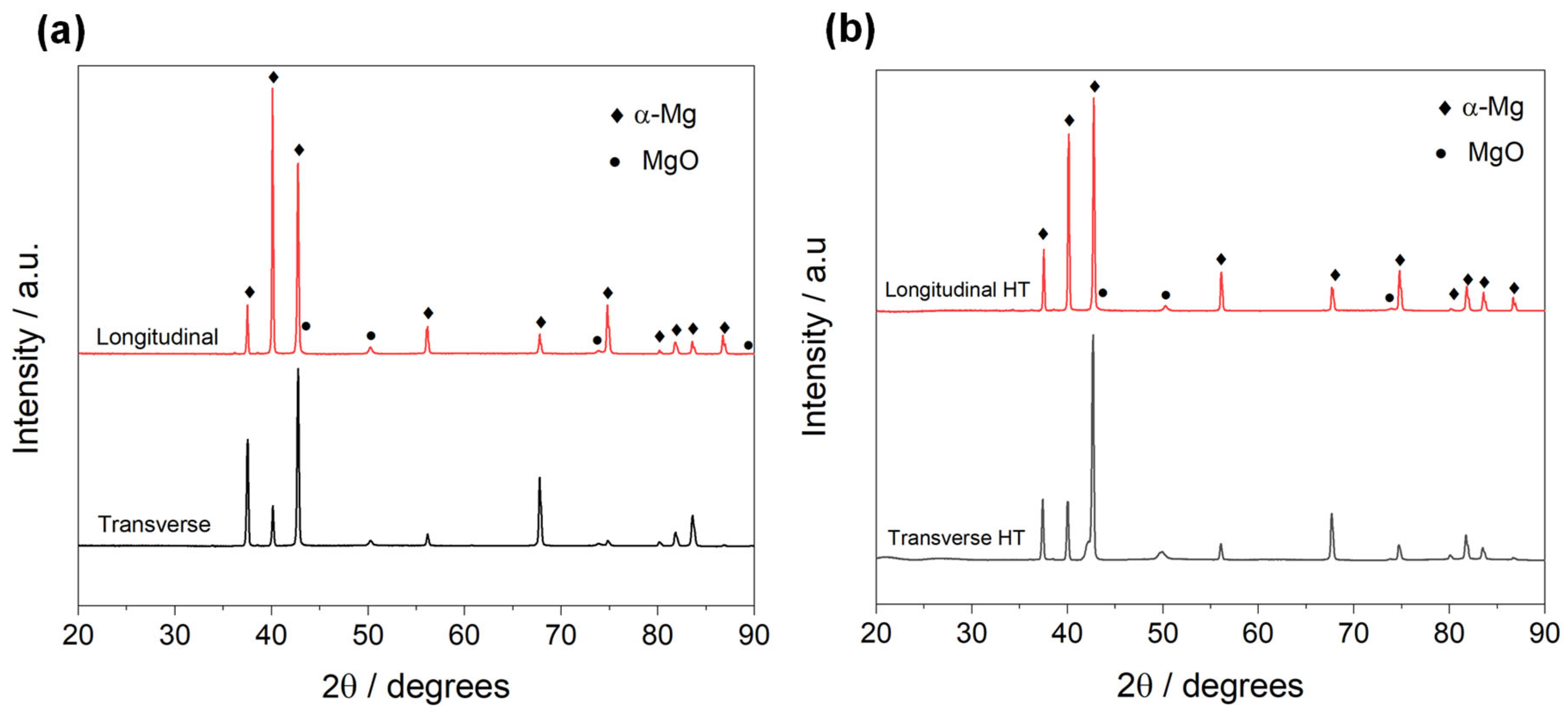
  • No presence of intermetallic secondary phases was observed through XRD and SEM in any plane studied, but the presence of Mg oxide was detected.
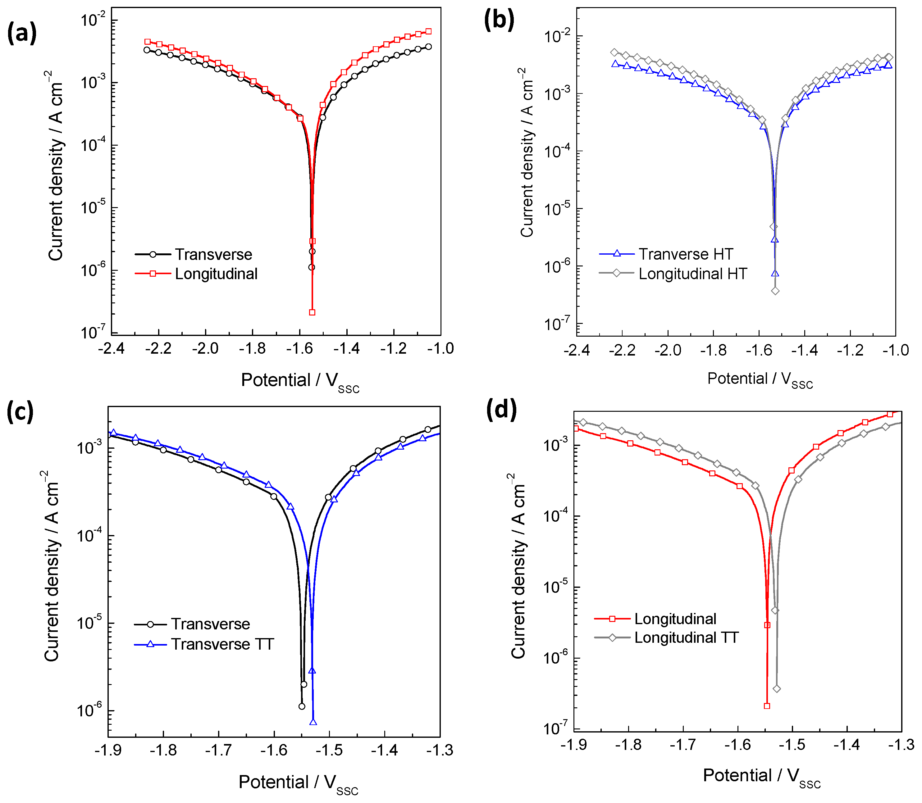
  • Regarding the alloy in the as-built state, the PDP curve showed that the longitudinal plane exhibited higher anodic kinetics than the transverse plane. This is consistent with the measurements obtained by EIS and H2 collection, demonstrating that the transverse plane presented greater corrosion resistance than the longitudinal plane.
  • Following heat treatment, both the transverse and longitudinal sections demonstrated an increase in cathodic kinetics and a decrease in anodic kinetics. Consequently, the corrosion resistance decreased in both sections after heat treatment.
  • The samples are ranked in increasing order of polarization resistance after 24 h of immersion as follows: longitudinal heat-treated, transverse heat-treated, longitudinal as-built, and transverse as-built.
  • The grain size and/or orientation are determining factors in the differences observed in corrosion resistance between the studied planes.

Author Contributions

R.R.-R.: Investigation, Writing—original draft, Writing—review and editing. Á.T.-P.: Writing—review and editing. F.G.-G.: Writing—review and editing. M.L.: Resources, Writing—review and editing. J.A.J.: Resources, Investigation, Writing—review and editing. S.F.: Conceptualization, Methodology, Investigation, Resources, Writing—original draft, Writing—review and editing, Supervision, Project administration, Funding acquisition. All authors have read and agreed to the published version of the manuscript.

Funding

Financial support under the Project PID2021-126166OB-I00, funded by MCIN/AEI/10.13039/501100011033 and by “ERDF A way of making Europe” (European Union); the Grant CNS2023-144665. funded by MCIN/AEI/10.13039/501100011033; and by the “European Union NextGenerationEU/PRTR”. S.F. and R.R.-R. thank the CSIC for the financial support under the project PIE-20216AT01.

Data Availability Statement

The raw data supporting the conclusions of this article will be made available by the authors on request.

Acknowledgments

The authors would like to express their gratitude to the CENIM-CSIC XRD, Optical Metallography, Additive Manufacturing and Electron Microscopy Laboratories. EPMA measurements were carried out at the ICTS-Centro Nacional de Microscopía Electrónica (UCM Madrid). The authors also wish to thank Roger Castellote for his valuable assistance with the processing of EPMA data. During the preparation of this manuscript, the authors used Chat Generative Pre-Trained Transformer (ChatGPT) developed by OpenAI, in order to improve its readability and language. After using this tool, the authors reviewed and edited the content as needed and take full responsibility for the content of the publication.

Conflicts of Interest

The authors declare that they have no known competing financial interests or personal relationships that could have appeared to influence the work reported in this paper. The authors declare no conflicts of interest.

References

  1. Aghion, E.; Bronfin, B.; Eliezer, D. The role of the magnesium industry in protecting the environment. J. Mater. Process. Technol. 2001, 117, 381–385. [Google Scholar] [CrossRef]
  2. Zhang, J.; Miao, J.; Balasubramani, N.; Cho, D.H.; Avey, T.; Chang, C.Y.; Luo, A.A. Magnesium research and applications: Past, present and future. J. Magnes. Alloy. 2023, 11, 3867–3895. [Google Scholar] [CrossRef]
  3. Fu, Q.; Liang, W.; Huang, J.; Jin, W.; Guo, B.; Li, P.; Xu, S.; Chu, P.K.; Yu, Z. Research perspective and prospective of additive manufacturing of biodegradable magnesium-based materials. J. Magnes. Alloy. 2023, 11, 1485–1504. [Google Scholar] [CrossRef]
  4. Cain, T.; Bland, L.G.; Birbilis, N.; Scully, J.R. A compilation of corrosion potentials for magnesium alloys. Corrosion 2014, 70, 1043–1051. [Google Scholar] [CrossRef] [PubMed]
  5. Esmaily, M.; Svensson, J.E.; Fajardo, S.; Birbilis, N.; Frankel, G.S.; Virtanen, S.; Arrabal, R.; Thomas, S.; Johansson, L.G. Fundamentals and advances in magnesium alloy corrosion. Prog. Mater. Sci. 2017, 89, 92–193. [Google Scholar] [CrossRef]
  6. Wu, Z.; Curtin, W.A. The origins of high hardening and low ductility in magnesium. Nature 2015, 526, 62–67. [Google Scholar] [CrossRef] [PubMed]
  7. Ahmad, R.; Yin, B.; Wu, Z.; Curtin, W.A. Designing high ductility in magnesium alloys. Acta Mater. 2019, 172, 161–184. [Google Scholar] [CrossRef]
  8. Zeng, Z.; Salehi, M.; Kopp, A.; Xu, S.; Esmaily, M.; Birbilis, N. Recent progress and perspectives in additive manufacturing of magnesium alloys. J. Magnes. Alloy. 2022, 10, 1511–1541. [Google Scholar] [CrossRef]
  9. Xu, W.; Li, J.; Zhang, Z.; Yuan, H.; An, G.; Shi, H.; Cai, C.; Jiang, W.; Li, W.; Wei, Q. Laser powder bed fusion of WE43 magnesium alloy with superior balance of strength and ductility. J. Magnes. Alloy. 2024, 13, 1275–1293. [Google Scholar] [CrossRef]
  10. Zhang, C.; Li, Z.; Zhang, J.; Tang, H.; Wang, H. Additive manufacturing of magnesium matrix composites: Comprehensive review of recent progress and research perspectives. J. Magnes. Alloy. 2023, 11, 425–461. [Google Scholar] [CrossRef]
  11. Shuai, C.; Yang, Y.; Wu, P.; Lin, X.; Liu, Y.; Zhou, Y.; Feng, P.; Liu, X.; Peng, S. Laser rapid solidification improves corrosion behavior of Mg-Zn-Zr alloy. J. Alloy. Compd. 2017, 691, 961–969. [Google Scholar] [CrossRef]
  12. Zengin, H.; Hassel, A.W. Magnesium alloys with rare earth elements—A review of the recent progress on the corrosion properties. Corros. Sci. 2014, 249, 112827. [Google Scholar] [CrossRef]
  13. Liu, Y.; Liu, D.; You, C.; Chen, M. Effects of grain size on the corrosion resistance of pure magnesium by cooling rate-controlled solidification. Front. Mater. Sci. 2015, 9, 247–253. [Google Scholar] [CrossRef]
  14. Liu, D.; Liu, Y.; Huang, Y.; Song, R.; Chen, M. Effects of solidification cooling rate on the corrosion resistance of Mg-Zn-Ca alloy. Prog. Nat. Sci. 2014, 24, 452–457. [Google Scholar] [CrossRef]
  15. Song, J.; Chen, J.; Xiong, X.; Peng, X.; Chen, D.; Pan, F. Research advances of magnesium and magnesium alloys worldwide in 2021. J. Magnes. Alloy. 2022, 10, 863–898. [Google Scholar] [CrossRef]
  16. Sames, W.J.; List, F.A.; Pannala, S.; Dehoff, R.R.; Babu, S.S. The metallurgy and processing science of metal additive manufacturing. Int. Mater. Rev. 2016, 61, 315–360. [Google Scholar] [CrossRef]
  17. Deng, Q.; Wu, Y.; Zhu, W.; Chen, K.; Liu, D.; Peng, L.; Ding, W. Effect of heat treatment on microstructure evolution and mechanical properties of selective laser melted Mg-11Gd-2Zn-0.4Zr alloy. Mater. Sci. Eng. A—Struct. Mater. Prop. Microstruct. Process. 2021, 829, 142139. [Google Scholar] [CrossRef]
  18. BNagesha, K.; Vinodh, K.; Tigga, A.K.; Barad, S.; Kumar, S.A. Influence of post-processing techniques on residual stresses of SLM processed HPNGV. J. Manuf. Process. 2021, 66, 189–197. [Google Scholar] [CrossRef]
  19. Cai, H.; Zhang, N.; Liu, L.; Su, J.; Li, Y.; Kang, Y.; Guo, F. Effects of cooling rate on the microstructure and properties of magnesium alloy-a review. J. Magnes. Alloy. 2024, 12, 3094–3114. [Google Scholar] [CrossRef]
  20. Sefene, E.M. State-of-the-art of selective laser melting process: A comprehensive review. J. Manuf. Syst. 2021, 63, 250–274. [Google Scholar] [CrossRef]
  21. Chowdhury, S.; Yadaiah, N.; Prakash, C.; Ramakrishna, S.; Dixit, S.; Gupta, L.R.; Buddhi, D. Laser powder bed fusion: A state-of-the-art review of the technology, materials, properties & defects, and numerical modelling. J. Mater. Res. Technol.-JMRT 2022, 20, 2109–2172. [Google Scholar] [CrossRef]
  22. Niu, X.; Shen, H.; Fu, J.; Yan, J.; Wang, Y. Corrosion behaviour of laser powder bed fused bulk pure magnesium in hank’s solution. Corros. Sci. 2019, 157, 284–294. [Google Scholar] [CrossRef]
  23. Esmaily, M.; Zeng, Z.; Mortazavi, A.N.; Gullino, A.; Choudhary, S.; Derra, T.; Benn, F.; D’Elia, F.; Müther, M.; Thomas, S.; et al. A detailed microstructural and corrosion analysis of magnesium alloy WE43 manufactured by selective laser melting. Addit. Manuf. 2019, 35, 101321. [Google Scholar] [CrossRef]
  24. Zumdick, N.A.; Jauer, L.; Kersting, L.C.; Kutz, T.N.; Schleifenbaum, J.H.; Zander, D. Additive manufactured WE43 magnesium: A comparative study of the microstructure and mechanical properties with those of powder extruded and as-cast WE43. Mater. Charact. 2018, 147, 384–397. [Google Scholar] [CrossRef]
  25. Wei, K.; Gao, M.; Wang, Z.; Zeng, X. Effect of energy input on formability, microstructure and mechanical properties of selective laser melted AZ91D magnesium alloy. Mater. Sci. Eng. A—Struct. Mater. Prop. Microstruct. Process. 2014, 611, 212–222. [Google Scholar] [CrossRef]
  26. Jiang, P.; Blawert, C.; Zheludkevich, M.L. The Corrosion Performance and Mechanical Properties of Mg-Zn Based Alloys—A Review. Corros. Mater. Degrad. 2020, 1, 92–158. [Google Scholar] [CrossRef]
  27. Yin, P.; Li, N.F.; Lei, T.; Liu, L.; Ouyang, C. Effects of Ca on microstructure, mechanical and corrosion properties and biocompatibility of Mg–Zn–Ca alloys. J. Mater. Sci.: Mater. Med. 2013, 24, 1365–1373. [Google Scholar] [CrossRef] [PubMed]
  28. Wei, K.; Zeng, X.; Wang, Z.; Deng, J.; Liu, M.; Huang, G.; Yuan, X. Selective laser melting of Mg-Zn binary alloys: Effects of Zn content on densification behavior, microstructure, and mechanical property. Mater. Sci. Eng. A—Struct. Mater. Prop. Microstruct. Process. 2019, 756, 226–236. [Google Scholar] [CrossRef]
  29. Taheri-Andani, M.; Zhang, Z.; Sundararaghavan, V.; Misra, A. Mapping the roles of scan strategy and build orientation in predicting the crystallographic texture and yield strength of 316L stainless steel produced by laser powder bed fusion. J. Mater. Res. Technol. 2024, 30, 7375–7383. [Google Scholar] [CrossRef]
  30. Dejene, N.D.; Tucho, W.M.; Lemu, H.G. Effects of Scanning Strategies, Part Orientation, and Hatching Distance on the Porosity and Hardness of AlSi10Mg Parts Produced by Laser Powder Bed Fusion. J. Manuf. Mater. Process. 2025, 9, 78. [Google Scholar] [CrossRef]
  31. Zhou, F.; Lu, S.S.; Jiang, B.; Song, R.G. Effect of annealing treatment of hot-rolled AZ31 magnesium alloy on properties and stress corrosion resistance of MAO coatings. Anti-Corros. Methods Mater. 2024, 71, 403–416. [Google Scholar] [CrossRef]
  32. Wang, S.; Wang, Y.; Ramasse, Q.M.; Fan, Z. Grain refinement of Mg-Ca alloys by native MgO particles. J. Magnes. Alloy. 2024, 12, 980–996. [Google Scholar] [CrossRef]
  33. Garcés, G.; Pérez, P.; Medina, J.; Barea, R.; Gómez, A.; García, J.; Adeva, P. On the Influence of Precipitation on the Dynamic Strain Aging in Mg-2%Nd. JOM 2023, 75, 2385–2396. [Google Scholar] [CrossRef]
  34. Curioni, M. The behaviour of magnesium during free corrosion and potentiodynamic polarization investigated by real-time hydrogen measurement and optical imaging. Electrochim. Acta 2014, 120, 284–292. [Google Scholar] [CrossRef]
  35. Fajardo, S.; Frankel, G.S. Gravimetric Method for Hydrogen Evolution Measurements on Dissolving Magnesium. J. Electrochem. Soc. 2015, 162, C693–C701. [Google Scholar] [CrossRef]
  36. Wu, C.L.; Xie, W.J.; Man, H.C. Laser additive manufacturing of biodegradable Mg-based alloys for biomedical applications: A review. J. Magnes. Alloy. 2014, 10, 915–937. [Google Scholar] [CrossRef]
  37. Toda-Caraballo, I.; Jiménez, J.A.; Milenkovic, S.; Jimenez-Aguirre, J.; San-Martin, D. Microstructural Stability of the CoCrFe2Ni2 High Entropy Alloys with Additions of Cu and Mo. Metals 2021, 11, 1994. [Google Scholar] [CrossRef]
  38. Bramble, M.S.; Flemming, R.L.; McCausland, P.J.A. Grain size measurement from two-dimensional micro-X-ray diffraction: Laboratory application of a radial integration technique. Am. Miner. 2015, 100, 1899–1911. [Google Scholar] [CrossRef]
  39. Manjhi, S.K.; Sekar, P.; Bontha, S.; Balan, A.S.S. Additive manufacturing of magnesium alloys: Characterization and post-processing. Int. J. Lightweight Mater. Manuf. 2024, 7, 184–213. [Google Scholar] [CrossRef]
  40. Ralston, K.D.; Birbilis, N.; Davies, C.H.J. Revealing the relationship between grain size and corrosion rate of metals. Scr. Mater. 2010, 63, 1201–1204. [Google Scholar] [CrossRef]
  41. Ahmadkhaniha, D.; Fedel, M.; Sohi, M.H.; Deflorian, F. Corrosion behavior of severely plastic deformed magnesium based alloys: A review. Surf. Eng. Appl. Electrochem. 2017, 53, 439–448. [Google Scholar] [CrossRef]
  42. Hagihara, K.; Okubo, M.; Yamasaki, M.; Nakano, T. Crystal-orientation-dependent corrosion behaviour of single crystals of a pure Mg and Mg-Al and Mg-Cu solid solutions. Corros. Sci. 2016, 109, 68–85. [Google Scholar] [CrossRef]
  43. Liu, B.; Liu, X.; Wu, P.; Zhang, S.; Zhang, Y.; Zhang, Z.; Wang, H. Microstructure and corrosion behavior of a hot-rolled pure Mg after annealing at various temperatures. Mater. Today Commun. 2024, 39, 109104. [Google Scholar] [CrossRef]
  44. Ralston, K.D.; Birbilis, N. Effect of Grain Size on Corrosion: A Review. Corrosion 2010, 66, 075005-1–075005-13. [Google Scholar] [CrossRef]
  45. Liu, X.; Shan, D.; Song, Y.; Han, E. Effects of heat treatment on corrosion behaviors of Mg-3Zn magnesium alloy. Trans. Nonferrous Met. Soc. China 2010, 20, 1345–1350. [Google Scholar] [CrossRef]
  46. Zheng, R.; Bhattacharjee, T.; Gao, S.; Gong, W.; Shibata, A.; Sasaki, T.; Hono, K.; Tsuji, N. Change of Deformation Mechanisms Leading to High Strength and Large Ductility in Mg-Zn-Zr-Ca Alloy with Fully Recrystallized Ultrafine Grained Microstructures. Sci. Rep. 2019, 9, 11702. [Google Scholar] [CrossRef]
  47. Shi, D.F.; Cepeda-Jiménez, C.M.; Pérez-Prado, M.T. The relation between ductility at high temperature and solid solution in Mg alloys. J. Magnes. Alloy. 2022, 10, 224–238. [Google Scholar] [CrossRef]
  48. Fajardo, S.; Glover, C.F.; Williams, G.; Frankel, G.S. The Source of Anodic Hydrogen Evolution on Ultra High Purity Magnesium. Electrochim. Acta 2016, 212, 510–521. [Google Scholar] [CrossRef]
  49. Salleh, S.H.; Thomas, S.; Yuwono, J.A.; Venkatesan, K.; Birbilis, N. Enhanced hydrogen evolution on Mg(OH)2 covered Mg surfaces. Electrochim. Acta 2015, 161, 144–152. [Google Scholar] [CrossRef]
  50. Lebouil, S.; Duboin, A.; Monti, F.; Tabeling, P.; Volovitch, P.; Ogle, K. A novel approach to on-line measurement of gas evolution kinetics: Application to the negative difference effect of Mg in chloride solution. Electrochim. Acta 2014, 124, 176–182. [Google Scholar] [CrossRef]
  51. Gomes, M.P.; Costa, I.; Pébère, N.; Rossi, J.L.; Tribollet, B.; Vivier, V. On the corrosion mechanism of Mg investigated by electrochemical impedance spectroscopy. Electrochim. Acta 2019, 306, 61–70. [Google Scholar] [CrossRef]
  52. Leleu, S.; Rives, B.; Bour, J.; Causse, N.; Pébère, N. On the stability of the oxides film formed on a magnesium alloy containing rare-earth elements. Electrochim. Acta 2018, 290, 586–594. [Google Scholar] [CrossRef]
  53. García-Galvan, F.R.; Fajardo, S.; Barranco, V.; Feliu, S. Experimental apparent stern–geary coefficients for AZ31B Mg alloy in physiological body fluids for accurate corrosion rate determination. Metals 2021, 11, 391. [Google Scholar] [CrossRef]
  54. Fajardo, S.; Miguélez, L.; Arenas, M.A.; de Damborenea, J.; Llorente, I.; Feliu, S. Corrosion resistance of pulsed laser modified AZ31 Mg alloy surfaces. J. Magnes. Alloy. 2022, 10, 756–768. [Google Scholar] [CrossRef]
  55. Yang, Y.; Scenini, F.; Stevens, N.; Curioni, M. Relationship between the inductive response observed during electrochemical impedance measurements on aluminium and local corrosion processes. Corros. Eng. Sci. Technol. 2019, 54, 1–9. [Google Scholar] [CrossRef]
  56. Hernández, L.; González, J.E.; Barranco, V.; Veranes-Pantoja, Y.; Galván, J.C.; Gattorno, G.R. Biomimetic hydroxyapatite (HAp) coatings on pure Mg and their physiological corrosion behavior. Ceram. Int. 2022, 48, 1208–1222. [Google Scholar] [CrossRef]
  57. Bland, L.G.; King, A.D.; Birbilis, N.; Scully, J.R. Assessing the corrosion of commercially pure magnesium and commercial AZ31B by electrochemical impedance, mass-loss, hydrogen collection, and inductively coupled plasma optical emission spectrometry solution analysis. Corrosion 2015, 71, 128–145. [Google Scholar] [CrossRef]
  58. Curioni, M.; Scenini, F.; Monetta, T.; Bellucci, F. Correlation between electrochemical impedance measurements and corrosion rate of magnesium investigated by real-time hydrogen measurement and optical imaging. Electrochim. Acta 2015, 166, 372–384. [Google Scholar] [CrossRef]
  59. Wang, L.; Snihirova, D.; Deng, M.; Wang, C.; Vaghefinazari, B.; Wiese, G.; Langridge, M.; Höche, D.; Lamaka, S.V.; Zheludkevich, M.L. Insight into physical interpretation of high frequency time constant in electrochemical impedance spectra of Mg. Corros. Sci. 2021, 187, 109501. [Google Scholar] [CrossRef]
  60. Deng, M.; Wang, L.; Höche, D.; Lamaka, S.V.; Wang, C.; Snihirova, D.; Jin, Y.; Zhang, Y.; Zheludkevich, M.L. Approaching ‘stainless magnesium’ by Ca micro-alloying. Mater. Horiz. 2021, 8, 589–596. [Google Scholar] [CrossRef]
  61. Li, Y.; Lu, X.; Wu, K.; Yang, L.; Zhang, T.; Wang, F. Exploration the inhibition mechanism of sodium dodecyl sulfate on Mg alloy. Corros. Sci. 2020, 168, 108559. [Google Scholar] [CrossRef]
  62. Gharbi, O.; Tran, M.T.T.; Orazem, M.E.; Tribollet, B.; Turmine, M.; Vivier, V. Impedance Response of a Thin Film on an Electrode: Deciphering the Influence of the Double Layer Capacitance. ChemPhysChem 2021, 22, 1371–1378. [Google Scholar] [CrossRef]
Figure 1. (a) SEM image and (b) particle size distribution of Mg-1Zn powder.
Metals 15 00853 g001
Figure 2. (a) Schematic of the additive manufacturing machine operation, depicting layer-wise laser orientation, (b) representation of printed cylinders displaying the transverse and longitudinal planes, along with build direction (BD), and (c) representative optical micrograph of both sections of the as-built Mg-1Zn sample.
Metals 15 00853 g002
Figure 3. Micrographs of (a) longitudinal and (b) transverse sections of Mg-1Zn alloy in the as-built condition, and (c) longitudinal and (d) transverse sections after heat treatment.
Metals 15 00853 g003
Figure 4. Scanning electron microscopy (SEM) images of (a) longitudinal and (b) transverse sections of the Mg-1Zn alloy. (c) Energy-dispersive X-ray spectroscopy (EDS) analysis of a bright particle observed in the microstructure.
Metals 15 00853 g004
Figure 5. Electron probe microanalysis (EPMA) images of the Mg-1Zn alloy in transverse and longitudinal sections, both in the as-built condition and after heat treatment. The scale bar represents wt.% of Zn. (a) Magnified view of the transverse as-built section.
Metals 15 00853 g005
Figure 6. X-ray diffraction (XRD) patterns for samples (a) in the as-built state and (b) after heat treatment (HT).
Metals 15 00853 g006
Figure 7. Debye ring intensity of Mg-1Zn in the as-built and heat-treated longitudinal section.
Metals 15 00853 g007
Figure 8. EBSD orientation maps and corresponding inverse pole figures (IPF) of transverse and longitudinal sections of the Mg-1Zn alloy, both in the as-built condition and after heat treatment.
Metals 15 00853 g008
Figure 9. Pole figure of transverse and longitudinal sections of the Mg-1Zn alloy, both as-built and after heat treatment. The color scale represents crystal orientation density in multiples of a uniform distribution (m.u.d.). Red areas indicate high orientation density, while blue areas correspond to low density.
Metals 15 00853 g009
Figure 10. Potentiodynamic polarization curves for the longitudinal and transverse sections of the Mg-1Zn alloy in (a) as-built and (b) heat-treated conditions, in 0.1 M NaCl solution. Experiments were performed from the OCP, scanning upwards to 0.5 V vs. the OCP (anodic) and downwards to −0.7 V vs the OCP (cathodic) at a scan rate of 1 mV s−1. Comparison of the cathodic and anodic curves presented in (c,d) before and after heat treatment. Only the regions near the Ecorr are shown, facilitating the observation of differences in kinetics.
Metals 15 00853 g010
Figure 11. (a) H2 weight collected over a 24 h period at the OCP for all studied planes, and (b) instantaneous corrosion current density of the studied sections over the same 24 h period.
Metals 15 00853 g011
Figure 12. Surface appearance of the transverse and longitudinal sections of the as-built Mg-1Zn specimen in 0.1 M NaCl solution after 24 h of immersion at OCP.
Metals 15 00853 g012
Figure 13. Surface appearance of the transverse and longitudinal sections of the HT Mg-1Zn specimen in 0.1 M NaCl solution after 24 h of immersion at OCP.
Metals 15 00853 g013
Figure 14. Nyquist plots at different immersion times for the as-built Mg-1Zn (a) transverse and (c) longitudinal planes, and the HT Mg-1Zn (b) transversal and (d) longitudinal planes.
Metals 15 00853 g014
Figure 15. Comparison of the experimental and KK-transformed EIS data after 1 h of immersion in 0.1 M NaCl solution for the as-built Mg-1Zn (a) transverse and (c) longitudinal planes, and the HT Mg-1Zn (b) transversal and (d) longitudinal planes.
Metals 15 00853 g015
Figure 16. Comparison of the experimental and KK-transformed EIS data after 24 h of immersion in 0.1 M NaCl solution for the as-built Mg-1Zn (a) transverse and (c) longitudinal planes, and the HT Mg-1Zn (b) transversal and (d) longitudinal planes.
Metals 15 00853 g016
Figure 17. Electrical equivalent circuit (EEC) used to model the EIS spectra presented in Figure 14 for the longitudinal and transverse sections of the as-built and HT Mg-1Zn specimens immersed in 0.1 M NaCl solution.
Metals 15 00853 g017
Figure 18. Polarization resistance (Rp) values for the Mg-1Zn in transverse and longitudinal sections, in both as-built and heat-treated conditions. Mean values from replicated experiments are presented. Error bars are standard deviation.
Metals 15 00853 g018
Table 1. Chemical composition (wt.%) of the Mg-1Zn alloy powder used for LPBF.
AlloyZnAlCuFeMnNiSiMg
Mg-1Zn1.100.0020.0010.0010.040.0020.001Bal.
Table 2. Fitting results of EIS experimental data for the transverse as-built and HT Mg-1Zn alloy after different immersion times in 0.1 M NaCl solution. The mean values and their corresponding standard deviations for each element in the EEC shown in Figure 17 are presented.
As-Built Heat-Treated
1 h5 h10 h24 h1 h5 h10 h24 h
Rs(Ω cm2)29.3 ± 0.930 ± 0.331 ± 0.431 ± 0.430.2 ± 1.930.4 ± 1.230.8 ± 1.031.6 ± 0.4
C1(µF cm−2)14 ± 173 ± 1054 ± 832 ± 6108 ± 166 ± 343 ± 225 ± 1
R1(Ω cm2)7 ± 134 ± 1138 ± 1635 ± 1018 ± 121 ± 220 ± 317 ± 2
C2(µF cm−2)73 ± 10120 ± 7387 ± 2059 ± 12150 ± 14 94 ± 681 ± 882 ± 10
R2(Ω cm2)54 ± 9 43 ± 1864 ± 2593 ± 2131 ± 155 ± 1168 ± 14 67 ± 12
L(H cm2)149 ± 282384 ± 4392538 ± 2384581 ± 13491696 ± 3122362 ± 6792132 ± 3352094 ± 511
R3(Ω cm2)57 ± 297 ± 21161 ± 29189 ± 5598 ± 6125 ± 24139 ± 18125 ± 17
Table 3. Fitting results of EIS experimental data for the longitudinal as-built and HT Mg-1Zn alloy after different immersion times in 0.1 M NaCl solution. The mean values and their corresponding standard deviations for each element in the EEC shown in Figure 17 are presented.
As-Built Heat-Treated
1 h5 h15 h24 h1 h5 h14 h24 h
Rs(Ω cm2)24 ± 224 ± 125.5 ± 0.625.0 ± 0.822.0 ± 0.422.8 ± 0.3 23.2 ± 0.823.5
± 0.4
C1(µF cm−2)18 ± 586 ± 966 ± 847 ± 6100 ± 3086 ± 466 ± 449 ± 8
R1(Ω cm2)5.5 ± 0.527 ± 530 ± 623 ± 810 ± 2 21 ± 623 ± 618 ± 3
C2(µF cm−2)126 ± 11150 ± 56130 ± 41112 ± 15146 ± 22163 ± 23157 ± 26152 ± 39
R2(Ω cm2)35 ± 532 ± 543 ± 1048 ± 727 ± 528 ± 637 ± 735 ± 8
L(H cm2)145 ± 691331 ± 3262026 ± 5442110 ± 696581 ± 1091535 ± 3132281± 3221415 ± 268
R3(Ω cm2)61 ± 650 ± 44124 ± 26150 ± 5887 ± 2691 ± 43118 ± 45104 ± 26
Disclaimer/Publisher’s Note: The statements, opinions and data contained in all publications are solely those of the individual author(s) and contributor(s) and not of MDPI and/or the editor(s). MDPI and/or the editor(s) disclaim responsibility for any injury to people or property resulting from any ideas, methods, instructions or products referred to in the content.

