Article

Phase Transformations During Heat Treatment of a CPM AISI M4 Steel

by
Maribel L. Saucedo-Muñoz
1,
Valeria Miranda-Lopez
1,
Felipe Hernandez-Santiago
1,
Carlos Ferreira-Palma
2 and
Victor M. Lopez-Hirata
1,*
1
Instituto Politecnico Nacional (ESIQIE-ESIME), Mexico City 07308, Mexico
2
Facultad de Química, Universidad Veracruzana, Boca del Rio 94294, Mexico
*
Author to whom correspondence should be addressed.
Metals 2025, 15(7), 818; https://doi.org/10.3390/met15070818
Submission received: 8 June 2025 / Revised: 9 July 2025 / Accepted: 16 July 2025 / Published: 21 July 2025
(This article belongs to the Special Issue Advances in Steels: Heat Treatment, Microstructure and Properties)

Abstract

The phase transformations of Crucible Particle Metallurgy (CPM) American Iron and Steel Institute (AISI) M4 steel were studied during heat treatments using a CALPHAD-based method. The calculated results were compared with experimental observations. The optimum austenitizing temperature was determined to be about 1120 °C using Thermo-Calc software (2024b). Air-cooling and quenching treatments led to the formation of martensite with a hardness of 63–65 Rockwell C (HRC). The annealing treatment promoted the formation of the equilibrium ferrite and carbide phases and resulted in a hardness of 24 HRC. These findings with regard to phases and microconstituents are in agreement with the predictions derived from a Thermo-Calc-calculated time–temperature–transformation diagram at 1120 °C. Additionally, the primary carbides, MC and M6C, which formed prior to the heat treatment and had a minor influence on the quenched hardness. In contrast, the tempering process primarily led to the formation of fine secondary M6C carbides, which hardened the tempered martensite to 57 HRC. The present work demonstrates the application of a CALPHAD-based methodology to the design and microstructural analysis of tool steels.

1. Introduction

AISI M4 steel is a high-speed tool steel with a high content of Cr, Mo, V, Cr, and C which is usually fabricated by powder metallurgy PM [1,2,3]. The formation of different carbides in a martensitic phase promotes good wear resistance and cutting-edge stability [4,5]. The typical application for M4 steel is the fabrication of shearing and cutting tools. Thus, this tool steel requires toughness, wear resistance, and resistance to softening [6,7,8]. Crucible Particle Metallurgy (CPM) M4 steel is fabricated by powder metallurgy, which offers a viable alternative for producing steel with a uniform distribution of fine carbides. This microstructure can help to confer good mechanical properties [1,9]. These mechanical properties are typically obtained through heat treatments.
The heat treatment of this steel consists of austenitizing, which is followed by quenching and tempering and results in a hardness between 58 and 66 HRC [4]. The formation of tempered martensite provides fundamental strength and toughness during the quenching and tempering of M4 steel. In contrast, carbide formation improves the wear resistance of this steel [1,4]. Tool steels contain carbides such as V-rich MC, W and Mo-rich M6C, Mo-rich M2C, Cr-rich M7C3, and Cr-rich M23C6 [1,4,6]. These carbides can precipitate from the austenite phase during austenitizing, and they are referred to as primary carbides. Nevertheless, some carbides can also be formed during tempering, and these are designated as secondary carbides. The higher the content of C and strong carbide-forming elements, the higher the volume fraction of carbides. Additionally, the higher the carbide volume fraction, the higher the hardness and wear resistance; however, the toughness of the tool steel decreases as the carbide volume fraction increases [7,8]. The total carbide volume fraction is about 0.3 for most high-speed tool steels.
These steels exhibit high hardness but low Charpy-impact energy at room temperature—lower than 20 J [1]. Therefore, their machinability is poor, and thus, this steel may be resulfurized to improve it. The austenitizing temperatures are between 1025 and 1205 °C for 5–45 min, and this step is followed by quenching in vacuum, warm oil, or salt. Tempering is carried out immediately after quenching at temperatures between 538 and 593 °C for 2 h. Double or triple tempering is typically required for austenitizing temperatures exceeding 1149 °C. AISI M4 steel is also widely used as a hard coating in cladding materials [6,7,8,9,10,11].
Phase transformations and heat treatments for various alloys can be analyzed using CALPHAD-based software such as Thermo-Calc 2024b [12]. However, no publications reporting the application of Themo-Calc to phase transformations for AISI M4 steel has been reported in the literature [13,14]. For instance, primary carbide precipitation in the austenite matrix during austenitizing can be analyzed using the TC-PRISMA software (2024b) [15]. That is, the growth kinetics of precipitation can be analyzed to determine its effect on mechanical properties. Additionally, Thermo-Calc software [16] enables the determination of equilibrium phases for a multicomponent alloy. In addition, this software enables us to calculate non-equilibrium diagrams, such as time–temperature–transformation (TTT) and continuous-cooling–transformation (CCT) diagrams. These diagrams aid in designing appropriate heat treatments for the steel to achieve good mechanical properties.
Thus, this work aims to analyze the microstructural changes associated with heat treatment of a CPM AISI M4 steel and their effect on mechanical properties using a CALPHAD-based method.

2. Materials and Methods

2.1. Numerical Methodology

Thermo-Calc TC software 2024b [16], which employs a CALPHAD-based method, was used to analyze the phase transformations of the work steel under both equilibrium and non-equilibrium conditions. The data fed to the software primarily included the chemical composition and temperature. Additionally, TC-PRISMA [16] was utilized to study the precipitation of the α phase in the γ austenite. The precipitation was assumed to be intragranular. This software also calculates the interfacial energy between the matrix and precipitate. TC-PRISMA is based on Langer–Schwartz theory and utilizes the Kampmann–Wagner numerical method for the concurrent simulation of nucleation, growth, and coarsening of dispersed phases in a matrix phase [17]. The time–temperature–transformation (TTT) diagram was also calculated for this precipitation using TC-PRISMA. The input data for this case also include the chemical composition of the steel, temperature and time of aging, nucleation site, and initial microstructure. TC-PRISMA utilizes equilibrium parameters calculated with Thermo-Calc and kinetic parameters obtained from TC-DICTRA to evaluate the intragranular precipitation kinetics [16]. The following TC-PRISMA parameters were used to simulate the precipitation of ferrite in austenite: a grain aspect ratio of 1.0, an austenite grain size of 5 μm, a dislocation density of 5 × 10⁻² cm−2, and an interfacial energy between the precipitate and the matrix of 0.2 Jm−2. Grain size and morphology showed almost no change with heat treatment and time. For the intragranular precipitation of carbides in austenite, the precipitate morphology was spherical and the interfacial energies were 0.1974 and 0.1532 Jm−2 for the interface between austenite and MC carbide and the interface between austenite and M6C carbide, respectively. The time–temperature–transformation (TTT) diagram was calculated using the Steel Model Library in Thermo-Calc. For instance, the pearlite and bainite formations are based on a model that incorporates the nucleation rate, growth rate, and overall transformation kinetics, considering all primary theoretical ingredients previously reported in the literature [18,19]. Likewise, the martensite-formation simulation is based on a thermodynamic and driving force to describe the transformation curve [20]. The calculations in the present work utilize the Thermo-Calc Fe thermodynamic database v.11.0 and the Thermo-Calc mobility Fe databases v. 6.0 [16].

2.2. Experimental Methodology

The actual chemical composition of the CPM AISI M4 steel is shown in Table 1. This analysis was carried out with a Avanta atomic-absorption spectroscope (CBG, Ciudad de Mexico, Mexico). The bulk steel received corresponds to a cutting tool fabricated by powder metallurgy. This steel is a high-carbon steel with a high content of strong carbide-forming elements, such as Cr, Mo, V, and W. Additionally, a high S content is also present. This finding suggests that a high volume fraction of MnS inclusions is expected to improve the machinability of this hard steel. Steel specimens of about 1 cm × 1 cm × 1 cm were cut using a MINITOM cutting machine (Struers, Copenhagen, Denmark) with a diamond disk. These specimens were austenitized at 1120 °C for 30 min using a Chamber Furnace (CARBOLITE, Hope Valley, Derbyshire, UK). One specimen was a furnace-cooled, annealed sample and was designated specimen A. The second specimen was an air-cooled sample and was designated specimen AC. The last was quenched in a molten salt bath at 540 °C and then air-cooled; this sample represented the quenched condition and was designated specimen Q. Another quenched sample was triple-tempered at 540 °C for 2 h, resulting in a sample representing the quenched–tempered condition and designated specimen Q-T. The heat-treated specimens were analyzed by X-ray diffraction (XRD) to identify the phases present in the heat-treated steel with a IV Ultima diffractometer (Rigaku, The Woodlands, TX, USA) using monochromatic Co Kα radiation. These specimens were metallographically prepared using emery paper up to 1200 grit and polished with alumina of 1 and 0.05 μm particle size. Nital 5, composed of 5 mL HNO3 in 95 mL ethanol, was employed to reveal the steel microstructure. A MA200 optical microscope (OM) (Nikon, Tokyo, Japan) and JSM 6300 and JSM 6701F scanning electron microscopes (SEM) (JEOL, Tokyo, Japan) at 20 kV, equipped with EDX analysis, were utilized to observe the steel microstructure. An EDX-SEM element-mapping technique was employed to identify the carbide type. Finally, the Rockwell C hardness was determined for each steel specimen, following the procedure established in the ASTM E-18 standard [21] in a DT-10 Rockwell testing machine (Mitutoyo, Kawasaki, Japan). Quantitative metallography of microstructures was performed using ImageJ software (NIH, Bethesda, MD, USA) to quantify carbide size and volume fraction using SEM micrographs.

3. Results and Discussion

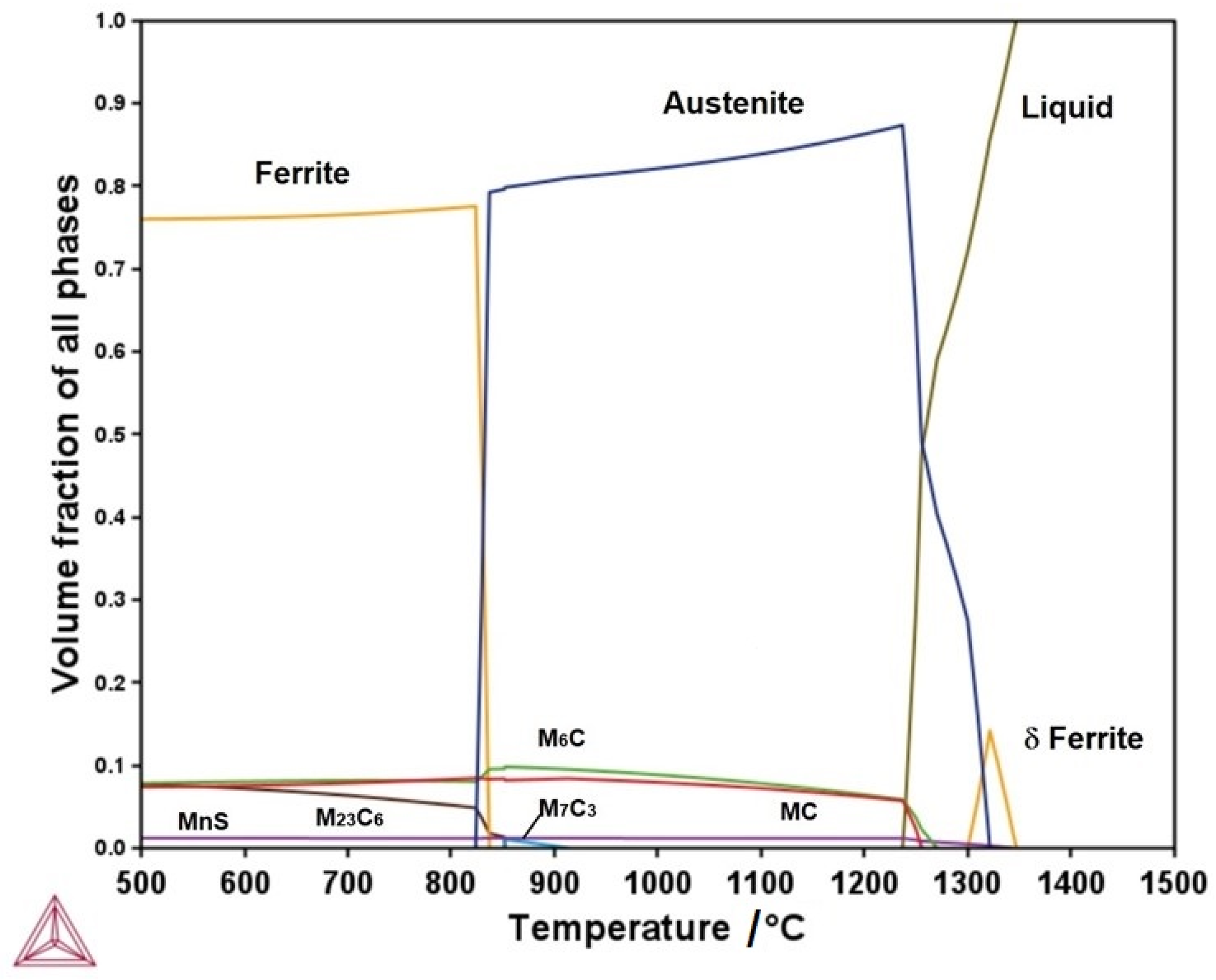
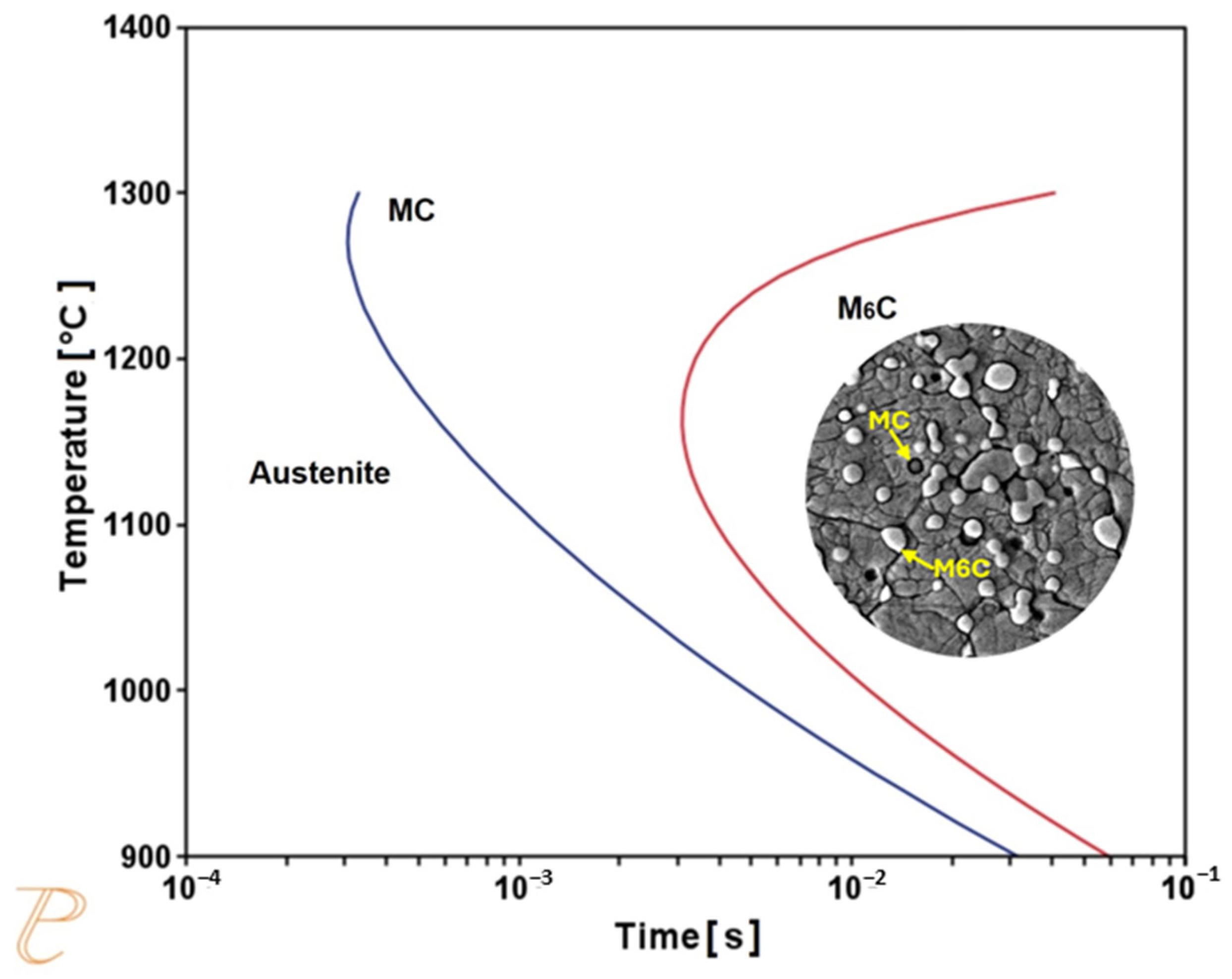
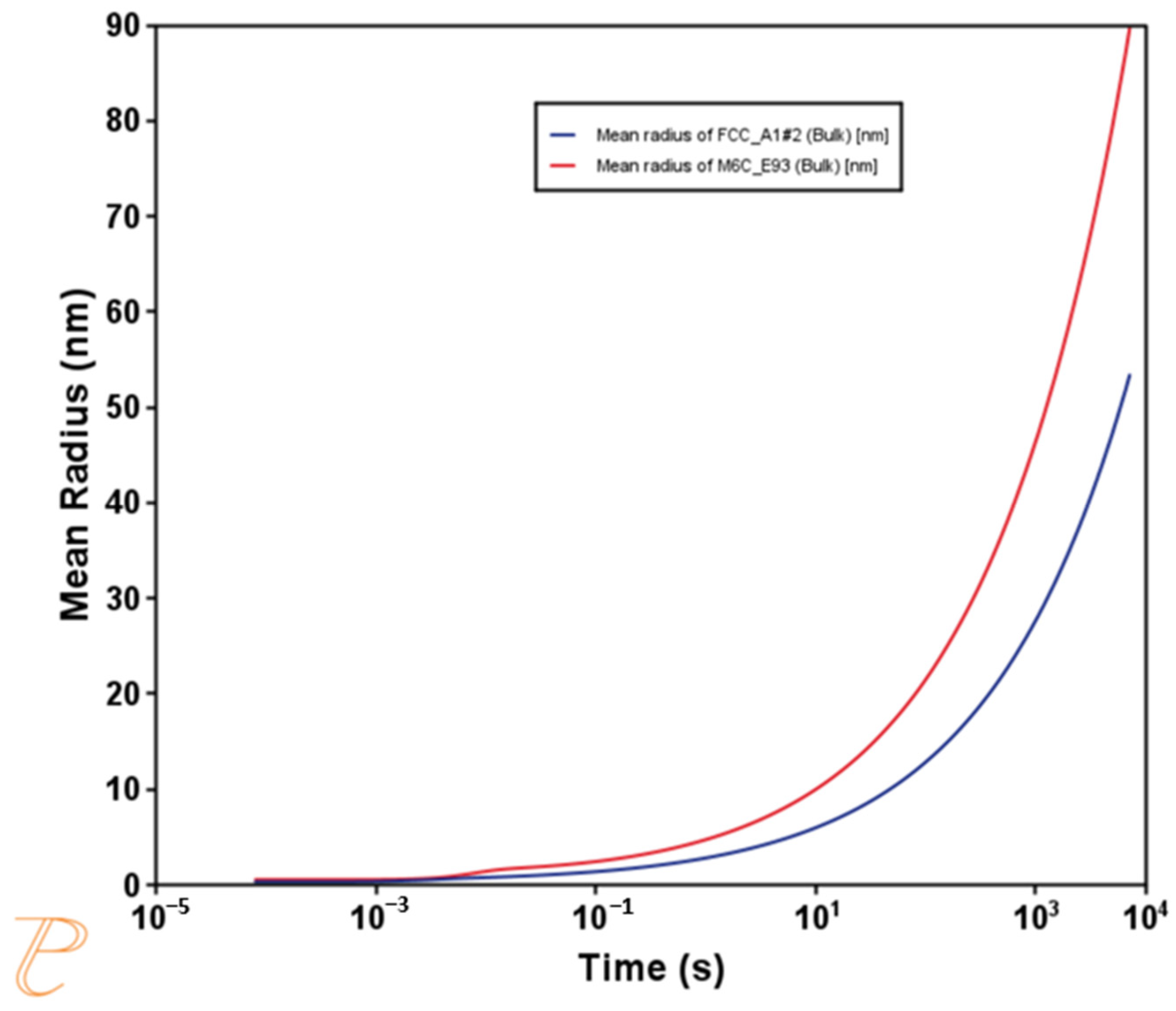
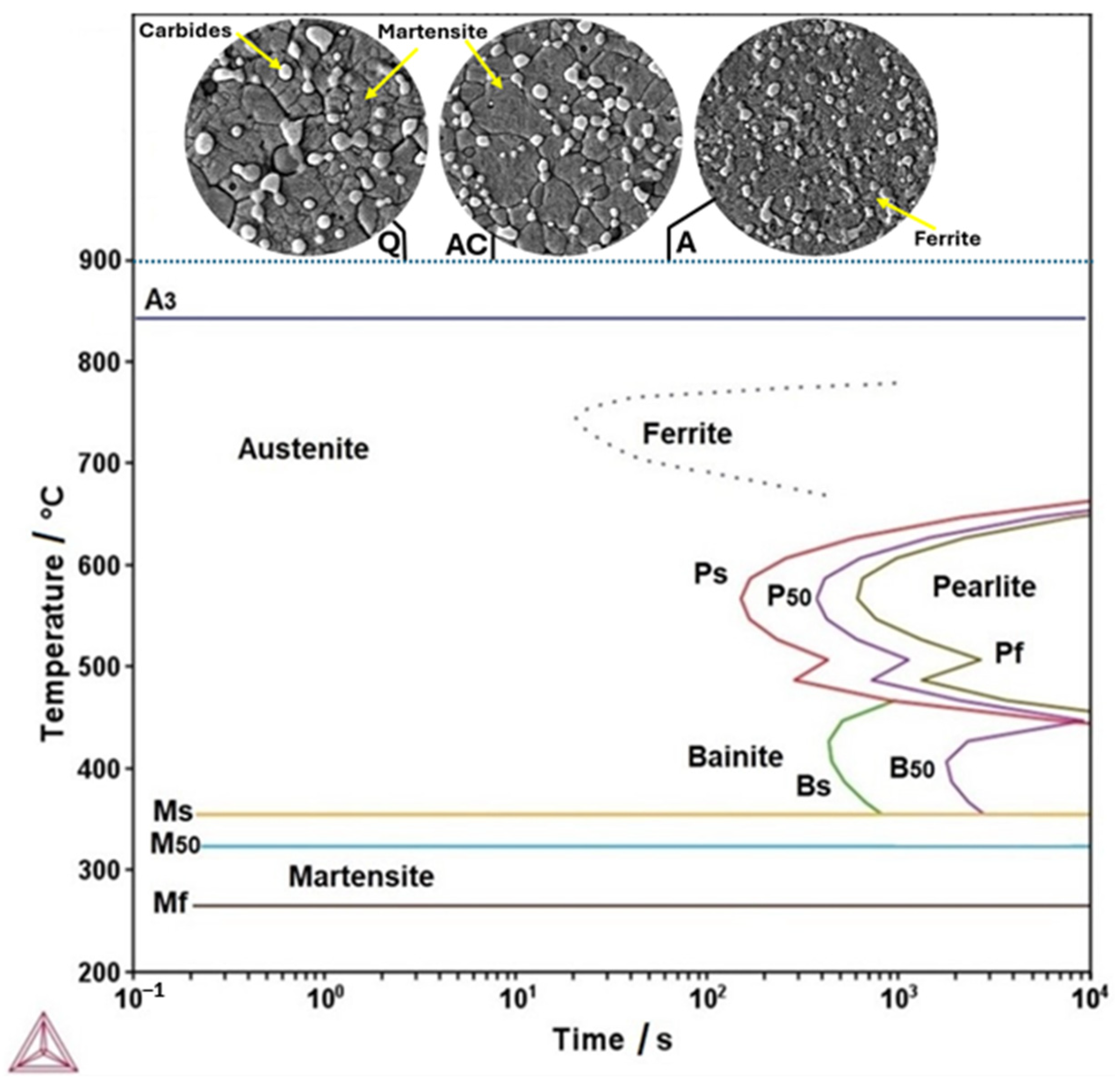
3.1. Themo-Calc Analysis of Equilibrium and Nonequilibrium Phases

Figure 1 presents the Thermo-Calc TC-calculated plot of the volume fraction of equilibrium phases versus temperature. The equilibrium condition is achieved using a very slow cooling rate and is obtained only in annealing. The AISI M4 steel was fabricated using powder metallurgy; however, this diagram is useful for understanding the phase formation that occurs in the transition from high temperatures to low ones. The liquid phase is present at temperatures above 1365 °C. The first solid phase corresponds to the δ ferrite, which appears at about 1345 °C. This phase reaches a maximum volume fraction of approximately 0.14 (14 vol. %) at 1320 °C. The austenite phase begins to form at approximately 1324 °C. Its volume fraction reaches a maximum of 0.88 (88 vol. %) at 1231 °C. The inclusions of MnS are formed at approximately 1340 °C in the δ ferrite field and are stable until low temperatures are reached. Its volume fraction is almost constant, at 0.016 (1.6 vol. %). These inclusions are used to improve the machinability of this steel. The MC- and M6C-type carbides started forming in the austenite phase at approximately 1269 and 1255 °C, respectively. MC has an fcc crystalline structure [22], and according to Thermo-Calc calculations, M is mainly composed of V, with low contents of Mo, Cr, and W. On the other hand, M6C also has an fcc crystalline structure [23], and the Thermo-Calc calculation showed that M mainly include Mo, Cr, and Fe, with low contents of V and Cr. Their volume fraction is about the same, 0.08 (8 vol. %). These carbides are known as primary carbides. The M7C3 carbide appears at about 908 °C in the austenite field, and its volume fraction reaches approximately 0.008 (0.8 vol. %) at 853 °C. This carbide transforms into the M23C6 carbide at approximately 854 °C. M7C3 carbide has a tetragonal crystalline structure [24], and M is Cr- and Fe-rich, with a low V content. In contrast, the M23C6 carbide has an fcc crystalline structure [25], with M mainly consisting of Cr and Fe and containing low contents of Mo and W, as calculated by Thermo-Calc.
The ferrite phase appears at approximately 836 °C, A3 critical temperature. Its volume fraction increases up to 0.78 (78 vol. %) at 820 °C. Therefore, the equilibrium phases expected at low temperatures are ferrite, MnS, MC, M6C, and M23C6 for the annealed condition.
The TC-calculated time–temperature–transformation (TTT) diagram is shown in Figure 2 for the intragranular M6C and MC precipitation in the austenite matrix; experimental evidence is also shown in this figure. This TTP diagram is calculated in a non-equilibrium state. That is, the TTP diagram indicates the precipitates formed during the cooling of austenite at temperatures lower than 1400 °C. These precipitation-start curves are known as C-curves, and they represent precipitation of 1 vol. %. The C-shape is the result of the growth kinetics of precipitation. That is, the driving force for precipitation is higher at low temperatures than at high temperatures; however, atomic diffusion is faster at high temperatures than at low temperatures. Thus, the kinetics of precipitation is slow at high and low temperatures, showing the quickest kinetics at intermediate temperatures [26]. Figure 2 indicates fast intragranular precipitation of M6C and MC in the austenite below 1300 °C. The precipitation of MC precedes that of M6C. The quickest growth kinetics for the intragranular MC and M6C precipitation occurred at approximately 1280 and 1210 °C, respectively. These precipitates were designated as the primary carbides. Thermo-Calc-calculated interfacial free-energy values were about 0.1974 and 0.1532 Jm−2 for the interface between austenite and MC carbide and between austenite and M6C carbide, respectively. These energy values are low and may correspond to a coherent interface [26].
The TC-calculated growth kinetics of MC and M6C carbides at 1120 °C are presented for comparative purposes in Figure 3. The M6C carbide size is larger than that of MC carbides. This behavior was also observed in the heat-treated specimens, as will be shown in a subsequent section of this work. Most of the carbide growth kinetics are in the coarsening stage. Thus, the carbide size distribution is as predicted by the Lifshitz–Slyozov–Wagner diffusion-controlled coarsening theory [26].
Figure 4 presents the TC-calculated time–temperature–transformation (TTT) diagram for the M4 steel, considering the austenite-phase equilibrium composition at 1120 °C and an austenite grain size of 5 μm for the calculation. This diagram is a non-equilibrium diagram that can be used to predict the microconstituents formed during annealing (A), air-cooling (AC), and quenching (Q), as indicated at the top of this figure. It is worth noting that the precipitation of the ferrite phase in the austenite matrix at temperatures of about 600–800 °C was calculated using TC-PRISMA with an interfacial free energy of approximately 0.2 Jm−2 between these two phases.
This diagram shows four phase transformations with decreasing temperature: the intragranular precipitation of ferrite in the austenite matrix and the transformations of austenite into pearlite, bainite, and martensite. This diagram indicates that the precipitation of the ferrite phase in the austenite matrix occurs at temperatures lower than 900 °C. The pearlitic reaction occurs at temperatures lower than 700 °C. The bainitic transformation Bs starts at about 460 °C. Likewise, the start temperature Ms for the martensitic transformation is about 360 °C. The growth kinetics of pearlitic transformation are faster than those of the bainitic transformation. The hardenability of this steel is higher than that of a high-carbon steel because of the high content of alloying elements [26].
That is, the high content of solutes delays the pearlitic and bainitic reactions because of the slow atomic-diffusion process. The strongest decreasing effect is associated with alloying elements, such as Mo and Cr [19]. Thermo-Calc analysis indicates that the solute content in the austenite phase for most alloying elements increases with the austenitizing temperature (see Table 2). This relationship promotes an increase in hardenability with temperature. That is, the TTT diagram depends on the austenitizing temperature, and Thermo-Cal enables the calculation of TTT diagrams at different austenitizing temperatures.
Thus, the pearlitic reaction starts Ps at times longer than 200 s at about 600 °C. Therefore, a slow cooling rate of about 2 °C/s is sufficient for obtaining the martensite phase during quenching from 1120 °C for this steel. This finding suggests that a normalizing treatment using air cooling at approximately 1 to 3 °C/s would also permit the martensite phase to be obtained. This TTT diagram also indicates that an annealing treatment with a slow cooling rate of approximately 0.1 °C/s would result in a microstructure consisting of ferrite and primary carbides.
The TC-calculated chemical composition at different temperatures was used to select the optimum austenitizing temperature for quenching. That is, the C content of the austenite was assumed to be the same for martensite; thus, the martensite hardness was determined following ASTM A255-20A [27] and plotted against austenitizing temperature, as shown in Figure 5. The austenitizing temperature was set to 1120 °C, which would produce a martensite hardness of about 63 HRC, as indicated by the red line. This hardness is suitable for different applications of this steel type.

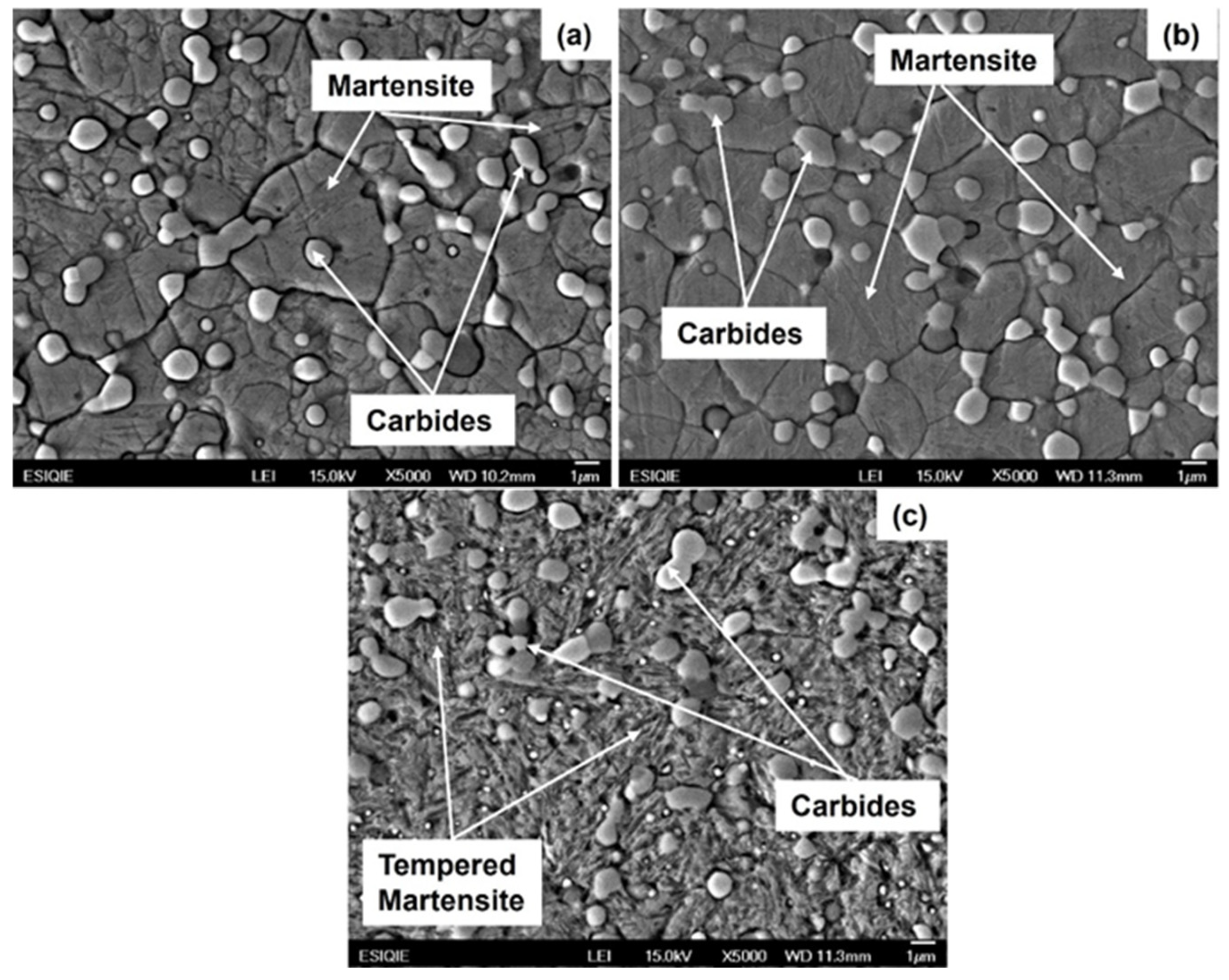
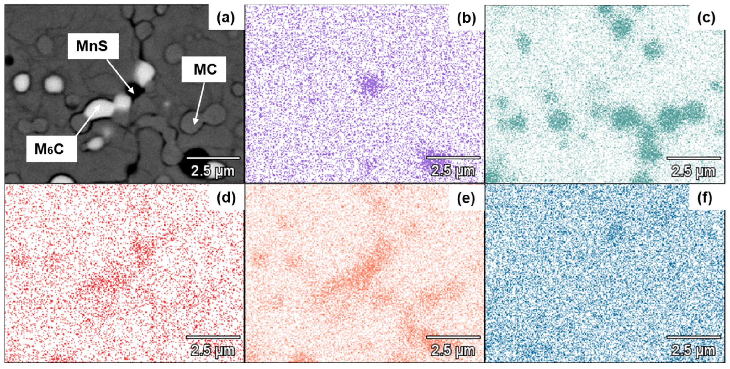
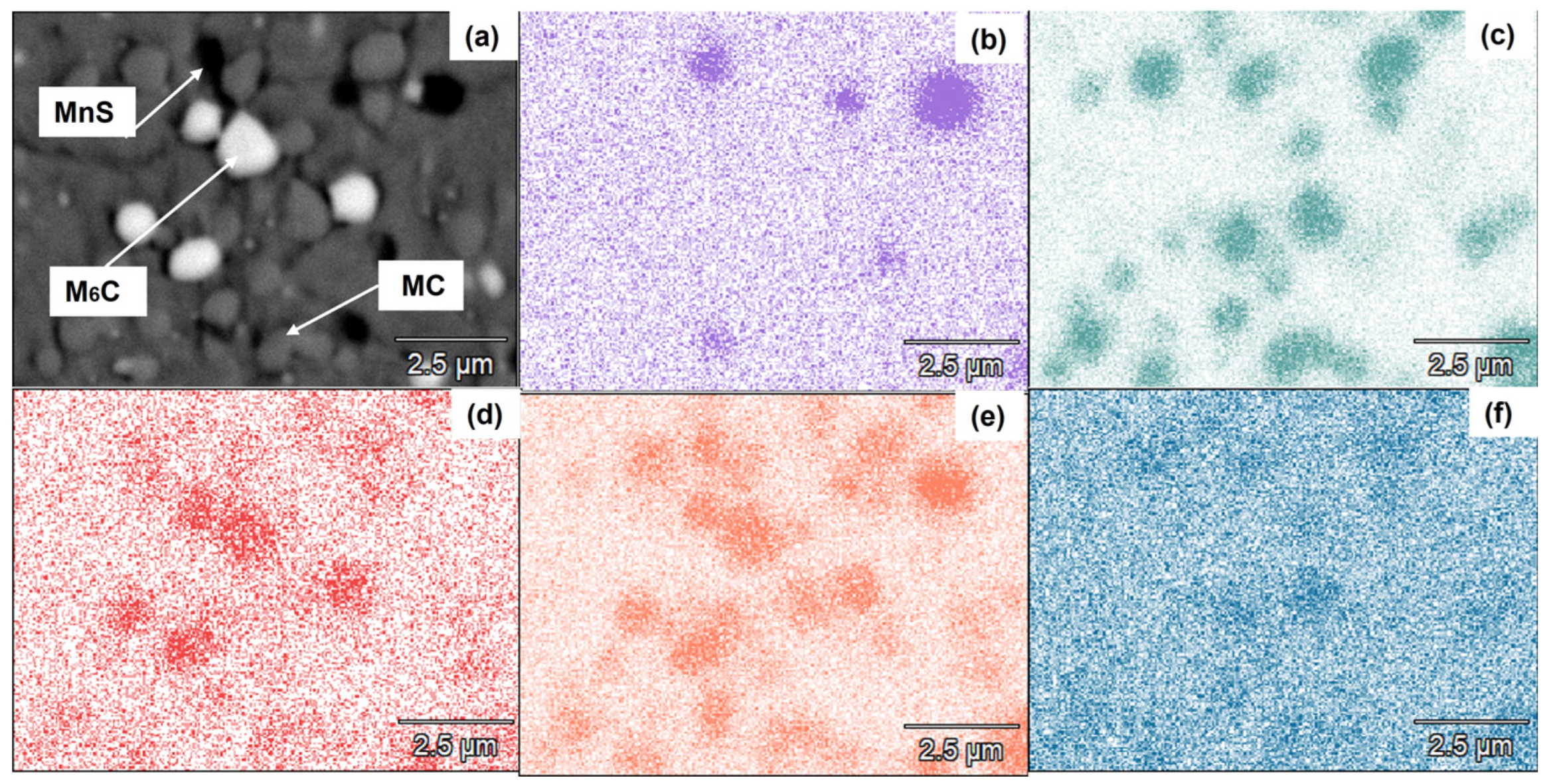
3.2. Microstructural Characterization of Heat-Treated Steel

Figure 6a–d show the OM micrographs of AISI M4 steel after annealing, air-cooling, quenching, and quenching-tempering treatments, respectively. The microconstituents in the annealed condition included intergranular and intragranular primary carbides dispersed in the ferritic matrix, as shown in Figure 6a. In contrast, both the air-cooled and quenched conditions presented a martensitic microconstituent with primary carbides present (Figure 6b,c). The quenched and tempered conditions resulted in tempered martensite with primary carbides and tempering-formed secondary carbides. OM observation of the polished specimen revealed a high volume fraction—about 0.02 (2 vol. %)—of MnS spheroid inclusions, which agrees well with the Thermo-Calc calculation, as expected due to the high S content.
The X-ray diffraction patterns of the annealed, air-cooled, quenched, and quenched–tempered steel specimens from this work are shown in Figure 7 and Figure 8a,b, respectively. In the case of the annealed specimen, the XRD peaks correspond to the ferrite, M6C, MC, and M23C6 carbides [22,23,28]. These phases are consistent with the Thermo-Calc predicted equilibrium phases at low temperatures (Figure 1). The XRD patterns for the air-cooled, quenched, and quenched–tempered specimens show diffraction peaks corresponding to martensite or tempered martensite, as well as M6C and MC carbides [22,23,24]. The XRD peaks corresponding to the MnS inclusions are present in all specimens. No retained austenite phase is present, as indicated by the XRD patterns. This finding is in good agreement with a high Ms of 340 °C, which suggests that no retained austenite forms during quenching.
SEM micrographs of the air-cooled, quenched, and quenched–tempered specimens are shown in Figure 9a–c, respectively. These micrographs show the presence of martensite plates alongside carbides.
Figure 10 and Figure 11a–f show the EDX–SEM elemental mappings of Mn, V, Cr, and Mo for the quenched and quenched–tempered specimens, respectively. Both figures indicate the presence of MnS inclusions as dark particles. The bright particles correspond to M6C carbides, where M is mainly W and Mo. In contrast, the gray particles are MC carbides, which are mainly composed of Cr. These results are consistent with those calculated by Thermo-Calc, as shown in the previous section. The primary carbides also have the beneficial effect of avoiding the growth of austenite grains during austenitizing. According to the literature [22], the hardness of MC carbides is higher than that of M6C carbides.

3.3. Rockwell Hardness of Heat-Treated Steels

Table 3 shows the HRC values for the samples subjected to different heat treatments. As expected, the highest hardness values, 65 and 63 HRC, correspond to the air-cooling and quenching treatments, respectively. This means that the cooling rates used in these treatments enabled us to obtain the martensite microconstituent. The softest condition, 24 HRC, corresponds to annealing, which produces the primary carbides MC, M23C6 and M6C dispersed in the ferritic matrix, as shown in Figure 7a.
On the other hand, the quenched–tempered specimen presented an HRC value of about 57. Tempering aims to increase martensite toughness and achieve secondary hardening due to the formation of fine carbides, mainly M6C carbides, at tempering temperatures of approximately 550 °C. An HRC of 57 is sufficient for fabricating shearing and cutting tools [1,4,5]. The austenitic grain size was approximately the same—5 μm—for both air-cooled and quenched specimens containing martensite. The martensite hardness shows no change with austenite grain size, as grain size influences only the plate length [28].

3.4. Relationship of Microstructure to Hardness

Figure 12 and Figure 13 present the results of quantitative metallography for the volume fraction and size of the different carbides in the normalized, quenched, and quenched–tempered specimens. These figures can be used to explain the differences in hardness among the heat-treated specimens. For instance, Figure 12 clearly shows that the total carbide and M6C volume fractions were higher for the tempered–quenched condition compared to the air-cooled and tempered conditions. Furthermore, the smallest carbide size was also observed in the tempered–quenched condition, as shown in Figure 13. This finding suggests that fine carbides were formed during the tempering process, which caused secondary hardening [29,30]. In contrast, the carbide volume fraction of the sample formed under the air-cooled condition is higher than that of the sample formed under the quenched condition, while the carbide size is lower for the former. This causes slightly higher hardness in the sample formed under the normalized condition. The carbide size is not comparable to that shown in Figure 3 because these results were determined at a constant temperature for intragranular precipitation, considering no previous formation of carbides. However, both intergranular and intergranular precipitation occurred during the steel-fabrication process, with more caused by heat treatment in this work.
Thermo-Calc-calculated results also indicate that the M6C and MC volume fractions were similar, at about 0.07 (7 vol. %). This value agrees well with the 7–8 vol. % shown in Figure 12 for the results of the various heat treatments used in the present work.
In general, the present work Thermo-Calc calculations are helpful for predicting phases and microconstituents during heat treatments applied to an AISI M4 steel, and thus for estimating hardness, as well as for designing heat treatments based on the calculated TTT diagram.

4. Conclusions

A phase-transformation study was conducted to analyze the heat treatments applied to a CPM AISI M4 steel, and the following conclusions were reached:
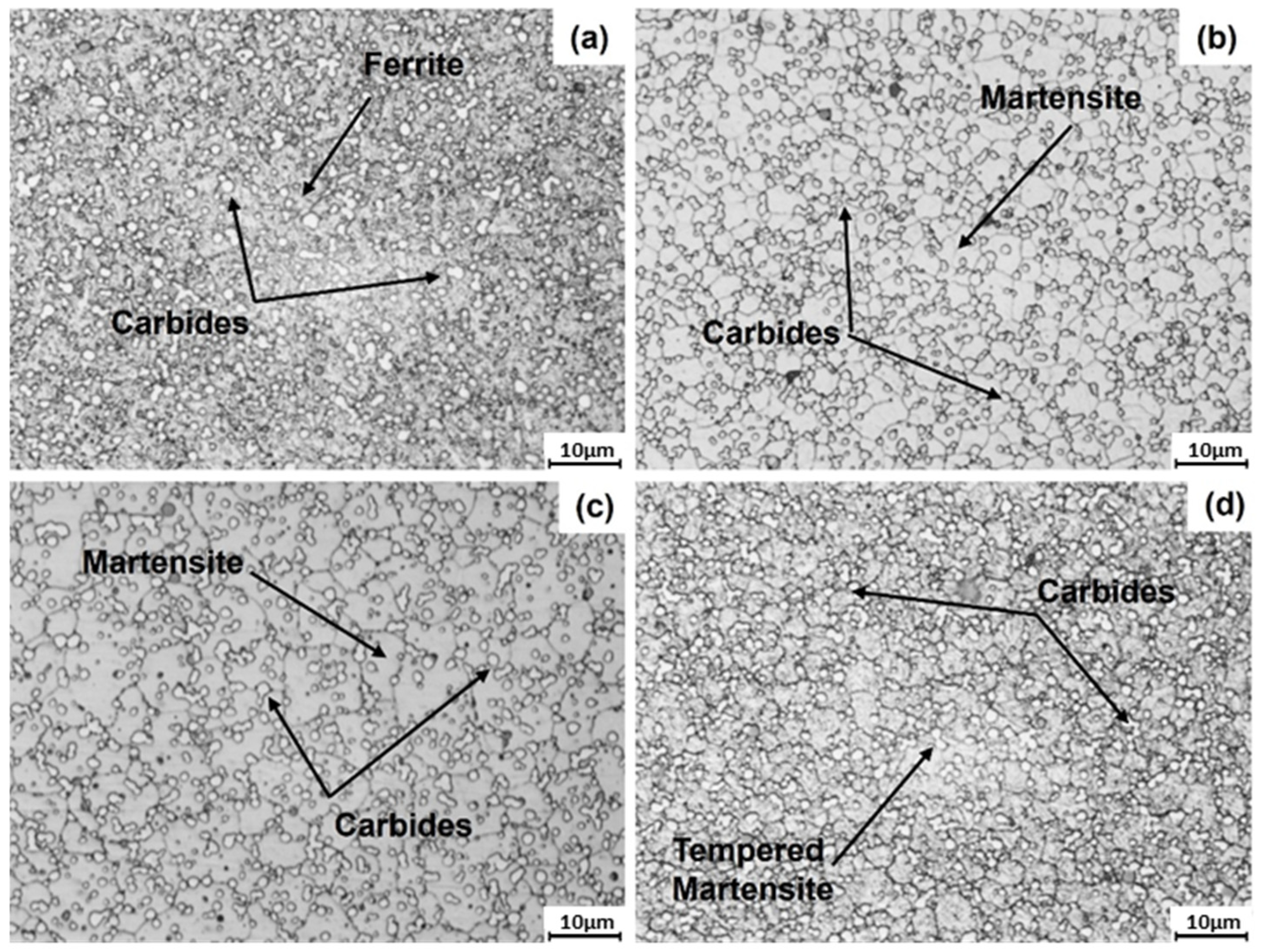
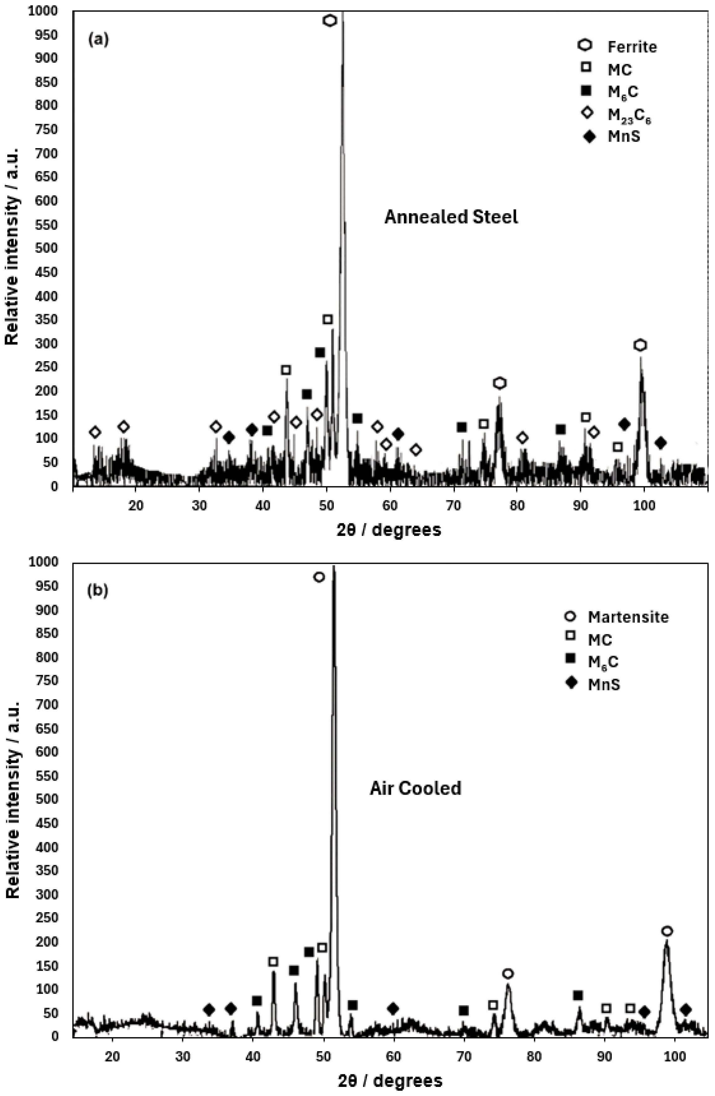
  • The ferrite and carbide phases observed in the annealed specimen are consistent with those predicted for the equilibrium condition using Thermo-Calc. The Rockwell C hardness measured for this heat treatment agrees with values expected for the observed phases.
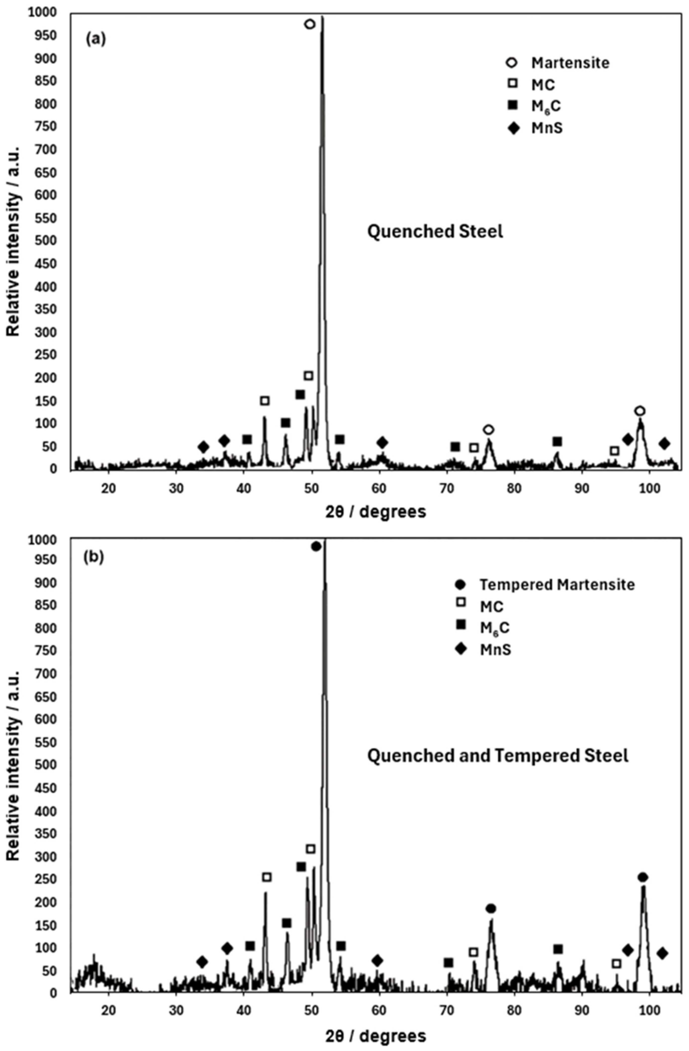
  • The martensite microconstituent obtained in the air-cooled and quenched conditions aligns well with that predicted by the nonequilibrium TTT diagram calculated using Thermo-Calc. The Rockwell C hardness is consistent with the observed microconstituent.
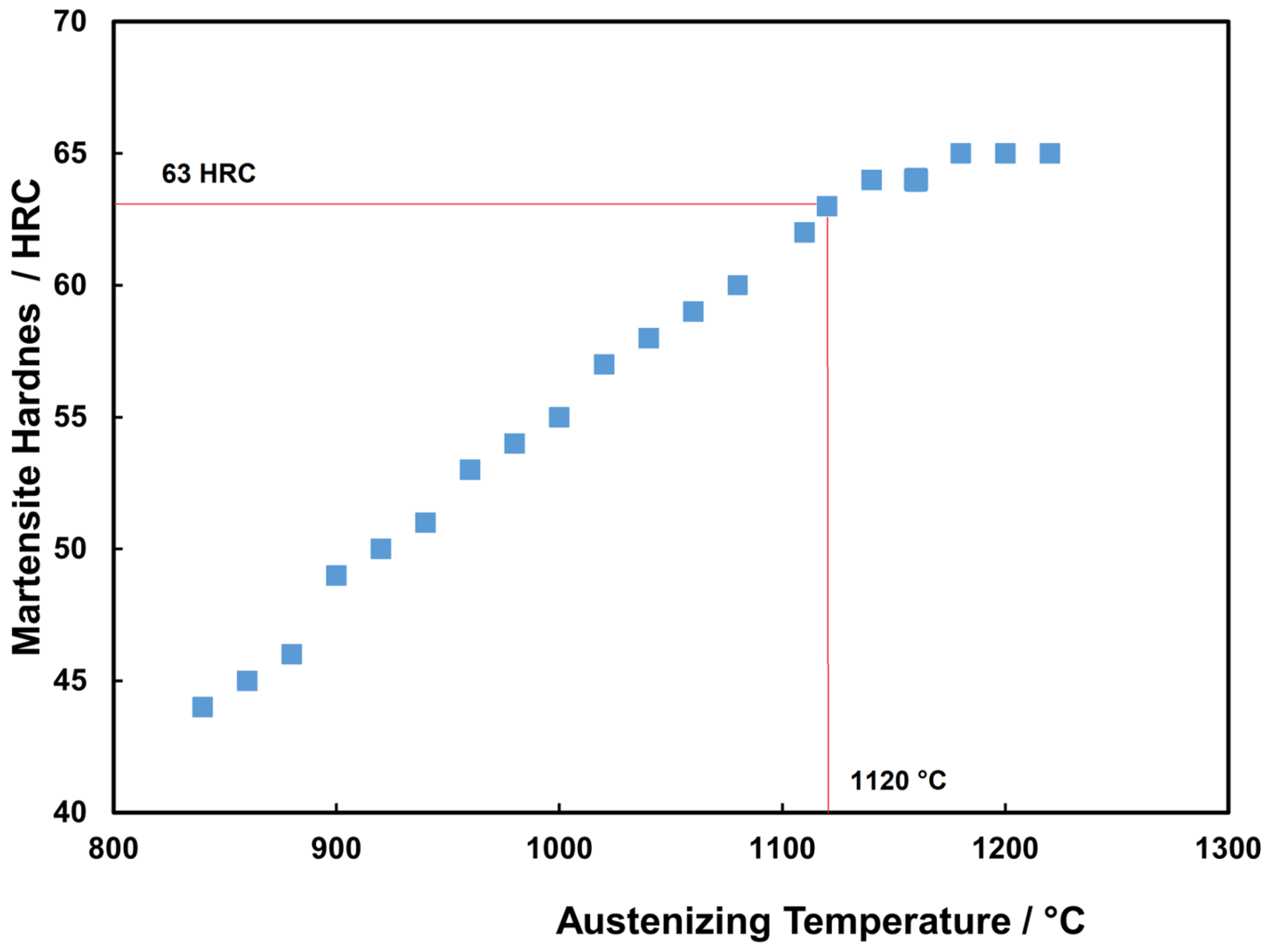
  • The austenitizing temperature and quenched hardness predicted using Themo-Calc show good agreement with the experimental values. This temperature enables the attainment of a suitable quenched Rockwell C hardness.
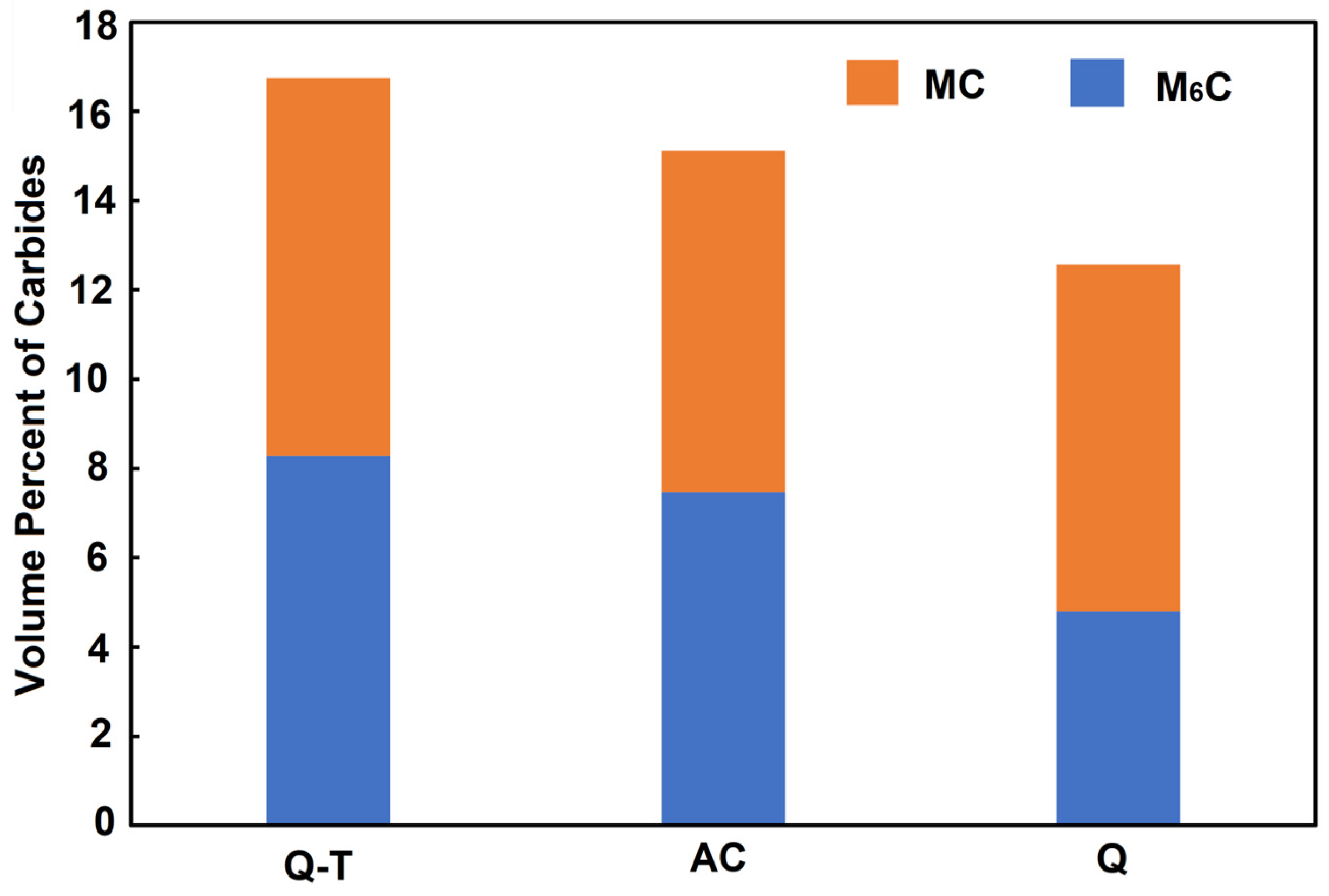
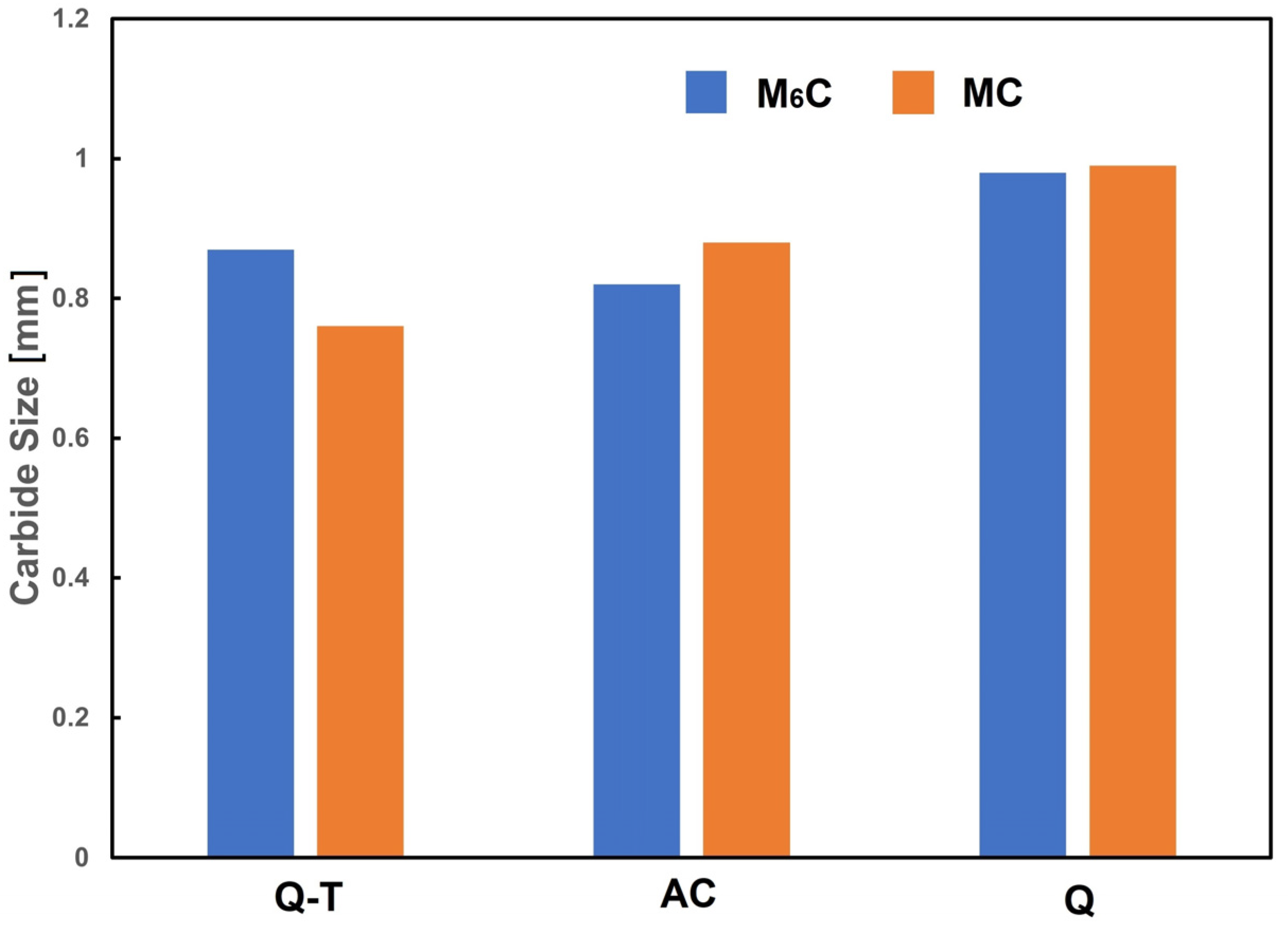
  • The tempering process led to an increase in the volume fraction of finer M6C carbides, promoting secondary hardening. This finding is beneficial for producing cutting tools with better performance.
  • The presence of Mo- and W-rich M6C carbides is essential if good mechanical properties are to be obtained in the quenched–tempered condition.

Author Contributions

Conceptualization, V.M.L.-H. and M.L.S.-M.; methodology, F.H.-S. and V.M.L.-H.; software, V.M.-L. and M.L.S.-M.; validation, V.M.-L. and V.M.L.-H.; formal analysis, C.F.-P. and V.M.L.-H.; investigation, F.H.-S. and M.L.S.-M.; resources, M.L.S.-M. and V.M.L.-H.; data curation, V.M.-L. and C.F.-P.; writing-original draft preparation, V.M.L.-H. and M.L.S.-M.; writing—review and editing, M.L.S.-M. and C.F.-P.; visualization, M.L.S.-M.; supervision V.M.L.-H.; project administration, M.L.S.-M. and V.M.L.-H.; funding acquisition, M.L.S.-M. and V.M.L.-H. All authors have read and agreed to the published version of the manuscript.

Funding

This research was funded by financial support from IPN-SIP 2025-Beifi.

Data Availability Statement

The raw data supporting the conclusions of this article will be made available by the authors on request.

Conflicts of Interest

The authors declare no conflicts of interest.

References

  1. Bryson, W.E. Heat Treatment Selection, and Application of Tool Steels, 2nd ed.; Carl Hanser Verlag GmbH & Co. KG: Munich, Germany, 2005; pp. 75–82. [Google Scholar]
  2. Moon, H.K.; Lee, K.B. Influences of Co addition and austenitizing temperature on secondary hardening and impact fracture behavior in P/M high speed steels of W–Mo–Cr–V(–Co) system. Mater. Sci. Eng. 2008, 474, 328–334. [Google Scholar] [CrossRef]
  3. Chaus, A.S.; Kryshtal, A.P. New insights into the microstructure of M2 high-speed steel. Mater. Charact. 2023, 205, 113313. [Google Scholar] [CrossRef]
  4. Kraus, R.G.; Kennedy, R. Tool Steels, 5th ed.; ASM: Novelty, OH, USA, 1998; pp. 46–123. [Google Scholar]
  5. Jurci, P.; Dlouhy, I. Tratamiento criogénico de aceros martensíticos: Fundamentos microestructurales e implicaciones para las propiedades mecánicas y el rendimiento frente al desgaste y la corrosión. Materials 2024, 17, 548. [Google Scholar] [PubMed]
  6. Shim, D.-S.; Baek, G.-Y.; Lee, S.-B.; Yu, J.H.; Choi, Y.-S.; Park, S.-H. Influence of heat treatment on wear behavior and impact toughness of AISI M4 coated by laser melting deposition. Surf. Coat. Technol. 2017, 328, 219–230. [Google Scholar] [CrossRef]
  7. Damon, J.; Schüßler, P.; Mühl, F.; Dietrich, S.; Schulz, V. Short-time induction heat treatment of high-speed steel AISI M2: Laboratory proof of and application-related component tests. Mater. Des. 2023, 230, 111991. [Google Scholar] [CrossRef]
  8. Fu, H.; Qu, Y.; Xing, J.; Zhi, X.; Jiang, Z.; Li, M.; Zhang, Y. Investigations on heat treatment of a high-speed steel roll. JMEPEG. 2008, 17, 535–542. [Google Scholar] [CrossRef]
  9. Baek, G.-Y.; Shin, G.-Y.; Lee, K.-Y.; Shim, D.-S. Effect of post-heat treatment on the AISI M4 layer deposited by directed energy deposition. Metals 2020, 10, 703. [Google Scholar] [CrossRef]
  10. Jardin, R.T.; Turninetti, V.; Tchuinjang, J.T.; Duchene, L.; Hashemi, N.; Tran, H.S.; Carrus, R.; Martens, A.; Habraken, A.M. Optimizing laser power directed energy by deposition process for homogeneous AISI M4 steel microstructure. Opt. Laser Technol. 2023, 163, 109426. [Google Scholar] [CrossRef]
  11. Hu, Q.; Wang, M.; Chen, Y.; Li, H.; Si, Z. The effect of MC-type carbides on the microstructure and wear behavior of S390 high-speed steel produced via spark plasma sintering. Metals 2022, 12, 2168. [Google Scholar] [CrossRef]
  12. Shi, P.; Engstrom, A.; Hoglund, L.; Sundman, B.; Agren, J. Thermo-Calc and DICTRA enhance Materials Design and Process. Mater. Sci. For. 2005, 475–479, 3339–3346. [Google Scholar]
  13. Briki, J.; Slima, S.B. A new continuous cooling transformation diagram for AISI M4 high-speed tool steel. J. Mater. Eng. Perform. 2008, 17, 864–869. [Google Scholar] [CrossRef]
  14. Luo, Y.; Guo, H.; Sun, X.; Mao, M.; Guo, J. Effects of austenitizing conditions on the microstructure of AISI M42 high-speed steel. Metals 2017, 7, 27. [Google Scholar] [CrossRef]
  15. Lopez-Hirata, V.M.; Hernandez-Santiago, F.; Saucedo-Muñoz, M.L.; Dorantes-Rosales, H.J.; Paniagua-Mercado, A.M. Growth kinetics of β’precipitation in a ferritic matrix during isothermal aging of Cu-containing Fe-10at.%Ni-15at.%Al alloys. Mater. Res. 2018, 21, 1–7. [Google Scholar]
  16. Thermo-Calc. Thermo-Calc, versión 2024b; PRISMA: Stockholm, Sweden, 2024.
  17. Cheng, O.; Wu, K.; Sterner, G.; Mason, P. Modeling Precipitation Kinetics During Heat Treatment with Calphad-Based Tools. J. Mater. Eng. Perform. 2014, 23, 4193–4196. [Google Scholar] [CrossRef]
  18. Yang, J.-Y.; Agren, J.; Jeppsson, J. Pearlite in multicomponent steels: Phenomenological steady-state modeling. Met. Mater. Trans. 2020, 51A, 1978–2001. [Google Scholar]
  19. Leach, L.; Kolmskog, P.; Höglund, L.; Hillert, M.; Borgenstam, A. Critical driving forces for formation of bainite. Met. Mater. Trans. 2018, 49A, 4509–4518. [Google Scholar] [CrossRef]
  20. Huyan, M.; Hedstrom, M.; Höglund, L.; Borgenstam, A. A thermodynamic-based model to predict the fraction of martensite in steels. Met. Mater. Trans. 2016, 47A, 4404–4410. [Google Scholar] [CrossRef]
  21. ASTM E18-22; Standard Test Methods for Rockwell Hardness of Metallic Materials. ASTM: West Conshohocken, PA, USA, 2022.
  22. Zhou, X.; Xu, X.Z.; Shen, Y.; Shi, T.; Huang, X. Identification of precipitate phases in an 11%Cr ferritic/martensitic steel after short-term creep. ISIJ Int. 2018, 58, 1467. [Google Scholar] [CrossRef]
  23. Wang, L.N.; Sun, X.F.; Guan, H.R. Effect of Melt Heat Treatment on MC Formation in Nickel Base Superalloy. Results Phys. 2017, 7, 2111–2117. [Google Scholar] [CrossRef]
  24. Ma, S.; Xing, J.; He, Y.; Li, Y. Microstructure and crystallography of M7C3 carbide in chromium cast iron. Mater. Chem. Phys. 2015, 161, 65–73. [Google Scholar] [CrossRef]
  25. Bowman, A.L.; Arnold, G.P.; Storms, E.; Nereson, N.G. The crystal structure of Cr23C6. Struct. Sci. 1972, 28, 3102–3103. [Google Scholar] [CrossRef]
  26. Porter, D.A.; Easterling, K.E.; Sherif, M.Y. Phase Transformations in Metals and Alloys, 4th ed.; CRC: Boca Raton, FL, USA, 2022; pp. 451–468. [Google Scholar]
  27. ASTM 255-20A; Standard Test Methods for Determining Hardenability of Steel. ASTM: West Conshohocken, PA, USA, 2022.
  28. Kraus, G. Steels: Processing, Structure, and Performance, 2nd ed.; ASM: Novelty, Ohio, USA, 2015; pp. 621–642. [Google Scholar]
  29. Kostorz, G. Phase Transformations in Materials, 2nd ed.; Wiley-VCH: Weinheim, Germany, 2001; pp. 309–408. [Google Scholar]
  30. Brooks, C.R. Heat Treatments of Ferrous Alloys, 1st ed.; Mc Graw-Hill: New York, NY, USA, 1979; pp. 149–177. [Google Scholar]
Figure 1. TC-calculated plot of volume fraction of equilibrium phases against temperature for the AISI M4 steel.
Metals 15 00818 g001
Figure 2. Thermo-Calc-calculated TTP diagram for the AISI M4 steel.
Metals 15 00818 g002
Figure 3. Thermo-Calc-calculated plot of precipitate mean radius vs. time at 1120 °C.
Metals 15 00818 g003
Figure 4. TC-calculated TTT diagram for the AISI M4 steel at 1120 °C.
Metals 15 00818 g004
Figure 5. Expected HRC values of martensite versus austenitizing temperature.
Metals 15 00818 g005
Figure 6. OM micrographs for the (a) annealed, (b) air-cooled, (c) quenched, and (d) quenched–tempered AISI M4 steel specimens.
Metals 15 00818 g006
Figure 7. XRD patterns for (a) annealed and (b) normalized AISI M4 steel specimens in the present work.
Metals 15 00818 g007
Figure 8. XRD patterns for (a) quenched and (b) quenched–tempered AISI M4 steel specimens in the present work.
Metals 15 00818 g008
Figure 9. SEM micrographs for the (a) air-cooled, (b) quenched, and (c) quenched–tempered AISI M4 steel specimens.
Metals 15 00818 g009
Figure 10. (a) SEM image and element mapping of (b) Mn, (c) V, (d) W, (e) Mo, and (f) Cr for the quenched AISI M4 steel specimen.
Metals 15 00818 g010
Figure 11. (a) SEM image and element mapping of (b) Mn, (c) V, (d) W, (e) Mo, and (f) Cr for the quenched–tempered AISI M4 steel specimen.
Metals 15 00818 g011
Figure 12. Carbide volume fraction for the various heat treatments applied to AISI M4 steel.
Metals 15 00818 g012
Figure 13. Carbide size for the various heat treatments applied to AISI M4 steel.
Metals 15 00818 g013
Table 1. Actual chemical composition of CPM AISI M4 steel.
ElementFeCMnSiCr
wt. %Bal.1.470.570.304.42
ElementMoVWSP
wt. %5.414.055.590.220.01
Table 2. TC-calculated chemical composition in wt. % for austenite at different temperatures.
Temperature (°C)CMnSiCrMoVW
9000.170.280.344.361.270.270.0
10000.260.290.334.402.040.520.0
11200.410.300.324.403.041.050.0
Table 3. HRC values for the heat-treated steel specimens.
Heat TreatmentHRC
Annealing24 ± 2
Air-Cooling65 ± 2
Quenching63 ± 2
Quenching and Tempering57 ± 2
Disclaimer/Publisher’s Note: The statements, opinions and data contained in all publications are solely those of the individual author(s) and contributor(s) and not of MDPI and/or the editor(s). MDPI and/or the editor(s) disclaim responsibility for any injury to people or property resulting from any ideas, methods, instructions or products referred to in the content.

