
Response and Failure Behavior of Square Tubes with Varying Outer Side Lengths Under Cyclic Bending in Different Directions


Abstract
1. Introduction
2. Materials and Methods
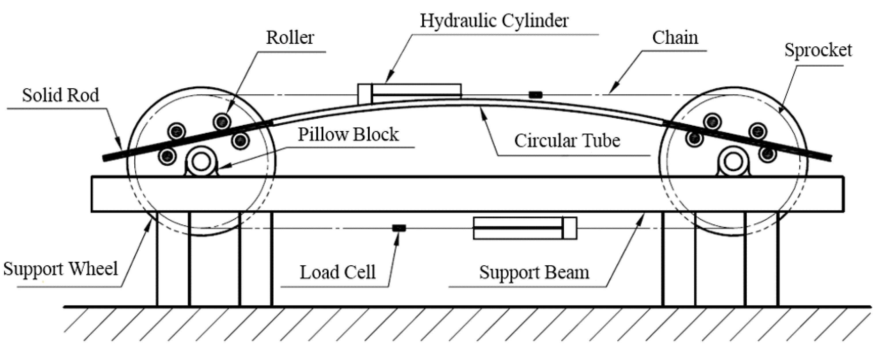
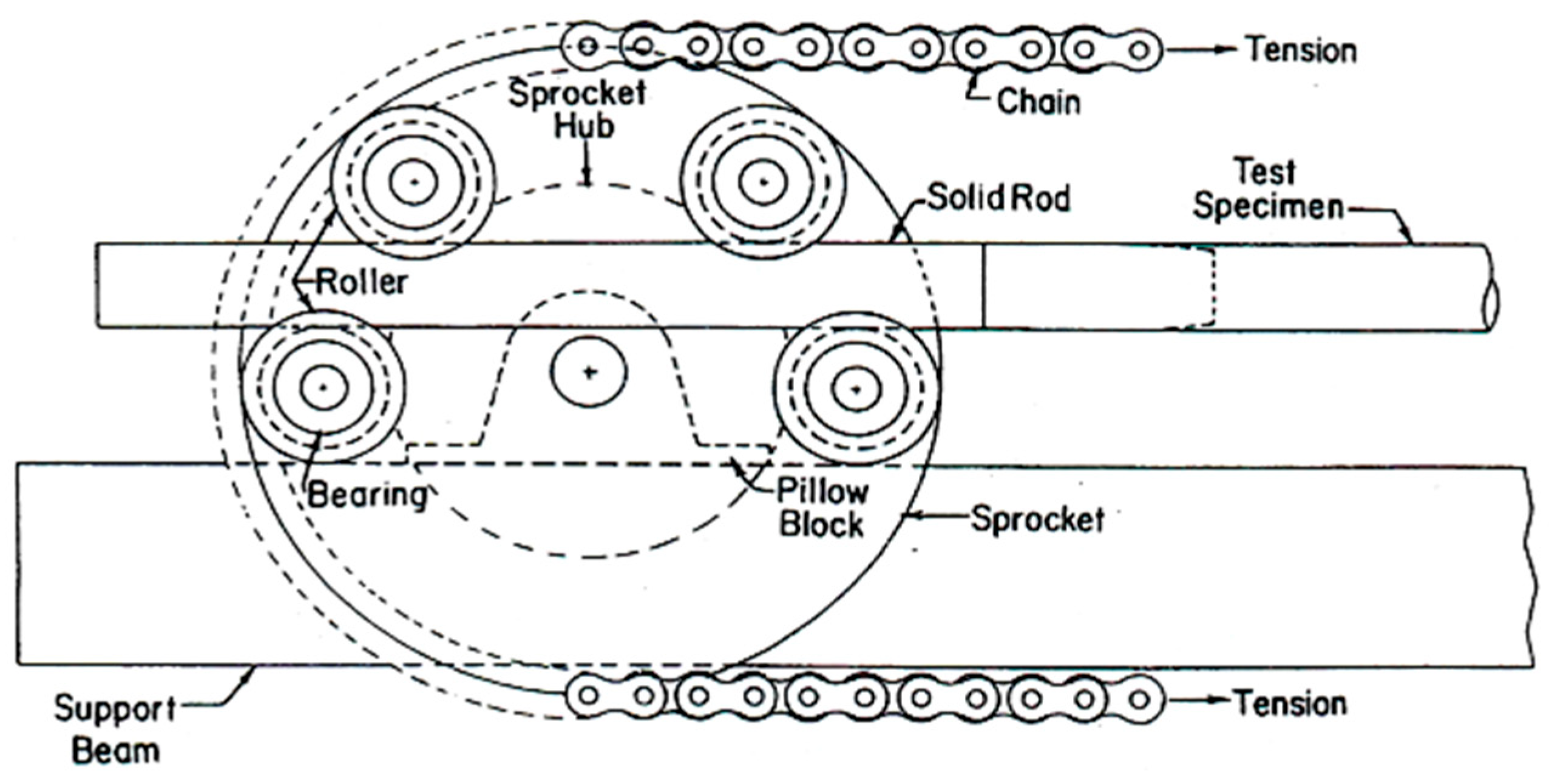
2.1. Bending Device
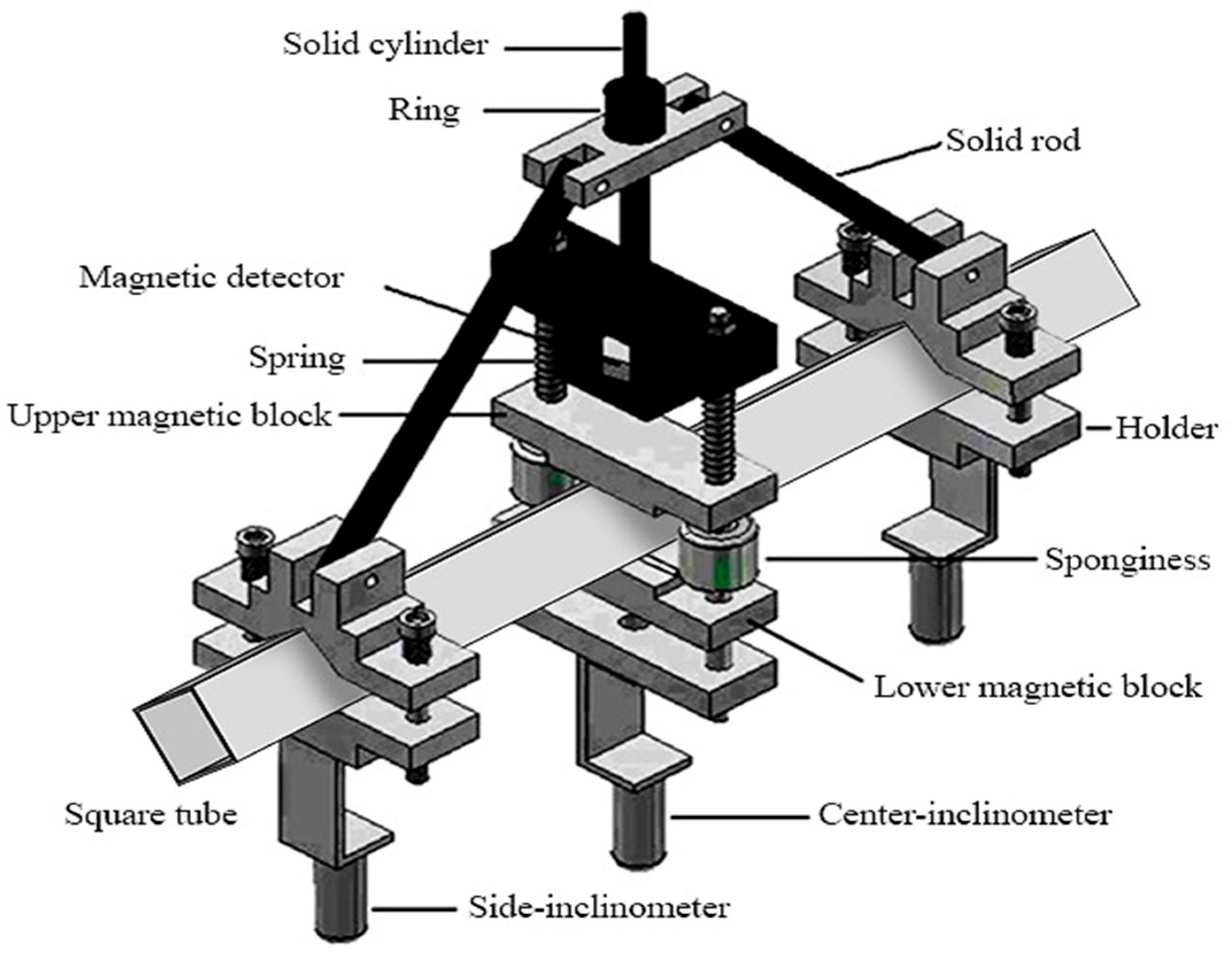
2.2. Curvature–Ovalization Measurement Apparatus (COMA)
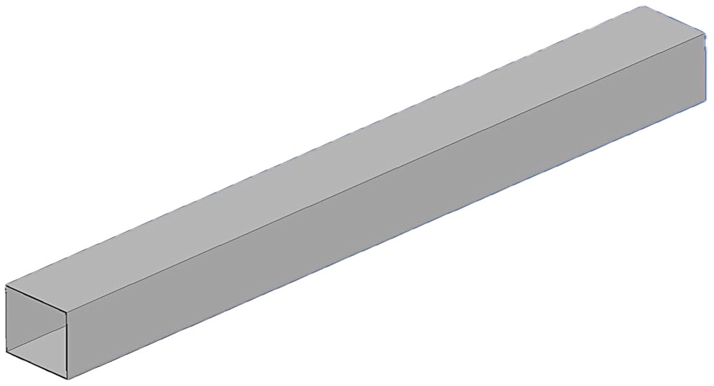
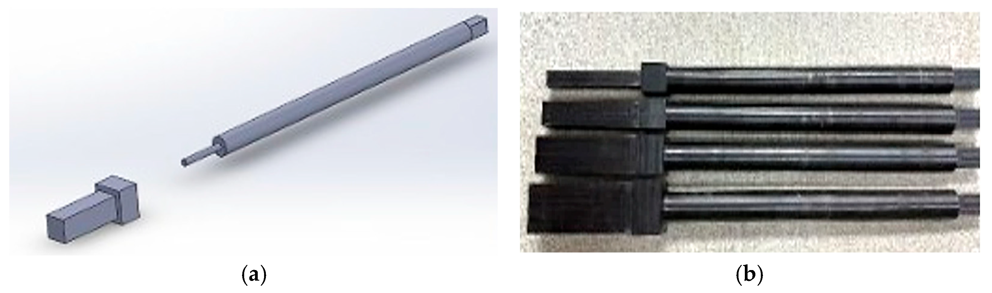
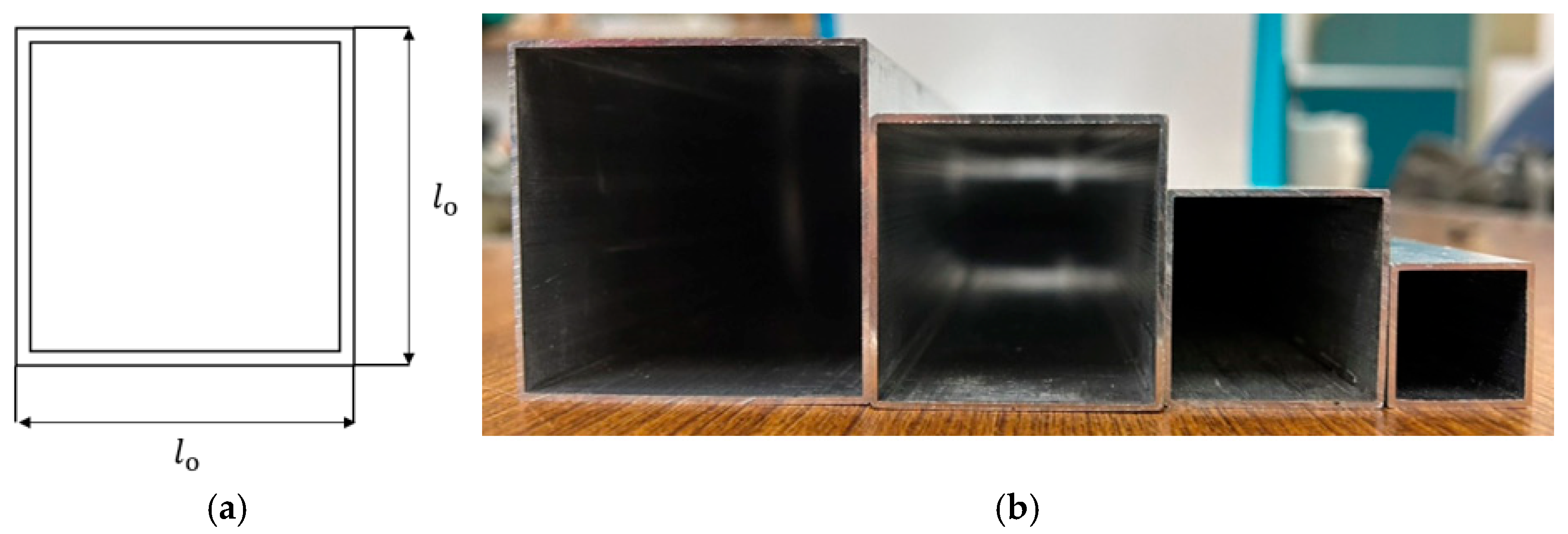
2.3. Square Tubes
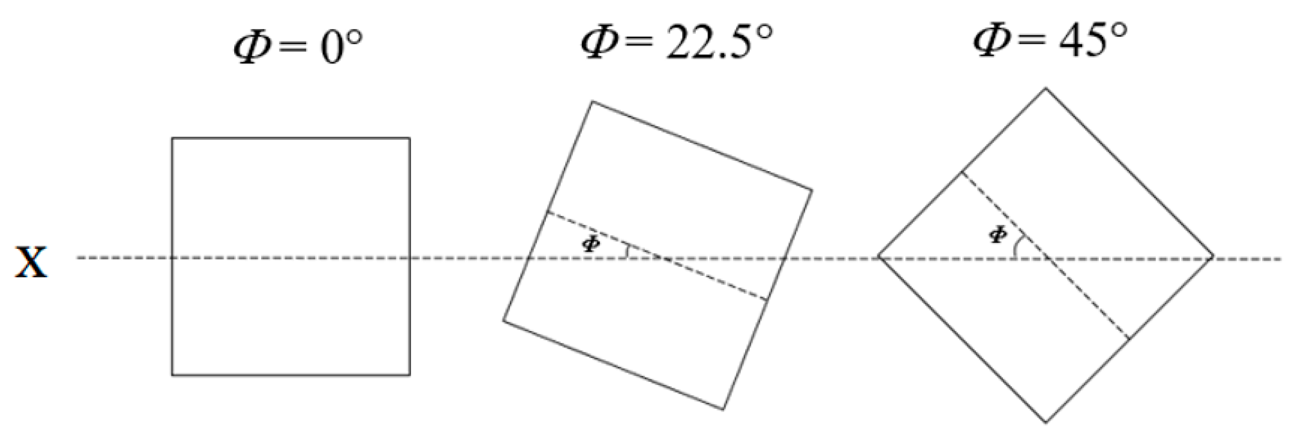
2.4. Test Procedures
3. Results and Discussion
3.1. Appearance Changes of Square Tubes
3.2. Relationship Between the Moment (M) and Curvature (κ)
3.3. Relationship Between Outer Side Length Variation (Δℓ/ℓo) and Curvature (κ)
3.4. Relationship Between the Curvature (κ) and Number of Cycles Required to Initiate Buckling (Nb)

4. Conclusions
- (1)
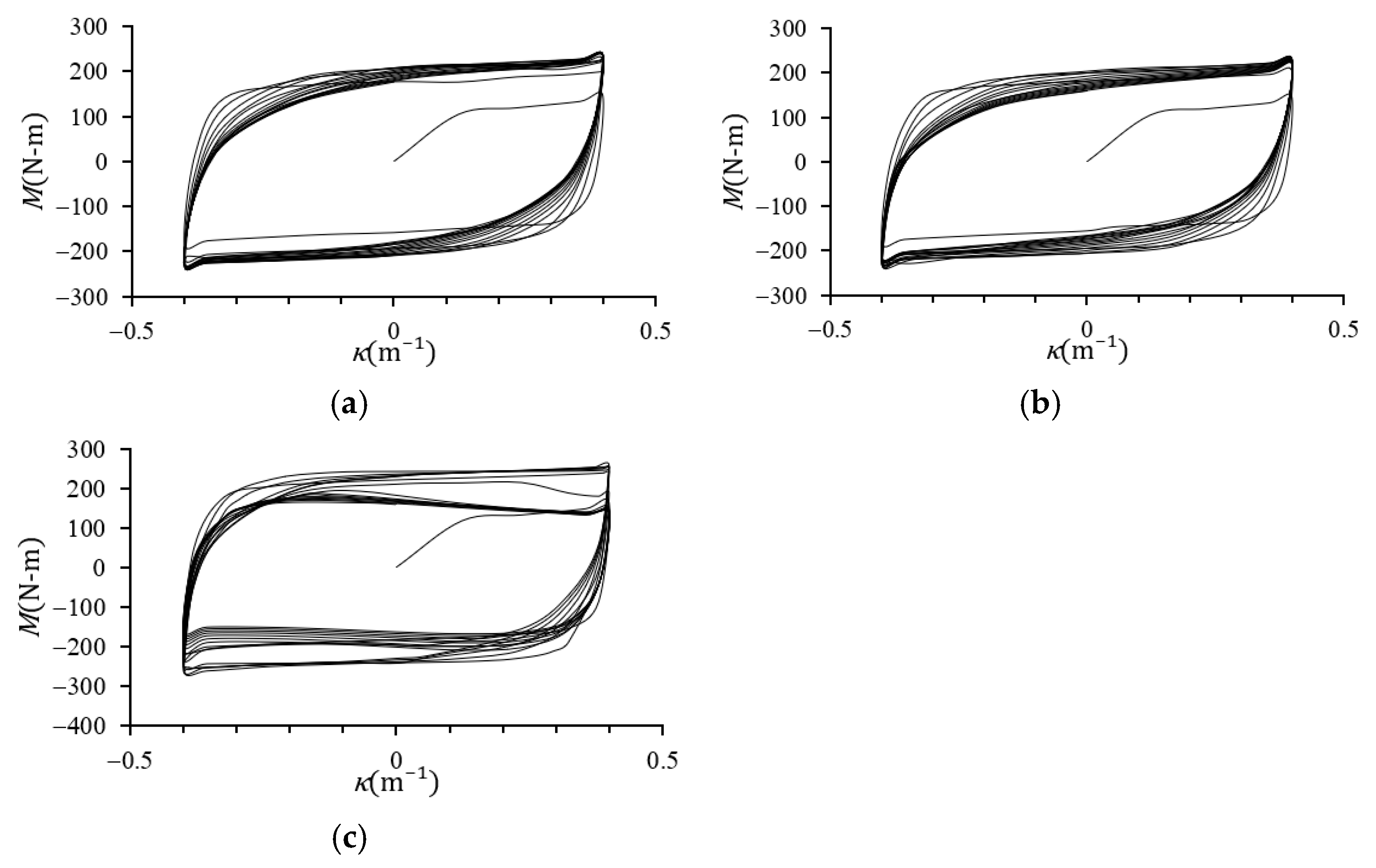
- During the initial loading stage, the square tubes exhibited elastic behavior, resulting in a linear increase in bending moment (M) with increasing curvature (κ). As κ increased further, plastic deformation initiated, causing the M–κ curves to gradually flatten and permanent deformation to occur. All M–κ curves demonstrated cyclic hardening and stabilized after several loading cycles. At a fixed bending angle (Φ), increasing ℓo led to a higher peak M value. Similarly, for a fixed ℓo, increasing Φ resulted in a gradual increase in the peak M value.
- (2)
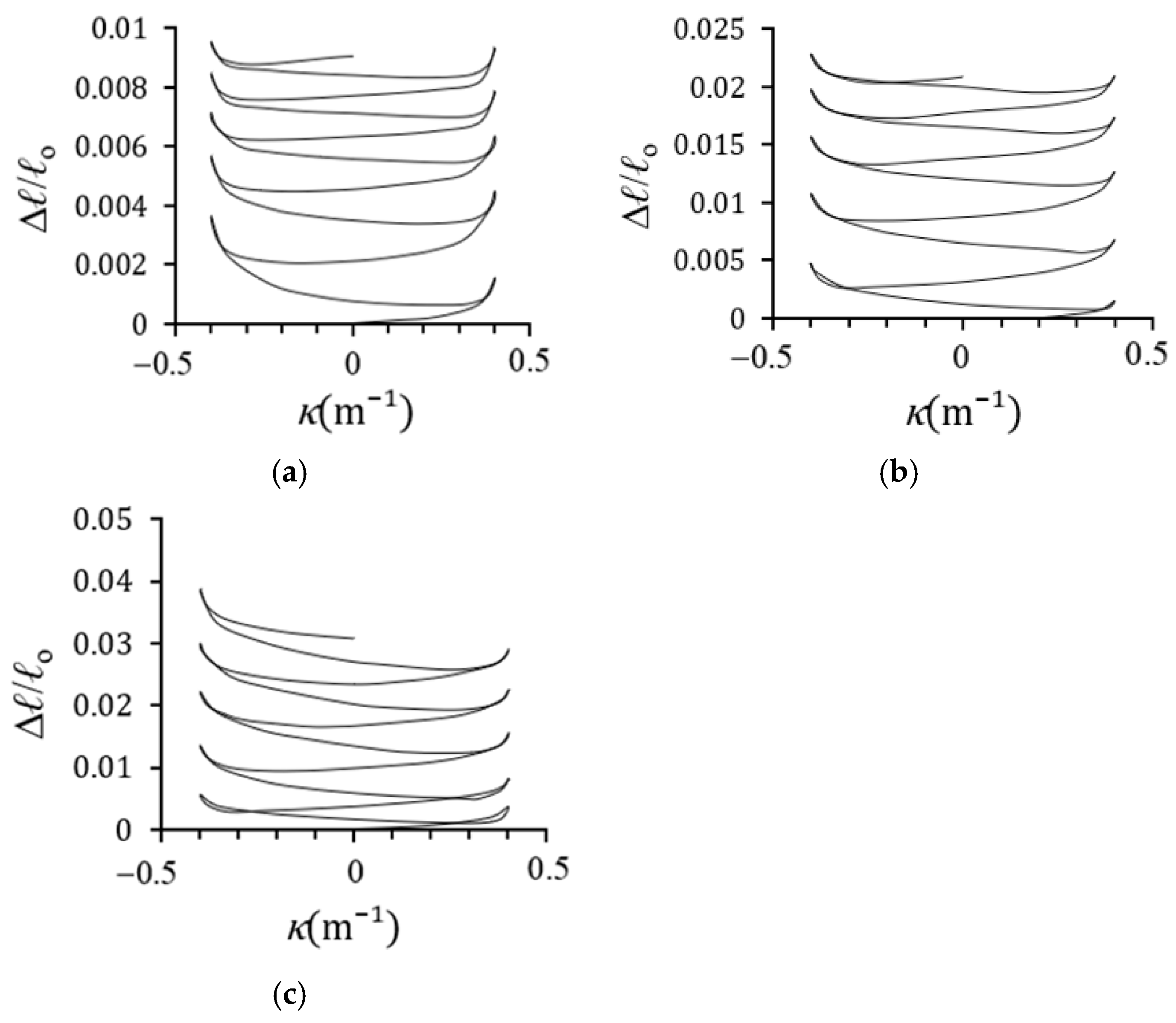
- The Δℓ/ℓo-κ curves exhibited nonlinear behavior, regardless of whether the square tube underwent elastic or plastic bending deformation. As the number of cyclic bending loads increased, Δℓ/ℓo continued to grow. For a fixed Φ, the Δℓ/ℓo-κ curves displayed symmetry, serrated patterns, and progressive growth with increasing cycle count. At a fixed κ, increasing ℓo or Φ led to an increase in Δℓ/ℓo.
- (3)
- The Δℓ/ℓo-κ curves exhibited nonlinear behavior regardless of whether the square tubes experienced elastic or plastic bending deformation. With increasing numbers of cyclic bending loads, Δℓ/ℓo progressively increased. For a fixed bending angle (Φ), the Δℓ/ℓo-κ curves demonstrated symmetry, serrated patterns, and incremental growth as the cycle count increased. At a constant curvature (κ), increasing either ℓo or Φ resulted in higher Δℓ/ℓo values.
- (4)
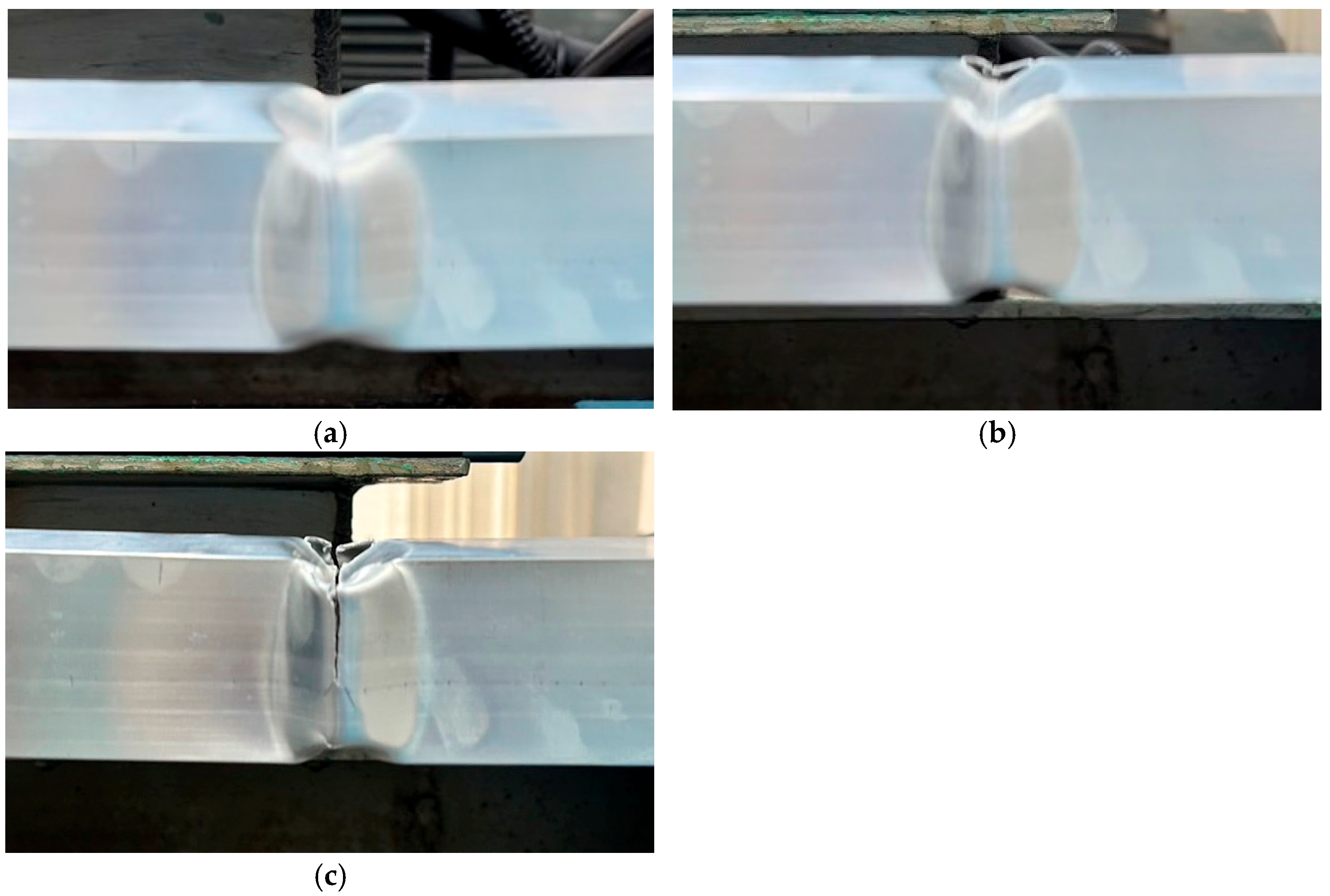
- The deformation process of square tubes under cyclic bending can be categorized into four distinct stages based on their external appearance: the initial, second, third, and fourth stages. The transition from the first to the second stage is marked by a decrease in bending moment of approximately 20%, which is used as the buckling criterion in this study.
- (5)
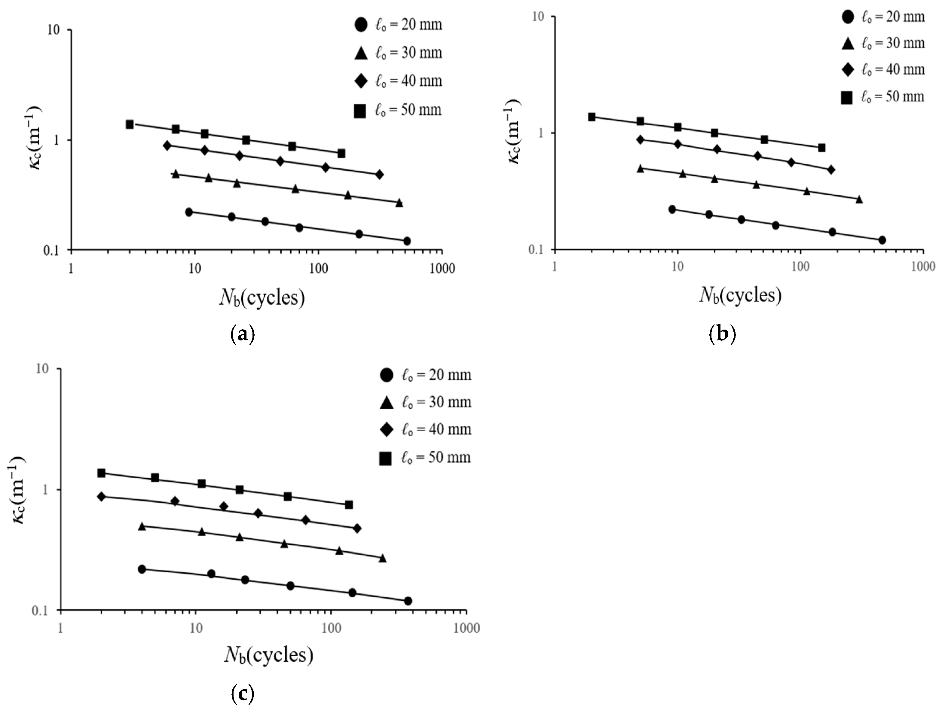
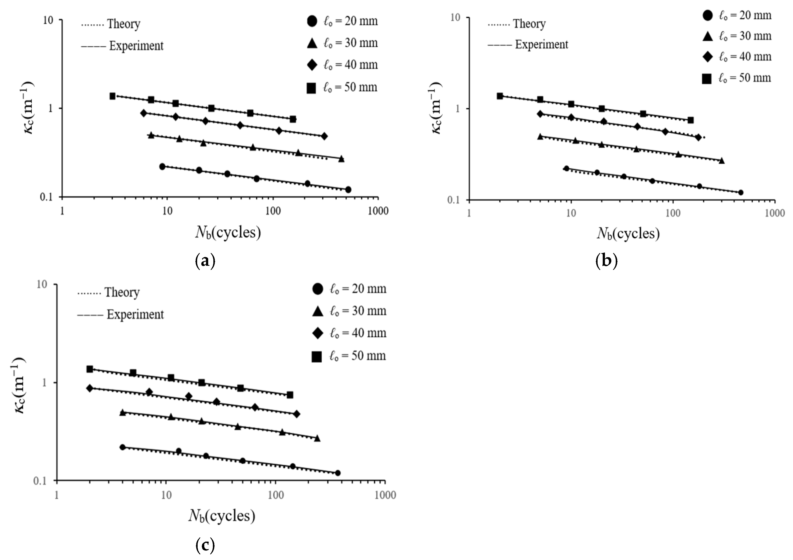
- The κc–Nb relationships indicated that, at a fixed Φ and ℓo, Nb decreased with increasing κc. Similarly, at a fixed Φ and κc, Nb increased as ℓo increased. For a fixed ℓo and κc, Nb slightly decreased with increasing Φ. When the κc–Nb data were plotted on double logarithmic coordinates, the four distinct ℓo values corresponded to four straight lines for each Φ, each with a unique slope and intercept.
- (6)
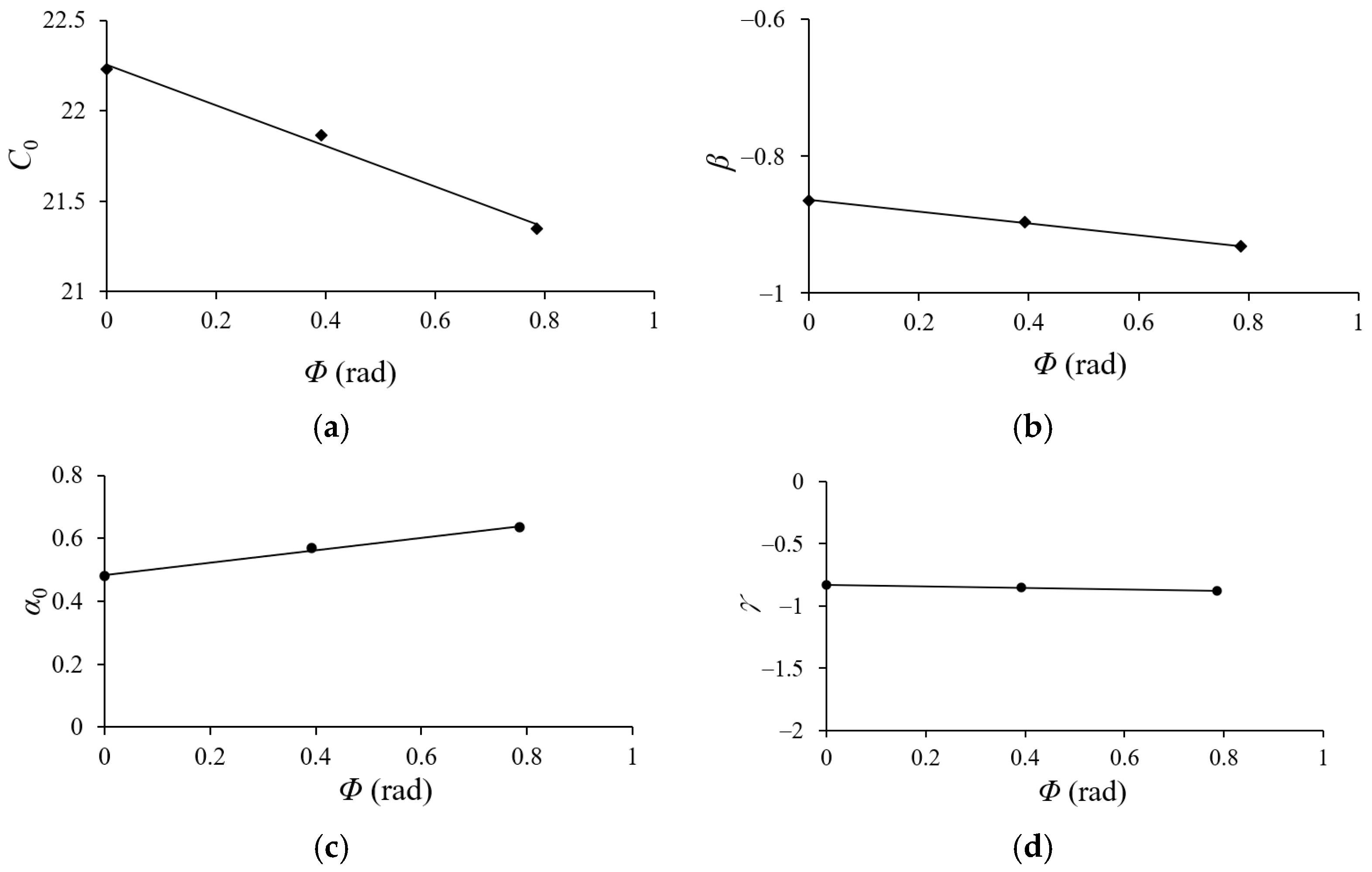
- Equations (1) or (2) can be used to describe the κc–Nb relationships. Experimental data revealed linear relationships between logC and ℓo/t (Figure 16a) and between logα and ℓo/t (Figure 16b), which were used to derive Equations (3) and (4), respectively. Additionally, the data in Figure 16a,b were employed to establish linear relationships between Co and Φ (Figure 17a), β and Φ (Figure 17b), αo and Φ (Figure 17c), and γ and Φ (Figure 17d), leading to Equations (5)–(8). These equations were then used to predict the κc–Nb behavior of 6063-T6 aluminum alloy square tubes under cyclic bending with various ℓo and Φ values. As illustrated in Figure 18a–c, the predicted results aligned well with the experimental data, indicating that the proposed equations effectively represent the observed behavior.
Author Contributions
Funding
Data Availability Statement
Conflicts of Interest
References
- Jin, S.Y.; Altenhof, W. Comparison of the load/displacement and energy absorption performance of round and square AA6061-T6 extrusions under a cutting deformation mode. Int. J. Crashworthiness 2007, 12, 265–278. [Google Scholar] [CrossRef]
- Hanssen, A.G.; Langseth, M.; Hopperstad, O.S. Static and dynamic crushing of circular aluminum extrusions with aluminum foam filler. Int. J. Impact Eng. 2000, 24, 475–507. [Google Scholar] [CrossRef]
- Kyriakides, S.; Shaw, P.K. Inelastic buckling of tubes under cyclic bending. J. Press. Vessel Technol. 1987, 109, 169–178. [Google Scholar] [CrossRef]
- Corona, E.; Kyriakides, S. An experimental investigation of the degradation and buckling of circular tubes under cyclic bending and external pressure. Thin-Walled Struct. 1991, 12, 229–263. [Google Scholar] [CrossRef]
- Corona, E.; Kyriakides, S. Asymmetric collapse modes of pipes under combined bending and pressure. Int. J. Solids Struct. 2000, 24, 505–535. [Google Scholar] [CrossRef]
- Corona, E.; Lee, L.H.; Kyriakides, S. Yield anisotropic effects on buckling of circular tubes under bending. Int. J. Solids Struct. 2006, 43, 7099–7118. [Google Scholar] [CrossRef]
- Limam, A.; Lee, L.H.; Corana, E. Inelastic wrinkling and collapse of tubes under combined bending and internal pressure. Int. J. Mech. Sci. 2010, 52, 37–47. [Google Scholar] [CrossRef]
- Limam, A.; Lee, L.H.; Corona, E.; Kyriakides, S. On the collapse of dented tubes under combined bending and internal pressure. Int. J. Solids Struct. 2012, 55, 1–12. [Google Scholar] [CrossRef]
- Bechle, N.J.; Kyriakides, S. Localization of NiTi tubes under bending. Int. J. Solids Struct. 2014, 51, 967–980. [Google Scholar] [CrossRef]
- Jiang, D.; Kyriakides, S.; Bechle, N.J.; Landis, C.M. Bending of pseudoelastic NiTi tubes. Int. J. Solids Struct. 2017, 124, 192–214. [Google Scholar] [CrossRef]
- Kazinakis, K.; Kyriakides, S.; Jiang, D.; Bechle, N.J.; Landis, C.M. Buckling and collapse of pseudoelastic NiTi tubes under bending. Int. J. Solids Struct. 2021, 221, 2–17. [Google Scholar] [CrossRef]
- Yuan, W.; Mirmiran, A. Buckling analysis of concrete-filled FRP tubes. Int. J. Struct. Stab. Dyn. 2001, 1, 367–383. [Google Scholar] [CrossRef]
- Elchalakani, M.; Zhao, X.L.; Grzebieta, R.H. Plastic mechanism analysis of circular tubes under pure bending. Int. J. Mech. Sci. 2002, 44, 1117–1143. [Google Scholar] [CrossRef]
- Houliara, S.; Karamanos, S.A. Buckling and post-buckling of long pressurized elastic thin-walled tubes under in-plane bending. Int. J. Nonlinear Mech. 2006, 44, 491–511. [Google Scholar] [CrossRef]
- Yazdani, H.; Nayebi, A. Continuum damage mechanics analysis of thin-walled tube under cyclic bending and internal constant pressure. Int. J. Appl. Mech. 2013, 5, 1350038. [Google Scholar] [CrossRef]
- Elchalakani, M.; Karrech, A.; Hassanein, M.F.; Yang, B. Plastic and yield slenderness limits for circular concrete filled tubes subjected to static pure bending. Thin-Walled Struct. 2016, 109, 50–64. [Google Scholar] [CrossRef]
- Shamass, R.; Alfano, G.; Guarracino, F. On elastoplastic buckling analysis of cylinders under nonproportional loading by differential quadrature method. Int. J. Struct. Stab. Dyn. 2017, 17, 1750072. [Google Scholar] [CrossRef]
- Li, P.; Wang, L. Nonlinear stability behavior of cable-stiffened single-layer latticed shells under earthquakes. Int. J. Struct. Stab. Dyn. 2018, 18, 1850117. [Google Scholar] [CrossRef]
- Chegeni, B.; Jayasuriya, S.; Das, S. Effect of corrosion on thin-walled pipes under combined internal pressure and bending. Thin-Walled Struct. 2019, 143, 106218. [Google Scholar] [CrossRef]
- Jin, S.; Cheng, P.; Saneian, M.; Yong, B. Mechanical behavior of thin tubes under combined axial compression and bending. Thin-Walled Struct. 2021, 159, 107255. [Google Scholar] [CrossRef]
- Silveira1, T.; Pinto, V.T.; Neufeld, J.P.S.; Pavlovic, A.; Rocha, L.A.O.; Santos, E.D.; Isoldi, L.A. Applicability evidence of constructal design in structural engineering: Case study of biaxial elasto-plastic buckling of square steel plates with elliptical cutout. J. Appl. Comp. Mech. 2021, 7, 922–934. [Google Scholar]
- He, Z.R.; Li, G.J.; Yang, J.C.; Guo, X.Z.; Duan, X.Y.; Guo, W.; Liu, X.; Deng, Y.Y.; Cheng, C. Insight into the deformation transition effect in free bending of tubes. Thin-Walled Struct. 2023, 348, 134673. [Google Scholar] [CrossRef]
- Wang, J.; Li, J.R.; Li, H.; Lv, L.Y. Behaviour of square concrete-filled steel tubes reinforced with internal latticed steel angles under bending. Structures 2023, 48, 1436–1454. [Google Scholar] [CrossRef]
- Liu, J.; Zhang, T.; Yu, W.Z.; Pan, Z.M.; Cao, G.H. Behavior of multicell concrete-filled round-ended steel tubes under bending. Structures 2024, 67, 106984. [Google Scholar] [CrossRef]
- Yang, M.; Xi, J.; Hu, H.; Qin, T.; Wang, Y. Mechanism and influence research on the bending and torsion damping of composite hollow tube. Int. J. Struct. Stab. Dyn. 2024, 24, 2450239. [Google Scholar] [CrossRef]
- Wang, H.; Wu, J.; Lin, Y.; Wu, W.; Wang, M.; Yang, Z.; Liu, L. Plastic buckling and wrinkling behavior of tubes under combined bending and torsion loads. Thin-Walled Struct. 2025, 209, 112912. [Google Scholar] [CrossRef]
- Yu, M.C.; Pan, W.F. Failure of elliptical tubes with different long–short axis ratios under cyclic bending in different directions. Metals 2023, 13, 1891. [Google Scholar] [CrossRef]
- Pan, W.F.; Wang, T.R.; Hsu, C.M. A curvature-ovalization measurement apparatus for circular tubes under cyclic bending. Exp. Mech. 1998, 38, 99–102. [Google Scholar] [CrossRef]


Disclaimer/Publisher’s Note: The statements, opinions and data contained in all publications are solely those of the individual author(s) and contributor(s) and not of MDPI and/or the editor(s). MDPI and/or the editor(s) disclaim responsibility for any injury to people or property resulting from any ideas, methods, instructions or products referred to in the content. |
© 2025 by the authors. Licensee MDPI, Basel, Switzerland. This article is an open access article distributed under the terms and conditions of the Creative Commons Attribution (CC BY) license (https://creativecommons.org/licenses/by/4.0/).
Share and Cite
Lin, C.-M.; Yu, M.-C.; Pan, W.-F. Response and Failure Behavior of Square Tubes with Varying Outer Side Lengths Under Cyclic Bending in Different Directions. Metals 2025, 15, 792. https://doi.org/10.3390/met15070792
Lin C-M, Yu M-C, Pan W-F. Response and Failure Behavior of Square Tubes with Varying Outer Side Lengths Under Cyclic Bending in Different Directions. Metals. 2025; 15(7):792. https://doi.org/10.3390/met15070792
Chicago/Turabian StyleLin, Chin-Mu, Min-Cheng Yu, and Wen-Fung Pan. 2025. "Response and Failure Behavior of Square Tubes with Varying Outer Side Lengths Under Cyclic Bending in Different Directions" Metals 15, no. 7: 792. https://doi.org/10.3390/met15070792
APA StyleLin, C.-M., Yu, M.-C., & Pan, W.-F. (2025). Response and Failure Behavior of Square Tubes with Varying Outer Side Lengths Under Cyclic Bending in Different Directions. Metals, 15(7), 792. https://doi.org/10.3390/met15070792