Article

Hot Tensile Behavior of 05Cr17Ni4Cu4Nb Stainless Steel: Damage Model and Fracture Characteristics

1
School of High-Speed Railway Engineering, Shaanxi Railway Institute, Weinan 714099, China
2
School of Highway, Chang’an University, Xi’an 710064, China
*
Author to whom correspondence should be addressed.
Metals 2025, 15(7), 776; https://doi.org/10.3390/met15070776
Submission received: 27 May 2025 / Revised: 20 June 2025 / Accepted: 24 June 2025 / Published: 9 July 2025

Abstract

This study investigates the hot tensile behavior and fracture characteristics of 05Cr17Ni4Cu4Nb stainless steel through isothermal tensile tests conducted under various deformation parameters. An improved Cockroft & Latham (C&L) damage model, incorporating the effects of temperature and strain rate, was developed to quantitatively evaluate the influence of these parameters on the high-temperature deformation behavior of 05Cr17Ni4Cu4Nb stainless steel. Microstructural analysis revealed the features of ductile fracture and provided insights into the mechanism by which δ-ferrite influences microvoid evolution. These findings contribute to a deeper understanding of the high-temperature deformation behavior of 05Cr17Ni4Cu4Nb stainless steel and provide practical guidance for optimizing hot forming parameters in industrial applications.

1. Introduction

During plastic deformation, the deformability of materials is significantly influenced by deformation parameters and stress states [1,2,3]. Compared to tensile or shear stress states, materials tend to exhibit optimal deformability under compressive stress states [4,5,6]. Furthermore, under suitable deformation temperatures and strain rates, microstructural evolution driven by dynamic recovery (DRV) and dynamic recrystallization (DRX) occurs, further enhancing the material’s deformability [7,8,9,10]. However, during forging processes, tensile stress states are inevitably introduced into the workpiece. In free forging or die forging processes, changes in the shape of the workpiece can result in localized areas subjected to tensile stresses [11,12]. Additionally, friction between the die and the workpiece restricts material flow, leading to the accumulation of tensile stress within the workpiece [13]. In piercing and rolling processes, the Mannesmann effect can induce biaxial tensile stress zones at the core of the billet [14,15,16,17], as shown in Figure 1. The initiation and propagation of cracks are closely associated with the presence of tensile stress [18]. Therefore, investigating the tensile behavior of materials at elevated temperatures is critical for optimizing hot forming parameters and improving their overall performance.
Understanding the microstructural evolution of materials during high-temperature tensile processes is essential for elucidating the microscopic plastic damage mechanisms of materials. This involves examining the deformation behavior of materials and the corresponding changes in their internal structures under stress and elevated temperatures. While the focus is on microstructural evolution during high-temperature tensile processes, it is crucial to recognize that damage mechanisms vary across different materials. This variability underscores the complexity of material behavior under thermal stress. E. Meade et al. [19] employed finite element modeling (FEM) to investigate the plastic deformation, microstructural evolution, and damage mechanisms of martensitic steel across multiple scales. Their findings showed that significant plastic deformation can lead to the formation or disappearance of high-angle grain boundaries, resulting in the formation of subgrains or the merging of dislocation cells, respectively. Even at high temperatures, orientation mismatches between adjacent grains can lead to the nucleation of micropores or the initiation of cracks [20]. Wang C. et al. [21] combined FEM and REM to analyze the influence of MnS inclusions on the high-temperature plastic deformation and fracture behavior of 304 stainless steel. Their results revealed that MnS inclusions promote the nucleation and growth of micropores, while the dynamic recrystallization behavior of the material during plastic deformation inhibits the growth and coalescence of micropores. Liu Y et al. [22] studied the microstructural evolution of IC10 superalloy during high-temperature tensile processes, identifying dislocation motion and grain boundary sliding as the primary plastic damage mechanisms. At lower temperatures, the plastic damage in IC10 superalloy is predominantly caused by intragranular damage due to dislocation motion. However, when the deformation temperature exceeds 1050 °C, the plastic damage mechanisms gradually transition from grain boundary sliding to dislocation motion with increasing strain rates.
Collectively, these studies provide valuable insights into the complex interactions among various factors influencing microstructural evolution and damage mechanisms. They also establish a solid foundation for further research into optimizing deformation parameters and understanding material behavior under high-temperature tensile conditions.
Developing damage models is crucial for predicting the plastic damage of materials during deformation processes, thereby enabling the optimization of parameters for material hot forming. Chen et al. [23] combined numerical simulations and experiments to establish an Oyane–Sato-type damage model for a Mg–Y–Zn alloy, incorporating the effects of temperature and strain rate. This model effectively predicted fracture damage during the hot tensile deformation of magnesium-rare earth alloys.
Wu H. et al. [24] examined the plastic damage behavior of a Mg–6Gd–5Y–0.3Zr alloy under varying temperatures, strain rates, and stress states. They proposed a modified, damage-coupled, physics-based model, which was validated for its applicability using hot spinnability tests. Similarly, Zhang et al. [17] employed the control variable method to identify critical parameters for central cracking in the cross-rolling piercing of nickel-based superalloys. Combining these findings with isothermal tensile experiments, they developed a normalized Cockcroft and Latham damage model that incorporated the effects of temperature and strain rate. The model’s prediction accuracy was confirmed by comparing its simulation results with experimental data. Xu et al. [25] simulated the damage evolution of titanium alloy tubes during spinning processes at different thinning ratios using various ductile fracture criteria. Their results indicated that only the McClintock model provided predictions consistent with experimental observations.
05Cr17Ni4Cu4Nb martensitic stainless steel is extensively used in the marine, chemical, and biomedical fields due to its outstanding corrosion resistance, wear resistance, and mechanical properties. In recent years, considerable research has been conducted on its constitutive models, focusing on three main aspects: high-temperature deformation, dynamic impact, and quasi-static deformation.
For high-temperature deformation, Xiao et al. [26] investigated the deformation behavior of 05Cr17Ni4Cu4Nb stainless steel at temperatures ranging from 1000 °C to 1200 °C and strain rates of 0.01 to 10 s−1. Their findings indicated that at low strain rates (0.01–0.5 s−1), the material exhibited typical dynamic recrystallization characteristics, while at high strain rates (10 s−1), the heat generated by plastic deformation caused a reduction in flow stress. Based on these results, they developed a new constitutive equation grounded in the Arrhenius equation, where material parameters were expressed as polynomial functions of strain. The predicted results demonstrated high consistency with experimental data. Zhang et al. [27] conducted a comparative study on the Johnson–Cook (J–C) model and the power–law (P–L) model to assess their applicability in describing the dynamic mechanical behavior of this material. Their research revealed significant strain rate strengthening and thermal softening effects. The correlation coefficients for the two models were 0.96833 and 0.97780, respectively, with the P–L model showing slightly higher fitting accuracy than the J–C model. For quasi-static deformation, Zhu et al. [28] evaluated the prediction accuracy of six constitutive models using room-temperature tensile tests. Their results indicated that the Swift–Voce constitutive model exhibited the highest correlation coefficient and the smallest mean square error, making it the most accurate for describing the material’s flow stress behavior both before and after necking. Additionally, Guo et al. [29] developed an elastoplastic internal time constitutive model based on the theory of plastic internal time. This model eliminates the need to define a yield surface and accurately describes stress–strain relationships under various loading paths, including uniaxial tension and cyclic loading/unloading.
In summary, various constitutive models for 05Cr17Ni4Cu4Nb stainless steel have been developed under different deformation conditions, providing a theoretical basis for describing and predicting its mechanical behavior. However, the effects of deformation parameters on the high-temperature tensile behavior, fracture characteristics, and deformation mechanisms of 05Cr17Ni4Cu4Nb stainless steel remain insufficiently understood. To address this gap, isothermal tensile tests were conducted across a wide range of deformation parameters to investigate the high-temperature tensile behavior of 05Cr17Ni4Cu4Nb stainless steel. The deformation mechanisms and fracture characteristics of the material were thoroughly analyzed. Additionally, a C&L-type damage model that accounts for the effects of temperature and strain rate was developed. This model effectively predicts the plastic damage induced by tensile stress during the hot deformation of 05Cr17Ni4Cu4Nb stainless steel.

2. Experimental Procedure

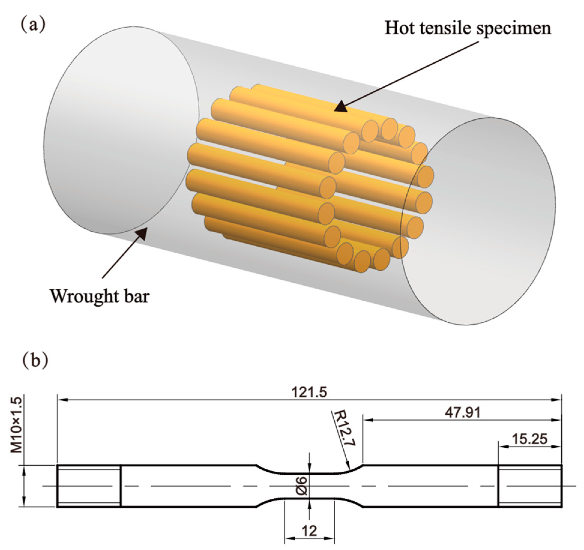
The material used in this study was commercially available 05Cr17Ni4Cu4Nb stainless steel, with its chemical composition provided in Table 1. The as-received material was tempered wrought bar. High-temperature tensile specimens were prepared from wrought bar using wire cutting and machining, with the sampling location shown in Figure 2a. A uniform sampling method along the circumferential direction of wrought bar was adopted to minimize structural inconsistencies caused by variations in sampling locations. This approach ensured the structural uniformity of the test specimens, thereby enhancing the reliability and accuracy of the test results. Following the guidelines of the Gleeble thermal simulator (SMR 311), cylindrical tensile specimens with a reduced-section gauge diameter of 6 mm and a parallel length of 12 mm were fabricated, as illustrated in Figure 2b. Uniaxial tensile tests were conducted using the Gleeble 3500 thermal simulator (Poestenkill, NY, USA). The Gleeble testing system utilizes direct resistance heating and employs thermocouples to monitor temperature changes in real time, enabling the formation of a uniform heating zone up to 25 mm long at the center of the specimen. The specimen is secured to the fixture using a threaded connection and is designed with a necked cross-section, as shown in Figure 2b, to ensure that plastic deformation is uniformly distributed across the 10 mm gauge length of the specimen. Before testing, the specimens were heated to deformation temperatures of 950 °C, 1050 °C, and 1150 °C at a controlled heating rate of 10 °C/s and held for 5 min to eliminate temperature gradients. Tensile tests were then performed at strain rates of 0.1, 1, and 10 s−1. After tensile fracture, the specimens were water-cooled to preserve the high-temperature deformation microstructure as effectively as possible. During the tensile process, the Gleeble 3500 thermal simulator recorded the load and displacement data through its integrated force-position sensors, with a sampling frequency of 1000 Hz. The load resolution is ±10 N, and the displacement resolution is ±0.01 mm. The stress–strain curve of the material was subsequently calculated using the following formula:
ε = ln l l 0 = ln l 0 + Δ l l 0
σ = F A = F l A 0 l 0 = F ( l 0 + Δ l ) A 0 l 0 = F A 0 1 + Δ l l 0
To further evaluate the effects of deformation process parameters on high-temperature tensile deformation and fracture behavior, the fracture characteristics and microstructures were analyzed using SEM (TESCAN, Brno, Czech Republic) and optical microscopy (EVIDENT, Guangzhou, China). Fractured specimens were sectioned along their central axis and etched at room temperature for 2 min using a solution of HCl (5 mL), ethanol (100 mL), and picric acid (2 g).
The initial microstructure of the material prior to the isothermal tensile tests is shown in Figure 3. In the metallographic field of view and under scanning electron signals, δ-ferrite and the matrix exhibit distinct differences in contrast and surface roughness, enabling clear differentiation between δ-ferrite and the matrix. A substantial amount of δ-ferrite was observed in a banded distribution along the axial direction of the 05Cr17Ni4Cu4Nb stainless steel bar. Measurements indicated that the diameter of the δ-ferrite ranged from 3 to 18 µm. This distribution is expected to significantly impact the material’s mechanical properties and crack propagation behavior during hot deformation.

3. Result and Discussion

3.1. Mechanical Response

Figure 4 illustrates the flow stress–strain curves of 05Cr17Ni4Cu4Nb stainless steel under various deformation conditions. At the initial stage of deformation, the material undergoes a significant dislocation proliferation due to the dominant mechanism of work hardening, leading to a sharp increase in stress over a small strain range. As deformation progresses, the dynamic softening effect becomes more pronounced, reducing the dislocation density through mechanisms such as dynamic recovery or dynamic recrystallization. This results in a gradual deceleration in the rate of stress increase. Once the material reaches its peak stress, the dynamic softening effects combined with the microvoid deterioration mechanism surpass the work hardening effect, causing the deformation resistance to decline [30].
Research [31] indicates that in metallic materials with low stacking fault energy, such as copper, brass, and stainless steel, the dominant softening mechanism during deformation is discontinuous dynamic recrystallization. During thermal deformation, dislocations tend to accumulate and proliferate extensively at original austenite grain boundaries or at the triple junctions of grain boundaries. When the dislocation density exceeds the critical threshold for dynamic recrystallization, recrystallized grains nucleate via grain boundary bowing and grow through grain boundary migration. As tensile deformation continues, plastic deformation becomes localized at the center of the specimen, leading to necking. Under the combined effects of the recrystallization softening mechanism and the microvoid deterioration mechanism, the specimen’s effective load-bearing area progressively decreases. Consequently, the material stress declines rapidly, ultimately resulting in specimen fracture.
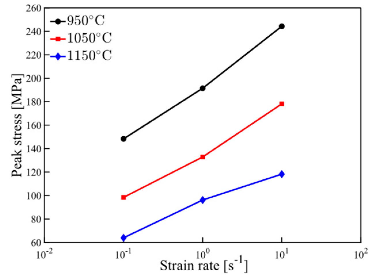
Figure 5 presents the extracted peak stresses of 05Cr17Ni4Cu4Nb stainless steel under various deformation conditions. The results reveal that the peak stress increases with rising strain rate and decreasing deformation temperature. At lower deformation temperatures, the rate of grain boundary migration within the alloy slows down, suppressing the softening effects associated with DRX and DRV mechanisms. Conversely, an increase in strain rate enhances the material’s work hardening effect and accelerates dislocation proliferation, resulting in a corresponding rise in peak stress.
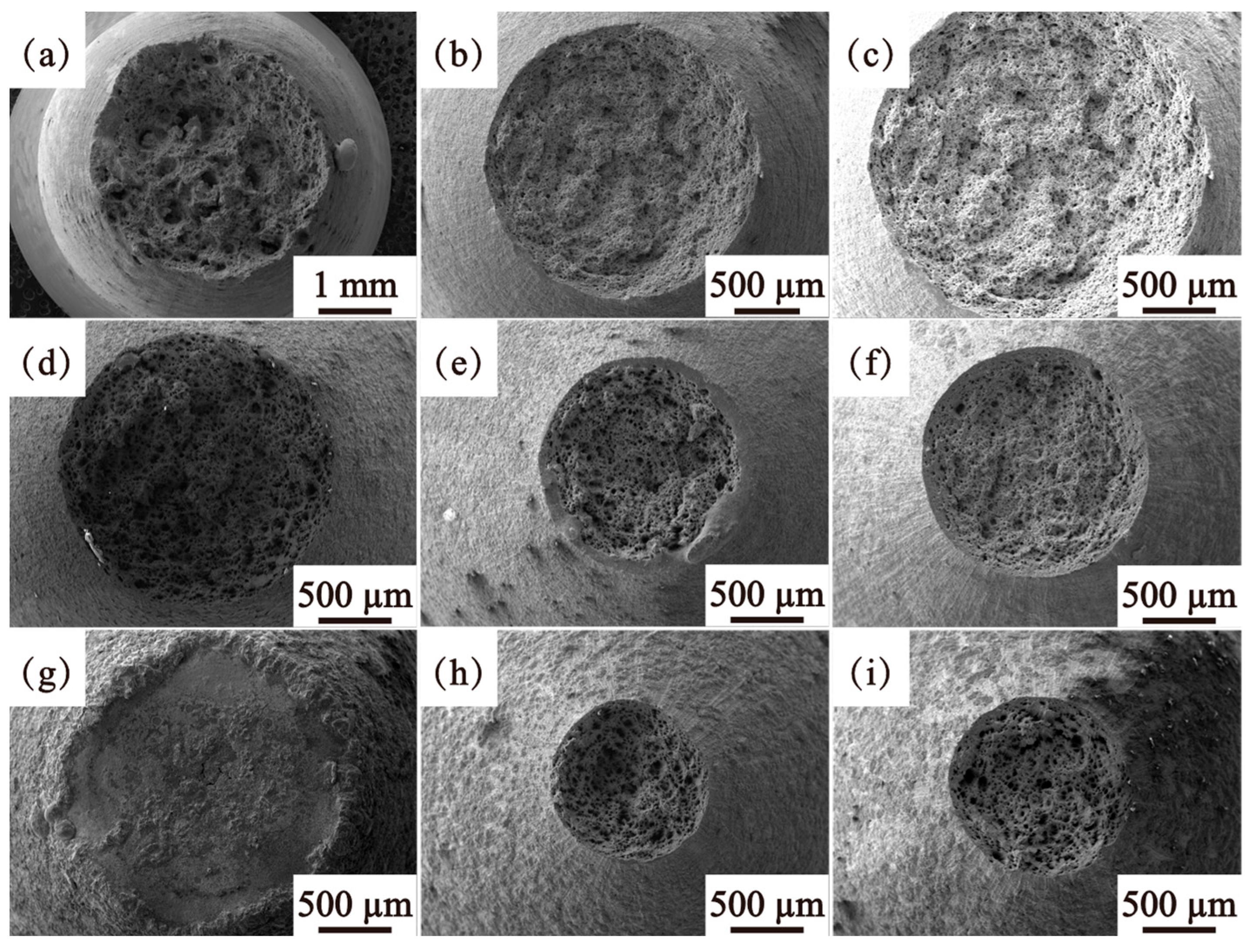
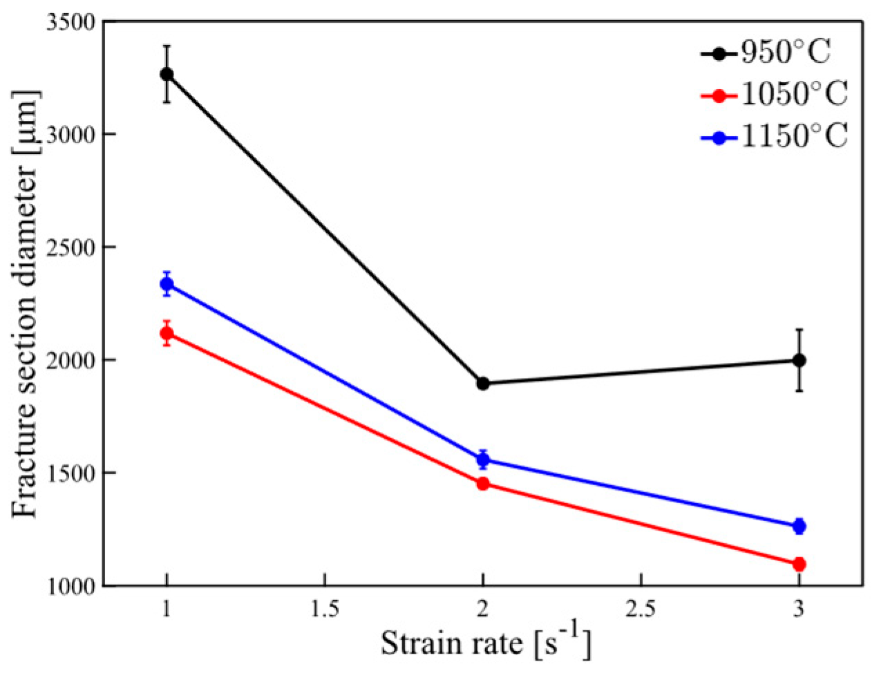
Figure 6 presents the macroscopic fracture morphology of 05Cr17Ni4Cu4Nb stainless steel under various deformation conditions. The fracture cross-sectional diameter of the specimens under the same test conditions was measured five times, and the mean value and error were calculated and presented in Figure 7. Measurements indicate that the fracture cross-sectional diameters vary depending on the deformation conditions, demonstrating that the degree of necking in the specimens is strongly influenced by the deformation environment.
It is observed that, except at a strain rate of 0.1 s−1, the degree of necking in the specimens increases with rising deformation temperature. Higher temperatures enhance atomic diffusion, which promotes the DRX behavior of 05Cr17Ni4Cu4Nb stainless steel. As noted in the reference [32], DRX effectively suppresses the nucleation and propagation of microvoids by eliminating dislocations and alleviating stress concentration. Consequently, elevated deformation temperatures allow 05Cr17Ni4Cu4Nb stainless steel to sustain greater plastic deformation.
Under the deformation temperature of 1150 °C and a strain rate of 0.1 s−1, as shown in Figure 6e, evidence of melting is observed on the material’s fracture surface, and the degree of necking in the specimen decreases. This phenomenon can be attributed to the limitations of the Gleeble testing system. During the necking deformation process, the system’s current does not adjust to account for the reduction in the specimen’s cross-sectional area. Consequently, the temperature of the specimen increases, resulting in premature fracture and rapid melting of the fracture surface.
It is also observed that as the strain rate increases, the degree of necking initially increases and then decreases. Notably, during the plastic deformation process, materials generally exhibit better ductility at lower strain rates. This is because, at reduced strain rates, atoms have ample time to accommodate deformation via diffusion, dislocation motion becomes more effective, and DRX/DRV are more likely to occur. However, the local stress softening behavior induced by the DRX/DRV causes plastic deformation to concentrate primarily at the δ-ferrite/matrix interface, facilitating the rapid propagation of microcracks along this interface.

3.2. Damage Model

In this study, the Cockroft & Latham (C&L) criterion is employed as the damage criterion to establish a damage model for 05Cr17Ni4Cu4Nb stainless steel. The mathematical expression for the C&L criterion is provided in Equation (3).
D = 0 ε f < σ 1 > d ε
The maximum principal stress criterion is extensively utilized for predicting material damage behavior during plastic deformation, and its effectiveness has been validated across a wide range of materials and complex stress state conditions [33,34,35,36]. This criterion was proposed based on room-temperature deformation conditions. At room temperature, the damage threshold of materials is generally a constant. However, some studies have reported that the damage threshold of materials during high-temperature deformation is strongly influenced by temperature and strain rate [17,37].
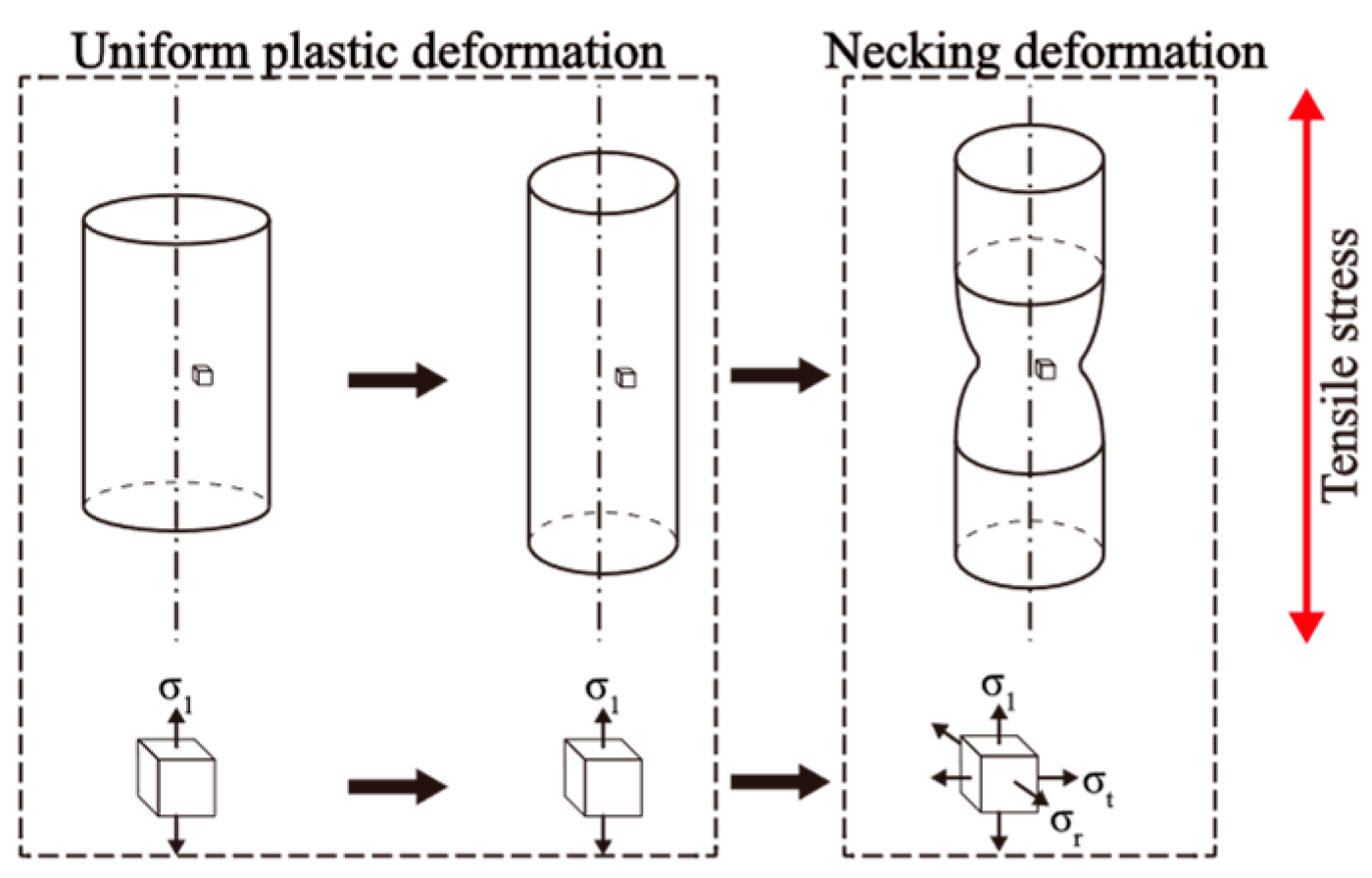
Figure 8 illustrates the stress state of the specimen during high-temperature tensile deformation. As deformation progresses, the specimen transitions from uniform plastic deformation to the necking stage. At this stage, the stress state at the center of the fracture cross-section shifts from uniaxial stress to triaxial stress. The triaxial stress state promotes the growth and coalescence of microvoids, facilitating the nucleation and rapid propagation of microcracks, which ultimately leads to specimen fracture.
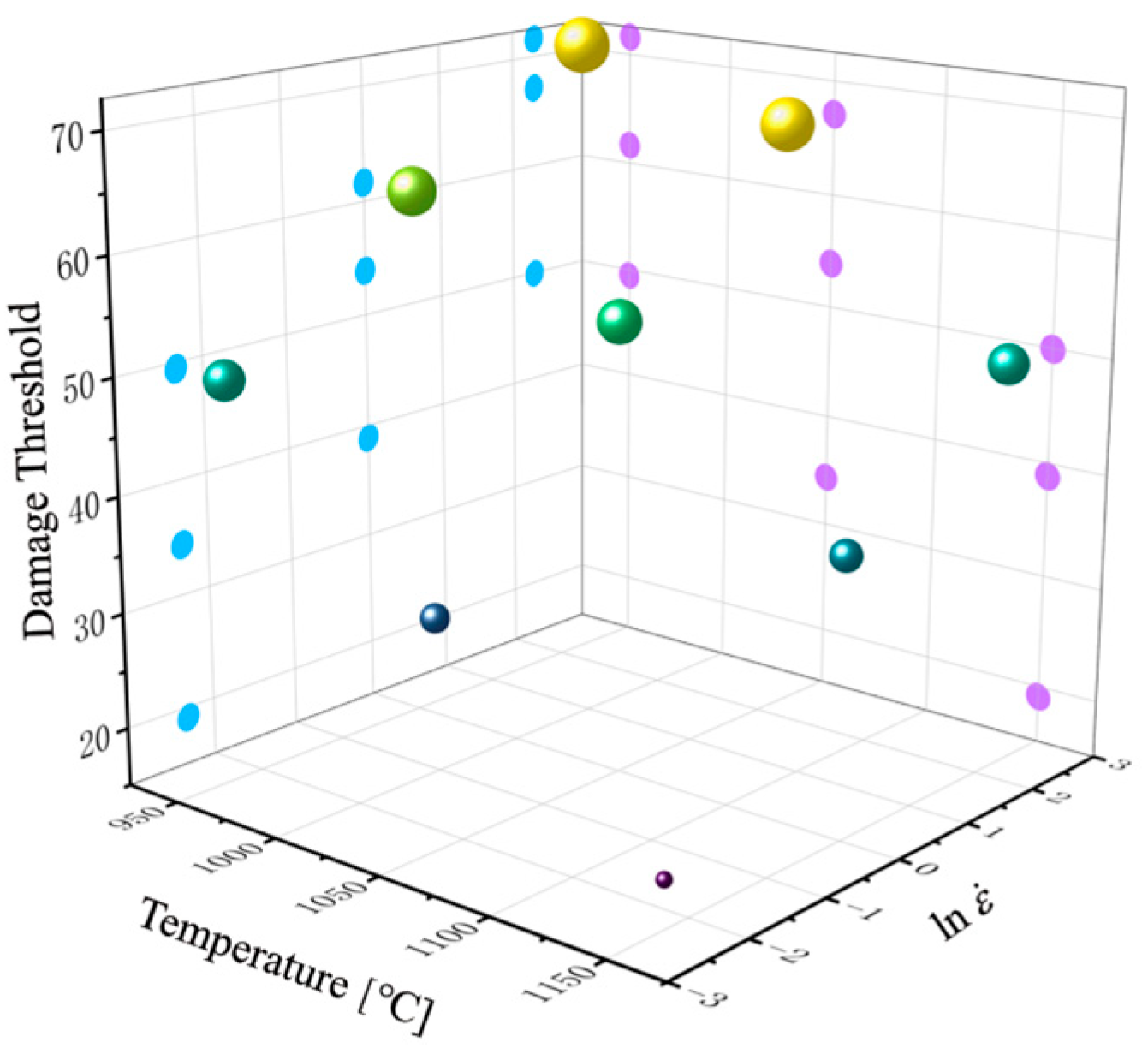
Due to the relatively straightforward nature of uniaxial tensile deformation, the tensile stress at the center of the fracture cross-section consistently corresponds to the maximum principal stress. Based on the stress–strain curves shown in Figure 4, the damage threshold of 05Cr17Ni4Cu4Nb stainless steel under various deformation conditions was calculated using the C&L criterion, with the results presented in Figure 9. The damage threshold of 05Cr17Ni4Cu4Nb stainless steel shows increasing flow stress with increasing strain rate and decreasing flow stress with rising temperature, following a trend consistent with that of the peak stress. This phenomenon can be attributed to the C&L criterion, which represents damage as a direct integration of stress and strain. Physically, this corresponds to plastic work, where stress has a more pronounced influence on damage.
The influence of temperature and strain rate on the high-temperature deformation behavior of materials can be characterized using the Z parameter [38]. Physically, the Z parameter represents the strain rate factor compensated by temperature. The mathematical expression of the Z parameter is shown in Equation (4). By incorporating the Z parameter to describe the combined effects of temperature and strain rate, the fitting formula for the damage threshold is simplified, offering a clearer understanding of damage evolution under these conditions.
Z = ε ˙ exp Q R T
In the equation, R represents the gas constant, and Q is the activation energy associated with the alloy’s deformation process, which is determined through Arrhenius equation fitting. The hyperbolic sine form of the Arrhenius equation is expressed as follows:
ε ˙ = A 1 [ sinh ( α σ ) ] n   e Q R T
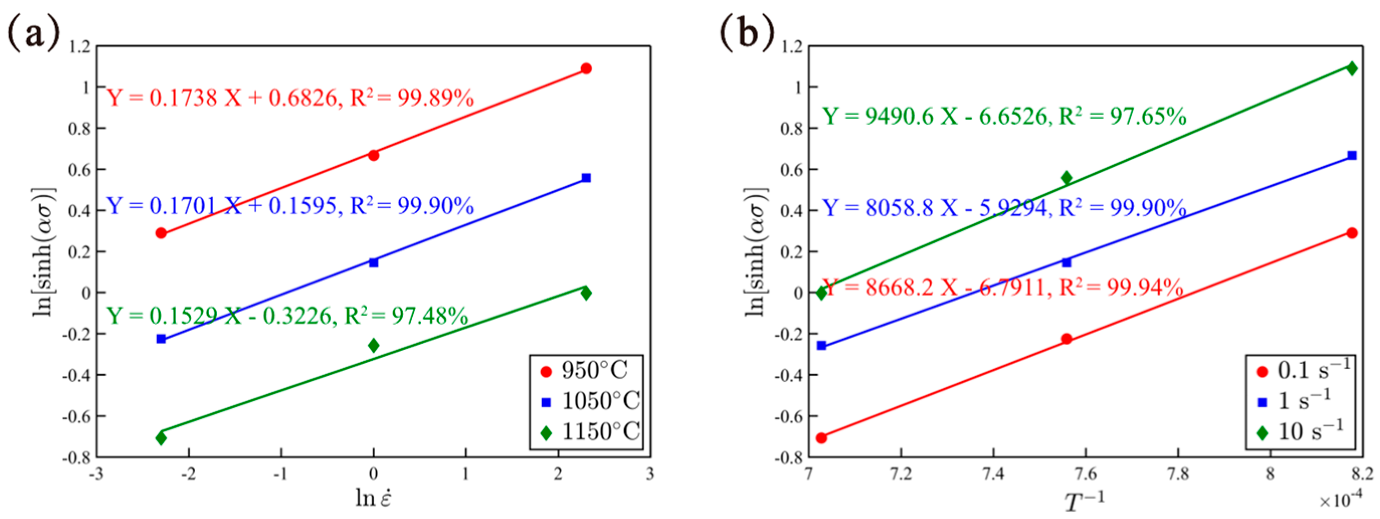
α and A1 are constants independent of temperature, and the reference [26] provides specific formulas for calculating α and A1. As shown in Figure 10, the value of constant n was determined to be 6.0309 by performing linear regression between l n sinh α σ p and l n ε ˙   under different deformation temperatures and calculating the average of their slopes. Similarly, the activation energy Q is determined as 438,943.34 J/mol via linear regression between l n sinh α σ p and T−1 under different deformation temperatures and using the calculation of the average of their slopes.
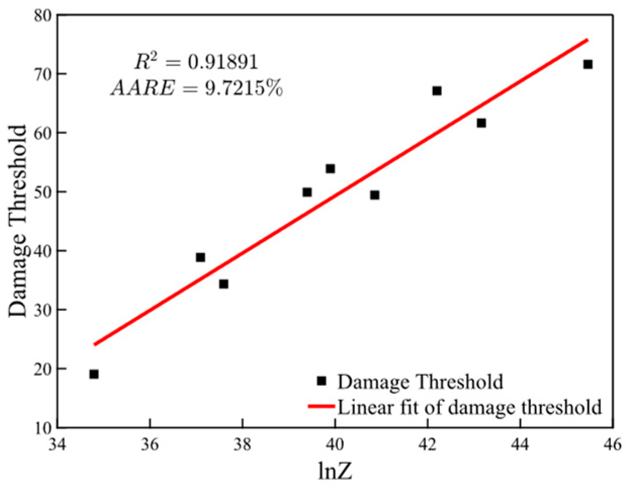
Figure 11 depicts the damage threshold and the corresponding linear fitting results of lnZ under different deformation conditions for 05Cr17Ni4Cu4Nb stainless steel. We introduced the linear correlation coefficient (R2) and the average absolute relative error (AARE) to evaluate the reliability of the model. The results show that R2 between the damage threshold and the lnZ parameter reaches 91.89%, demonstrating that Equation (6) effectively incorporates the effects of strain rate and temperature on the damage value. Furthermore, AARE between the damage threshold and the lnZ parameter is less than 10%, providing additional confirmation of the model’s reliability.
In summary, the improved C&L damage model, which effectively characterizes damage behavior under varying deformation conditions, is presented as Equation (6).
D c ( T , ε ˙ ) = 4.855 × ln Z 144.9 Z = ε ˙ exp 438943.34 R T

3.3. Fracture Characteristics

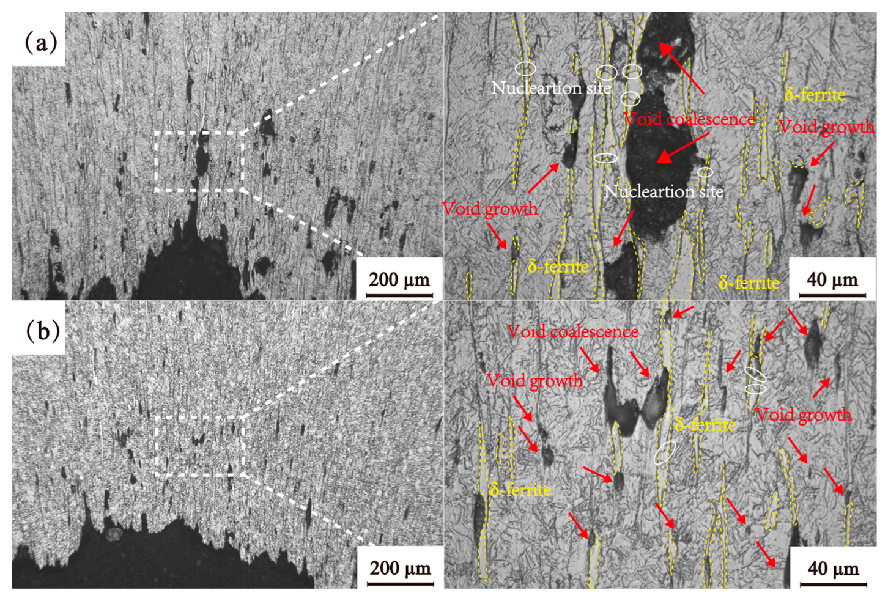
To further clarify the fracture mechanism of 05Cr17Ni4Cu4Nb stainless steel, this study investigates its microcrack propagation behavior under different strain rates, as illustrated in Figure 12. From Figure 12a, it is evident that at low strain rates, the number of microvoids is relatively small. Microvoid growth and coalescence are observed only around δ-ferrite. This observation indicates that, at low strain rates, the dominant fracture mechanism of 05Cr17Ni4Cu4Nb stainless steel is the rapid growth of microvoids along the δ-ferrite interface after their formation. It is also observed that δ-ferrite itself begins to fracture. The reference [39] has reported that the fracture of relatively soft second-phase particles can also lead to the nucleation of microvoids within the material.
DRX requires a certain “incubation period” [40,41]. As the strain rate gradually increases, the DRX behavior of 05Cr17Ni4Cu4Nb stainless steel at δ-ferrite interfaces and grain boundaries becomes insufficient. Dislocation pile-up and pinning at the δ-ferrite interface induce work hardening, which extends plastic deformation into the matrix. At this stage, the degree of necking of 05Cr17Ni4Cu4Nb stainless steel increases. As the strain rate continues to rise to 10 s−1, significant dislocation multiplication occurs at the δ-ferrite/matrix interface and grain boundaries. These dislocations cannot be sufficiently eliminated through DRX and DRV. Consequently, the pinning and pile-up of dislocations lead to extensive microvoid nucleation [42,43], which reduces the degree of necking. Figure 12b illustrates the microvoid evolution behavior of 05Cr17Ni4Cu4Nb stainless steel under high strain rates. It is evident that the nucleation sites of microvoids are more uniformly distributed, and the number of microvoids increases significantly. This observation provides evidence for the evolution of microvoids in 05Cr17Ni4Cu4Nb stainless steel.
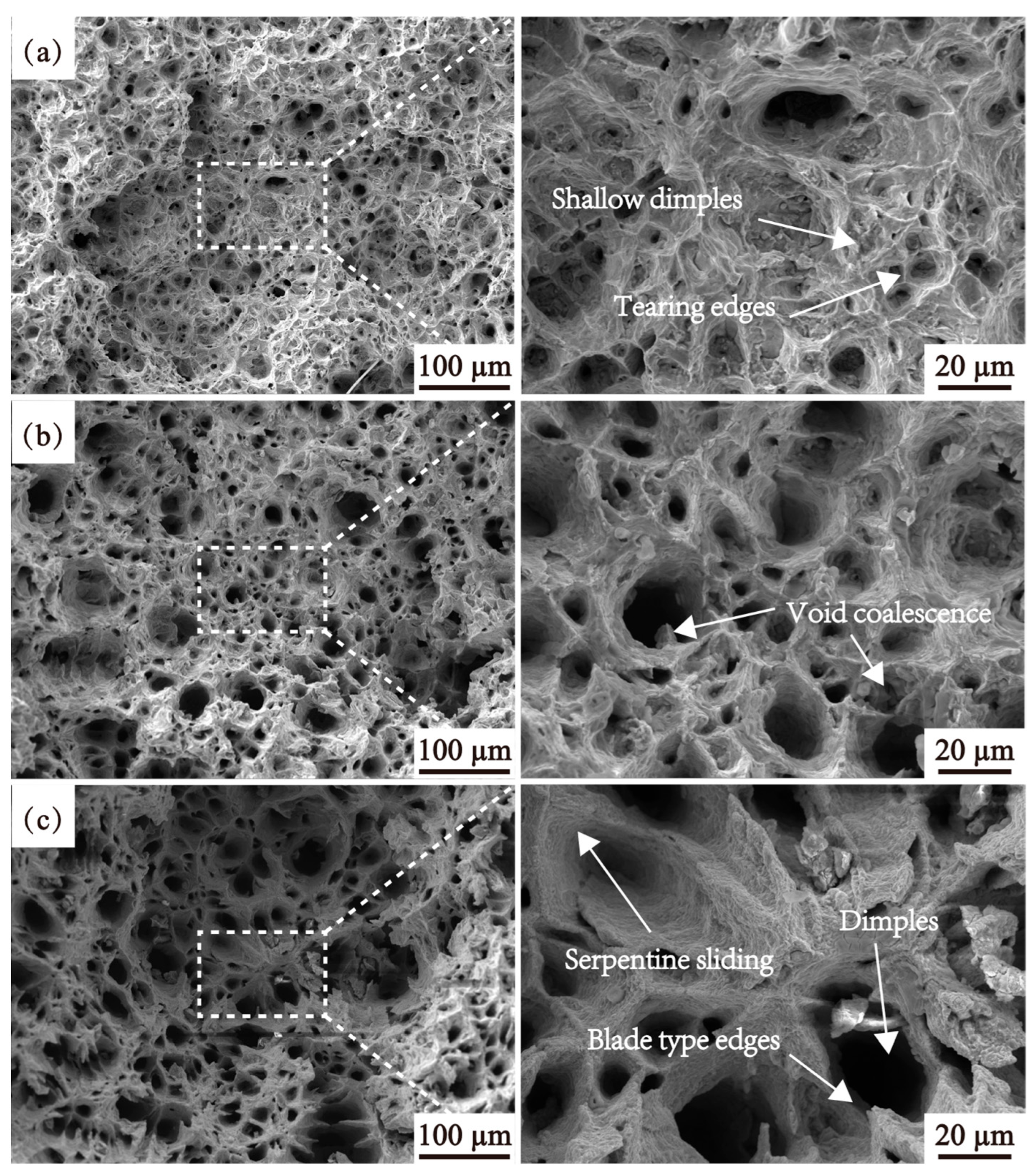
Figure 13 presents the microscopic fracture morphology of 05Cr17Ni4Cu4Nb stainless steel at a strain rate of 1 s−1 under different deformation temperatures. As the deformation temperature increases, the tearing ridge features become more pronounced, and the surface roughness of the tearing ridges decreases further. Figure 13c highlights a blade-like edge characteristic of the fracture, indicating that elevated temperatures enhance plastic deformation in the necking regions during void coalescence. High-resolution images in Figure 13 reveal distinct serpentine slip patterns on the sidewalls of larger dimples. These patterns form because, in polycrystalline materials, grains with different orientations constrain and interact with one another, generating cross-slip within the material. This interaction causes the separation of slip planes, resulting in wavy, striped structures with undulating features.
As the deformation temperature continues to rise, the size and depth of the dimples increase, while their number decreases. This behavior can be attributed to the enhanced strain coordination capability of the material at high temperatures. Once microvoids initially form and grow to a certain size, they undergo repeated coalescence. The void coalescence observed in Figure 13b and the large dimples in Figure 13c indicate that, at higher deformation temperatures, the necking regions favor the continued growth and coalescence of pre-existing voids rather than the formation of new microvoids.
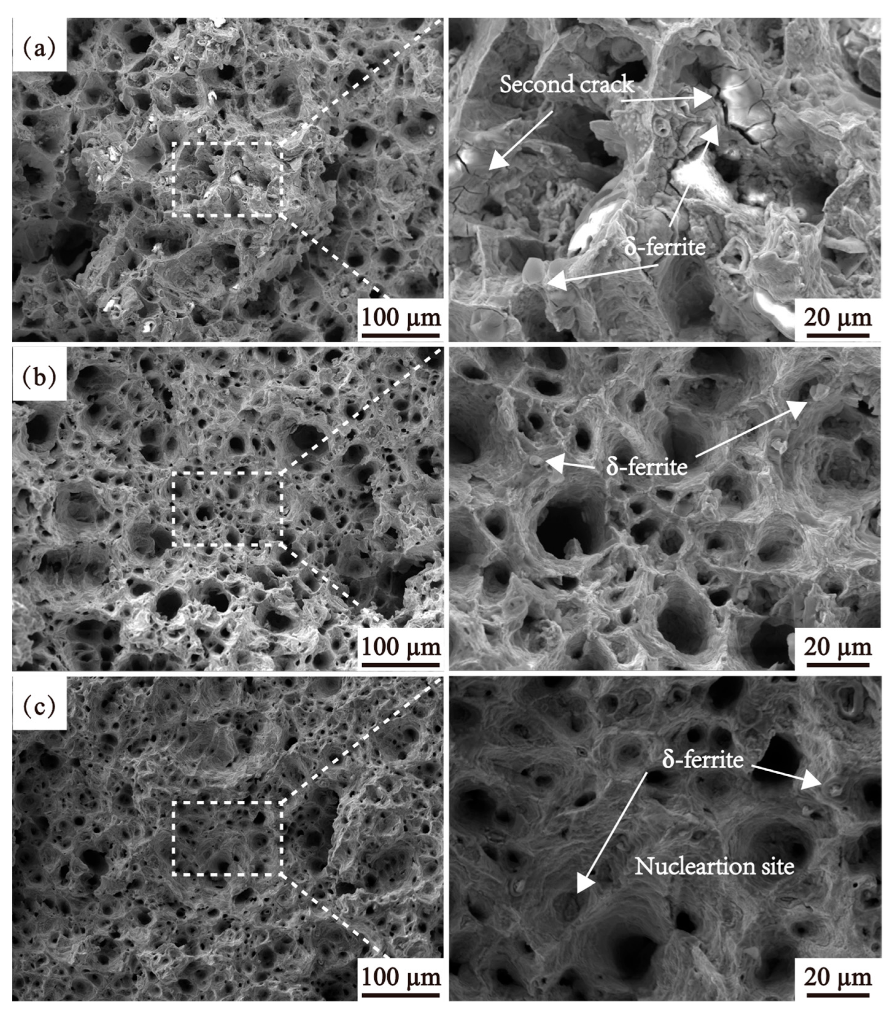
Figure 14 presents the microscopic fracture morphology of 05Cr17Ni4Cu4Nb stainless steel at 1050 °C under different strain rates. High-resolution images reveal the presence of δ-ferrite at the bottom of the dimples, suggesting that δ-ferrite serves as a nucleation site for microvoids during the tensile deformation process. The nucleation behavior of microvoids is relatively complex. It typically occurs when second-phase particles in ductile metals separate from the matrix due to strain incompatibility during plastic deformation. Additionally, the fracture of relatively softer second-phase particles can also contribute to the nucleation of microvoids within the material. As a soft phase, δ-ferrite is particularly susceptible to fracture during plastic deformation due to its deformation incompatibility with the surrounding matrix. The fractured δ-ferrite further promotes the nucleation of microvoids.
Figure 14a shows secondary cracks at the interface between δ-ferrite and the matrix, as well as on the surface of δ-ferrite. This observation suggests that during plastic deformation, δ-ferrite fractures and separates from the matrix due to deformation incompatibility with the surrounding matrix. Notably, as the strain rate increases, the size of δ-ferrite observed on the fracture surface decreases significantly. This variation is likely attributed to differences in the fracture behavior of δ-ferrite under varying strain rates. The reference [44] also reports that δ-ferrite exhibits distinct morphological differences at different strain rates. At low strain rates, δ-ferrite splits gradually, resulting in larger δ-ferrite fragments detectable in the microstructure. In contrast, at high strain rates, δ-ferrite fractures rapidly, leaving only smaller δ-ferrite fragments within the microstructure.
In summary, at high deformation temperatures, DRX occurs more readily, suppressing the nucleation of microvoids. This observation aligns with the findings reported in [39,41]. A comprehensive analysis of the microvoid evolution behavior and fracture surface morphology of 05Cr17Ni4Cu4Nb stainless steel under different strain rates provides a systematic insight into the ductility fracture mechanism. This understanding is depicted in the schematic diagram shown in Figure 15. The rapid fracture of 05Cr17Ni4Cu4Nb stainless steel at low strain rates is attributed to strain localization at the δ-ferrite/matrix interface. At low strain rates, the δ-ferrite and matrix exhibit lower cooperative deformation capacity relative to adjacent grains. Consequently, dislocations preferentially accumulate at the δ-ferrite interface, leading to the nucleation, growth, and coalescence of microvoids in this region. In contrast, at high strain rates, dislocations multiply extensively at the δ-ferrite/matrix interface and grain boundaries, and all of them cannot be sufficiently eliminated through DRX or DRV. As a result, the nucleation sites of microvoids become more dispersed.

4. Conclusions

The thermal tensile behaviors of 05Cr17Ni4Cu4Nb stainless steel are investigated by conducting hot tensile experiments under wide tensile processing parameters. Some important conclusions are summarized as the following:
(1) A damage model for 05Cr17Ni4Cu4Nb stainless steel, which accounts for temperature and strain rate, was developed based on the maximum principal stress damage criterion. The model demonstrates a 91.89% linear correlation with the Zener–Holloman parameter, which provides a reliable tool for predicting damage evolution during high-temperature deformation.
(2) As the deformation temperature increases, 05Cr17Ni4Cu4Nb stainless steel tends to support the continued growth and coalescence of pre-existing voids rather than the formation of new voids. This results in larger and deeper dimples with reduced numbers, contributing to a better understanding of ductile fracture mechanisms in stainless steels.
(3) At low strain rates, the primary fracture mechanism is the rapid growth of voids along the δ-ferrite/matrix interface after their nucleation. At high strain rates, deformation is dominated by widespread dislocation activity and microvoid formation, providing insight into strain rate effects on fracture behavior.
(4) Establishing damage models through multiple replicate experiments or developing crystal plasticity finite element models based on δ-ferrite morphology and distribution will significantly further enhance the predictive capability and statistical reliability for industrial applications of 05Cr17Ni4Cu4Nb stainless steel hot forming processes.

Author Contributions

Software, H.J.; Validation, L.Z.; Formal analysis, K.Z.; Writing—original draft, J.Y.; Writing—review & editing, J.Y. All authors have read and agreed to the published version of the manuscript.

Funding

This research was funded by the following grants: Shaanxi Railway Institute 2025 Scientific Research Fund Project Plan (No. 2025KYYB-11), Research Project on Vocational Education Teaching Reform of the Shaanxi Vocational and Technical Education Society in 2024 (No. 2024SZX337), Scientific Research Program of the Education Department of the Shaanxi Provincial Government (No. 24JK0387).

Data Availability Statement

The original contributions presented in this study are included in the article. Further inquiries can be directed to the corresponding author.

Conflicts of Interest

The authors declare no conflict of interest.

Nomenclature

ε Strain
ε ˙ Strain rate
εfFracture strain
ε p Peak strain
σ Stress
σ1Maximum principal stress
σ p Peak stress
TTemperature
l Actual length of the gauge section
l Elongation of the gauge section
AActual cross-sectional area of the parallel section
AoOriginal cross-sectional area of the parallel section
FTensile load
D Damage value
D c Damage threshold
α Constant determined through Arrhenius equation fitting
A1Constant determined through Arrhenius equation fitting
nConstant determined through Arrhenius equation fitting
RGas constant, 8.314 J/(mol · K)
QActivation energy
ZStrain rate factor compensated by temperature
R2Linear correlation coefficient
AAREAverage absolute relative error
XIndependent variable
YDependent variable

References

  1. Wang, L.; Hu, H.; Wang, W.; He, P.; Li, Z.; Xu, G. Analysis on the Key Parameters to Predict Flow Stress during Ausforming in a High-Carbon Bainitic Steel. Metals 2023, 13, 1526. [Google Scholar] [CrossRef]
  2. Wu, S.; Qu, R.; Zhu, Z.; Zhang, H.; Zhang, Z. Deformation Map of Metallic Glass: Normal Stress Effect. Sci. China Mater. 2020, 63, 2620–2626. [Google Scholar] [CrossRef]
  3. Mahnken, R.; Stein, E. Parameter Identification for Finite Deformation Elasto-Plasticity in Principal Directions. Comput. Methods Appl. Mech. Eng. 1997, 147, 17–39. [Google Scholar] [CrossRef]
  4. Melzer, D.; Smirnov, I.; Lukáš, O.; Dlouhý, J.; Evstifeev, A.; Džugan, J.; Valiev, R. Fracture Locus Characteristics of Al Alloy 5083 Processed by Equal Channel Angular Pressing Using Miniaturized Specimens. J. Alloys Compd. 2021, 889, 161675. [Google Scholar] [CrossRef]
  5. Brünig, M.; Albrecht, D.; Gerke, S. Numerical Analyses of Stress-Triaxiality-Dependent Inelastic Deformation Behavior of Aluminum Alloys. Int. J. Damage Mech. 2011, 20, 299–317. [Google Scholar] [CrossRef]
  6. Wei, X.; Zhang, X.; Cai, M.; Peng, Z.; Liu, Y.; Lian, C.; Peng, H.; Hodgson, P. Stress-State-Dependent Deformation and Fracture Behaviors in a Cold-Rolled 7Mn Steel. Mater. Sci. Eng. A 2022, 831, 142102. [Google Scholar] [CrossRef]
  7. McQueen, H.J.; Imbert, C.A.C. Dynamic Recrystallization: Plasticity Enhancing Structural Development. J. Alloys Compd. 2004, 378, 35–43. [Google Scholar] [CrossRef]
  8. Abedi, H.R.; Zarei Hanzaki, A.; Liu, Z.; Xin, R.; Haghdadi, N.; Hodgson, P.D. Continuous Dynamic Recrystallization in Low Density Steel. Mater. Des. 2017, 114, 55–64. [Google Scholar] [CrossRef]
  9. Huang, S.H.; Chen, T.; Chen, Q.; Zhao, Z.D.; Xia, X.S.; Wu, Y. Verification of Dislocation Density and Dynamic Recrystallization in Deformed Pure Copper. Strength Mater 2020, 52, 16–23. [Google Scholar] [CrossRef]
  10. Peng, Y.; Liang, S.; Liu, C.; Barella, S.; Guo, S.; Gruttadauria, A.; Belfi, M.; Liu, Y.; Qu, X.; Mapelli, C. Dynamic Recrystallization Behavior Under Inhomogeneous Thermomechanical Deformation State. Steel Res. Int. 2023, 94, 2200574. [Google Scholar] [CrossRef]
  11. Mi, G.; Zhang, J.; Xu, B.; Sun, M. Surface Stress Evolution and Cracks Prevention of Ingots during the Upsetting Process. Eng. Rev. 2019, 39, 292–301. [Google Scholar] [CrossRef]
  12. Lezhnev, S.; Naizabekov, A.; Panin, E.; Tolkushkin, A.; Kuis, D.; Kasperovich, A.; Yordanova, R. Development and Computer Simulation of the New Combined Process for Producing a Rebar Profile. Model. Simul. Eng. 2023, 2023, 7348592. [Google Scholar] [CrossRef]
  13. Krishna, R.H.; Jena, D.P. Analytical and Numerical Modelling of Open-Die Forging Process for Elliptical Cross-Section of Billet. Measurement 2019, 134, 855–865. [Google Scholar] [CrossRef]
  14. Fanini, S.; Ghiotti, A.; Bruschi, S. Prediction Of The Fracture Due To Mannesmann Effect In Tube Piercing. AIP Conf. Proc. 2007, 908, 1407–1412. [Google Scholar] [CrossRef]
  15. Ghiotti, A.; Fanini, S.; Bruschi, S.; Bariani, P.F. Modelling of the Mannesmann Effect. CIRP Ann. 2009, 58, 255–258. [Google Scholar] [CrossRef]
  16. Fernandes, M.; Marouf, N.; Montmitonnet, P.; Mocellin, K. Impact of the Different Friction Coefficients on the Tools on the Mechanics of the Mannesmann 2-Roll Tube Piercing. ISIJ Int. 2020, 60, 2917–2926. [Google Scholar] [CrossRef]
  17. Zhang, Z.; Liu, D.; Man, T.; Li, N.; Yang, Y.; Pang, Y.; Wang, J. Numerical and Experimental Investigations on Mannesmann Effect of Nickel-Based Superalloy. Arch. Civ. Mech. Eng. 2022, 22, 133. [Google Scholar] [CrossRef]
  18. Mackenzie, A.C.; Hancock, J.W.; Brown, D.K. On the Influence of State of Stress on Ductile Failure Initiation in High Strength Steels. Eng. Fract. Mech. 1977, 9, 167–188. [Google Scholar] [CrossRef]
  19. Meade, E.D.; Sun, F.; Tiernan, P.; O’Dowd, N.P. A Multiscale Experimentally-Based Finite Element Model to Predict Microstructure and Damage Evolution in Martensitic Steels. Int. J. Plast. 2021, 139, 102966. [Google Scholar] [CrossRef]
  20. Hu, P.; Liu, Y.; Zhu, Y.; Ying, L. Crystal Plasticity Extended Models Based on Thermal Mechanism and Damage Functions: Application to Multiscale Modeling of Aluminum Alloy Tensile Behavior. Int. J. Plast. 2016, 86, 1–25. [Google Scholar] [CrossRef]
  21. Wang, C.; Liu, X.; Gui, J.; Du, Z.; Xu, Z.; Guo, B. Effect of MnS Inclusions on Plastic Deformation and Fracture Behavior of the Steel Matrix at High Temperature. Vacuum 2020, 174, 109209. [Google Scholar] [CrossRef]
  22. Liu, Y.; Liu, J.; He, Y. Formation Mechanism and Evolution of Plastic Damage in Billet during Reduction Pretreatment. Metals 2023, 13, 747. [Google Scholar] [CrossRef]
  23. Chen, X.; Lu, Y.; Ning, M.; Zhou, X.; Chen, J. Tailoring Microstructural Evolution and Fracture Damage Behavior of a Mg–Y–Zn Alloy during Hot Tensile Deformation. Mater. Sci. Eng. A 2023, 871, 144857. [Google Scholar] [CrossRef]
  24. Wu, H.; Qian, Q.; Xu, W.; Liu, C.; Xu, J.; Shan, D.; Guo, B. A Thermal Damage-Coupled Constitutive Model for Predicting Fracture and Microstructure Evolution and Its Application in the Hot Spinnability Process. J. Mater. Res. Technol. 2024, 30, 1594–1610. [Google Scholar] [CrossRef]
  25. Xu, W.; Wu, H.; Ma, H.; Shan, D. Damage Evolution and Ductile Fracture Prediction during Tube Spinning of Titanium Alloy. Int. J. Mech. Sci. 2018, 135, 226–239. [Google Scholar] [CrossRef]
  26. Xiao, Y.; Cui, Z.; Yin, H.; Guo, C. High Temperature Deformation Behavior and Constitutive Modelling for 05Cr17Ni4Cu4Nb Stainless Steel. Procedia Eng. 2014, 81, 1277–1282. [Google Scholar] [CrossRef]
  27. Zhang, J.-L.; Jia, H.-S.; Yi, X.-B.; Xu, C.-W.; Luo, W.-C.; Tang, L.-H.; Shen, J.-C.; Li, X. Dynamic Mechanical Properties and Comparison of Two Constitutive Models for Martensitic Stainless Steel 0Cr17Ni4Cu4Nb. Mater. Res. Express 2021, 8, 106501. [Google Scholar] [CrossRef]
  28. Zhu, L.; Huang, X.; Liu, H. Study on Constitutive Model of 05Cr17Ni4Cu4Nb Stainless Steel Based on Quasi-Static Tensile Test. J. Mech. Sci. Technol. 2022, 36, 2871–2878. [Google Scholar] [CrossRef]
  29. Guo, J.; Wu, L.; Yang, X.; Zhong, S. Elastic-Plastic Endochronic Constitutive Model of 0Crl7Ni4Cu4Nb Stainless Steels. Math. Probl. Eng. 2016, 2016, 4396296. [Google Scholar] [CrossRef]
  30. Li, J.; Wang, B.; Huang, H.; Fang, S.; Chen, P.; Zhao, J.; Qin, Y. Behaviour and Constitutive Modelling of Ductile Damage of Ti-6Al-1.5Cr-2.5Mo-0.5Fe-0.3Si Alloy under Hot Tensile Deformation. J. Alloys Compd. 2019, 780, 284–292. [Google Scholar] [CrossRef]
  31. Sakai, T.; Belyakov, A.; Kaibyshev, R.; Miura, H.; Jonas, J.J. Dynamic and Post-Dynamic Recrystallization under Hot, Cold and Severe Plastic Deformation Conditions. Prog. Mater. Sci. 2014, 60, 130–207. [Google Scholar] [CrossRef]
  32. Noell, P.J.; Sills, R.B.; Boyce, B.L. Suppression of Void Nucleation in High-Purity Aluminum via Dynamic Recrystallization. Metall. Mater. Trans. A 2020, 51, 154–166. [Google Scholar] [CrossRef]
  33. Mirsayar, M.M. Maximum Principal Strain Criterion for Fracture in Orthotropic Composites under Combined Tensile/Shear Loading. Theor. Appl. Fract. Mech. 2022, 118, 103291. [Google Scholar] [CrossRef]
  34. Cao, T.; Gong, Y.; Zhao, L.; Wang, L.; Hu, N. Stress Based Fracture Criteria for Mixed-Mode I/II Delamination of Unidirectional Composite Laminates. Compos. Struct. 2024, 344, 118325. [Google Scholar] [CrossRef]
  35. Gerke, S.; Valencia, F.R.; Norz, R.; Volk, W.; Brünig, M. Damage and Fracture in Thin Metal Sheets: New Biaxial Experiments. Adv. Ind. Manuf. Eng. 2023, 7, 100129. [Google Scholar] [CrossRef]
  36. Abdolvand, H. Development of Microstructure-Sensitive Damage Models for Zirconium Polycrystals. Int. J. Plast. 2022, 149, 103156. [Google Scholar] [CrossRef]
  37. Zhu, Y.; Zeng, W.; Zhang, F.; Zhao, Y.; Zhang, X.; Wang, K. A New Methodology for Prediction of Fracture Initiation in Hot Compression of Ti40 Titanium Alloy. Mater. Sci. Eng. A 2012, 553, 112–118. [Google Scholar] [CrossRef]
  38. Sellars, C.M.; Whiteman, J.A. Recrystallization and Grain Growth in Hot Rolling. Met. Sci. 1979, 13, 187–194. [Google Scholar] [CrossRef]
  39. Maire, E.; Bouaziz, O.; Di Michiel, M.; Verdu, C. Initiation and Growth of Damage in a Dual-Phase Steel Observed by X-Ray Microtomography. Acta Mater. 2008, 56, 4954–4964. [Google Scholar] [CrossRef]
  40. Huang, K.; Logé, R.E.; Marthinsen, K. On the Sluggish Recrystallization of a Cold-Rolled Al–Mn–Fe–Si Alloy. J. Mater. Sci. 2016, 51, 1632–1643. [Google Scholar] [CrossRef]
  41. Luton, M.J.; Sellars, C.M. Dynamic Recrystallization in Nickel and Nickel-Iron Alloys during High Temperature Deformation. Acta Metall. 1969, 17, 1033–1043. [Google Scholar] [CrossRef]
  42. Wilkerson, J.W.; Ramesh, K.T. A Dynamic Void Growth Model Governed by Dislocation Kinetics. J. Mech. Phys. Solids 2014, 70, 262–280. [Google Scholar] [CrossRef]
  43. Chen, W.; Zeng, X.; Chen, L.; Yang, X.; Wang, F. Competition between Plasticity- and Void-Based Dynamic Damage Behaviors of Single Crystal HCP-Zr by Considering the High Strain Rate and Temperature. Mech. Mater. 2020, 141, 103261. [Google Scholar] [CrossRef]
  44. Derazkola, H.A.; Gil, E.G.; Murillo-Marrodan, A. Analysis of Super Cr13 Stainless-Steel Internal Fracture Growth Effects during Skew Mill Piercing Process. Results Eng. 2024, 21, 101682. [Google Scholar] [CrossRef]
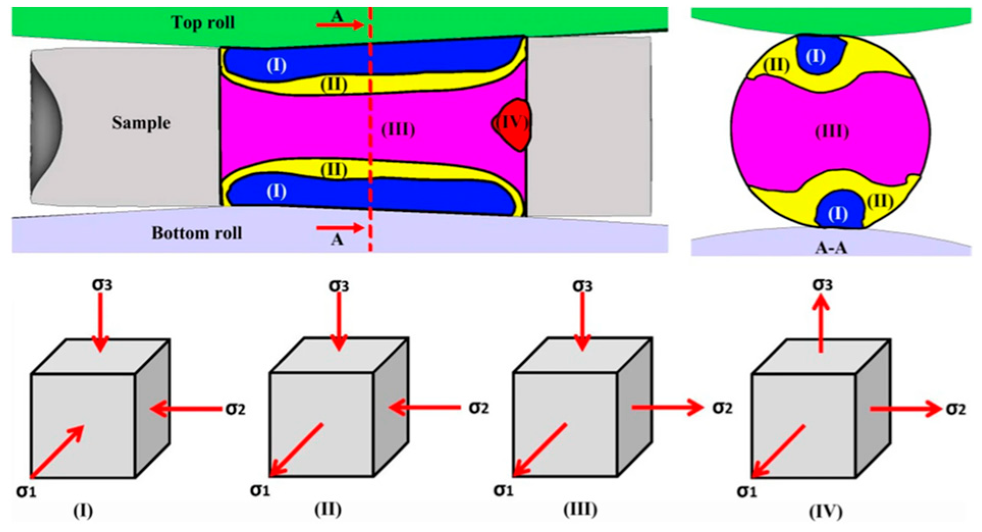
Figure 1. The schematic diagram of principal stress Reprinted with permission from ref. [17].
Metals 15 00776 g001
Figure 2. (a) A drawing of sampling positions. (b) Engineering drawing of round tensile bar specimen.
Metals 15 00776 g002
Figure 3. Microstructure of raw materials.
Metals 15 00776 g003
Figure 4. The stress–strain curves of the 05Cr17Ni4Cu4Nb stainless steel at (a) 1 s−1 and (b) 1050 °C.
Metals 15 00776 g004
Figure 5. Peak stress of the 05Cr17Ni4Cu4Nb stainless steel.
Metals 15 00776 g005
Figure 6. The macroscopic fracture morphology of the following: (a) 0.1 s−1, 950 °C; (b) 0.1 s−1, 950 °C; (c) 0.1 s−1, 950 °C; (d) 0.1 s−1, 1050 °C; (e) 1 s−1, 1050 °C; (f) 1 s−1, 1050 °C; (g) 10 s−1, 1150 °C; (h) 10 s−1, 1150 °C; (i) 10 s−1, 1150 °C.
Metals 15 00776 g006
Figure 7. Fracture cross-sectional diameter of the 05Cr17Ni4Cu4Nb stainless steel.
Metals 15 00776 g007
Figure 8. Stress state of specimen during unidirectional tension.
Metals 15 00776 g008
Figure 9. Damage threshold of 05Cr17Ni4Cu4Nb stainless steel under different deformation conditions.
Metals 15 00776 g009
Figure 10. Relationship between peak stress, strain rate, and temperature is as follows: (a) l n sinh α σ p l n ε ˙ ; (b) l n sinh α σ p − T−1.
Metals 15 00776 g010
Figure 11. Fitting of damage model.
Metals 15 00776 g011
Figure 12. OM images at the tensile temperature of 1050 °C and strain rate of (a) 0.1 s−1 and (b) 10 s−1.
Metals 15 00776 g012
Figure 13. Fracture morphology at the strain rate of 1 s−1 and tensile temperature of (a) 950 °C, (b) 1050 °C, and (c) 1150 °C.
Metals 15 00776 g013
Figure 14. Fracture morphology at the tensile temperature of 1050 °C and strain rate of (a) 0.1 s−1, (b) 1 s−1, and (c) 10 s−1.
Metals 15 00776 g014
Figure 15. Schematic view of the evolution behavior of the ductile fracture mechanism.
Metals 15 00776 g015
Table 1. Chemical composition of 05Cr17Ni4Cu4Nb stainless steel (mass fraction/%).
ElementCrNiCuNbCSiMnFe
Ingredient16.753.903.520.250.060.700.42Bal.
Disclaimer/Publisher’s Note: The statements, opinions and data contained in all publications are solely those of the individual author(s) and contributor(s) and not of MDPI and/or the editor(s). MDPI and/or the editor(s) disclaim responsibility for any injury to people or property resulting from any ideas, methods, instructions or products referred to in the content.