Abstract
Under the global initiative for automotive lightweighting to address climate challenges, this study investigates the microstructure evolution of steel–aluminum composites processed by hot equal-channel angular pressing (H-ECAP). Using 6061-T6 aluminum cores clad with 20 # low carbon steel tubes processed through 1–4 C-path passes (Φ = 120°, ψ = 30°), we demonstrate significant microstructural improvements. The steel component showed progressive grain refinement from 2.2 μm (1 pass) to 1.3 μm (4 pass), with substructures decreasing from 72.19% to 35.46%, HAGB increasing from 31.2% to 34.6%, and hardness increasing from 222 HV to 271 HV. Concurrently, aluminum experienced grain refinement from 59.3 μm to 28.2 μm, with recrystallized structures surging from 0.97% to 71.81%, HAGB increasing from 9.96% to 63.76%, and hardness increasing from 51.4 HV to 83.6 HV. The interfacial layer thickness reduced by 74% (29.98 μm to 7.78 μm) with decreasing oxygen content, containing FeAl3, Fe2Al5, and minimal matrix oxides. Yield strength gradually increased from 361 MPa (one pass) to 372.35 MPa (four passes), accompanied by a significant enhancement in compressive strength. These findings reveal that H-ECAP’s thermomechanical coupling effect effectively enhances interface bonding quality while suppressing detrimental intermetallic growth, providing a viable solution to overcome traditional manufacturing limitations in steel–aluminum composite applications for sustainable mobility.
1. Introduction
The automotive industry’s strategic imperative to address climate change and energy transformation has established lightweight engineering as a critical technological pathway [1]. Empirical evidence confirms that 10% vehicle mass reduction corresponds to 6–8% improvement in fuel efficiency, solidifying lightweight design’s central role in sustainable automotive development [2]. This established correlation is accelerating innovation in advanced material systems, with third-generation advanced high-strength steel (AHSS) and lightweight alloys forming the technological core of sustainable manufacturing solutions. While aluminum alloys exhibit superior strength-to-weight ratios, steel maintains dominance in structural components, particularly chassis systems and bodies in assemblies through three key advantages: (1) a tensile strength exceeding 500 MPa, (2) a 30–50% cost reduction compared to aluminum, and (3) demonstrated durability under complex loading conditions [3]. The fundamental conflict between lightweight objectives and conventional material limitations is driving transformative developments in hybrid material systems, where multi-material integration represents a new frontier in overcoming historical engineering constraints.
Steel–aluminum composite materials employ solid-phase bonding technology to achieve the metallurgical integration of dissimilar metals [4], combining the lightweight advantages of aluminum (density: 2.7 g/cm3, >60% mass reduction) with the structural rigidity of steel (elastic modulus: 200 GPa) [5,6,7]. Primary fabrication methods include extrusion, explosive cladding, and roll bonding. Extrusion utilizes hydraulic-driven punches to induce plastic deformation, while explosive cladding—despite its technological maturity—raises environmental concerns due to hazardous byproducts [8]. Roll bonding, though efficient and producing low amounts of pollution, faces critical limitations: cold rolling requires >60% thickness reduction for effective interfacial bonding, whereas hot rolling introduces cost and complexity from oxide layer formation and thermal deformation mismatches [9]. To overcome these challenges, innovative strategies have emerged [10]. Cheng et al. [11] developed non-isothermal differential temperature rolling (NDTRM), preheating aluminum to 300–450 °C (T/Tm ≈ 0.6) while maintaining steel at ambient temperature, thereby exploiting material state differentials to mechanically fracture oxide layers and achieve interfacial strengths exceeding 70 MPa. Concurrently, Šlapáková et al. [12] demonstrated twin-roll casting (TRC) as a streamlined production method while characterizing the annealing-induced evolution of interfacial intermetallic compounds (IMCs), including Fe2Al5 and FeAl3 phases.
Equal-channel angular pressing (ECAP), a representative severe plastic deformation (SPD) technique, diverges fundamentally from conventional rolling through its spatially engineered strain path [13]. The process leverages a die geometry with intersecting equal-section channels, where controlled adjustments of the channel angle (φ) and outer curvature angle (ψ) generate multi-axis shear strain fields while preserving material geometry [14]. Through multi-pass deformation protocols combined with geometrically constrained pure shear modes, this approach facilitates dislocation reorganization and grain boundary migration, ultimately yielding uniformly distributed ultrafine/nanocrystalline microstructures [15]. This microstructure refinement mechanism not only circumvents deformation instability inherent to traditional forming methods but also challenges the strength–toughness trade-off paradigm, enabling synergistic mechanical enhancements. Krishna Mohan Agarwal et al. [16] demonstrated this using AA6063 aluminum alloy processed via a φ = 90°/ψ = 20° die configuration. Three ECAP passes reduced average grain size from 530 nm (as-received) to 220 nm, elevating tensile strength from 275.8 MPa to 368.4 MPa through intensified work hardening. Concurrently, Edwin Eyram Klu et al. [17] achieved ultrafine-grained Mg-9Li alloy (1 μm grains after eight ECAP passes at φ = 90°) with 187 MPa ultimate tensile strength (UTS) via solid solution pretreatment and ECAP. Subsequent rolling further refined grains to 500–700 nm, enhancing UTS to 206 MPa while maintaining 21% elongation.
The steel–aluminum composite system faces significant interfacial challenges due to mismatched thermal expansion coefficients (Al: 23.1 × 10⁻⁶ K−1 vs. steel: 11.8 × 10⁻⁶ K−1), driving the uncontrolled growth of intermetallic compounds (IMCs) at the interface (5–20 μm thickness) that critically limits practical applications [18]. Thermodynamically, metastable IMCs like FeAl3 and Fe2Al5 form preferentially in the Fe-Al system between 300 and 600 °C. The Fe2Al5 phase exhibits anisotropic growth with characteristic tongue-like morphology, attributed to its monoclinic structure containing 30% inherent vacancies along the c-axis. While these Al-rich IMCs demonstrate high Vickers hardness (800–1200 HV), their low fracture toughness (<1 MPa·m1/2) renders the interfacial region prone to crack initiation [19]. Compounding this issue, Fe diffusion in the Al matrix (1.8 × 10⁻¹³ m2/s) exceeds Al diffusion in steel by three orders of magnitude (4.5 × 10⁻¹⁶ m2/s) [20], creating asymmetric diffusion kinetics that exacerbate IMC layer heterogeneity. During plastic deformation, the strain partitioning ratio at the Al/steel interface (ε Al/ε steel ≈ 3.2 at the Al/steel) generates dislocation density gradients reaching ~1014 m−2, leading to mechanical property degradation across the interface [21]. Recent studies propose annealing process optimization (250–350 °C) as a viable strategy for restricting IMC layer thickness to 1–3 μm, thereby enhancing interfacial integrity [22].
This study employs heated equal-channel angular pressing (H-ECAP) to synergistically optimize heterogeneous material interfaces through thermomechanical coupling. The heating process effectively mitigates the inherent physical property disparities between steel and aluminum. Significant differences in thermophysical properties, such as the thermal expansion coefficient and thermal conductivity, make direct cold pressing prone to induce defects like residual stress concentration and interfacial cracking. Heating significantly reduces material deformation resistance while enhancing plasticity and toughness, thereby effectively suppressing interfacial cracking risks. Concurrently, H-ECAP leverages the synergistic action of elevated temperature and intense shear strain to promote mutual atomic interdiffusion at the steel–aluminum interface, achieving metallurgical bonding. Regarding microstructural control, the heated environment activates the dislocation climb mechanism and grain boundary migration, significantly promoting dynamic recrystallization. Our prior comparative studies within the 25 °C to 425 °C temperature range demonstrated that processing at 325 °C yields the lowest interfacial oxygen content and controllable intermetallic compound layer thickness. Crucially, this temperature not only ensures process feasibility using conventional pit-type furnaces but also prevents the high-temperature softening failure of the 20CrMo steel die. This ultimately leads to the synergistic enhancement of strength, toughness, and interfacial bonding performance in the steel–aluminum composite structure. Building on this optimized mechanism, experiments utilized a die configuration with angles φ = 120° and ψ = 30°. Under isothermal conditions at 325 °C, steel–aluminum composite billets were processed through one to four passes via Route C (180° billet rotation between consecutive passes).
2. Materials and Methods
In this study, a T6 6061 aluminum alloy bar with a diameter of 10 mm was purchased from Qinghe Metal Materials Co., Ltd., Dongguan City, China. The 20 # low carbon steel tube with an outer diameter of 12 mm and an inner diameter of 10 mm was purchased from Hongtu Zhiyuan Metal Products Co., Ltd., Liaocheng City, China.

Table 1.
Chemical composition of 6061-T6 aluminum alloy (%).
Table 2.
Chemical composition of 20 # low carbon steel (%).
The experimental sample preparation process was as follows: Firstly, the original 6061 aluminum alloy bar and 20 # low carbon steel pipe were processed into 10 mm × 60 mm cylindrical samples and 12 mm × 10 mm × 60 mm rectangular samples by wire electrical discharge machining, as in Figure 1. After all the samples were cut and formed, the surface was polished step by step with 400 # to 2000 # sandpaper to eliminate the processing marks. In order to enhance the interfacial bonding strength of heterogeneous materials, the surface pretreatment of the contact area of the composite interface was carried out: degreasing by acetone ultrasonic cleaning for 10 min, descaling by 5% dilute hydrochloric acid pickling for 60 s, and removing the oxide layer by 10% NaOH solution alkali washing for 60 s. Finally, it was washed with deionized water and placed in a vacuum drying oven (80 °C/1 h) for use.
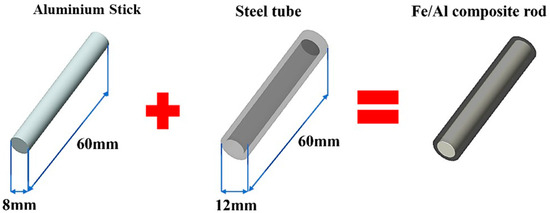
Figure 1.
Steel–aluminum composite structure schematic diagram.
The H-ECAP experiment was carried out using a self-designed compression mold, as shown in Figure 2. The mold material is 20CrMo steel, the mold parameters are φ = 120° and ψ = 30°, the channel diameter is 12 mm, and the channel length is 100 mm. The specific method is as follows: The low-carbon steel pipe is polished with sandpaper inside and outside and placed in the experimental mold together with the polished aluminum bar. The fastening bolt is tightened with the inner hexagonal wrench, and a normal force is applied to the mold through the fastening bolt, so that the mold can be tightened to reduce the experimental gap. MoS2 lubricant is used between the steel pipe and the mold, and the mold and the material are placed in the well-type heating furnace to be heated at 325 °C. The H-ECAP compression experiment is carried out on the microcomputer-controlled electronic universal testing machine at a pressing speed of 60 mm/min, and the sample is heat-treated at 520 °C after pressing.
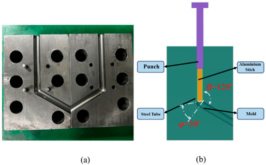
Figure 2.
Compression mold: (a) the physical drawing of the compression mold; (b) a three-dimensional drawing of the compression mold.
The Vickers hardness of the plate samples after multi-process treatment was tested by HVS-1000A automatic turret digital microhardness tester (Huayin Testing Instrument Co., Ltd., Laizhou City, China).
After the sample was cut, the parallelism of the opposite surface was strictly maintained, and the grinding and polishing treatment was carried out in turn. The test parameters were set to a load of 200 g and a holding time of 15 s. The indentation alignment was measured by uniform distribution and manually calibrated. Finally, the multi-point mean (experimental error ± 2 HV) was taken. The microstructure observation and composition analysis were completed by QUANTA FEG 650 (FEI, Hillsboro, OR, USA) scanning electron microscope and Oxford EDS spectrometer (Oxford, UK).
The sample was mirror polished and fixed on the vacuum stage with conductive adhesive. The vacuum environment was maintained throughout the process to avoid probe oxidation and data distortion. The phase identification (XRD) was performed using a D8 ADVANCE X-ray diffractometer (Bruker, Karlsruhe, Germany).
The original, extruded, and aged samples were scanned at a 20–90° wide angle, and the data were analyzed by Jade-6.5 software. Before the EBSD test, the sample was polished to a mirror surface by mechanical polishing, and then, the sample was electropolished by AC2 electrolyte under 20 V voltage (0.2–0.3 A current) for 100 s. The system was stabilized at −20 °C by liquid nitrogen temperature control. After polishing, the sample was washed with alcohol immediately to avoid surface oxidation.
3. Results
3.1. SEM and EDS Analysis
Figure 3 is the microscopic characterization (200×/500×/1000×) of the bonding layer under different ECAP passes combined with Nano Measurer quantitative analysis. The results show that the thickness of the interface layer decreases exponentially with the increase in the ECAP passes. The thickness of the interface layer is 29.98 μm for one pass, 23.74 μm for two passes, 7.84 μm for three passes, and only 7.78 μm for four passes. The intermetallic compound layer gradually thins. A characteristic tongue-like structure was formed on the iron matrix side, as shown in Figure 3f. The interface morphology on the aluminum matrix side changed from serrated to flat, and the original microcracks were completely healed after multi-pass pressing. This interface optimization is derived from the unique thermal-mechanical coupling effect of H-ECAP. The shear stress of one pass promotes the oxide layer to break and form a microcrack network. The subsequent ECAP passes drive the directional migration of Al atoms along the crack channel through the synergistic effect of dynamic recrystallization and interface diffusion.
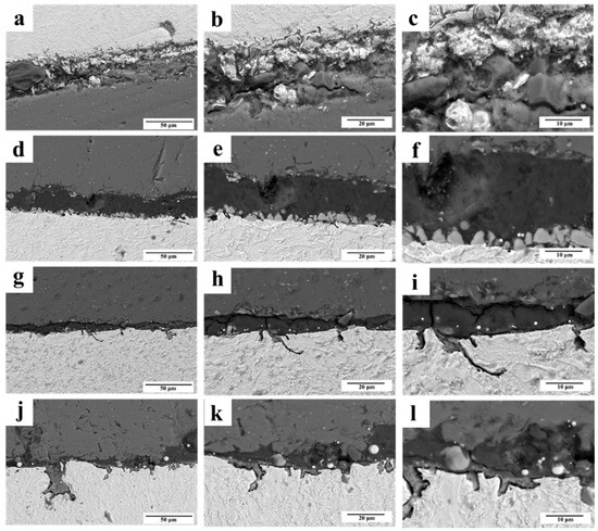
Figure 3.
Bond layer scanning diagram under different ECAP passes: (a–c) 1 pass; (d–f) 2 passes; (g–i) 3 passes; (j–l) 4 passes.
Due to the significant physical/chemical differences between Fe and Al components (such as thermal expansion coefficient mismatch, crystal structure incompatibility, etc.), the interface region is prone to induced residual stress concentration effects. Driven by thermodynamics, the Fe-Al elements undergo a violent solid-state diffusion reaction to form a brittle intermetallic compound (IMC) phase dominated by Fe2Al and FeAl. Its high hardness and low toughness significantly weaken the mechanical bearing capacity of the interface. The macro distribution trend of elements is obtained by surface scanning, as shown in Figure 4. Figure 4a shows the element distribution map of the one-pass sample. Al (cyan), Fe (red), O (green), and C (yellow) show competitive distribution characteristics in the interface region: Al element diffuses gradiently from the aluminum matrix to the iron side, while Fe element diffuses reversely, but the penetration depth is shallow. Significant Fe-Al interdiffusion was observed in the interfacial transition zone, confirming that the grain boundary activation effect caused by severe plastic deformation can significantly increase the atomic mobility. With the increase in ECAP passes, the concentration of oxygen at the interface decreases monotonously, which is due to the mechanical peeling effect of shear strain on the surface oxide layer and the continuous exposure of the new metal surface.
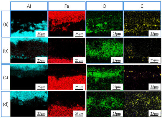
Figure 4.
Scanning diagram of bonding layer under different ECAP passes: (a) 1 pass; (b) 2 passes; (c) 3 passes; (d) 4 passes.
The element diffusion behavior characteristics of the Al/Fe interface bonding zone were systematically characterized by line scanning energy spectrum (EDS) technology, as shown in Figure 5. The concentration gradient distribution curves of Al and Fe elements clearly reveal the atomic migration law across the interface region: For one pass, as shown in Figure 5a, the concentration curves of Al and Fe show significant fluctuation characteristics, indicating that there is an accumulation of insufficiently combined metal fragments at the interface, which is directly related to the interface crushing effect in the initial pressing stage. With the increase in ECAP passes, as shown in Figure 5b–d, the element distribution gradually shows gradient diffusion characteristics, and the concentration curve shows an exponential decay trend from the matrix to the interface, which conforms to the solid-state diffusion dynamics. Energy spectrum analysis further confirmed the typical composition characteristics of the Fe2Al5 phase (Fe:Al = 2:5 at %) in the central region of the interface, and its serrated morphology was closely related to the dislocation slip mechanism induced by shear deformation. Combined with the analysis of the Fe-Al binary phase diagram, the interface reaction layer is mainly composed of the Fe2Al5 intermetallic compound on the side of the iron matrix and α (Al)/FeAl3 dual-phase structure on the side of the aluminum matrix. This dynamic redistribution process of elements driven by strain accumulation effectively promotes the directional migration of interface atoms and finally forms a dense metallurgical bonding interface. The effective bonding area presents a typical ‘X‘-shape element interlocking feature [23], indicating that a continuous brittle intermetallic compound layer is not formed.
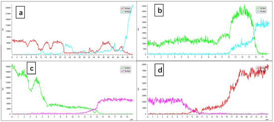
Figure 5.
Combined layer line scanning under different ECAP passes: (a) 1 pass; (b) 2 passes; (c) 3 passes; (d) 4 passes.
Through EDS point scanning and XRD phase analysis, Figure 6 systematically characterizes the characteristics of the steel–aluminum composite interface by XRD analysis. The results show that there are Fe2Al5, Fe, Al, and Al2O3 phases. Figure 7 shows the scanning characteristics of element distribution points in typical regions after ECAP extrusion for 1–4 passes. The quantitative analysis data (Table 3, Table 4, Table 5 and Table 6) show that the elemental composition of the interface area is mainly the Fe and Al matrix; according to the Al-Fe phase diagram, the reaction layer is mainly composed of FeAl3 and Fe2Al5 intermetallic compounds. When the steel plate interacts with semi-solid Al by diffusion, the FeAl3 phase is initially formed. With the increase in Al content at the interface, the Fe2Al5 phase is gradually formed. The distribution of this element is consistent with the evolution trend of intermetallic compounds detected by XRD, which confirms that the steel–aluminum interface is dominated by Fe-Al intermetallic compounds, and a variety of impurity phases coexist.
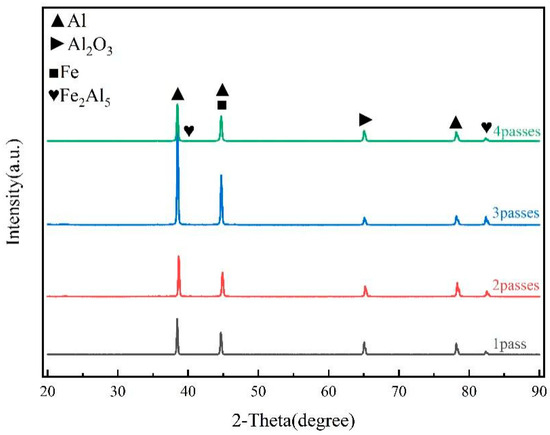
Figure 6.
XRD patterns of different ECAP passes.
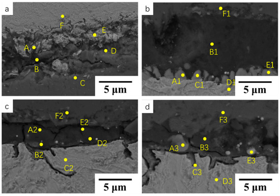
Figure 7.
Scanning images of each part under different ECAP passes: (a) 1 pass; (b) 2 passes; (c) 3 passes; (d) 4 passes.
Table 3.
Elemental composition in Figure 7a.
Table 4.
Elemental composition in Figure 7b.
Table 5.
Elemental composition in Figure 7c.
Table 6.
Elemental composition in Figure 7d.
3.2. EBSD Characterization
The microstructural characterization based on electron backscatter diffraction (EBSD), as shown in Figure 8a–d, systematically revealed the microstructural evolution of low-carbon steel during ECAP. After one pass of deformation, typical shear bands were formed in the transverse (TD) direction, and the grains showed disordered orientation distribution characteristics, showing a multi-color hybrid gradient color morphology, indicating that dislocation slip and crystal rotation caused by large plastic deformation led to the formation of an intragranular orientation gradient. The grains, after severe deformation at 325 °C hot pressing, did not coarsen significantly and still maintained their submicron size and non-equiaxed characteristics. As the ECAP passes increased to four passes, the original equiaxed grains underwent significant structural differentiation, forming a bimodal structure composed of elongated coarse grains and ultrafine equiaxed grains. At the same time, the grain orientation showed a clear preferential concentration trend. From two passes—such as in Figure 8b—to 4 passes—such as in Figure 8d—the proportion of grains with easy slip orientation increased significantly. This may be due to the directional rotation mechanism of grains induced by the ECAP shear stress field. The grains with soft orientation preferentially underwent plastic deformation through dislocation slip, while the grains with hard orientation achieved orientation adjustment through grain boundary migration and dynamic recrystallization, and finally formed a deformed structure with significant texture characteristics.
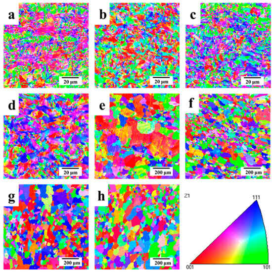
Figure 8.
IPF diagram of different ECAP passes. Steel side: (a) 1 pass, (b) 2 passes, (c) 3 passes, (d) 4 passes; aluminum side: (e) 1 pass, (f) 2 passes, (g) 3 passes, (h) 4 passes.
The grain evolution behavior of the 6061 aluminum alloy during equal-channel angular pressing (ECAP) is shown in Figure 8e–h. For one pass, as shown in Figure 8e, the microstructure shows multi-color orientation distribution characteristics, and the grain orientation is randomly distributed between (red) and (green), without a significant preferred orientation. This orientation dispersion phenomenon stems from the proliferation of dislocation defects and the synergistic rotation of crystals caused by large plastic deformation, resulting in the formation of orientation gradient regions (gradient color morphology) inside the grains. Although the initial orientation of the aluminum and steel matrix is disordered, the face-centered cubic structure of aluminum endows it with more active multi-slip system characteristics, which makes the atomic rearrangement mechanism show different characteristics. With the increase in processing passes, such as in Figure 8f–h, the grain rotation process dominated by shear stress significantly improves the orientation concentration through the synergistic effect of slip and twinning and finally forms a deformation texture with a specific preferred orientation. This orientation evolution is closely related to the high symmetry and low stacking fault energy characteristics of the aluminum crystal structure, which reflects the dynamic recrystallization behavior different from that of the steel matrix.
After one pass of deformation on the steel side, as shown in Figure 9a,a′, the low-angle grain boundaries (2–15°, green area) occupy a large number of observable proportions. As the ECAP pass increases to four passes, as shown in Figure 9b–d,b′–d′, the proportion does not show significant fluctuations, indicating that the subgrain boundaries formed by dislocations through slip/climb mechanisms are in a dynamic equilibrium state. The proportion of high-angle grain boundaries (>15°, red region) increases monotonously with the accumulation of deformation, from 31.2% of one pass to 32.1% of two passes, to 29.1% of three passes, and to 34.6% of the last four passes. This evolution is due to the dislocation proliferation–interaction mechanism induced by the strong shear stress of ECAP. The dislocation cell structure gradually evolves into subgrain boundaries after multi-pass deformation and finally transforms into stable high-angle grain boundaries through lattice rotation. At the same time, the dynamic recrystallization process triggered by hot pressing at 325 °C continues to generate new high-angle grain boundaries, further strengthening this trend. The fluctuation and rise characteristics of HABS value are coupled with the evolution law of grain boundary structure, which reveals the microscopic mechanism of the gradual reconstruction of the material grain boundary system in the direction of large angles under the synergistic effect of plastic deformation and thermal activation.
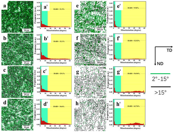
Figure 9.
Grain boundary structure diagram of different ECAP passes at different angles. Grain boundary ratio diagram. Steel side: (a) 1 pass, (b) 2 passes, (c) 3 passes, (d) 4 passes; aluminum side: (e) 1 pass, (f) 2 passes, (g) 3 passes, (h) 4 passes. Grain boundary ratio diagram: steel side (a′–d′), aluminum side (e′–h′). 2–15° (green), >15° (black).
The proportion of low-angle grain boundaries (2–15°, green area) measured by aluminum is relatively low in one pass as shown in Figure 9e,e′, but it shows a non-linear evolution with the increase in deformation passes: the proportion decreases significantly in two passes (Figure 9f,f′) and gradually increases from three passes (Figure 9g,g′) to four passes (Figure 9h,h′). This phenomenon is attributed to the dynamic recrystallization behavior of the aluminum alloy. The initial recrystallization process quickly consumes the low-angle grain boundaries, and the subgrain boundary structure is reformed by the synergistic effect of dislocation proliferation and slip in the subsequent passes. The HABS value of high-angle grain boundaries (>15°, red region) showed significant fluctuation characteristics, from 9.96% in one pass to 32.52% in two passes, and it then rose to 54.94% in three passes and finally to 63.76% in four passes. This evolution law is due to the unique deformation mechanism of the face-centered cubic structure. In the initial stage, dynamic recrystallization forms a large number of new high-angle grain boundaries. In the middle stage, grain merging and orientation coordination lead to a decrease in the proportion. In the later stage, continuous deformation and recrystallization synergistically promote the secondary increase in high-angle grain boundaries.
The correlation between dislocation density and grain boundary evolution during ECAP on the steel side is shown in Figure 10a,b, based on the analysis of the nuclear mean orientation difference (KAM) based on electron backscatter diffraction (EBSD). The microstructure analysis shows that the grains of the ECAP sample show significant directional characteristics, and its internal structure consists of two typical regions: the low-angle grain boundary (LAGB, green line) densely distributed inside the slender grains, and the other is the recrystallized grains with the high-angle grain boundary (HAGB, black line). The dislocation density shows non-uniformity in the spatial distribution—some areas have low dislocation density due to sufficient dynamic recrystallization, while the incomplete recrystallization area still maintains a high dislocation density state. With the increase in ECAP passes, the proportion of green area (LAGB) gradually decreases, which is attributed to the enhanced dislocation recovery effect during dynamic recrystallization. During one-pass deformation, high-strain load leads to rapid dislocation proliferation and insufficient recovery, forming significant dislocation accumulation. In the subsequent passes, under the synergistic effect of high-temperature conditions and the cumulative thermal activation effect, the dislocations are continuously reduced through the slip/climb mechanism, which effectively alleviates the work-hardening effect. The KAM distribution map further shows that the high value area of dislocation density is mainly located near the LAGB inside the grains, and the overall distribution shows a trend of spatial homogenization. This feature is highly consistent with the evolution law of LAGB to HAGB transition in grain boundary statistical results, as in Figure 10a′–d′.
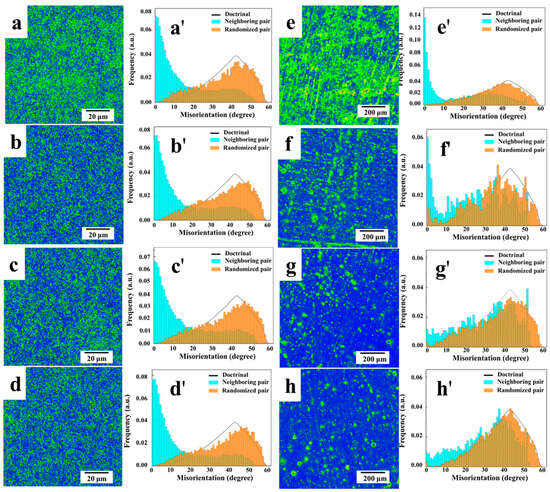
Figure 10.
KAM diagram of steel side in different ECAP passes: (a) 1 pass, (b) 2 passes, (c) 3 passes, (d) 4 passes; the distribution map of misorientation angle: (a′) 1 pass; (b′) 2 passes; (c′) 3 passes; (d′) 4 passes. KAM diagram of aluminum side in different ECAP passes: (e) 1 pass, (f) 2 passes, (g) 3 passes, (h) 4 passes; the distribution map of misorientation angle: (e′) 1 pass; (f′) 2 passes; (g′) 3 passes; (h′) 4 passes.
The aluminum side is shown in Figure 10e–h. The microstructure characterization shows that the strong shear strain introduced by the ECAP process leads to a significant directional arrangement of grains, and a large number of low-angle grain boundary (LAGB) subgrains (green areas) are formed by dislocation slip and accumulation in one pass. With the increase in deformation amount, the subgrains are broken and reorganized under continuous shear strain and gradually transformed into a high-angle grain boundary (HAGB) structure through the dynamic recrystallization process, which effectively promotes dislocation annihilation and reduces local strain energy. Quantitative analysis shows that the proportion of green areas characterizing dislocation density decreases with the increase in passes, as shown in Figure 10e′–h′, which is attributed to the dislocation recovery effect of dynamic recrystallization under thermomechanical coupling. The dislocation recovery of the one-pass sample is incomplete due to insufficient deformation time, resulting in a significantly higher dislocation density in the LAGB region and causing work hardening. The distribution characteristics of KAM further indicate that the dislocation density shows a uniform distribution trend in space, and the high-density area is mainly concentrated at the LAGB network inside the grains, which is related to the formation mechanism of grain boundary statistical results and jointly confirms the microstructure evolution law of subgrain crushing–high angle grain boundary recombination during ECAP.
As shown in Figure 11a–d, a systematic analysis of the microstructural evolution based on multi-pass equal-channel angular pressing (ECAP) reveals the recrystallization kinetics during high-temperature plastic deformation in the steel. With increasing ECAP passes, the cumulative strain within the material rises significantly, inducing concurrent dynamic recovery and recrystallization. A quantitative statistical analysis of the microstructure indicates that the red regions in the figure represent substructures, the yellow regions correspond to recovered structures, and the blue regions signify recrystallized structures. Under the 325 °C ECAP condition, Figure 11a shows that substructures dominate (constituting the largest proportion), but a certain amount of recovered and recrystallized structures are still present. This indicates that plastic deformation is the primary mechanism at this temperature, accompanied by limited recovery and recrystallization processes. As the number of passes increases (Figure 11b–d), the proportion of recovered and recrystallized structures rises markedly. Quantitative data from Figure 11e demonstrate that the fraction of substructures gradually decreases from an initial 72.19% to 35.46%, while the fraction of recrystallized structures increases from 10.12% after one pass to 43.56% after four passes. This microstructural evolution is attributed to the coupling effect of the intense shear stress inherent in ECAP and thermal activation at the elevated temperature of 325 °C. On the one hand, the plastic deformation mechanism, dominated by grain boundary sliding and dislocation climb, promotes the gradual transformation of subgrain boundaries into high-angle grain boundaries (HAGBs). On the other hand, dynamic recrystallization facilitates grain reconstruction through the migration of HAGBs, effectively weakening the original deformation texture. From a thermodynamic perspective, the fine-grained structure, characterized by a high density of grain boundaries, provides ample pathways for thermal activation energy. This accelerates the processes of dislocation annihilation and lattice recovery. Furthermore, the cumulative thermal effect induced by multi-pass deformation leads to a continuous increase in grain boundary stored energy. This not only weakens grain boundary strength but also intensifies grain boundary diffusion and vacancy migration. Such changes in the micromechanisms significantly impact material properties. The weakening of grain boundaries and enhanced diffusion promote high-temperature creep behavior and increase the propensity for intergranular slip during subsequent processing. Concurrently, the accumulation of grain boundary stored energy with increasing passes causes a rapid decline in grain boundary strength relative to the matrix, substantially elevating the risk of intergranular fracture in high-temperature environments.
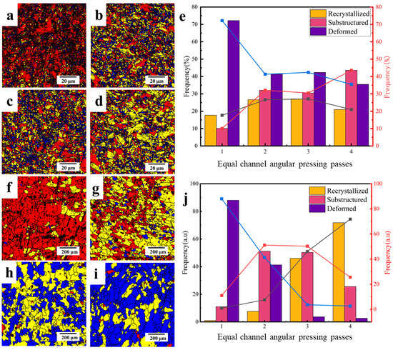
Figure 11.
Recrystallization diagram of different ECAP passes. Steel side (a–d): 1 pass; 2 passes; 3 passes; 4 passes. (e) Recrystallization proportion diagram of steel side. Aluminum measurement (f–i): 1 pass; 2 passes; 3 passes; 4 passes. (e) Steel side recrystallization ratio diagram. (j) Aluminum side recrystallization ratio diagram. Trend lines: Deformed (blue), Substructured (red), Recrystallized (black).
As shown in Figure 11f–i, the microstructural evolution of the aluminum side during multi-pass ECAP is systematically revealed using a three-color calibration system (red: deformed grains; yellow: recovered grains; blue: recrystallized grains). Following one pass in Figure 11f, deformed grains (red regions) dominate the microstructure. Under intense shear stress, coarse grains elongate along the shear direction, forming a characteristic banded structure. This process is accompanied by a sharp increase in the proportion of low-angle grain boundaries (LAGBs), as the coarse grains dissociate into subgrains bounded by these LAGBs. With increasing ECAP passes, significant microstructural transformation occurs. Quantitative data from Figure 11j show that the fraction of deformed grains decreases from 88.03% after one pass to 41.29% after two passes, while the proportion of recovered grains increases correspondingly. After four passes, the subgrains undergo continuous fragmentation and reorganization, initiating the formation of an equiaxed grain structure partially characterized by high-angle grain boundaries (HAGBs). However, the persistence of a certain proportion of LAGBs indicates incomplete recovery. By four passes in Figure 11i, the fraction of recrystallized grains (blue regions) increases markedly from 0.97% in one pass to 71.81%, achieving submicron grain refinement.
This microstructural evolution is fundamentally attributed to the dynamic recrystallization mechanism induced by cumulative strain. Severe shear deformation promotes the annihilation of substructures, while the continuous accumulation of intergranular misorientation drives the formation and migration of high-angle grain boundaries (HAGBs). Recrystallization nuclei reconstruct the lattice orientation through HAGB migration. This process effectively eliminates the original deformation texture and transforms the characteristic banded structure into a uniform equiaxed grain structure. Concurrently, the intragranular misorientation distribution significantly decreases, and microstructural homogeneity substantially improves, demonstrating the efficacy of the ECAP process in refining grains and homogenizing the microstructure of aluminum.
3.3. Hardness Analysis
Figure 12 quantitatively characterizes the microhardness distribution of samples processed with varying ECAP pass counts. Results demonstrate that as the number of ECAP passes increases from one to four, the microhardness of the steel matrix elevates from 222 HV to 271 HV, while the aluminum matrix hardness rises from 51.4 HV to 83.6 HV. Notably, the interfacial bonding layer exhibits the most pronounced enhancement, surging from 45.4 HV to 96.8 HV. This gradient strengthening phenomenon stems from deformation mechanisms inherent to ECAP processing: Firstly, accumulated shear strain undergoes geometric progression with each successive pass, inducing exponential dislocation accumulation within both steel and aluminum matrices. The resultant dislocation entanglement generates significant work hardening, substantially enhancing material strength. Secondly, grain refinement-induced boundary strengthening conforms to the Hall–Petch relationship. Steel-side grains transition from coarse-grained structures after one pass to submicron-scale microstructures following four passes, where the exponentially increased grain boundary density establishes effective “dislocation motion barriers”. Although the aluminum matrix experiences slight thermal-induced grain coarsening, its subgrain boundary density progressively intensifies with pass accumulation, further impeding dislocation glide. The exceptional hardness leap within the interfacial bonding layer arises from synergistic “strain concentration—elemental interdiffusion” mechanisms: During ECAP, interfacial regions become strain concentration zones due to deformation incompatibility between dissimilar matrices. The alternating shear stresses generated by Route C processing (180° billet rotation per pass) intensify dislocation pile-up and mutual interactions at the interface.
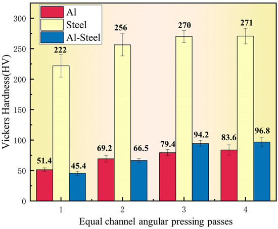
Figure 12.
Hardness diagram of each part of aluminum side in different pressing passes.
3.4. Room-Temperature Compressive Properties
As evident from Figure 13, the yield strength under room-temperature compression progressively increases from 361 MPa to 372.35 MPa as the number of ECAP passes rises from one to four, accompanied by concurrent enhancement in compressive strength. This phenomenon can be thoroughly elucidated through the core principles of ECAP: The ECAP die, configured with an inner channel angle of φ = 120° and an outer curvature angle of ψ = 30°, subjects the material to intense plastic deformation, approximating quasi-pure shear strain upon passage through the channel. According to the Segal strain formula, each additional pass induces linear growth in accumulated strain. This forces dislocations to continuously pile up at grain and subgrain boundaries, forming high-density networks. The resulting dislocation entanglement effect significantly increases slip resistance, generating work hardening. Concurrently, the intense shear deformation drives grain elongation along the shear direction, followed by fragmentation. The subsequent merging of subgrain boundaries forms HAGBs. The grain refinement-induced boundary strengthening adheres to the Hall–Petch relationship, further elevating strength. When employing Route C (180° billet rotation per pass), the alternating shear strain direction promotes more uniform stress distribution, mitigating interfacial stress concentration. Simultaneously, multi-pass processing facilitates the fragmentation of interfacial oxides and optimization of the bonding layer, thereby enhancing the degree of metallurgical bonding at the interface. This synergistic multi-mechanism process—encompassing cumulative strain accumulation, dislocation strengthening, grain refinement, and interfacial optimization—collectively drives the stepwise enhancement of material strength following multi-pass ECAP.
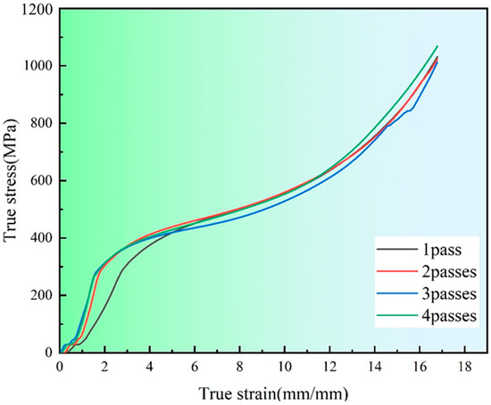
Figure 13.
Compression curves of different ECAP passes.
4. Conclusions
The present study systematically investigated the effects of equal-channel angular pressing (ECAP) on the microstructure, properties, and bonding characteristics of steel–aluminum composites, revealing the following comprehensive conclusions.
- Microstructure and properties of the steel side: With the increase in ECAP passes, the microstructure of the steel side was refined. The grain size of 1–4 passes decreased from 2.2 μm to 1.3 μm, and obvious shear bands and preferred orientation appeared. The large-angle grain boundaries increased, and the proportion of deformed microstructure decreased from 72.19% to 35.46%. After two passes, the grain refinement effect slowed down but still decreased, and the hardness increased from 222 HV to 271 HV.
- Changes in microstructure and properties of the aluminum side: One pass of the aluminum side is mainly composed of coarse grains and a small amount of fine equiaxed grains, and shear bands appear in two passes. The high-angle grain boundary increases from 9.96% to 63.76%, the grain size is refined from 59.3 μm to 28.2 μm, the recrystallized structure increases from 0.97% to 71.81%, and the hardness increases from 51.4 HV to 83.6 HV.
- With the increase in ECAP passes, the interface thickness of the bonding layer decreased from 29.98 μm to 7.78 μm, and the oxygen content decreased. Spot scanning and XRD analysis show that the bonding layer contains a small amount of matrix oxide, FeAl3, and Fe2Al5 phases in addition to the matrix.
Future research should expand the range of ECAP passes, conduct comprehensive mechanical tests, study process parameters, explore ECAP for functional composites, combine it with other techniques, and use advanced in situ methods to understand the process better and innovate composite applications.
Author Contributions
Conceptualization, J.X.; methodology, Y.L., B.C. and Y.F.; validation, W.L., H.S. and Y.F.; formal analysis, B.C., Y.F. and W.L.; investigation, B.C., Y.F. and H.S.; data curation, B.C., Y.F., W.L. and H.S.; writing—original draft preparation, Y.L., B.C. and Y.F.; writing—review and editing, Y.L. and B.C.; visualization, B.C., Y.F., W.L. and H.S.; supervision, J.X.; funding acquisition, J.X. All authors have read and agreed to the published version of the manuscript.
Funding
This research was funded by the Inner Mongolia Natural Science Foundation (2021MS05004) Projects of Basic Scientific Research Business Expenses of Universities Directly under the Inner Mongolia Autonomous Region (JY20220060) and the National College Student Innovation and Entrepreneurship Training Program (202510128004).
Data Availability Statement
The original contributions presented in this study are included in the article. Further inquiries can be directed to the corresponding authors.
Conflicts of Interest
The authors declare no conflict of interest.
References
- Winkler, L.; Pearce, D.; Nelson, J.; Babacan, O. The effect of sustainable mobility transition policies on cumulative urban transport emissions and energy demand. Nat. Commun. 2023, 14, 2357. [Google Scholar] [CrossRef]
- Yang, J.; Oliveira, J.P.; Li, Y.; Tan, C.; Gao, C.; Zhao, Y.; Yu, Z. Laser techniques for dissimilar joining of aluminum alloys to steels: A critical review. J. Mater. Process. Technol. 2022, 301, 117443. [Google Scholar] [CrossRef]
- Cho, Y.R. Clad metals: Fabrication, properties, and applications. Metals 2021, 11, 1186. [Google Scholar] [CrossRef]
- Tavakoli, A.M.; Nami, B.; Malekan, M.; Khoubrou, I. Influences of coating type on microstructure and strength of aluminum–steel bimetal composite interface. Int. J. Met. 2022, 16, 689–698. [Google Scholar] [CrossRef]
- Liu, W.; Wang, N.; Wang, T.; Chen, Z. Study on the Influence of Prefabricated Aluminum Layer Technology on the Properties of Corrugated Interface Steel/Aluminum/Aluminum Alloy Composite Panel. J. Mater. Eng. Perform. 2025, 34, 6148–6158. [Google Scholar] [CrossRef]
- Carvalho, G.H.S.F.L.; Galvão, I.; Mendes, R.; M. Leal, R.; Loureiro, A. Aluminum-to-steel cladding by explosive welding. Metals 2020, 10, 1062. [Google Scholar] [CrossRef]
- Chi, P.; Xiong, W.; Mu, X.; Zhu, B.; Zhou, J.; Bi, X. Experimental test and simulation calculation of fatigue properties of aluminum–titanium-steel explosive welded connector under tension-compression cyclic loading. J. Mater. Res. Technol. 2023, 24, 4678–4684. [Google Scholar] [CrossRef]
- Carvalho, G.; Galvão, I.; Mendes, R.; Leal, R.; Loureiro, A. Explosive welding of aluminium to stainless steel using carbon steel and niobium interlayers. J. Mater. Process. Technol. 2020, 283, 116707. [Google Scholar] [CrossRef]
- Zhou, Q.; Liu, R.; Chen, P.; Zhu, L. Microstructure characterization and tensile shear failure mechanism of the bonding interface of explosively welded titanium-steel composite. Mater. Sci. Eng. A 2021, 820, 141559. [Google Scholar] [CrossRef]
- Ren, Z.; Guo, X.; Liu, X.; Ma, X.; Jiang, S.; Bian, L.; Wang, T.; Huang, Q. Effect of pulse current treatment on interface structure and mechanical behavior of TA1/304 clad plates. Mater. Sci. Eng. A 2022, 850, 143583. [Google Scholar] [CrossRef]
- Cheng, Y.; Liu, W.; Wang, T.; Li, T.; Huang, Q. Study on the effects of initial temperature and thickness ratio of component metals on the preparation of aluminum/steel clad plates by the new different temperature rolling method. J. Manuf. Process. 2023, 95, 229–241. [Google Scholar] [CrossRef]
- Šlapáková, M.; Kihoulou, B.; Veselý, J.; Minárik, P.; Fekete, K.; Knapek, M.; Králík, R.; Grydin, O.; Stolbchenko, M.; Schaper, M. 3D-structure of intermetallic interface layer in Al–steel clad material. Vacuum 2023, 212, 112043. [Google Scholar] [CrossRef]
- Saxena, K.K.; Gupta, A. Effect of processing parameters on equal-channel angular pressing of aluminum alloys: An overview. Mater. Today Proc. 2021, 45, 5551–5559. [Google Scholar] [CrossRef]
- Awasthi, A.; Rao, U.S.; Saxena, K.K.; Dwivedi, R.K. Impact of equal channel angular pressing on aluminium alloys: An overview. Mater. Today Proc. 2022, 57, 908–912. [Google Scholar] [CrossRef]
- Rezaei, A.; Mahmudi, R.; Cayron, C.; Logé, R. Simple shear extrusion versus equal channel angular pressing: A comparative study on the microstructure and mechanical properties of an Mg alloy. J. Magnes. Alloys 2023, 11, 1769–1790. [Google Scholar] [CrossRef]
- Agarwal, K.M.; Tyagi, R.K.; Choubey, V.; Saxena, K.K. Mechanical behaviour of Aluminium Alloy AA6063 processed through ECAP with optimum die design parameters. Adv. Mater. Process. Technol. 2022, 8, 1901–1915. [Google Scholar] [CrossRef]
- Klu, E.E.; Song, D.; Li, C.; Wang, G.; Gao, B.; Ma, A.; Jiang, J. Achieving ultra-fine grains and high strength of Mg–9Li alloy via room-temperature ECAP and post rolling. Mater. Sci. Eng. A 2022, 833, 142371. [Google Scholar] [CrossRef]
- Park, K.; Kim, D.; Kim, K.; Kwon, H. Aluminum/stainless steel clad materials fabricated via spark plasma sintering. Materials 2020, 13, 239. [Google Scholar] [CrossRef]
- Deng, Z.J.; Yu, C.; Xiao, H. Effect of surface treatment on bonding strength of hot rolled steel aluminum clad plate. In IOP Conference Series: Materials Science and Engineering; IOP Publishing: Bristol, UK, 2022; Volume 1270, p. 012016. [Google Scholar]
- Li, R.; Yuan, T.; Liu, X.; Zhou, K. Enhanced atomic diffusion of Fe–Al diffusion couple during spark plasma sintering. Scr. Mater. 2016, 110, 105–108. [Google Scholar] [CrossRef]
- Basantia, S.K.; Bhattacharya, A.; Khutia, N.; Das, D. Plastic behavior of ferrite–pearlite, ferrite–bainite and ferrite–martensite steels: Experiments and micromechanical modelling. Met. Mater. Int. 2021, 27, 1025–1043. [Google Scholar] [CrossRef]
- Kumar, A.; Dutta, A.; Makineni, S.K.; Herbig, M.; Petrov, R.; Sietsma, J. In-situ observation of strain partitioning and damage development in continuously cooled carbide-free bainitic steels using micro digital image correlation. Mater. Sci. Eng. A 2019, 757, 107–116. [Google Scholar] [CrossRef]
- Dai, G.; Liu, Y.; Chen, K.; Liu, W.; Wang, T.; Huang, Q. Effect of cumulative deformation and interlayer mechanical properties on bonding strength of corrugated interface steel/aluminum composite plate. J. Manuf. Process. 2023, 103, 78–89. [Google Scholar] [CrossRef]
Disclaimer/Publisher’s Note: The statements, opinions and data contained in all publications are solely those of the individual author(s) and contributor(s) and not of MDPI and/or the editor(s). MDPI and/or the editor(s) disclaim responsibility for any injury to people or property resulting from any ideas, methods, instructions or products referred to in the content. |
© 2025 by the authors. Licensee MDPI, Basel, Switzerland. This article is an open access article distributed under the terms and conditions of the Creative Commons Attribution (CC BY) license (https://creativecommons.org/licenses/by/4.0/).