Article

Improving the Wear Properties of Ni Matrix Composites Containing High-Speed Steel Particles

Department of Metal Science and Materials Technologies, Kielce University of Technology, 1000-lecia PP Ave. 7, 25-314 Kielce, Poland
Metals 2025, 15(7), 772; https://doi.org/10.3390/met15070772
Submission received: 10 June 2025 / Revised: 30 June 2025 / Accepted: 8 July 2025 / Published: 8 July 2025
(This article belongs to the Section Metal Matrix Composites)

Abstract

Nickel matrix composites reinforced with T15 high-speed steel (HSS) were prepared using powder metallurgy techniques. A systematic investigation was conducted into the effect of CeO2, MoS2, and graphite additives on the tribological properties of the composites. The results show that when T15 HSS particles are added, nickel grains do not grow as much as they do in pure sintered nickel. It was also observed that the T15 HSS particles were diffusion-bonded to the nickel matrix after sintering. The highest relative density after sintering is obtained for composites containing graphite, but the maximum hardness of 243 HV can be achieved for composites containing 2% of CeO2, which is about 16% higher than that of the Ni-T15 HSS composite. The wear rate of Ni-T15 HSS composites reduces from 3.4782 × 10⁻⁷ cm3/N∙m to 2.0222 × 10⁻⁷ cm3/N∙m as the content of CeO2 rises from 0 wt.% to 2 wt.%. The wear mechanisms of composites with MoS2 or graphite are abrasive wear and adhesive wear. The introduction of CeO2 enhances the hardness of the investigated composites to the highest degree, leading to a change in the wear mechanism of the composites to slight abrasive wear. The addition of CeO2 can effectively optimize the tribological properties of Ni-T15 HSS composites.

Graphical Abstract

1. Introduction

As industries have grown, the energy used because of parts wearing out has become a worldwide problem; hence, we need composite materials [1,2]. Powder metallurgy (PM) is generally considered the most common way to make metal matrix composites (MMCs) [3]. One benefit of PM over casting is that it gives much finer control over the microstructure and spread of the reinforcing material because diffusion in solid materials is very important in how the bonds between particles form and grow [4]. The size of the particles and how much reinforcement is used greatly affect how strong the composite materials are [5]. Properly reinforced metal matrix composites have high stiffness, remarkable strength, high hardness, and excellent wear resistance, as well as provide much better surface quality than most standard materials used in engineering [1,3,5,6,7]. Nickel matrix composites (NMCs) work well for aerospace and military uses because they are mechanically strong and resist wear [8]. It is known that the extent of improvement of nickel matrix composites (NMCs) depends mostly on the qualities of the reinforcing material and how well they stick to the nickel. Ceramic particles such as borides, carbides, zirconia, and oxides, such as Al2O3 and ThO2, are thought to work well for strengthening nickel matrix composites [9,10,11,12,13]. Unfortunately, due to their poor wettability and the significant discrepancy in the thermal expansion coefficient between ceramic materials and the nickel matrix, sintered composite materials lack toughness and strength. It has been shown [14] that nickel composites containing transition-metal dichalcogenides (WS2 and MoS2) and alkaline halides (CeF2, BaF2, and CaF2) have been extensively used for reducing friction and wear at ambient and high-temperature testing conditions. Also, the introduction of an appropriate amount of rare earth elements is an effective way to improve the friction and wear performance of composite materials [15]. Li et al. [15] prepared nickel matrix composites containing silver, MoS2, and CeO2 using the powder metallurgy method. The addition of CeO2 reduced wear rate at high temperatures, which was attributed to the fact that rare earth compounds contribute to the formation of a smooth layer that improves wear resistance at high temperatures. To increase interfacial bonding and produce the high strength and toughness of composite materials, metal particle-reinforced metal matrix composites have garnered attention [6,15,16,17]. Even so, there are not many studies about NMCs that are strengthened using metal particles. Most of the studies that do exist are about making nickel matrix composites with soft metals like gold and silver, which are used as solid lubricants [10]. There is a lack of scientific work on the production of sintered composites using a nickel matrix reinforced with steel particles, which are characterized by high hardness and resistance to abrasive wear. The novelty of this work is in-depth insight into the role of rare earth oxides and solid lubricants in optimizing the mechanical and frictional performance of nickel matrix composites. In this study, Ni high-speed steel (HSS) particle composites with different CeO2, MoS2, and graphite contents were fabricated using the PM method. The effect of CeO2, MoS2, and graphite on the tribological properties of Ni HSS composites was investigated by analyzing the microstructure, hardness, coefficient of friction, and wear rate of the composites with different contents of CeO2, MoS2, and graphite. The wear mechanism of the composites was elucidated by observing the morphology of worn surfaces. The research results obtained allowed for the scientific gap that was identified during the literature study to be filled.

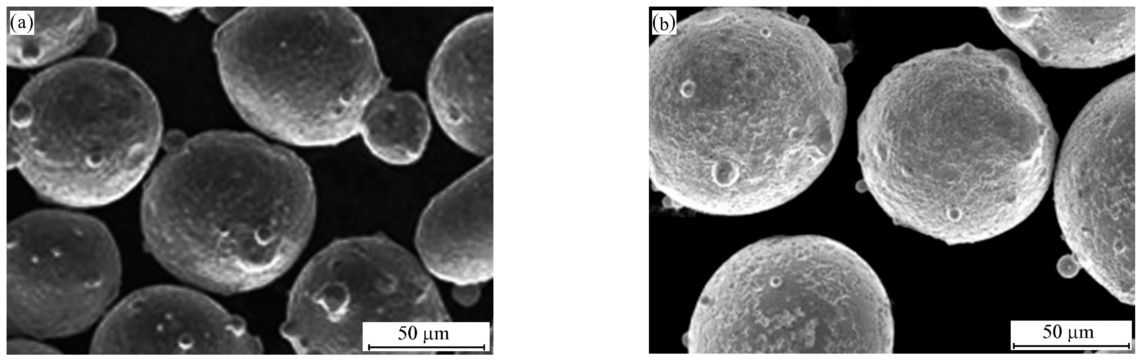
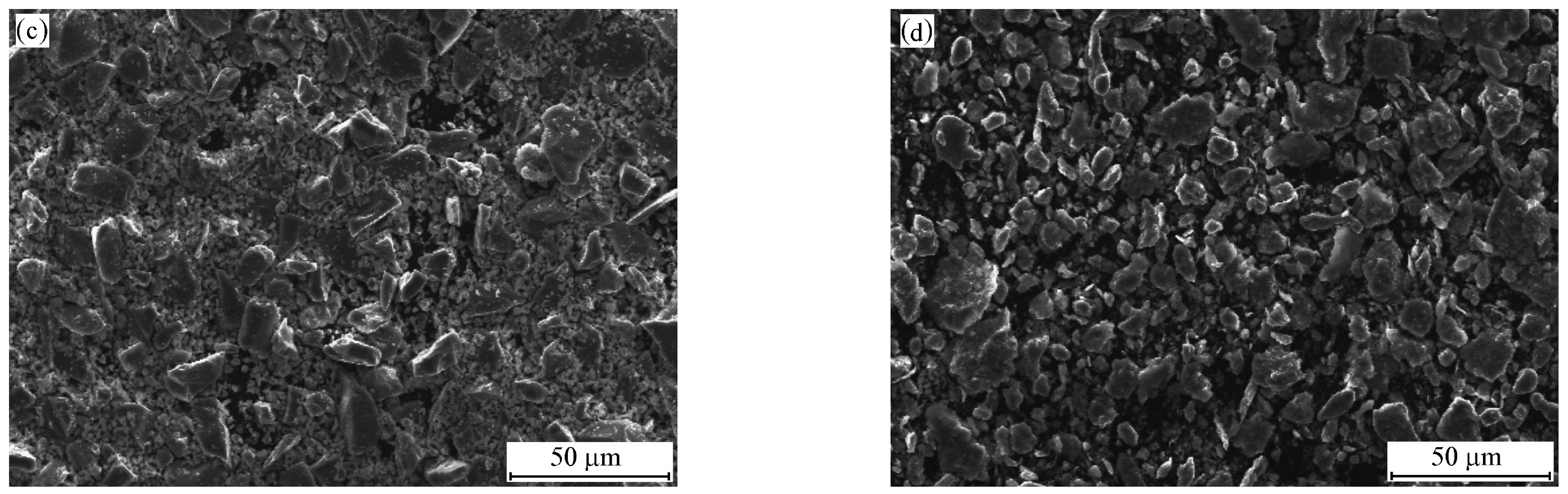
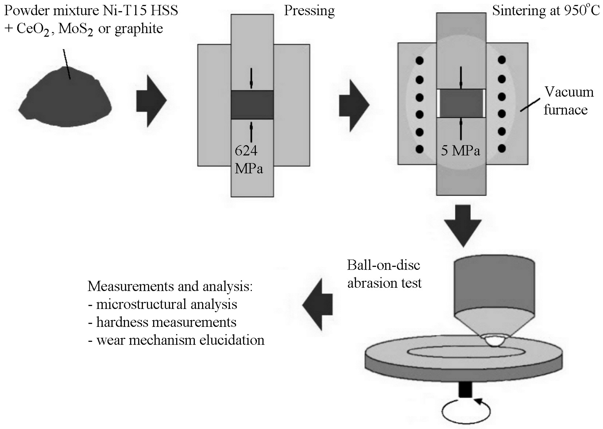
2. Materials and Methods

Ni-HSS composites were fabricated using commercially available nickel (99.75% of Ni, 0.1% of Fe, 0.08% of Cu, 0.05% of Zn, 0.02% of Co), T15 high-speed steel (1.5% of C, 0.4% of Si, 0.4% of Mn, 4.5% of Cr, 0.5% of Mo, 5.0% of V, 12.5% of W, 4.75% of Co, and the rest of Fe), CeO2, MoS2, and graphite powders by sintering. Nickel powder was used as the main material, and T15 HSS powder was added as the reinforcement. CeO2, MoS2, and graphite (1 μm particle size) powders with melting temperatures of 2400, 1185, and 3600 °C, respectively, were used as additives to reduce abrasive wear. The atomized nickel powder had particle sizes between 40 and 70 μm, while the atomized high-speed steel had particle sizes between 50 and 120 μm. The shapes and arrangements of the powder particles used in the experiments are shown in Figure 1.
Powder mixtures with constant amounts of T15 HSS (20 wt.%), pure nickel, and different amounts of CeO2, MoS2, and graphite powders were mixed together in a steel container. This was performed using a rotary mill. The powders were milled for 1 h. The ratio of the balls to the powder (BPR) was 10:1, and the rotation speed was 120 rpm. The composition of the powder mixtures is listed in Table 1 with the following sample codes: NS (Ni-20%T15 HSS), NSC1 (Ni-20%T15 HSS-1%CeO2), NSC2 (Ni-20%T15 HSS-2%CeO2), NSM1 (Ni-20%T15 HSS-1%MoS2), NSM2 (Ni-20%T15 HSS-2%MoS2), NSG0.5 (Ni-20%T15 HSS-0.5%graphite), and NSG1 (Ni-20%T15 HSS-1%graphite).
The specimens, which were 35 mm in diameter, 10 mm high, and made from pure nickel powder (used as a comparative sample) as well as the prepared powder mixtures, were subjected to single-track pressing on an Amsler hydraulic press. The compaction pressure used was 624 MPa. The green compacts were sintered at 950 °C in a vacuum furnace for 2 h by applying a uniaxial pressure of 5 MPa, and then the furnace was cooled. The parameters of the sintering process of the Ni–T15 HSS composites were optimized during previous studies described in [17]. The mass of the samples was quantified using an electronic microbalance WPA120 (Radom, Poland) with a precision of 10−4 g. The density was determined by weighing the specimens in air and water in line with the EN ISO 2738:2001 standard [18]. The abrasion resistance tests of the fabricated specimens were conducted using an Anton Paar TRB3 ball-on-disk tribometer (Graz, Austria) according to the requirements of the ASTM G 99 standard [19]. The sliding track was set at a 10 mm radius away from the disk center. The following parameters were set for the abrasive wear test: (a) a friction pair (a 100Cr6 hardened steel ball 10 mm in diameter and a disk made of the investigated material), (b) a load of 5 N, (c) a sliding velocity of 0.1 m/s, (d) a friction path distance of 1000 m, (e) a humidity level of 46%, (f) an ambient temperature of 22 °C, and (g) atmospheric pressure of 1002 hPa. The abrasive wear resistance tests were carried out under dry friction conditions. The samples were weighed both before and after the tribological tests to determine weight loss. In order to determine the depth and amount of wear marks on the composites, a three-dimensional profilometer Leica DCM8 was used (Wetzlar, Germany). A schematic diagram of the experimental procedure is shown in Figure 2.
Samples for microscopic examination were cut using a low-speed diamond saw and embedded in quick-setting resin. Then, they were ground using sandpaper with a grit of up to 1200 and polished with a diamond suspension (1 mm). The microstructural analyses of the metallographic specimens were performed using a JEOL JMS 5400 scanning electron microscope (SEM) (Tokyo, Japan) and a Nikon Eclipse MA200 optical microscope (OM) (Tokyo, Japan). Before the samples were examined with the optical microscope, they were etched using a solution of 2 mL HNO3 and 100 mL C2H5OH. The hardness of the materials was measured using the Vickers hardness method HV30 (294 N) in accordance with the EN ISO 6507-1:2023 standard [20]. The reported data for all tests are the average values of the three tested specimens.

3. Results and Discussion

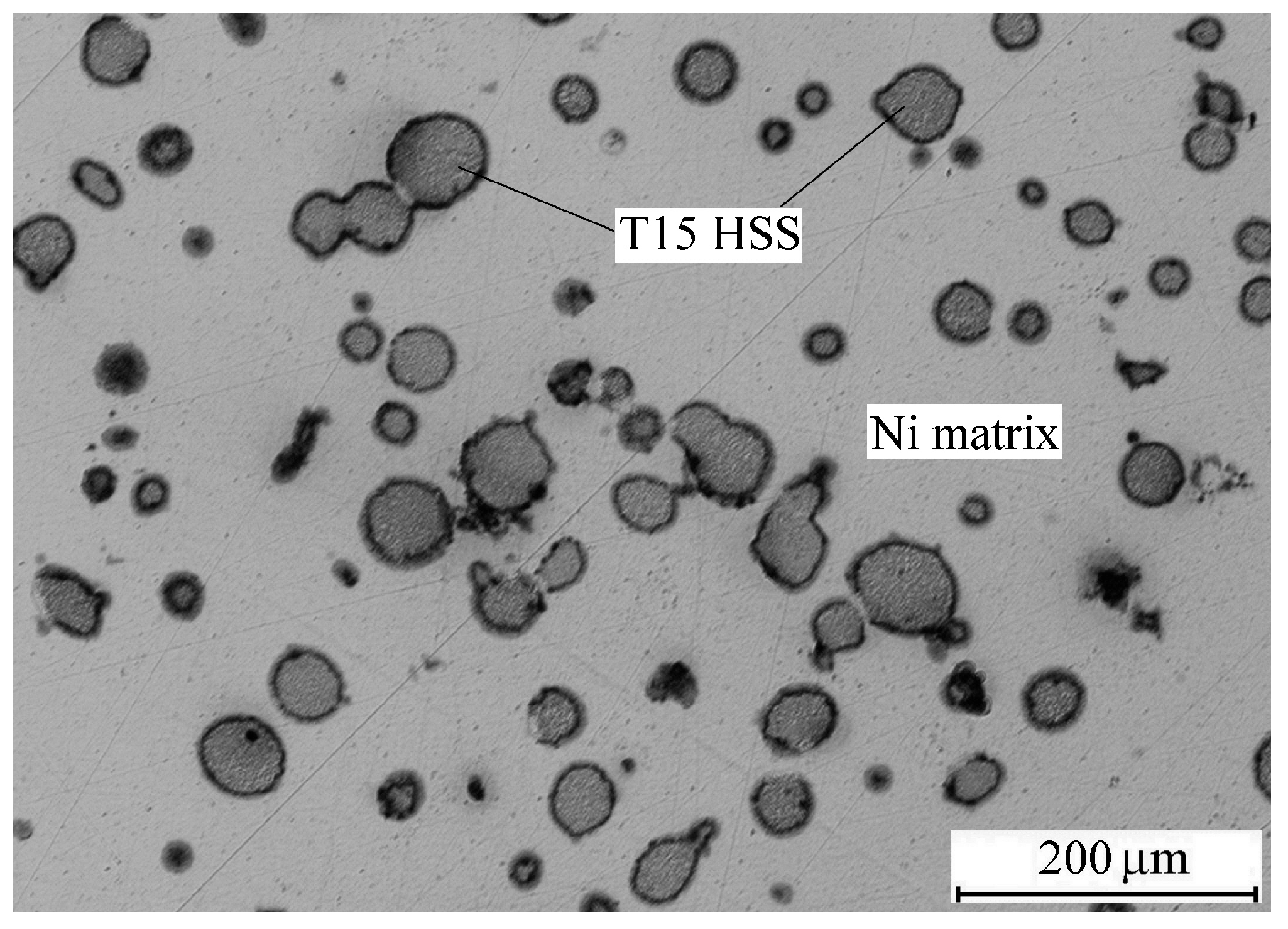
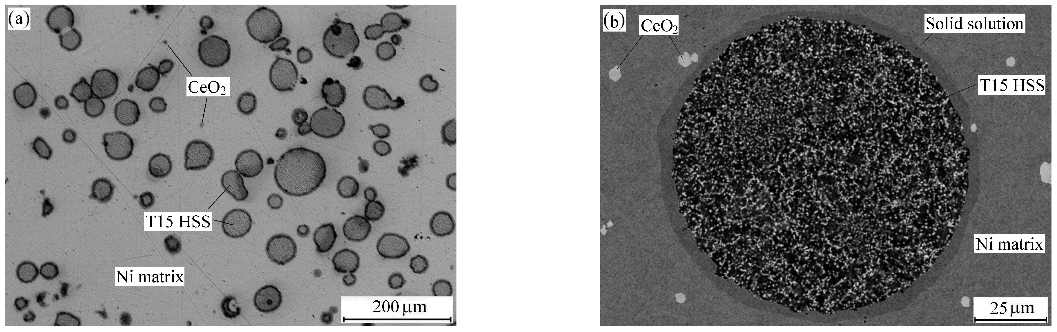
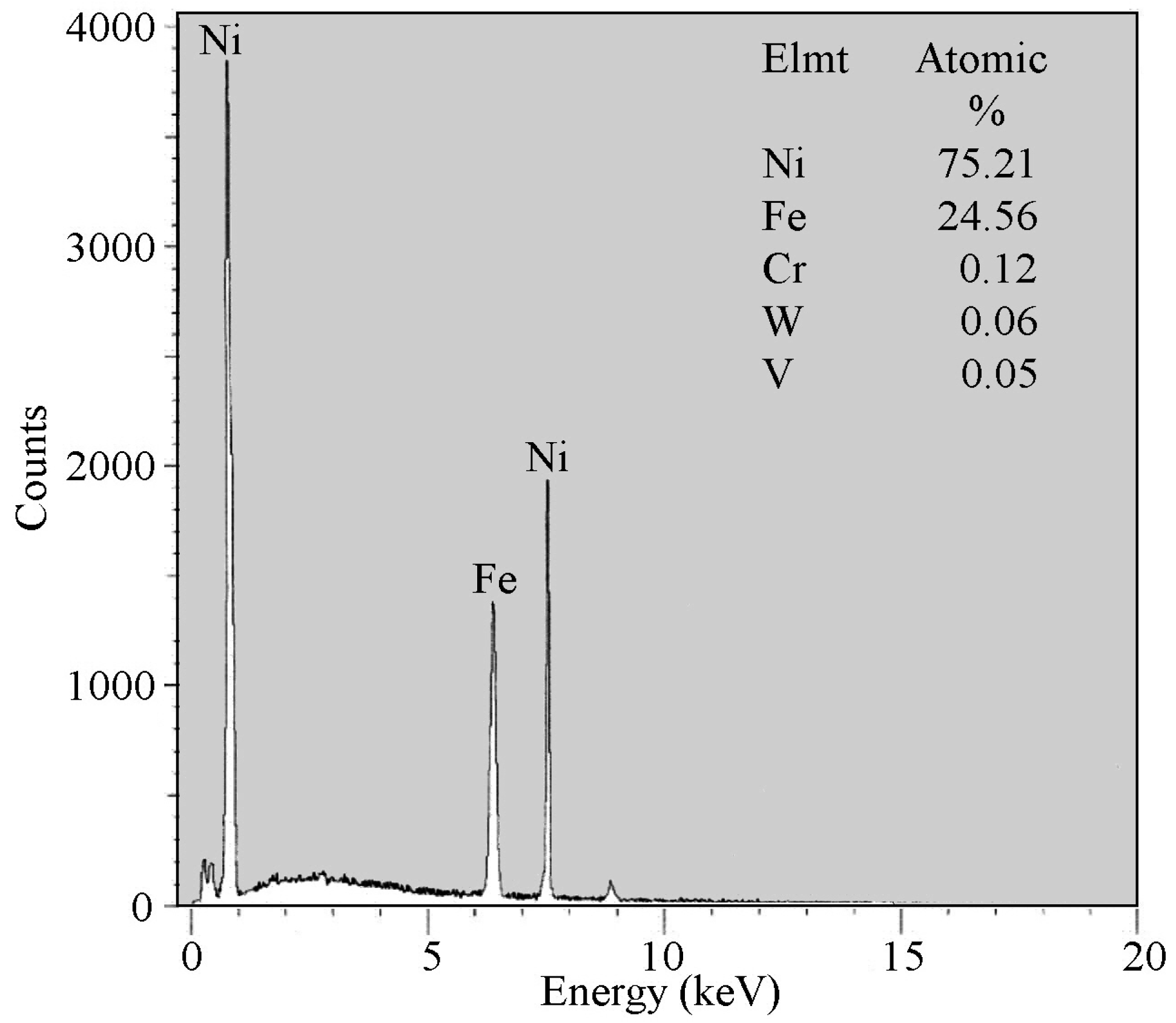
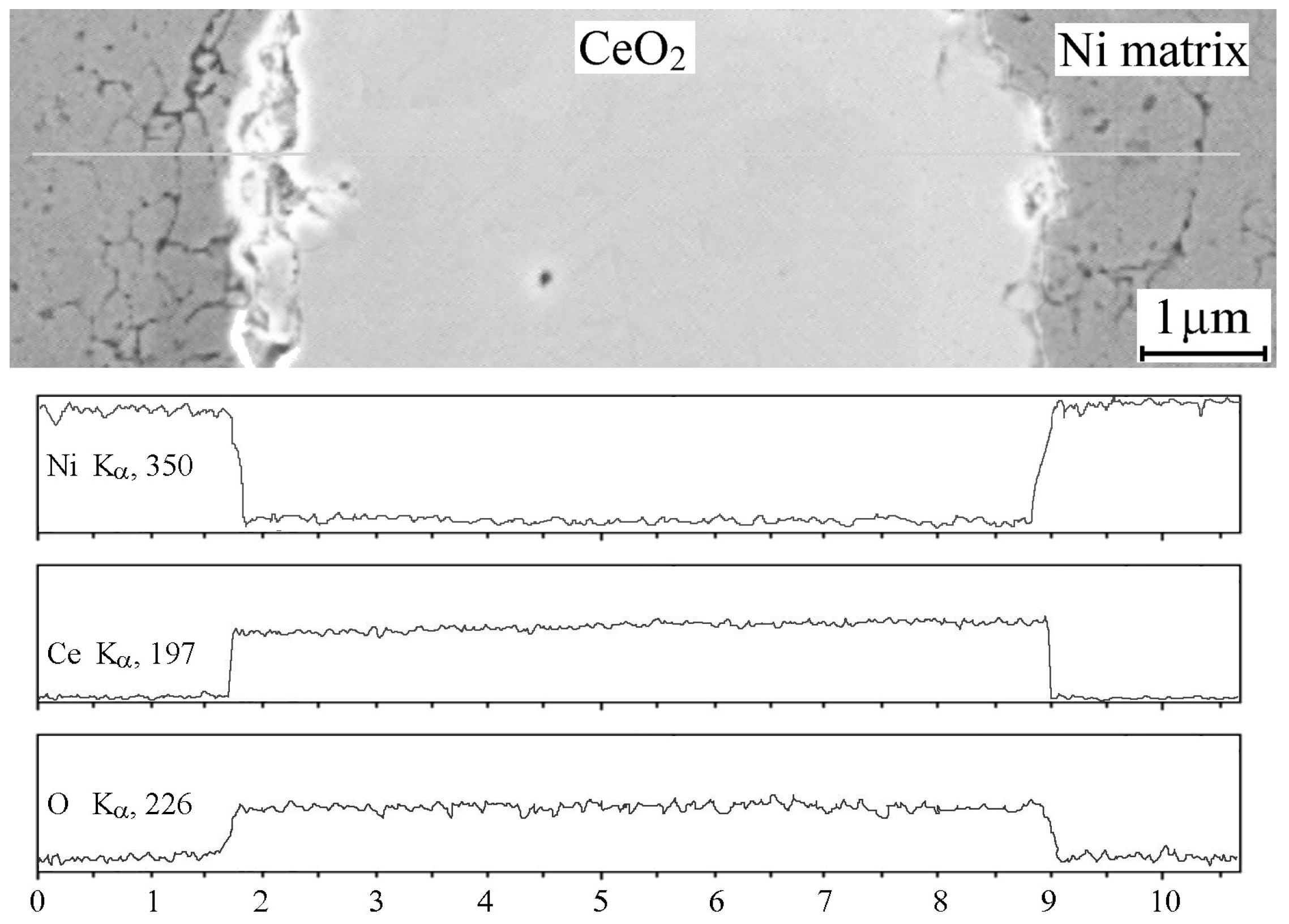
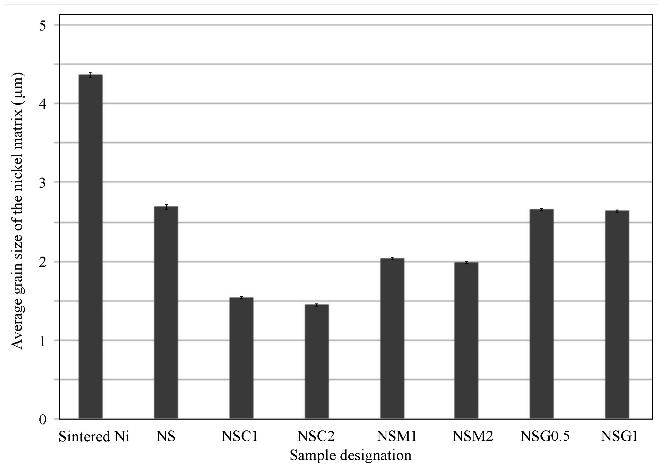
3.1. Microstructural Investigations

Figure 3 illustrates the metallographic micrograph of the composite containing 20 wt.% of T15 HSS particles sintered at 950 °C.
The introduction of a very small content of CeO2, MoS2, or graphite additives into the nickel matrix did not cause significant changes in the microstructure of the composites (Figure 4).
Because the powders were mixed well before being pressed, the T15 HSS and CeO2 particles were evenly spread throughout the nickel matrix. The same was true for composites containing MoS2 or graphite particles. The annealed high-speed steel microstructure has a metal matrix made of ferrite, which includes alloying elements and metal carbides. These metal carbides can be seen in the T15 HSS particle’s microstructure as bright spots against the metal matrix (Figure 4b). The T15 HSS particle is also diffusion-bonded to the nickel matrix. Point scanning was used to measure distribution in this area. The average chemical makeup of the area near the nickel side was found using SEM and EDX analysis: 98.12 wt.% of Ni, 1.37 wt.% of Fe, 0.38 wt.% of Cr, 0.06 wt.% of W, 0.04 wt.% of V, and 0.03 wt.% of Co. This shows that a solid solution based on nickel was created. It was also found that the amounts of Ni, Fe, W, Cr, and V changed a lot in different parts of this area, meaning that the Ni matrix and T15 HSS particles diffused into each other. The diffusion-bonded zone was about 10 mm thick. In some isolated places, the hard secondary phase FeNi3 was identified in the microstructure at the T15 HSS particle–nickel interface with the following average chemical composition: 75.21 wt.% Ni, 24.56 wt.% Fe, and 0.23 wt.% of other elements (Figure 5).
After the addition of the different contents of CeO2, MoS2, and graphite, no new phases were generated, which was confirmed by EDX analysis (Figure 6).
The added particles were uniformly distributed in the nickel matrix with a small amount of aggregation (Figure 4b). Measurements performed for pure nickel sintered at 950 °C showed that the average grain size was 4.37 ± 0.19 μm (Figure 7).
The average size of the nickel matrix grain in the sintered composites containing 20 wt.% of T15 HSS particles was 2.69 ± 0.21 μm. The T15 HSS particles stopped the grains from growing bigger by holding the grain boundary in place, which resulted in a smaller structure of nickel grains. The average grain size of the nickel matrix in the sintered composites containing 20 wt.% of T15 HSS particles and 1 wt.% of CeO2, MoS2, or graphite was 1.55 ± 0.13 μm, 2.04 ± 0.10 μm, and 2.65 ± 0.17 μm, respectively. When the content of CeO2 or MoS2 was 2 wt.%, the average size of the nickel matrix grain in the sintered composites was 1.45 ± 0.12 μm and 1.98 ± 0.11 μm, respectively. When the content of graphite was 0.5 wt.%, the average grain size of the nickel matrix was 2.67 ± 0.19 μm (Figure 8).
It was found that the addition of graphite did not cause any noticeable refinement of the nickel grains. On the other hand, the addition of CeO2 or MoS2 particles caused the nickel grain refinement. This effect was especially visible for CeO2 particles. The refining effect of CeO2 can be explained by two reasons. On the one hand, CeO2 improves the tendency to form more grains, and the number of grains increases, leading to the refinement of grains. On the other hand, due to the rather large atomic radius of rare earth elements, CeO2 is mainly distributed on grain boundaries, inhibiting the growth of grains [21]. Therefore, CeO2 can effectively promote the refinement of the nickel matrix, which contributes to the increased hardness of the composites [15,22].

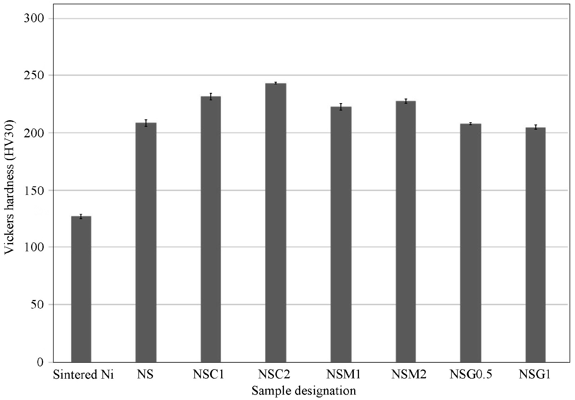
3.2. Density and Hardness Measurements

After sintering, composites with a relative density higher than 94.7% were obtained to inhibit the formation of excessive voids, which was detrimental to their tribological properties (Table 2).
When 20% of T15 HSS particles were added to the nickel matrix, the resulting composite material had a theoretical density of 8.74 g/cm3. The T15 HSS particles had a theoretical density of 8.19 g/cm3, while the nickel matrix had a theoretical density of 8.9 g/cm3. The theoretical densities of the composites containing 20% of T15 HSS particles and 1 or 2 wt.% of CeO2 (density 7.215 g/cm3) are 8.722 and 8.703 g/cm3, respectively. Theoretical densities of composites containing 20% T15 HSS particles and 1 or 2 wt.% of MoS2 (density 5.06 g/cm3) are 8.677 and 8.615 g/cm3, respectively. Theoretical densities of composites containing 20% of T15 HSS particles and 0.5 or 1 wt.% of graphite (density 2.26 g/cm3) are 8.616 and 8.496 g/cm3, respectively. The highest relative density after sintering was obtained for composites containing graphite (Table 2). This was due to the fact that it acted as a solid lubricant, facilitating the sliding of particles over each other during the pressing process. Table 2 and Figure 9 show the hardness of sintered materials with different contents of used particles.
There are many factors affecting the hardness of materials, including composition and structure. It was proven previously [17] that the mismatch of thermal expansion coefficients, grain refinement, and load transfer strengthening were the main strengthening mechanisms that were identified for the Ni–T15 HSS composites. The reasons for the improvement in the Vickers hardness of the composites were as follows: (a) the T15 HSS particles with high hardness were dispersed in the nickel matrix; (b) the addition of T15 HSS and CeO2 or MoS2 particles led to grain refinement. For example, the hardness of the NSC2 (Ni-20%T15 HSS-2%CeO2) is about 16% higher than that of the Ni–T15 HSS composite. CeO2 acts synergistically with T15 HSS via dual phase strengthening: grain boundary pinning and solid particle reinforcement. A similar effect of significant increase in hardness after the addition of CeO2 to nickel was described earlier by Qu et al. [23]. The addition of MoS2 slightly increased the hardness of the composites, but to a lesser extent than CeO2. The addition of graphite did not increase the hardness of the composites, and in fact, at a content of 1%, there was a slight decrease in hardness compared to the other composites. The relatively soft graphite particles acted as pores and were consequently counter-effective in this respect.

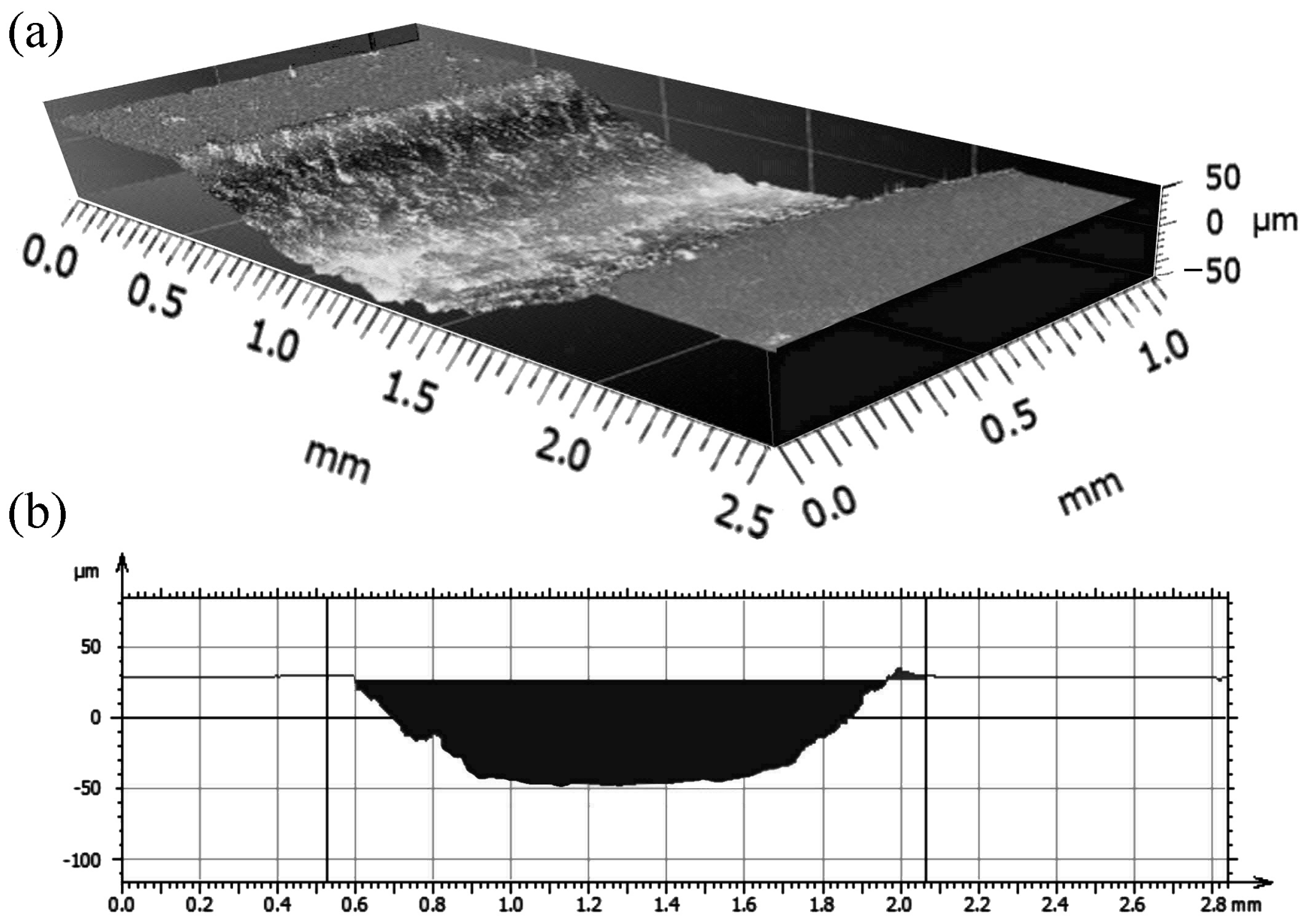
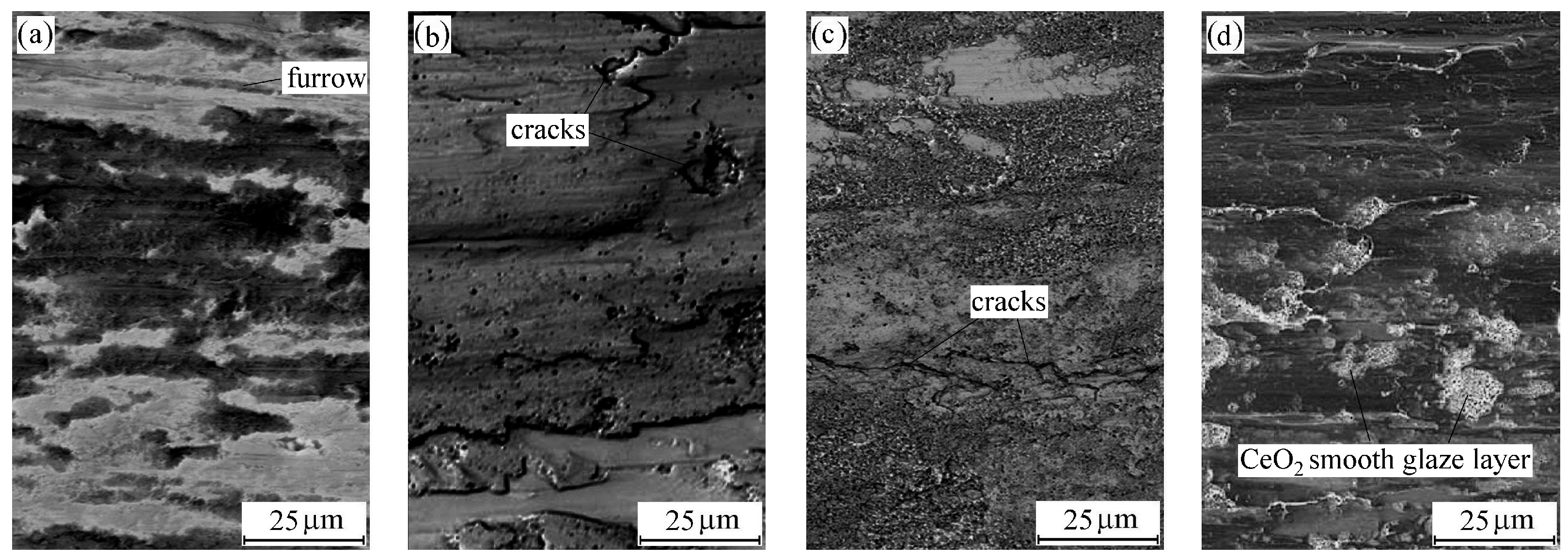
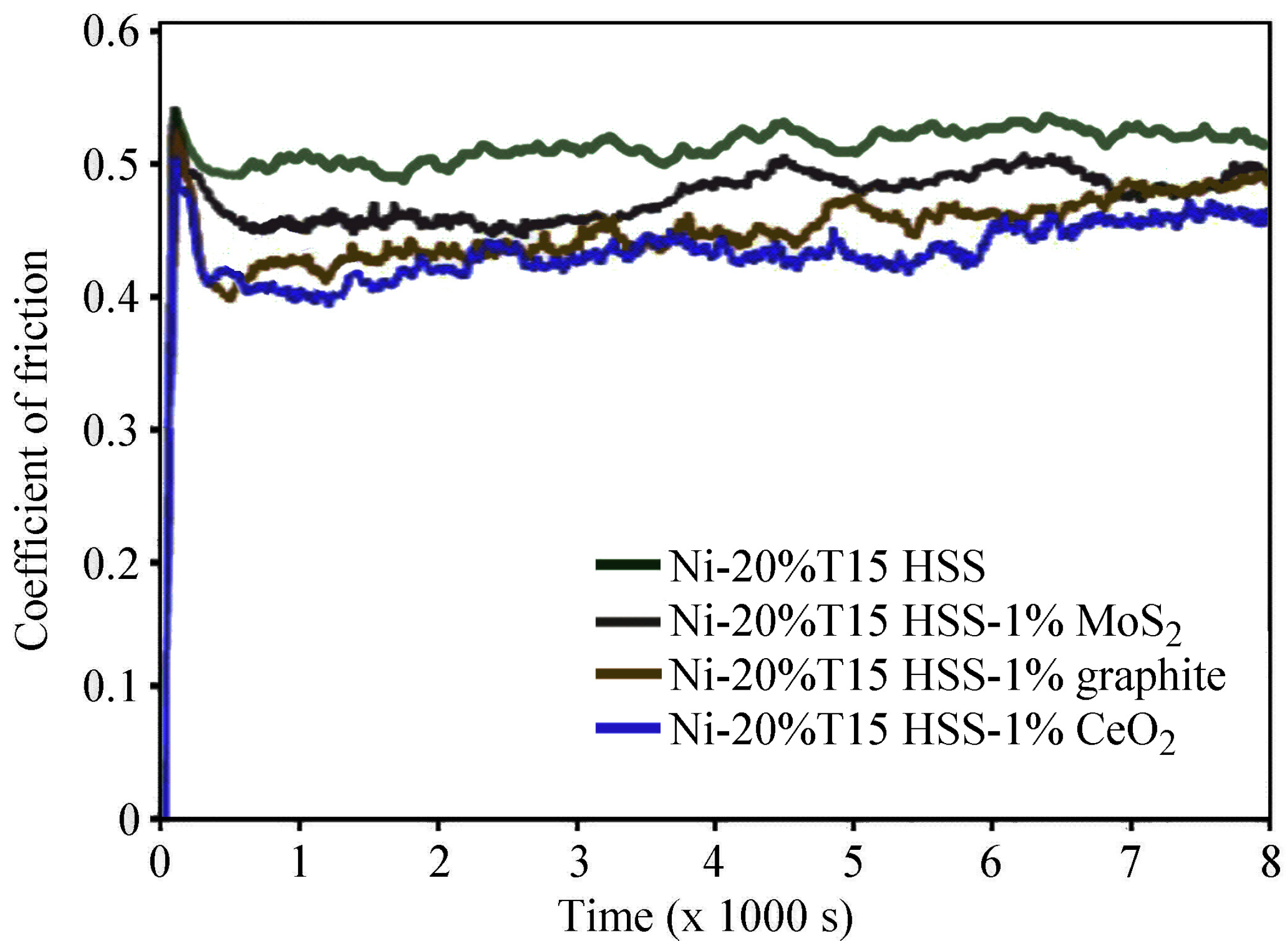
3.3. Tribological Behavior of Ni-T15 HSS Composites

To see how much weight was lost during the abrasion resistance tests, the samples were weighed before and after. The results were compared to a sample made of sintered nickel. Table 3 shows the weight loss, wear volume, and wear rate for all the materials tested.
The 3D profilometer exemplary image, presented in Figure 10, illustrates the changes in the surface morphology of the NSC2 (Ni-20%T15 HSS-2%CeO2) composite after undergoing a tribological test under a constant load of 5 N.
All produced composites were characterized by significantly higher abrasion resistance compared to sintered nickel (Table 3). The wear rate of Ni–T15 HSS composites was gradually reduced as the content of CeO2, MoS2, or graphite particles rose from 0 wt.% to 2 wt.%. In terms of the amount of weight loss and wear rates, all produced composites can be arranged in the following order: Ni–T15 HSS–graphite < Ni–T15 HSS–MoS2 < Ni–T15 HSS–CeO2. The lowest wear rate was achieved for composites containing 2% of CeO2, and it was more than 4 times lower than that of sintered nickel and 1.5 times lower than that of the Ni–T15 HSS composite containing only high-speed steel particles. Li et al. [15] stated that the addition of CeO2 facilitates the formation of a smooth glaze layer during the friction process and reduces the frictional wear of the material. Figure 11 shows the micrographs of the sliding surfaces of the sintered composites.
Sliding wear tracks extending from left to right can be clearly observed on the slip surfaces. These furrows have been created by the plowing action of the relatively hard tool steel onto the composite’s surfaces. Also, elongated grains along the rolling direction can be clearly seen. The shearing deformation manifests itself as severely deformed grains in the direction of the sliding. This phenomenon is typically observed on sliding surfaces of most ductile metals in the direction of the sliding motion. The addition of graphite or MoS2 caused the wear rate to be lower than that of the Ni–T15 HSS composite, but several microcracks can be seen emanating from the slip surface in Figure 11c,d. It indicates that abrasive wear as well as adhesive wear was generated between the composites and the grinding tool-steel ball. No cracks were observed on the slip surface of the composite containing CeO2. The coefficient of friction data was recorded during the tests. Figure 12 shows the coefficient of friction for Ni–T15 HSS composites with 1% of different additives.
The friction coefficient of the composites decreases with the increase in CeO2, MoS2, or graphite particle content. The lowest friction coefficient is characterized by composites containing CeO2 (Table 3 and Figure 12). The obtained results are consistent with the results of Zhang et al. [21], Hu et al. [24], and Qu et al. [23], who intensively studied the effect of CeO2 on the tribological properties of nickel-based composites. The introduction of CeO2 also optimizes the tribological behavior of Ni–T15 HSS composites. Therefore, the wear mechanism of composites with CeO2 changes into slight abrasive wear, which results from the increased hardness of the composites. Furthermore, the decreased adhesive wear also contributes to the smoother friction process and lower friction coefficient. This is a probable result of the formation of a smooth CeO2 glaze layer during the friction process. The statement about a CeO2 glass layer is speculative, and its existence would need to be verified by surface chemistry or XPS/EDS, which was not performed in the scope of this work. A close correlation was observed between hardness, grain size, friction coefficient, and wear rate. The addition of CeO2 (especially in the amount of 2%) caused the composites to be characterized by the highest hardness, the smallest grain size, the lowest friction coefficient, and the lowest wear rate.

4. Conclusions

In this study, Ni–T15 HSS composites were made using powder metallurgy methods. The effect of CeO2, MoS2, or graphite additives on the tribological properties of the composites was investigated. The main conclusions are as follows:
  • The maximum hardness of 243 HV can be achieved for the Ni-20 wt.%T15 HSS-2% CeO2, which is about 16% higher than that of the Ni–T15 HSS composite.
  • The wear rate of the Ni–T15 HSS composites reduces from 3.4782 × 10⁻⁷ cm3/N∙m to 2.0222 × 10⁻⁷ cm3/N∙m as the content of CeO2 rises from 0 wt.% to 2 wt.%.
  • The wear mechanisms of composites with MoS2 or graphite are abrasive wear and adhesive wear.
  • The introduction of CeO2 enhances the hardness of composites, leading to a change in the wear mechanism of composites to slight abrasive wear.
  • The addition of CeO2 can effectively optimize the tribological properties of Ni–T15 HSS composites.
  • Ni–T15 HSS composites, especially with the addition of CeO2, seem to have significant potential for industrial applications in high-wear environments and are an interesting source of future work on high-temperature performance and fatigue resistance.

Funding

This research received no external funding.

Data Availability Statement

The original contributions presented in this study are included in the article. Further inquiries can be directed at the author.

Conflicts of Interest

The author declares no conflicts of interest.

References

  1. Sharma, D.; Mahant, D.; Upadhyay, G. Manufacturing of metal matrix composites: A state of review. Mater. Today-Proc. 2020, 26, 506–519. [Google Scholar] [CrossRef]
  2. Sankhla, A.; Patel, K. Metal matrix composites fabricated by stir casting process—A review. Adv. Mater. Process. Technol. 2022, 8, 1270–1291. [Google Scholar] [CrossRef]
  3. Qu, X.; Zhang, L.; Wu, M.; Ren, S. Review of metal matrix composites with high thermal conductivity for thermal management applications. Prog. Nat. Sci. 2011, 21, 189–197. [Google Scholar] [CrossRef]
  4. Srivastava, A.; Dixit, A.; Tiwari, S. A review on the intensification of metal matrix composites and its nonconventional machining. Sci. Eng. Compos. Mater. 2018, 25, 213–228. [Google Scholar] [CrossRef]
  5. Konieczny, M. The effect of sintering temperature, sintering time, and reinforcement particle size on properties of Al-Al2O3 composites. Compos. Theory Pract. 2012, 12, 39–43. [Google Scholar]
  6. Kargul, M.; Konieczny, M. Copper matrix composites reinforced with steel particles. AIMS Mater. Sci. 2021, 8, 321–342. [Google Scholar] [CrossRef]
  7. Szewczyk-Nykiel, A. Microstructure and properties of sintered metal matrix composites reinforced with SiC particles. Tech. Trans. 2017, 6, 179–190. [Google Scholar]
  8. Kumar, B.; Ananthaprasad, G.; Krishna, K. A Review on mechanical and tribological behaviors of nickel matrix composites. Indian J. Sci. Technol. 2016, 9, 1–7. [Google Scholar]
  9. Park, B.; Lee, J.; Park, J.; Park, H. Comparative study of Ni-TaC composites via high-energy ball milling activation and spark plasma sintering: Reinforcement, densification, oxidation resistance, and mechanical property. J. Alloys Compd. 2024, 984, 173900. [Google Scholar] [CrossRef]
  10. Tyagi, R.; Xiong, D.; Li, J.; Dai, J. Elevated temperature tribological behavior of Ni based composites containing nano-silver and hBN. Wear 2010, 269, 884–890. [Google Scholar] [CrossRef]
  11. El-Wazery, M.; El-Desouk, A.; Hamed, O.; Fathy, A.; Mansour, N. Electrical and mechanical performance of zirconia-nickel functionally graded materials. Int. J. Eng. Trans. A Basics 2013, 26, 375–382. [Google Scholar] [CrossRef]
  12. Karayannis, V.; Moutsatsou, A. Synthesis and characterization of nickel-alumina composites from recycled nickel powder. Adv. Mater. Sci. Eng. 2012, 395612. [Google Scholar] [CrossRef]
  13. Yamada, T. Nickel-base composite materials and their bonding. Weld. Int. 1990, 4, 593–599. [Google Scholar] [CrossRef]
  14. Li, F.; Cheng, J.; Zhu, S.; Hao, J.; Yang, J.; Liu, W. Microstructure and mechanical properties of Ni-based high-temperature solid-lubricating composites. Mater. Sci. Eng. A-Struct. 2017, 682, 475–481. [Google Scholar] [CrossRef]
  15. Li, J.; Xiong, D.; Huang, Z.; Kong, J.; Dai, J. Effect of Ag and CeO2 on friction and wear performance of Ni-base composite at high temperature. Wear 2009, 267, 576–584. [Google Scholar] [CrossRef]
  16. Xue, M. Tribological behaviour of Ni-Cr based composite at high temperature. Trans. Non-ferrous Met. Soc. China 2007, 17, 570–574. [Google Scholar]
  17. Konieczny, M. Properties and strengthening mechanisms of nickel matrix composites reinforced with high-speed steel particles. Compos. Theory Pract. 2024, 12, 116–122. [Google Scholar] [CrossRef]
  18. EN ISO 2738:2001; Sintered Metal Materials, Excluding Hardmetals—Permeable Sintered Metal Materials—Determination of Density, Oil Content and Open Porosity. International Organization for Standardization: Geneva, Switzerland, 2001.
  19. ASTM G 99; Standard Test Method for Wear Testing with a Pin-on-Disk Apparatus. ASTM International: West Conshohocken, PA, USA, 2003.
  20. EN ISO 6507-1:2023; Metallic Materials—Vickers Hardness Test. International Organization for Standardization: Geneva, Switzerland, 2023.
  21. Zhang, Z.; Wang, Z.; Liang, P. Effects of CeO2 on friction and wear characteristics of Fe-Ni-Cr alloy castings. Tribol. Int. 2006, 39, 971–978. [Google Scholar] [CrossRef]
  22. Zhu, Y.; Qi, Q.; Wang, L.; Zhao, Y.; Yang, X.; Zhang, X. The influence of CeO2 on the oxidation resistance of TaC/Ni composites. J. Alloys Compd. 2024, 177147. [Google Scholar] [CrossRef]
  23. Qu, N.; Hu, X.; Qian, W.; Zhu, Z. Enhancement of microhardness and wear resistance of Ni-CeO2 nanocomposite coatings. Surf. Eng. 2014, 30, 159–164. [Google Scholar] [CrossRef]
  24. Hu, T.; Shi, Z.; Shao, W.; Xing, X.; Zhou, Y.; Yang, Q. Effect of CeO2 on density and wear resistance of Ni-Cr-WC coatings by theoretical calculations and experimental investigation. Surf. Coat. Technol. 2019, 377, 124850. [Google Scholar] [CrossRef]
Figure 1. SEM micrographs of powders used in the experiments: (a) nickel; (b) T15 HSS, Adapted from [17]; (c) CeO2; and (d) MoS2.
Metals 15 00772 g001aMetals 15 00772 g001b
Figure 2. A schematic diagram of the experimental procedures.
Metals 15 00772 g002
Figure 3. OM micrograph of the composite containing 20 wt.% of T15 HSS particles.
Metals 15 00772 g003
Figure 4. Micrographs of the composite containing 20 wt.% of T15 HSS and 2 wt.% of CeO2 particles: (a) OM micrograph, (b) SEM micrograph.
Metals 15 00772 g004
Figure 5. The energy spectrum of emitted X-rays for the FeNi3 intermetallic phase.
Metals 15 00772 g005
Figure 6. SEM micrograph of the cross–sectional view of a Ni/CeO2 interconnection and corresponding EPMA line-scans for Ni, Ce, and O.
Metals 15 00772 g006
Figure 7. Grain size measurement results for pure sintered nickel.
Metals 15 00772 g007
Figure 8. Average grain size of the nickel matrix in the sintered nickel and composites containing T15 HSS particles and CeO2, MoS2, or graphite.
Metals 15 00772 g008
Figure 9. Hardness measurement results for investigated materials.
Metals 15 00772 g009
Figure 10. Surface texture topography of the NSC2 composite after tribological test under dry friction: (a) isometric image, (b) wear cross-section profile.
Metals 15 00772 g010
Figure 11. Scanning electron micrographs of the sliding surfaces of sintered composites: (a) Ni–T15 HSS, (b) Ni–T15 HSS–1% graphite, (c) Ni–T15 HSS–2% MoS2, and (d) Ni–T15 HSS–2% CeO2.
Metals 15 00772 g011
Figure 12. Friction coefficient as a function of test time for Ni–T15 HSS composites containing 1% CeO2, MoS2, or graphite particles.
Metals 15 00772 g012
Table 1. The composition of the composites.
Sample
Designation
Nickel
wt.%
T15 HSS
wt.%
CeO2
wt.%
MoS2
wt.%
Graphite
wt.%
NS8020000
NSC17920100
NSC27820200
NSM17920010
NSM27820020
NSG0.579.520000.5
NSG17920001
Table 2. Density, relative density, and Vickers hardness of sintered nickel and composites.
SampleMeasured Density (g/cm3)Relative Density (%)Vickers Hardness (HV30)
Sintered Ni8.655 ± 0.0397.25127 ± 2
NS8.326 ± 0.0295.27209 ± 3
NSC18.295 ± 0.0395.11232 ± 3
NSC28.248 ± 0.0194.78243 ± 1
NSM18.261 ± 0.0295.21223 ± 3
NSM28.178 ± 0.0394.93228 ± 2
NSG0.58.405 ± 0.0297.55208 ± 1
NSG18.335 ± 0.0198.11205 ± 2
Table 3. Weight loss, wear volume, wear rate, and coefficient of friction of investigated materials.
SampleWeight Loss
(g)
Wear Volume
(×10−3 cm3)
Wear Rate
(cm3/N∙m)
Coefficient of Friction
Sintered Ni0.03954.43828.8764 × 10−70.618
NS0.01521.73913.4782 × 10−70.523
NSC10.01031.18092.3618 × 10−70.427
NSC20.00881.01112.0222 × 10−70.418
NSM10.01461.68263.3652 × 10−70.492
NSM20.01281.48572.9714 × 10−70.461
NSG0.50.01511.73253.4650 × 10−70.497
NSG10.01461.71843.4368 × 10−70.451
Disclaimer/Publisher’s Note: The statements, opinions and data contained in all publications are solely those of the individual author(s) and contributor(s) and not of MDPI and/or the editor(s). MDPI and/or the editor(s) disclaim responsibility for any injury to people or property resulting from any ideas, methods, instructions or products referred to in the content.

