
Effect of Laser Power on Microstructure and Tribological Performance of Ni60/WC Bionic Unit Fabricated via Laser Cladding


Abstract
1. Introduction
2. Materials and Methods
2.1. Material and Laser Cladding
2.2. Surface Roughness Measurement
2.3. Microstructure Observation and XRD Measurement
2.4. Hardness Measurement
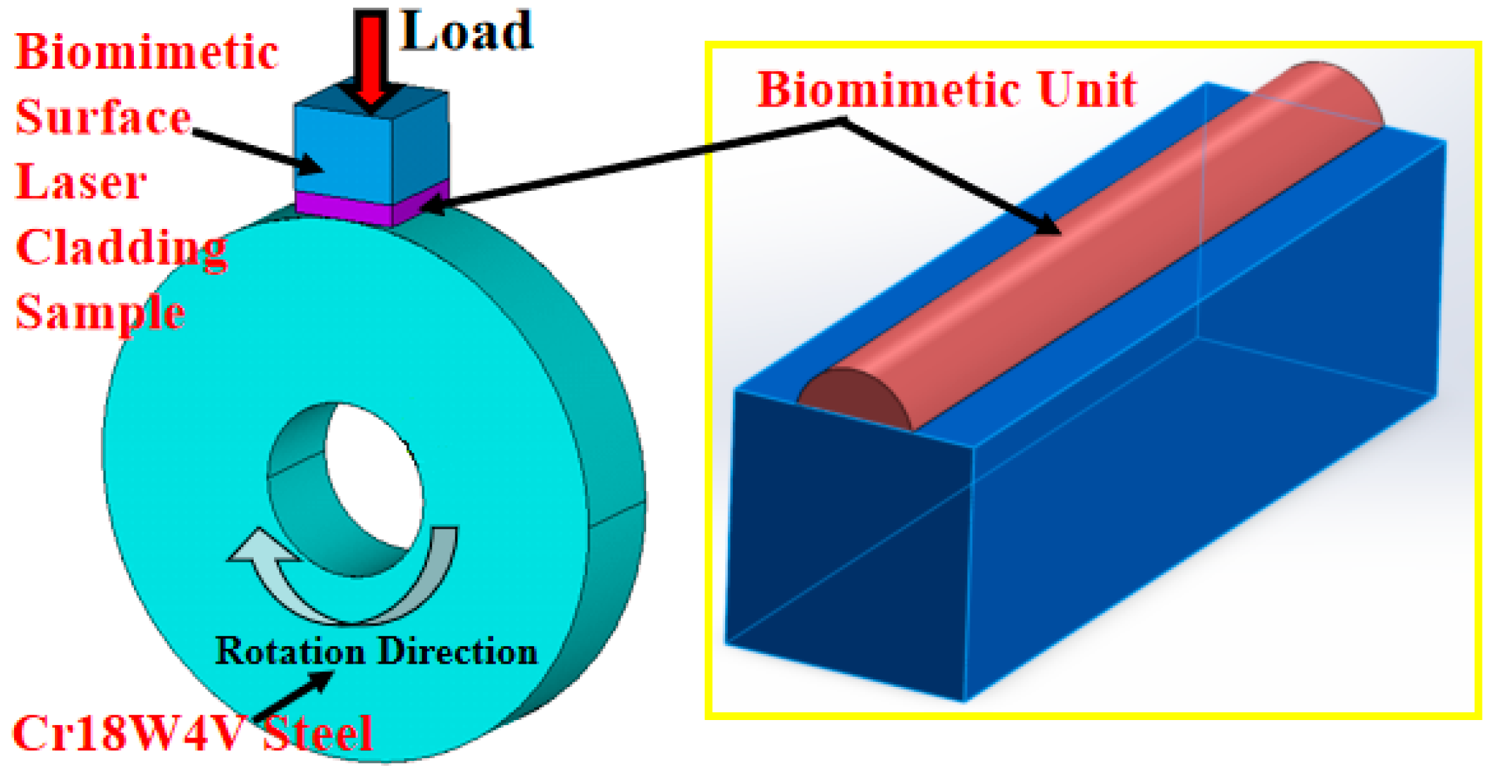
2.5. Wear Tests
3. Results and Discussion
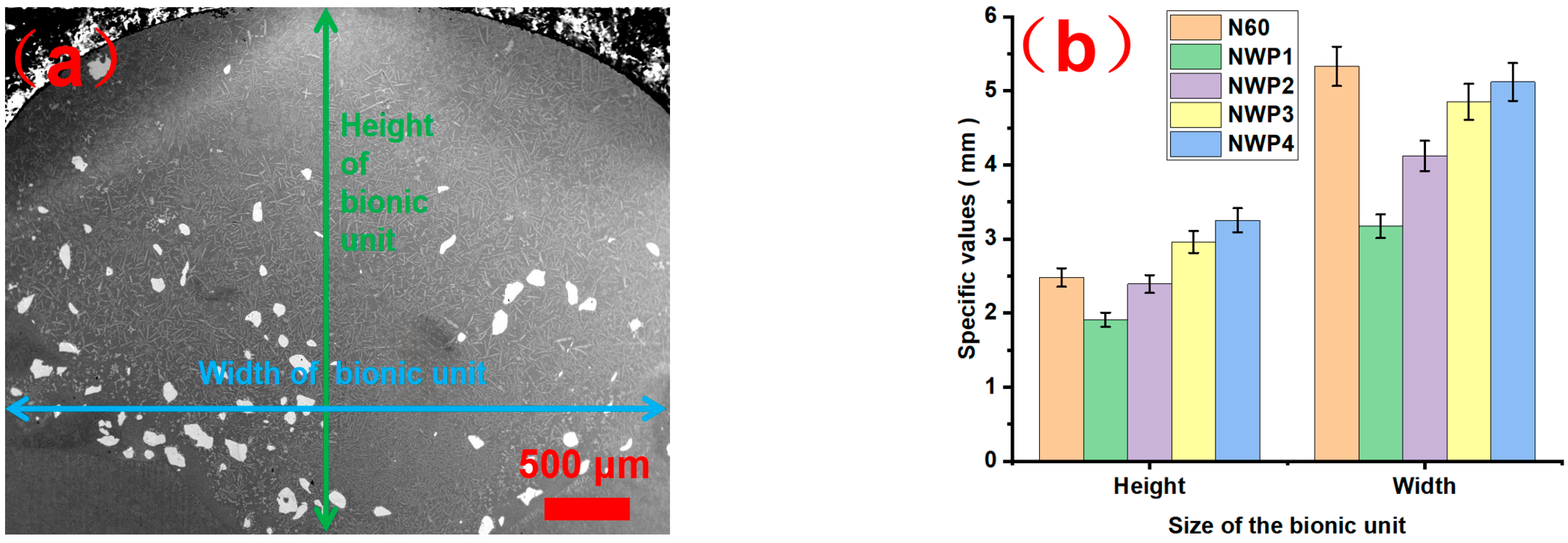
3.1. Dimensions
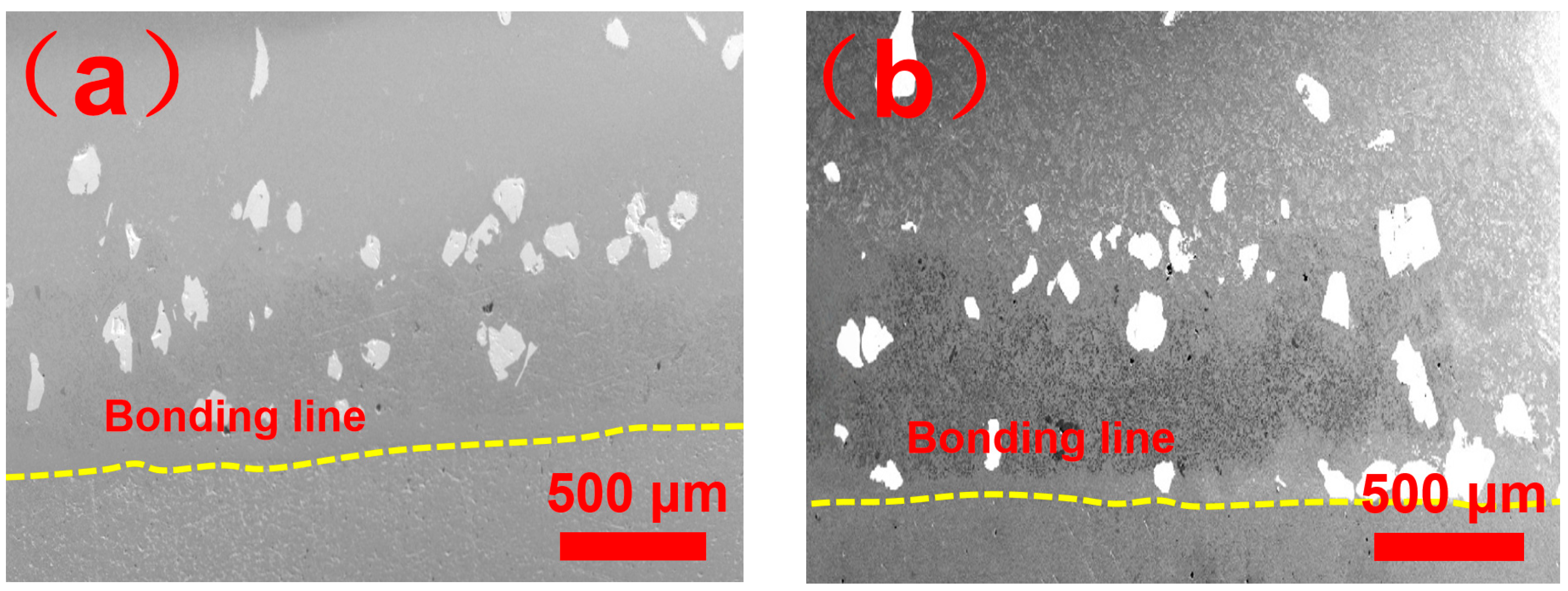
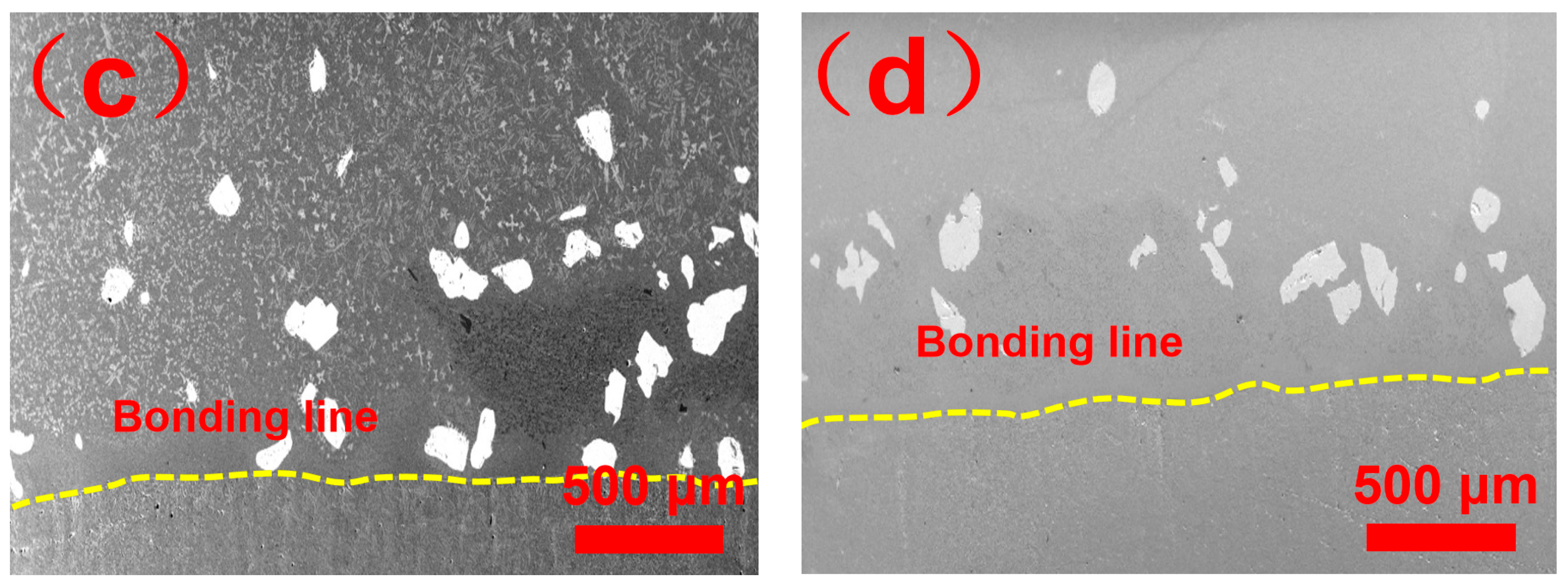
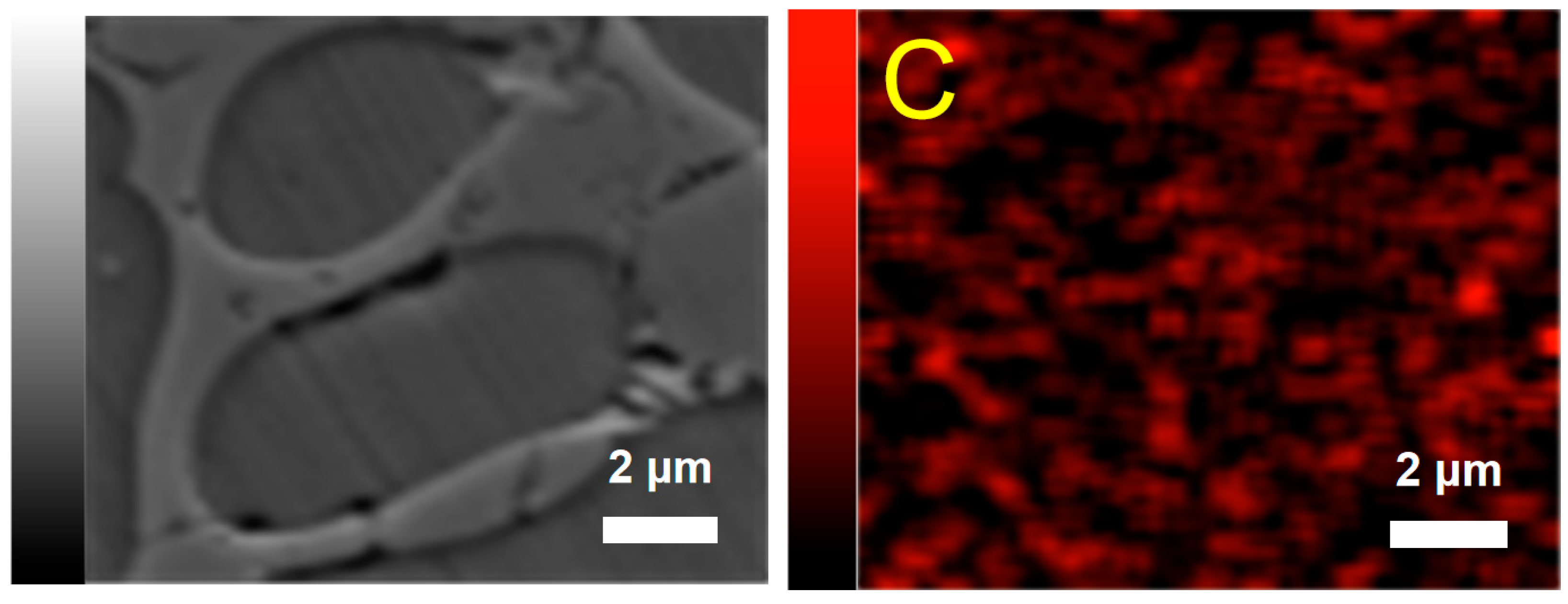
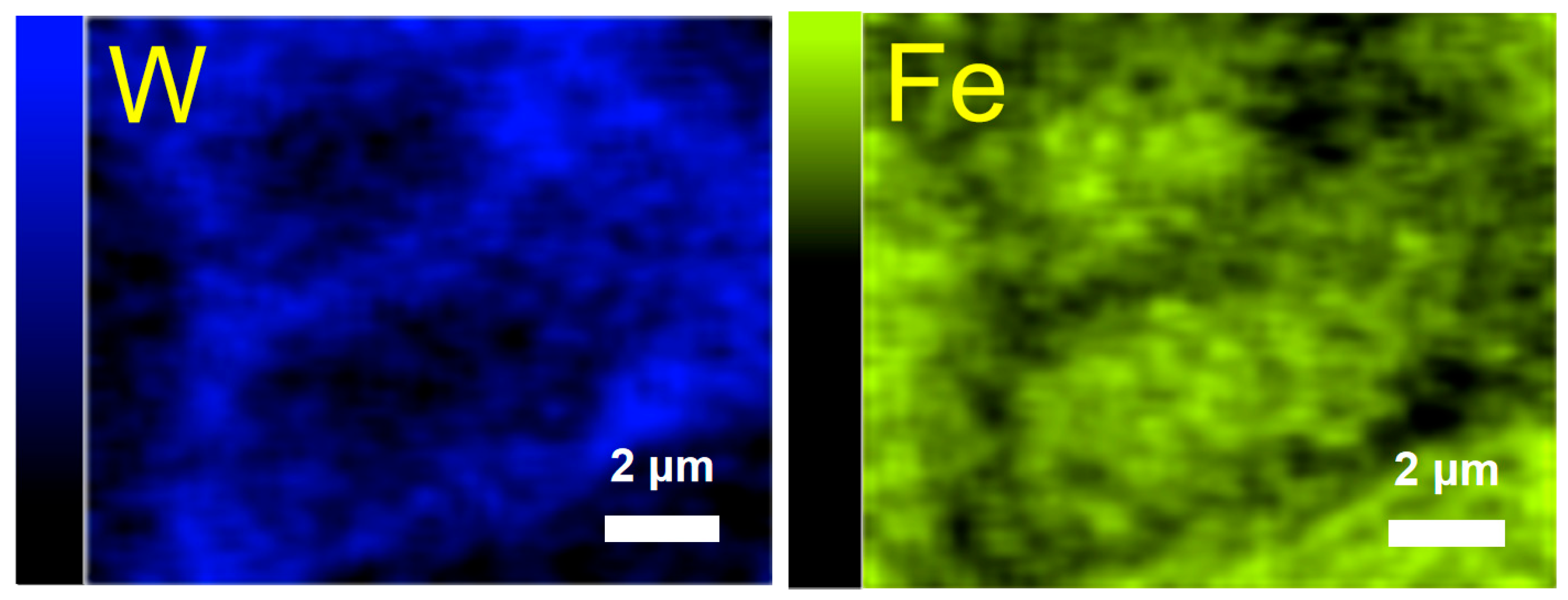
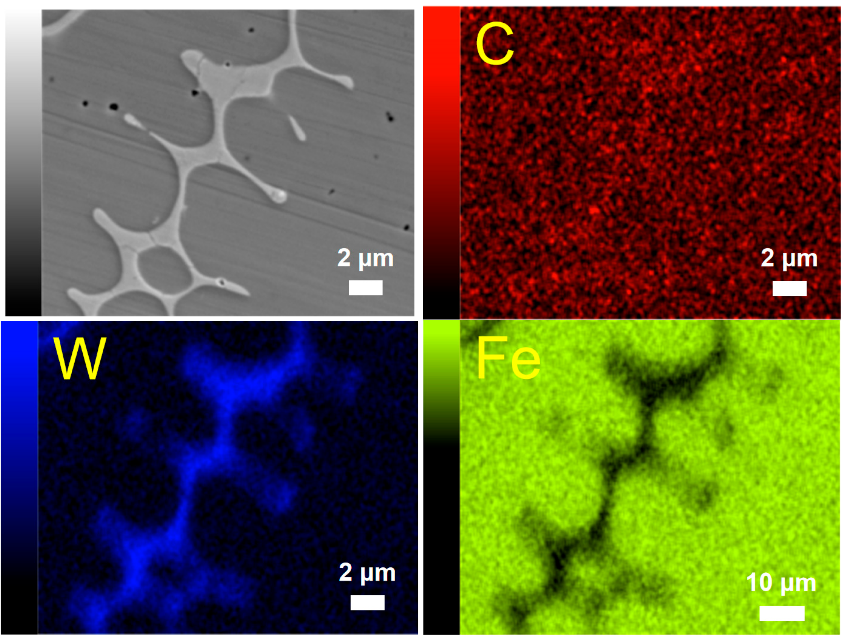
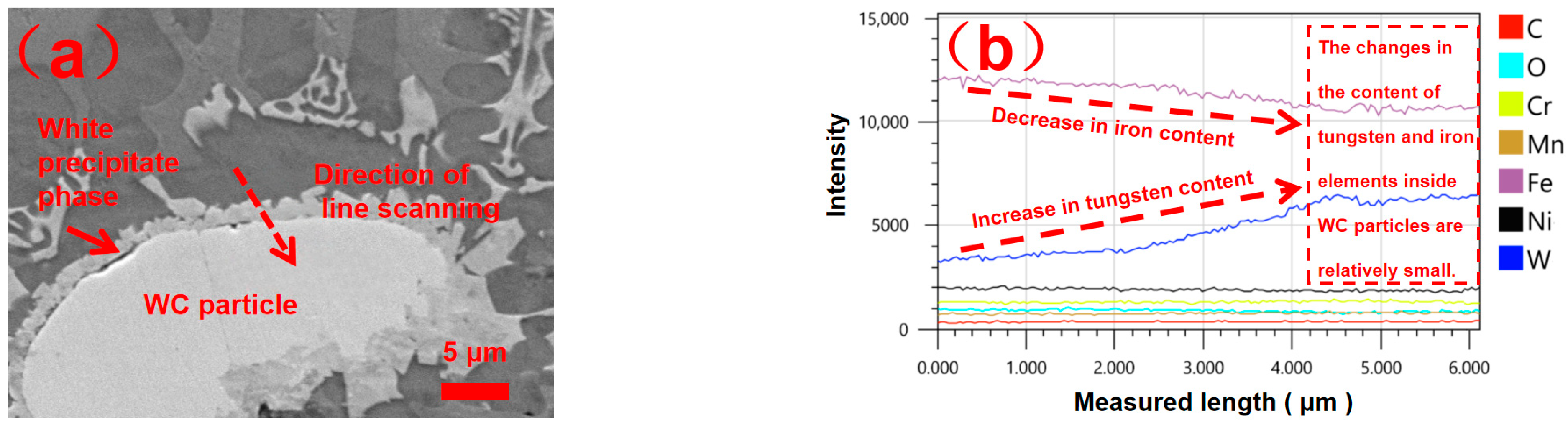
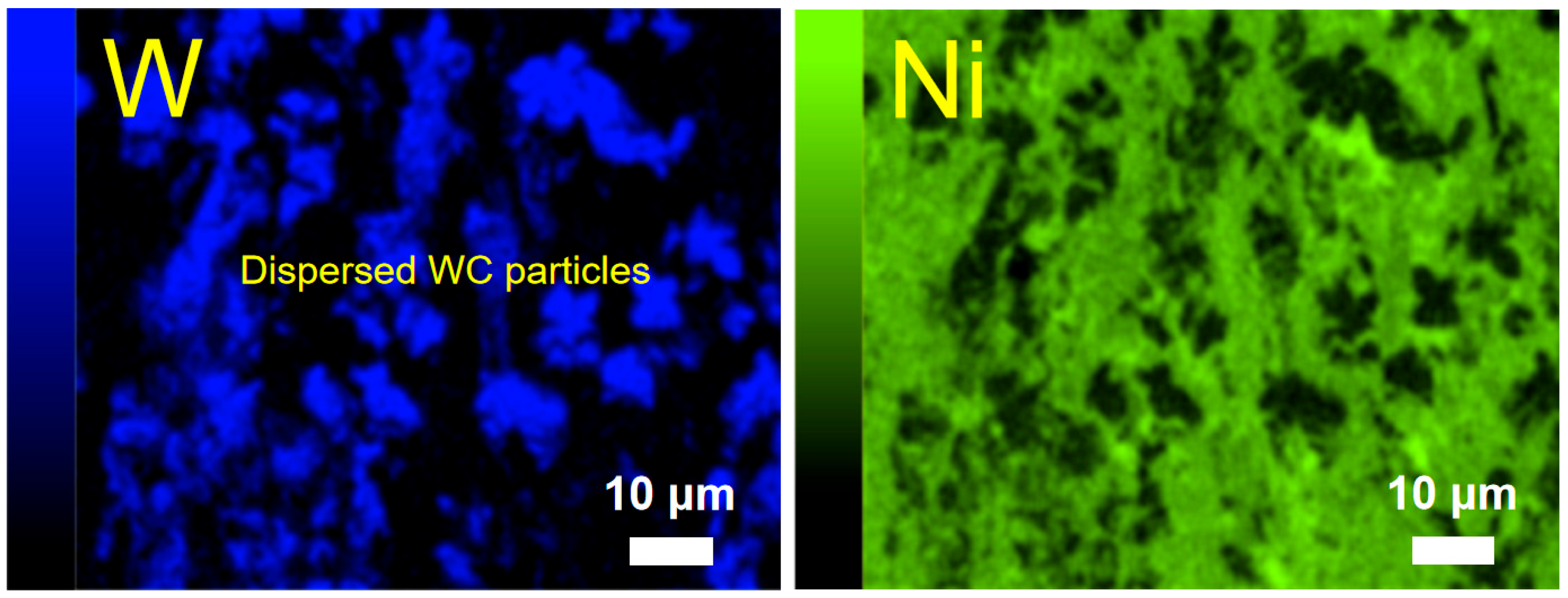
3.2. Microstructure
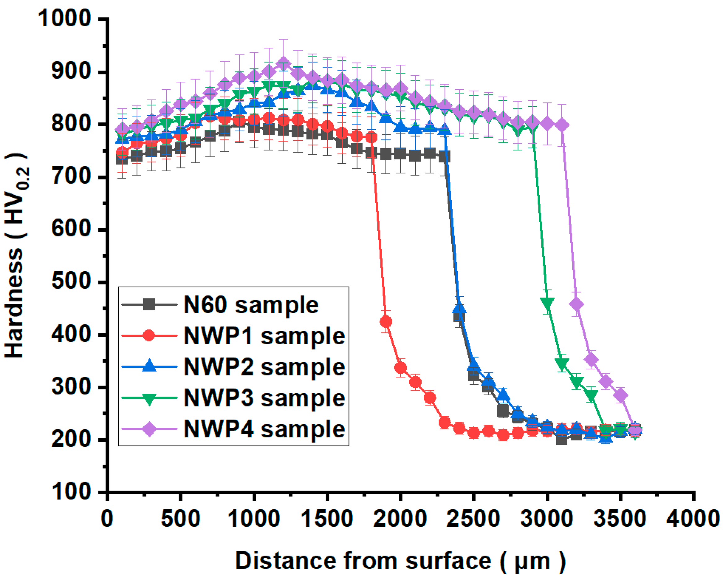
3.3. Hardness
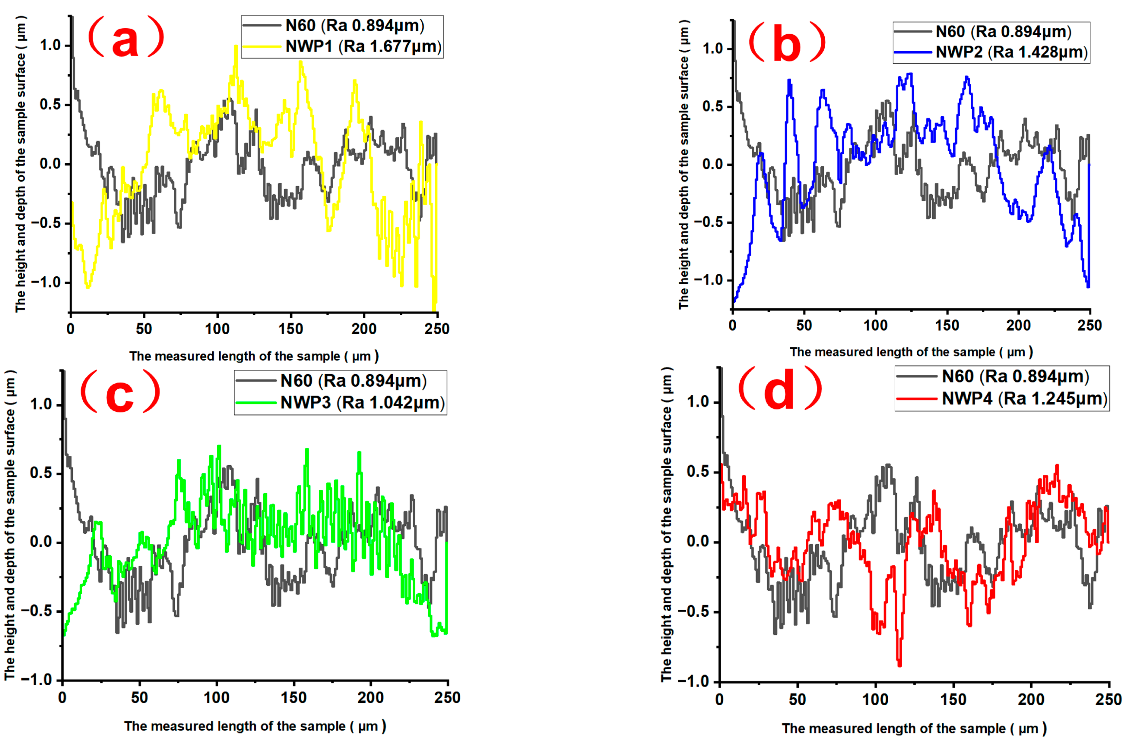
3.4. Surface Roughness
3.5. Wear Test Results
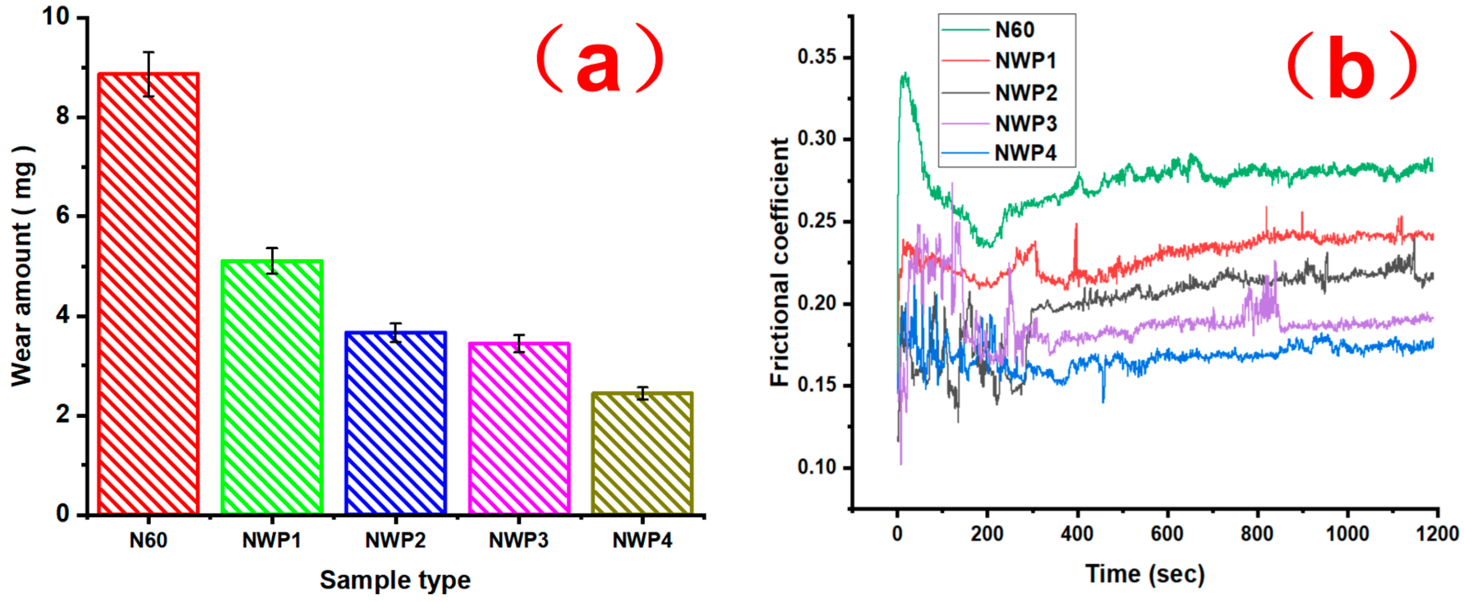
3.5.1. Tribological Performance
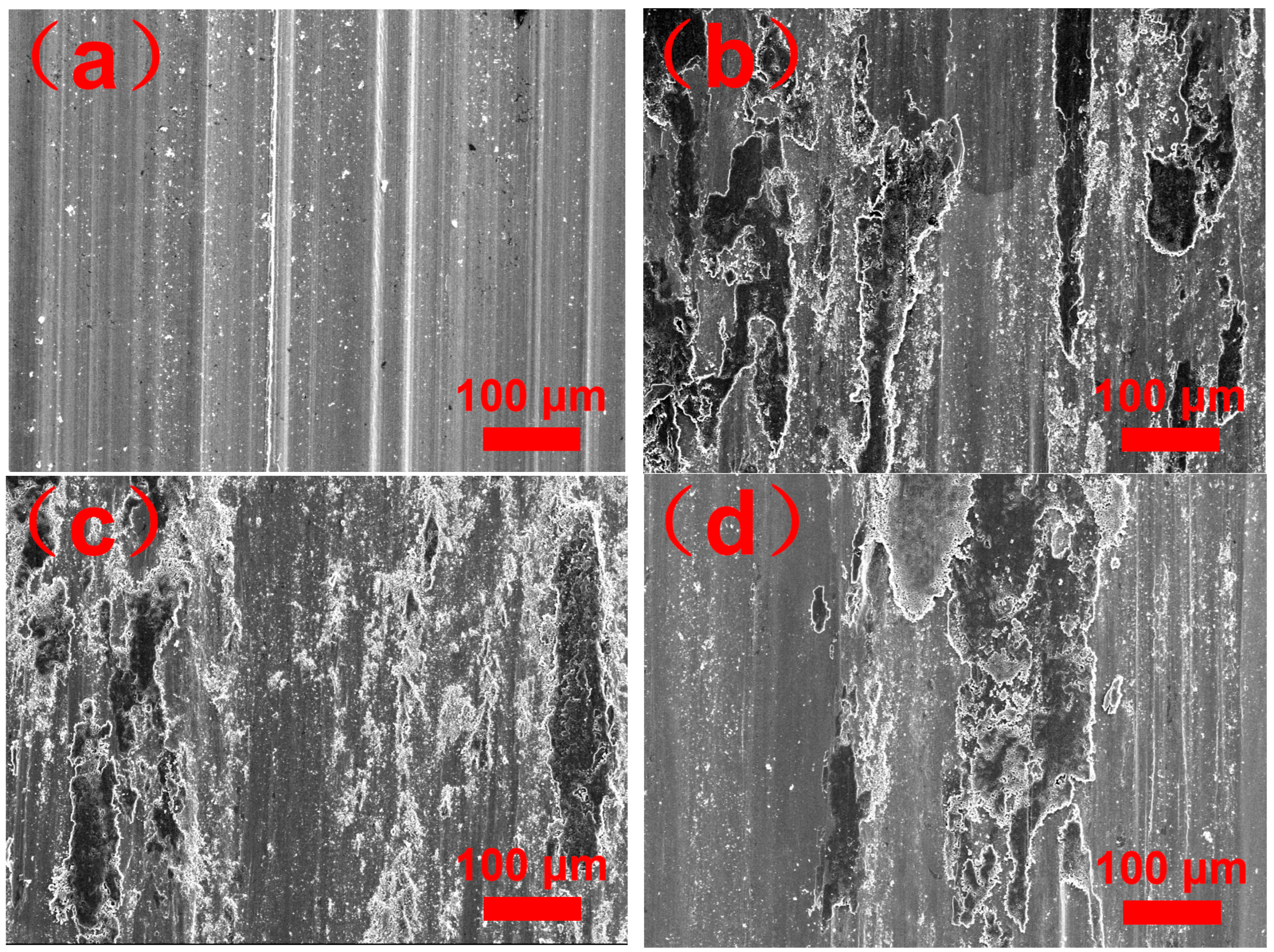
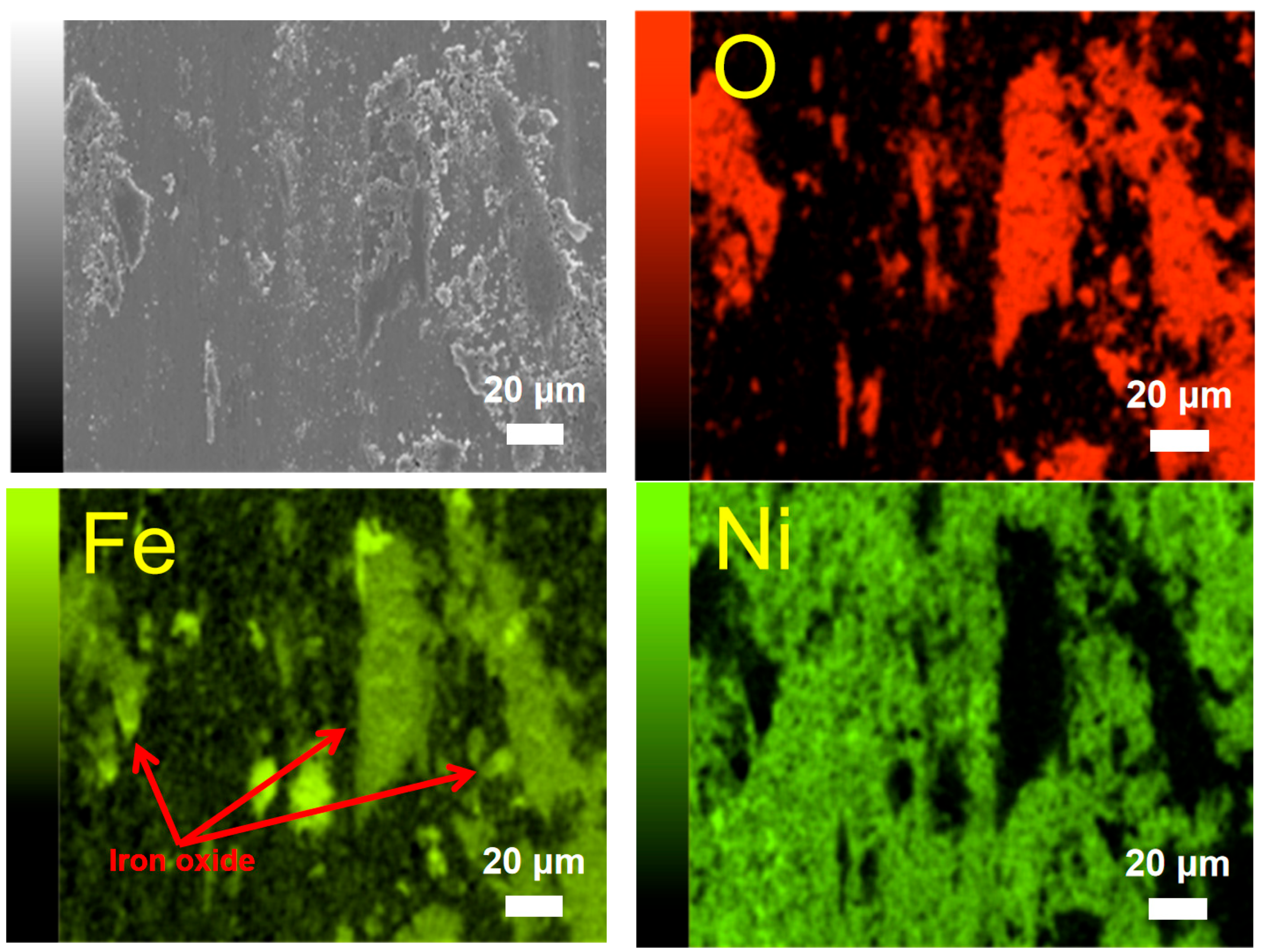
3.5.2. Wear Morphology
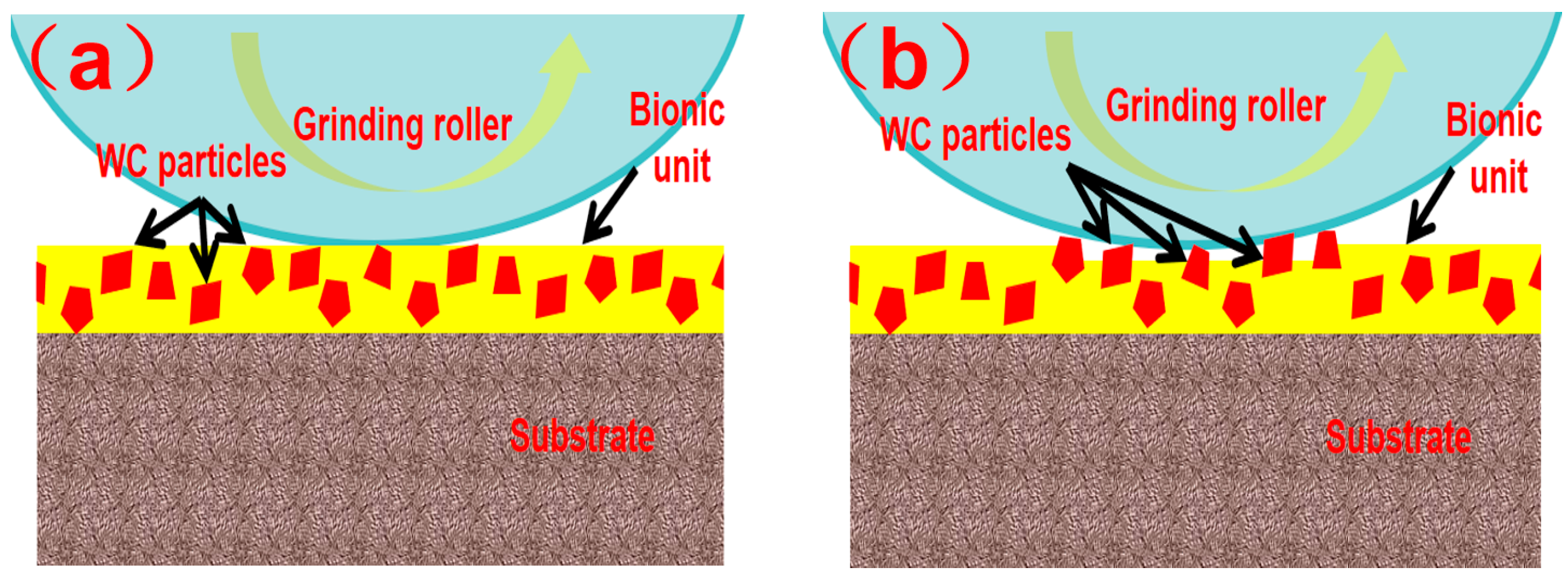
3.5.3. The Wear Resistance Mechanism
- (1)
- Dispersion Strengthening
- (2)
- Microstructure
- (3)
- Hardness
- (4)
- Surface roughness
4. Conclusions
Author Contributions
Funding
Data Availability Statement
Conflicts of Interest
References
- Reddy, G.; Madhu, S.; Prasad, C.D.; Kumar, B.K.P.; Sollapur, S.B. Investigation of hot corrosion behavior of plasma sprayed cermet composite coatings on titanium and special steel alloys. Surf. Coat. Technol. 2025, 499, 131883. [Google Scholar] [CrossRef]
- Alam, M.S.; Das, A.K. Surface morphological studies on hot corrosion behaviour of pre-oxidized plasma sprayed WC-CoCr coating on AISI316L steel in Na2SO4/NaCl molten salt environment. Phys. Scr. 2025, 100, 15943. [Google Scholar] [CrossRef]
- Mallick, R.; Kumar, R.; Panda, A.; Sahoo, A.K. A Novel Application of MgO Nano-cutting Fluid in Hardened AISI D2 Steel Machining Using a Chemical Vapor Deposition-Coated Carbide Tool. J. Mater. Eng. Perform. 2025, 34, 330–355. [Google Scholar] [CrossRef]
- Meysami, A.; Najafabadi, R.A.; Yosefnejad, T. Enhancing Wear Behavior and Hardness of D5 Cold Work Tool Steel through TiCrN Multilayer Nanocoating via Physical Vapor Deposition. Surf. Eng. Appl. Electrochem. 2024, 60, 58–68. [Google Scholar] [CrossRef]
- Locks, E.; He, Q.X.; Depaiva, J.M.; Guimaraes, M. Investigating the Impact of Physical Vapour Deposition (PVD)-Coated Cutting Tools on Stress Corrosion Cracking Susceptibility in Turning Super Duplex Stainless Steel. Coatings 2024, 14, 290. [Google Scholar] [CrossRef]
- Aktas, C.G.; Fountas, K.; Atapek, S.H.; Polat, S. Investigation of the Nitriding Effect on the Adhesion and Wear Behavior of CrN-, AlTiN-, and CrN/AlTiN-Coated X45CrMoV5-3-1 Tool Steel Formed Via Cathodic Arc Physical Vapor Deposition. Lubricants 2024, 12, 170. [Google Scholar] [CrossRef]
- Rafiei, J.; Ghasemi, A.R. Experimental Study of Stainless-Steel Nanoparticles Coating on Carbon Steel Using the Laser Cladding Approach. Mech. Compos. Mater. 2025, 60, 1183–1194. [Google Scholar] [CrossRef]
- Chen, X.; Wang, J.L.; Ke, D.W.; Wen, K. Numerical simulation and structure properties of laser clad 316 L stainless steel coating. Appl. Phys. A Mater. Sci. Process. 2025, 131, 111. [Google Scholar] [CrossRef]
- Zu, H.Y.; Liu, Y.P.; Chen, S.H.; Jin, X.; Ye, W.D. Forming Process Prediction Model and Application of Laser Cladding for Remanufactured Screw Pump Rotors. Materials 2025, 18, 1673. [Google Scholar] [CrossRef]
- Hu, K.X.; Huang, Q.Y.; Wang, L.; Zhou, Y.; Li, W.D. Optimization of multi-track, multi-layer laser cladding process parameters using Gaussian process regression and improved multi-objective particle swarm optimization. Int. J. Adv. Manuf. Technol. 2025, 137, 3503–3523. [Google Scholar] [CrossRef]
- Lu, D.; Cui, X.C.; Zhang, J.W. Microstructure and properties of high entropy alloy coating obtained by laser cladding. Sci. Rep. 2025, 15, 7357. [Google Scholar] [CrossRef]
- Liu, Z.B.; Han, C.H.; Cao, X.J.; Guo, J.; Li, H.X.; Lin, Y.J.; Yang, J. Microstructure and wear behavior of AISI 316L austenitic stainless steel coating fabricated by laser cladding and plasma nitriding. Mater. Lett. 2025, 383, 137951. [Google Scholar] [CrossRef]
- Wang, J.Y.; Cui, X.F.; Zhao, Y.; Zhang, Y.; Jin, G.; Feng, C.C. Microstructure and corrosion performance of Fe-based composite layer doped modification with Ti6Al4V fabricated by underwater wet laser cladding. Mater. Today Commun. 2025, 44, 111875. [Google Scholar] [CrossRef]
- Gan, R.; Liu, Z.D.; Kong, Y.; Chang, Y.R.; Shen, Y.; Li, J.X.; Ning, H.Q. Preparation and properties of Cu/Cu-Sn alloy cladding layers on titanium alloy by laser cladding. J. Alloy. Compd. 2025, 1020, 179547. [Google Scholar] [CrossRef]
- Xu, Y.H.; Wang, D.Z.; Wu, S.J.; Lu, H.X.; Yao, R.; Yang, J.; Jiang, F.; Takao, A. Research progress on defect formation mechanism and process optimization of laser cladding high entropy alloy coatings. Opt. Laser Technol. 2025, 187, 112819. [Google Scholar] [CrossRef]
- Hou, J.X.; Jin, X.W.; Xu, J.W.; Ding, K.J.; Liu, F.H.; Li, Z.X. Investigation on the influence of particle size on the microstructure and properties of laser-cladded CuSn12 coatings. J. Laser Appl. 2025, 37, 022017. [Google Scholar] [CrossRef]
- Sui, Q.; Zhou, H.; Yang, L.; Zhang, H.F.; Peng, L.; Zhang, P. Couple of bionic surfaces with different morphologies for remanufacturing nonuniform wear rail surface. Opt. Laser Technol. 2018, 99, 333–341. [Google Scholar] [CrossRef]
- Cong, D.L.; Li, Z.S.; He, Q.B.; Chen, D.J.; Chen, H.B. Effect of unit size on thermal fatigue behavior of hot work steel repaired by a bionic laser remelting process. Opt. Laser Technol. 2018, 98, 205–213. [Google Scholar] [CrossRef]
- Chuang, H.; Fan, W.; Liu, Z.C.; Kong, D.J. Effect of laser scanning speed on microstructure and corrosive-wear performance of Ni-60%WC coating in Wusu mine water. Ind. Lubr. Tribol. 2023, 75, 698–705. [Google Scholar] [CrossRef]
- Balu, P.; Hamid, S.; Kovacevic, R. An Experimental Study on Slurry Erosion Resistance of Single and Multilayered Deposits of Ni-WC Produced by Laser-Based Powder Deposition Process. J. Mater. Eng. Perform. 2013, 22, 3398–3413. [Google Scholar] [CrossRef]
- Wei, Y.C.; Feng, A.X.; Chen, C.L.; Shang, D.Z.; Pan, X.M.; Xue, J.J. Effects of Laser Remelting on Microstructure, Wear Resistance, and Impact Resistance of Laser-Clad Inconel625-Ni/WC Composite Coating on Cr12MoV Stee. Coatings 2023, 13, 1039. [Google Scholar] [CrossRef]
- Wang, S.S.; Shi, W.Q.; Cheng, C.; Liang, F.L.; Li, K.Y. Effect of Process Parameters on Microstructure and Properties of Laser Cladding Ni60+30%WC Coating on Q235 Steel. Materials 2023, 16, 7070. [Google Scholar] [CrossRef]
- Cao, Q.Z.; Fan, L.; Chen, H.Y.; Hou, Y.; Dong, L.H.; Ni, Z.W. Wear and corrosion mechanisms of Ni-WC coatings modified with different Y2O3 by laser cladding on AISI 4145H steel. Sci. Eng. Compos. Mater. 2022, 29, 364–377. [Google Scholar] [CrossRef]
- Balu, P.; Hamid, S.; Kovacevic, R. Finite element modeling of heat transfer in single and multilayered deposits of Ni-WC produced by the laser-based powder deposition process. Int. J. Adv. Manuf. Technol. 2013, 68, 85–98. [Google Scholar] [CrossRef]
- Zhang, X.S.; Wang, Q.Y.; Deng, Y.H.; Chai, H.; Hu, S.Y. Effect of microstructure and micromechanics on wear/wear-corrosion mechanism of laser-repaired Ni-WC coating. Eng. Fail. Anal. 2024, 162, 108837. [Google Scholar] [CrossRef]
- Zhou, S.F.; Huang, Y.J.; Zeng, X.Y. A study of Ni-based WC composite coatings by laser induction hybrid rapid cladding with elliptical spot. Appl. Surf. Sci. 2008, 254, 3110–3119. [Google Scholar] [CrossRef]
- Chen, J.S.; Huang, Y.H.; Gao, X.S.; Qiao, B.; Yang, J.M.; He, Y.Q. Experimental Study on Ni-Base Alloy Bulk Reinforced by Laser Sintered WC Particles. Adv. Compos. Mater. 2011, 20, 277–287. [Google Scholar] [CrossRef]
- Yan, Z.B.; Li, W.Z.; Lei, S.Y.; Yang, R.X.; Zeng, D.C. Microstructure and Tribological Properties of In Situ-Synthesized WC-Reinforced Ni60 Coatings Prepared by Laser Cladding with Different Scanning Rates. J. Therm. Spray Technol. 2024, 33, 1404–1416. [Google Scholar] [CrossRef]
- Huang, S.W.; Samandi, M.; Brandt, A. Abrasive wear performance and microstructure of laser clad WC/Ni layers. Wear 2004, 256, 1095–1105. [Google Scholar] [CrossRef]
- Farahmand, P.; Kovacevic, R. Laser cladding assisted with an induction heater (LCAIH) of Ni-60%WC coating. J. Mater. Process. Technol. 2015, 222, 244–258. [Google Scholar] [CrossRef]
- Lisiecki, A.; Slizak, D. Hybrid Laser Deposition of Composite WC-Ni Layers with Forced Local Cryogenic Cooling. Materials 2021, 14, 4312. [Google Scholar] [CrossRef]
- Zhang, Y.M.; Hida, M.; Sakakibara, A.; Takemoto, Y. Influence of WC addition on microstructures of laser-melted Ni-based alloy coating. J. Mater. Eng. Perform. 2002, 11, 667–674. [Google Scholar] [CrossRef]
- Xu, L.F.; Song, Z.H.; Li, M.X.; Li, F.D.; Guo, J.; Gao, M. Self-Grinding Silage Knife Strengthened with Ni-WC Alloy Prepared by Laser Cladding. Appl. Sci. 2021, 11, 10236. [Google Scholar] [CrossRef]
- Duraiselvam, M.; Galun, R.; Wesling, V.; Mordike, B.L. Laser clad WC reinforced Ni-based intermetallic-matrix composites to improve cavitation erosion resistance. J. Laser Appl. 2006, 18, 297–304. [Google Scholar] [CrossRef]
- Weng, Z.K.; Wang, A.H.; Wu, X.H.; Wang, Y.Y.; Yang, Z.X. Wear resistance of diode laser-clad Ni/WC composite coatings at different temperatures. Surf. Coat. Technol. 2016, 304, 283–292. [Google Scholar] [CrossRef]
- Zhao, Y.C.; He, W.; Du, H.H.; Luo, P. The Effect of Laser Power on the Interface Microstructure of a Laser Remelting Nano-SiC Modified Fe-Based Ni/WC Composite Coating. Coatings 2018, 8, 297. [Google Scholar] [CrossRef]
- Liu, Y.; Xu, T.H.; Liu, Y.; Gao, Y.L.; Di, C. Wear and heat shock resistance of Ni-WC coating on mould copper plate fabricated by laser. J. Mater. Res. Technol. 2020, 9, 8283–8288. [Google Scholar] [CrossRef]
- Yang, H.S.; Li, W.; Liu, Y.C.; Li, F.X.; Yi, J.H.; Eckert, J. The Microstructure and Properties of Ni60/60% WC Wear-Resistant Coatings Prepared by Laser-Directed Energy Deposition. Micromachines 2024, 15, 1071. [Google Scholar] [CrossRef]
- Tao, L.; Yang, Y.; Zhu, W.L.; Sun, J.; Wu, J.L. Stress Distribution in Wear Analysis of Nano-Y2O3 Dispersion Strengthened Ni-Based μm-WC Composite Material Laser Coating. Materials 2024, 17, 121. [Google Scholar] [CrossRef]
- Xu, Z.Q.; Tian, Y.; Liu, X.M.; Yang, R.; Li, H.; Chen, X.Y. Microstructure evolution of the laser surface melted WC-Ni coatings exposed to cavitation erosion. Tribol. Int. 2022, 173, 107615. [Google Scholar] [CrossRef]
- Liu, Y.; Xu, T.H.; Li, G.H. Research on Wear and Corrosion Resistance of Ni60-WC Coating Fabricated by Laser on the Preheated Copper Alloy. Coatings 2022, 12, 1537. [Google Scholar] [CrossRef]
- Luo, F.; Cockburn, A.; Sparkes, M.; Lupoi, R. Performance characterization of Ni60-WC coating on steel processed with supersonic laser deposition. Def. Technol. 2015, 11, 35–47. [Google Scholar] [CrossRef]
- Xu, J.S.; Zhang, X.C.; Xuan, F.Z.; Wang, Z.D.; Tu, S.T. Microstructure and Sliding Wear Resistance of Laser Cladded WC/Ni Composite Coatings with Different Contents of WC Particle. J. Mater. Eng. Perform. 2012, 21, 1904–1911. [Google Scholar] [CrossRef]
- Guo, C.; Zhou, J.S.; Chen, J.M.; Zhao, J.R.; Yu, Y.J.; Zhou, H.D. High temperature wear resistance of laser cladding NiCrBSi and NiCrBSi/WC-Ni composite coatings. Wear 2011, 270, 492–498. [Google Scholar] [CrossRef]
- Farahmand, P.; Liu, S.; Zhang, Z.; Kovacevic, R. Laser cladding assisted by induction heating of Ni-WC composite enhanced by nano-WC and La2O3. Ceram. Int. 2014, 40, 15421–15438. [Google Scholar] [CrossRef]
- Chen, C.L.; Feng, A.X.; Wei, Y.C.; Wang, Y.; Pan, X.M.; Song, X.Y. Effects of WC particles on microstructure and wear behavior of laser cladding Ni60 composite coatings. Opt. Laser Technol. 2023, 163, 109425. [Google Scholar] [CrossRef]
- Zhang, K.W.; Kong, D.J. High-Speed Laser Cladded Ni-Based WC Coatings: Microstructure, Friction-Wear Property and Wear Mechanism. J. Therm. Spray Technol. 2024, 33, 2367–2379. [Google Scholar]
- Zhao, N.; Tao, L.; Guo, H.; Zhang, M.Q. Effect of Ultra-fine WC Particles on Microstructural Evolution and Wear Behavior of Ni-Based Nano-CeO2 Coatings Produced by Laser. Rare Metal Mat. Eng. 2018, 47, 20–25. [Google Scholar]
- Mohammed, S.; Rajamure, R.S.; Zhang, Z.; Balu, P.; Dahotre, N.B.; Kovacevic, R. Tailoring corrosion resistance of laser-cladded Ni/WC surface by adding rare earth elements. Int. J. Adv. Manuf. Technol. 2018, 97, 4043–4054. [Google Scholar] [CrossRef]
- Zhao, T.; Cai, X.; Wang, S.X.; Zheng, S. Effect of CeO2 on microstructure and corrosive wear behavior of laser-cladded Ni/WC coating. Thin Solid Films 2000, 379, 128–132. [Google Scholar]
- Quazi, M.M.; Fazal, M.A.; Haseeb, A.S.M.A.; Yusof, F.; Masjuki, H.H.; Arslan, A. Laser Composite Surfacing of Ni-WC Coating on AA5083 for Enhancing Tribomechanical Properties. Tribol. Trans. 2017, 60, 249–259. [Google Scholar] [CrossRef]
- Zhu, Y.Q.; Shen, S.K.; Yang, X.F.; Song, F.; Dong, W.L.; Wang, Z.Y.; Wu, M. Study on the friction and wear performance of laser cladding WC-TiC/Ni60 coating on the working face of shield bobbing cutter. Opt. Mater. 2024, 148, 114875. [Google Scholar] [CrossRef]
- Farahmand, P.; Kovacevic, R. Corrosion and wear behavior of laser cladded Ni-WC coatings. Surf. Coat. Technol. 2015, 276, 112–135. [Google Scholar] [CrossRef]


| Element (wt.%) | C | B | Si | Cr | Mn | Ni | Fe | Ti | W |
|---|---|---|---|---|---|---|---|---|---|
| 20CrMnTi | 0.17–0.23 | - | 1.00–1.30 | 0.17–0.37 | 0.80–1.10 | - | Bal | 0.04–0.10 | - |
| Ni60 | 0.5–1.1 | 3–4.5 | 3.5–5.5 | 12–20 | - | Bal | ≤5 | - | - |
| WC | 3.9 | - | 0.0118 | 0.0067 | - | - | 0.11 | 0.0008 | Bal |
| Sample Number Parameters | Laser Power (kW) | Scanning Speed (mm/min) | Wavelength (nm) | Spot Radius (mm) | Powder Delivery Rate (g/min) | Ni60 Content (wt.%) | WC Content (wt.%) |
|---|---|---|---|---|---|---|---|
| N60 | 2.0 | 200 | 1070 | 4 | 12 | 100 | 0 |
| NWP1 | 1.0 | 70 | 30 | ||||
| NWP2 | 1.5 | ||||||
| NWP3 | 2.0 | ||||||
| NWP4 | 3.0 |
Disclaimer/Publisher’s Note: The statements, opinions and data contained in all publications are solely those of the individual author(s) and contributor(s) and not of MDPI and/or the editor(s). MDPI and/or the editor(s) disclaim responsibility for any injury to people or property resulting from any ideas, methods, instructions or products referred to in the content. |
© 2025 by the authors. Licensee MDPI, Basel, Switzerland. This article is an open access article distributed under the terms and conditions of the Creative Commons Attribution (CC BY) license (https://creativecommons.org/licenses/by/4.0/).
Share and Cite
Lv, Y.; Cui, B.; Sun, Z.; Tong, Y. Effect of Laser Power on Microstructure and Tribological Performance of Ni60/WC Bionic Unit Fabricated via Laser Cladding. Metals 2025, 15, 771. https://doi.org/10.3390/met15070771
Lv Y, Cui B, Sun Z, Tong Y. Effect of Laser Power on Microstructure and Tribological Performance of Ni60/WC Bionic Unit Fabricated via Laser Cladding. Metals. 2025; 15(7):771. https://doi.org/10.3390/met15070771
Chicago/Turabian StyleLv, You, Bo Cui, Zhaolong Sun, and Yan Tong. 2025. "Effect of Laser Power on Microstructure and Tribological Performance of Ni60/WC Bionic Unit Fabricated via Laser Cladding" Metals 15, no. 7: 771. https://doi.org/10.3390/met15070771
APA StyleLv, Y., Cui, B., Sun, Z., & Tong, Y. (2025). Effect of Laser Power on Microstructure and Tribological Performance of Ni60/WC Bionic Unit Fabricated via Laser Cladding. Metals, 15(7), 771. https://doi.org/10.3390/met15070771