3.1. The Influence of Groove Angle on Welding Quality
Groove parameters (groove angle, root face, and reserved gap) affect the dissolution, diffusion, and precipitation behavior of gases by regulating the temperature distribution, fluidity, and cooling rate of the molten pool. At the molecular and atomic level, an unreasonable design of the groove leads to gas oversaturation in the molten pool, intensified crystal interface segregation, and gas atom precipitation to form pores. At the crystal level, the porosity defects combine with microcracks at the grain boundary to become the weak region of the weld. Therefore, a reasonable design of the groove angle to improve the molten pool fluidity and optimization of the passivated root face and the reserved gap to provide an escape gas channel are the key strategies to inhibit weld porosity defects and enhance the overall performance of the weld. As shown in
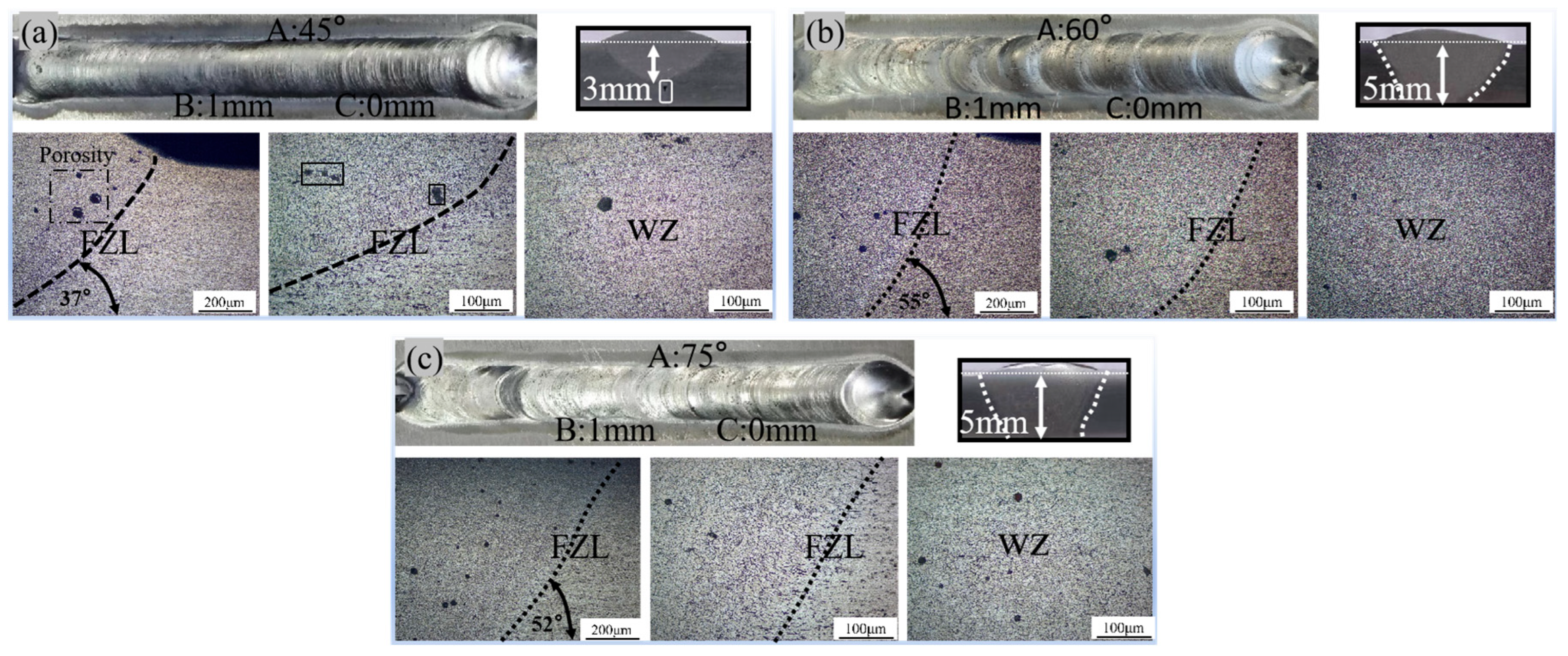
Figure 3, when controlling the size of the root face, and the reserved gap is unchanged, the groove angle has a significant effect on the weld depth and porosity distribution. When the groove angle is 45°, the cooling rate is faster, the local heat dissipation is intensified, and the gas cannot be diffused to the surface of the molten pool in time to escape and ultimately is captured by the crystal, leading to the formation of micro-scale porosity defects, resulting in the emergence of a larger number of larger porosities near the fusion line, the growth of an equiaxial crystal area downward, the weld depth of melting being only 3 mm, and the organization not being uniform. When the groove angle is increased to 60°, the molten pool mobility is improved; the weld depth reaches 5 mm and shows smooth, consistent bead morphology. The cross-section defects are significantly reduced, and only in the heat-affected zone and the center of the weld are a few porosities found. With the groove angle further increased to 75°, the minimum height of the front of the weld is 0.9 mm, the cooling rate is moderate, the gas escape is more adequate to achieve single-sided welding and double-sided molding, the cross-section did not see obvious defects, and the metallographic organization of the pores is small in size and in a uniform distribution.
It can be concluded that, when the groove angle is too small (45°), the arc heat input is concentrated on the upper surface of the plate, and part of the arc fails to penetrate deep into the interior of the groove, which results in the molten pool not completely melting through the plate, forming localized unfused defects. At the same time, the groove volume is small; the molten pool is subject to both sides of the groove inclined surface and the geometry of the V-shaped groove compression and extrusion effect, so that the molten pool mobility is reduced, the gas escape channel is blocked, and the gas dissolved in the molten pool cannot diffuse to the surface to escape. During the rapid cooling process, the gas solubility decreases dramatically, leading to the precipitation of gas at the grain boundaries and within the grain, forming more and larger porosity defects. At the crystal structure level, these porosities are mostly distributed near the fusion line, and the angle between the fusion line and the horizontal plane is the smallest (37°), which further limits the metallurgical bonding effect of the weld.
With the groove angle increased to 60°, the fusion line and the horizontal plane angle are increased to 55°, the melt pool geometric space increases, the arc goes more easily deeper into the inside of the groove, the heat distribution is more uniform, and the fluidity of the melt pool is significantly improved. At this time, the downward convection of the molten pool enhances the gas diffusion and escape more fully, there is the formation of a smooth fish-scale pattern of full penetration morphology, and the porosity defects are significantly reduced. When the groove angle was further increased to 75°, the fusion line angle (52°) was slightly reduced, but the welded joints realized one-side welding and two-side forming, and no obvious defects were found in the cross-section. The moderate fusion angle improves the heat transfer between the molten pool and the base material and promotes the metallurgical bonding of the crystalline structure, which improves the densification and mechanical properties of the weld [
13].
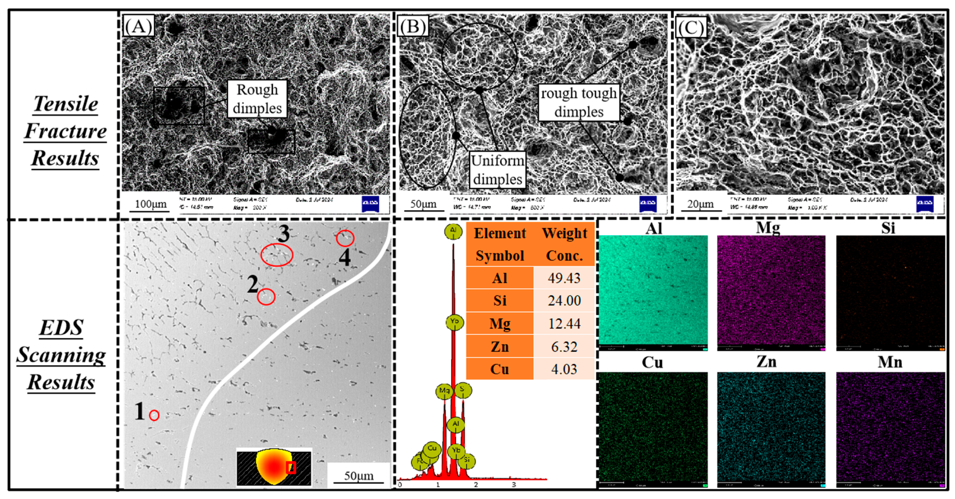
As a high-strength aluminum alloy, the main alloying element of Al7072 is zinc (Zn), which has a complex phase transition and microstructure evolution mechanism during the welding process. During the GTAW welding process, the precipitation phases in the weld seam of ER5356 wire are distributed in granular and chain form (as shown in
Figure 4), and the main phases include α-Al, β-AlFeMg, θ-Al
2Cu, β-Mg
2Si, and η-MgZn
2, etc. These precipitated phases significantly enhance the weld strength through solid-solution hardening and age hardening mechanisms, but they are also accompanied by the formation of brittle phases [
14]. During the welding process, the Mg element is susceptible to burnout due to high evaporation, and the supplementation of the Mg content in the ER5356 wire promotes the generation of β-Mg
2Si-strengthened phases, whereas η-MgZn
2 mainly originates from the base material Al7072. The increase in weld heat input at increasing groove angle exacerbated the vaporization of Zn and its redeposition in the cooled region, thus elevating the Zn content in the weld (as shown in the SEM surface scan in
Figure 4). The increase in Zn content in the weld promoted the generation of a MgZn
2-reinforced phase, which significantly increased the tensile strength and elongation at break of the weld by hindering the dislocation motion and optimizing the weld microstructure, which was highly consistent with the experimental results. This process reflects the coupled mechanism of heat input–matter transport-–tissue strengthening [
15].
In the metallographic organization, the grain size in the heat-affected zone (HAZ) increases compared to that of the base material, mainly due to grain re-growth caused by welding heat input and the formation of low melting point eutectics (e.g., AlFeSi) at the grain boundaries. These eutectics partially “self-heal” during cooling; however, the presence of brittle phases (e.g., AlFeSi and β-AlFeMg) reduces the fracture toughness and hardness of the alloy, resulting in the lowest microhardness of the HAZ [
16]. In addition, the θ(Al
2Cu)-strengthened phases together with grain boundary precipitation-strengthened phases (e.g., β-Mg
2Si and η-MgZn
2) enhance the strength of the weld through the solid-solution hardening mechanism but reduce the plasticity and toughness (as shown in
Figure 4, points 1–3) [
17].
Taken together, a reasonable groove angle (e.g., 60° or 75°) and appropriate root face design can balance the mobility of the molten pool and the metallurgical reaction rate, inhibit the formation of porosity defects, optimize the crystal structure and the distribution of reinforcing phases, and thus enhance the comprehensive performance of the weld. At the same time, through the regulation of heat input and groove geometry parameters, the heat-affected zone grain growth and brittle phase precipitation of Al7072 welded joints can be effectively controlled to ensure the strength, toughness, and stability of the joint [
18].
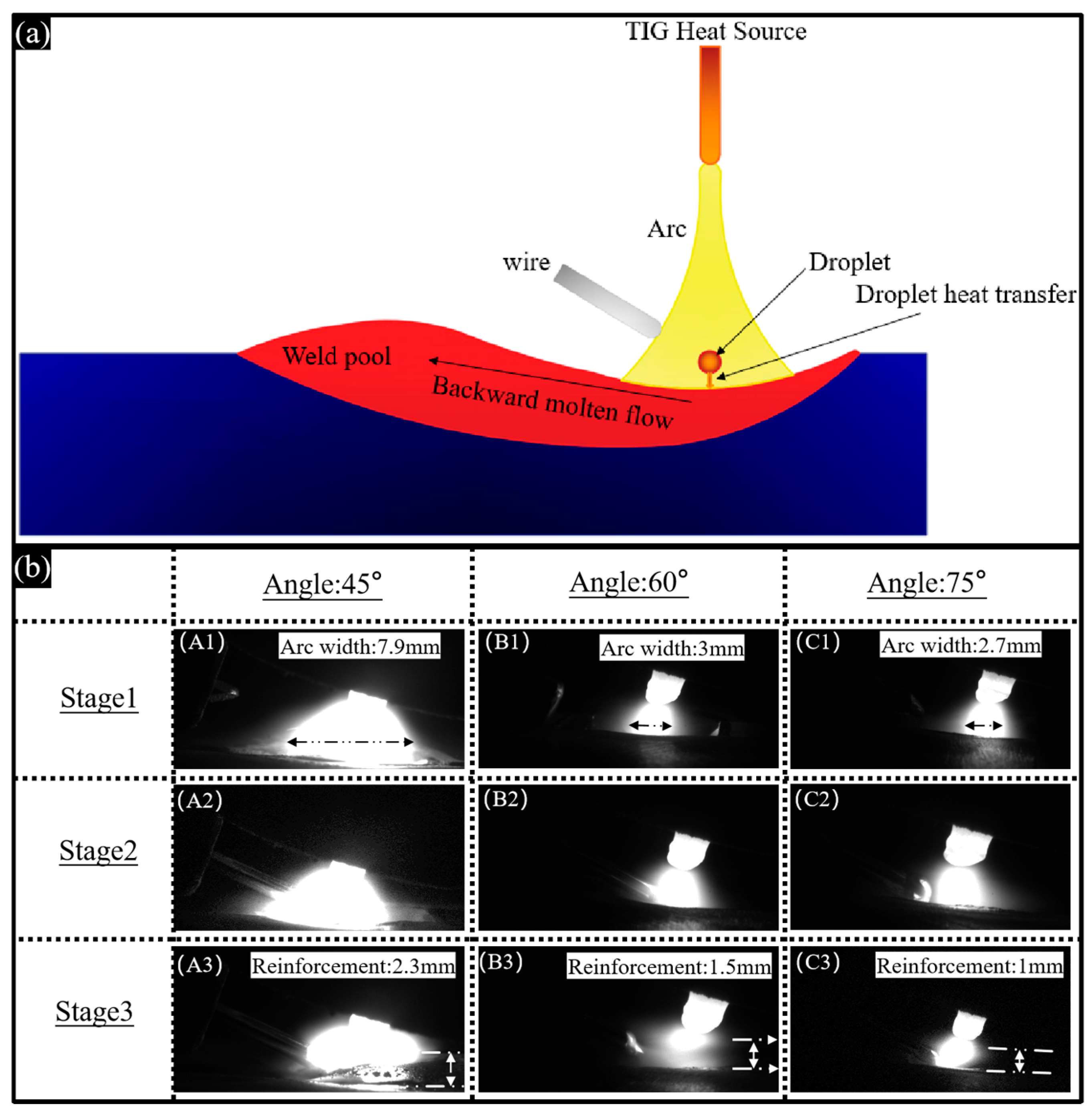
The welding molten pool undergoes three critical stages, the formation stage (stage 1), the stabilization stage (stage 2), and the solidification stage (stage 3), as shown in
Figure 5b. As can be seen from
Figure 5b, the groove angle has a significant impact on the arc distribution, melt pool flow, and weld forming quality. When the groove angle is small (45°), the arc is attracted by the top of the plate, and, according to the minimum voltage theorem, the arc tends to the shortest path and cannot penetrate deep into the groove, and the heat is distributed on the surface, and the arc width is the largest (7.9 mm). At this time, the volume of the melt pool is limited, and the geometric extrusion effect of the grooves on both sides further reduces the fluidity of the melt pool, and the gas escape channel is blocked, resulting in the dissolved gas in the melt pool not being able to diffuse to the surface in time to escape. In the process of rapid cooling, the solubility of the gas drops sharply, and the precipitated gas aggregates in the grain boundary and the grain, forming more and larger porosity defects, with the largest residual height (2.3 mm), insufficient weld penetration, and easy-to-produce defects such as non-fusion. As the groove angle increases to 60°, the arc gradually penetrates into the groove, the arc width shrinks to 3 mm, the heat distribution is more concentrated, the fluidity and downward convection of the molten pool are significantly enhanced, the molten droplets fill the root of the groove more evenly, and the residual height is significantly reduced to 1.5 mm. When the groove angle is further increased to 75°, the arc concentration is the largest, the melting position at the top of the groove side surface is reduced, the molten pool is enhanced by downward convection under the action of gravity, the penetration effect is better, the residual height is the smallest (1 mm), and the welded joint is single-sided welding and double-sided forming. In this case, the root face plays a critical role in controlling the penetration depth, preventing excessive heat input from causing burn-through of the plate, while maintaining the integrity and quality of the weld [
19].
With appropriate addition of the reserved gap, under the synergistic effect of the surface tension of the molten droplets and gravity, the metal liquid can flow freely and penetrate, further improving the effect of filling the molten pool. At the same time, the reserved gap can compensate for the dimensional changes caused by thermal expansion and cooling contraction during the welding process, reduce residual stress and microcracks, and improve the denseness and metallurgical bonding quality of the weld.
Taken together, the increase in groove angle optimizes arc heat distribution, improves molten pool fluidity and downward convection, and significantly reduces defects such as residual height and porosity. The synergistic regulation of the root face size and the reserved gap further balances the depth of penetration and heat input, suppressing the problems of burn-through and thermal deformation of the sheet. At the mechanism level, the groove parameter significantly improves the densification, strength, and stability of the weld by regulating the thermodynamic behavior of the molten pool, solid–liquid phase transition, and gas precipitation process, which provides a theoretical basis and practical guidance for the optimization of the welding process.
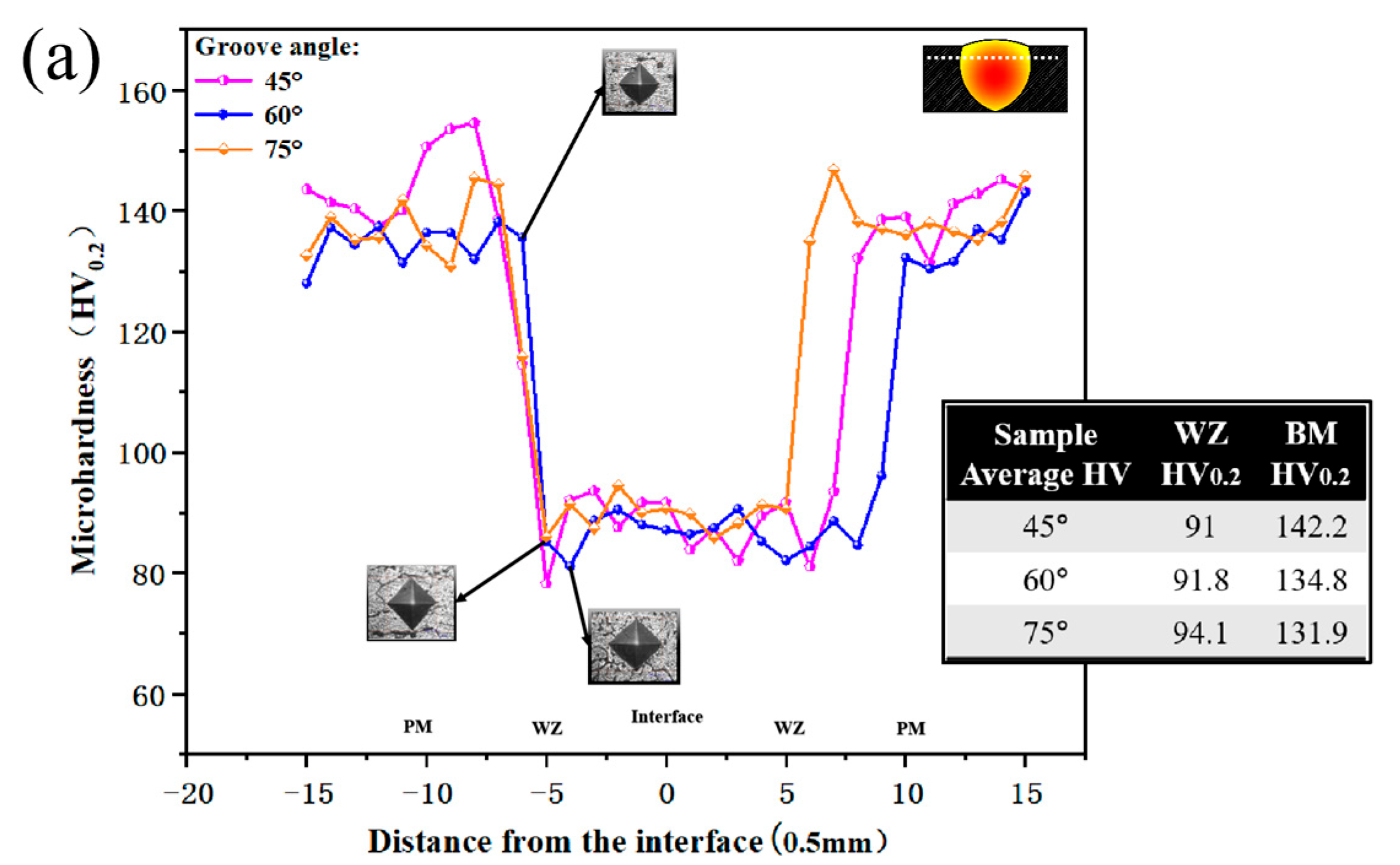
Figure 6a illustrates the hardness gradient across the cross-sections of welds with different groove angles, exhibiting a W-shaped hardness curve. For the joint with a 45° groove angle, the base metal exhibits the highest hardness, while the weld metal demonstrates the lowest. Conversely, for the 75° groove angle, due to the significant influence of arc heat, the hardness of the base metal decreases, but the hardness of the weld metal increases. The weld metal hardness distribution in joints with 60° and 75° groove angles is uniform, with minimal fluctuations. The 45° groove angle, due to its smaller groove inclination, significantly enhances the compressive effect on the molten pool, restricting its fluidity and leading to uneven heat distribution [
20].
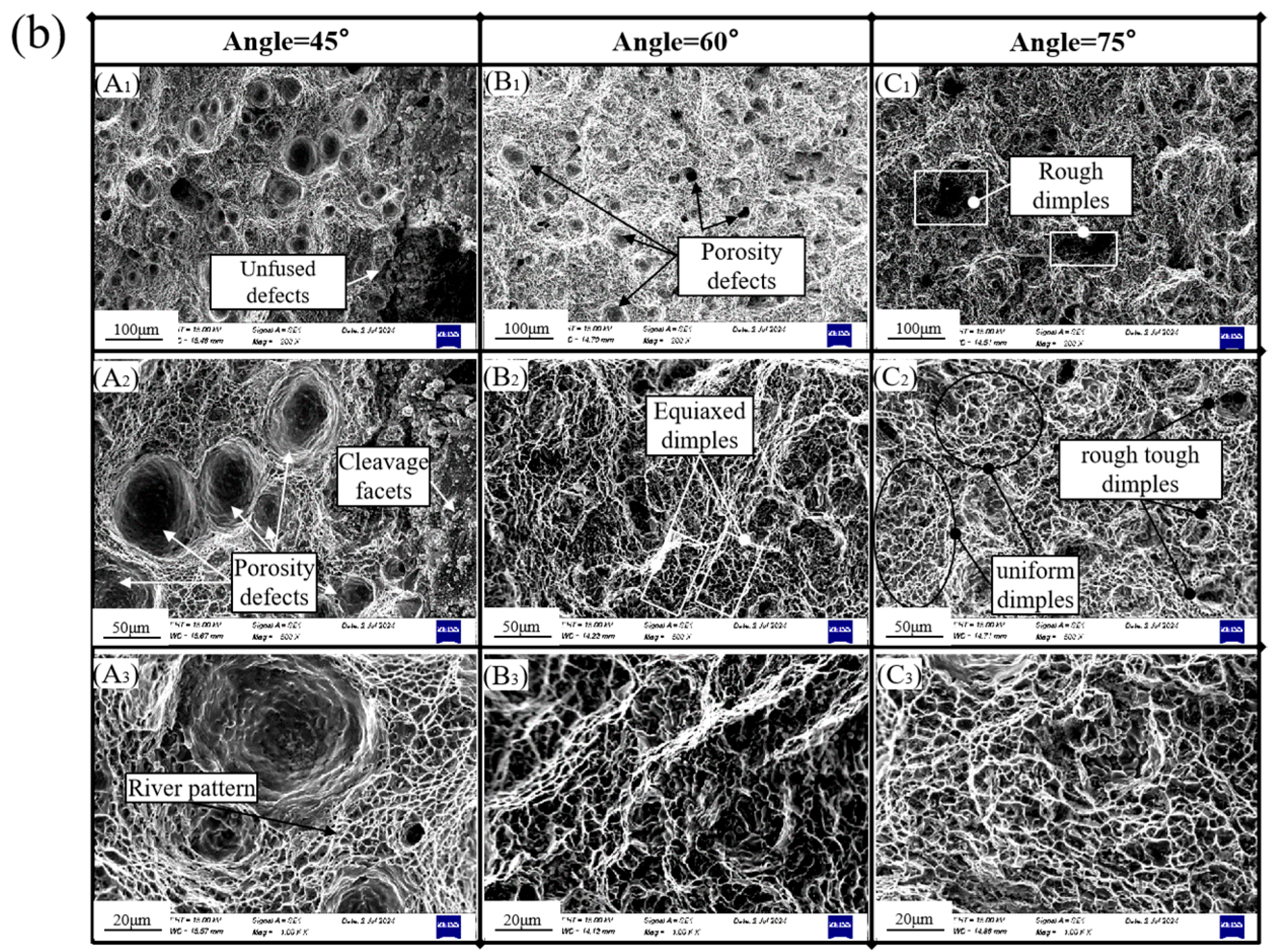
Figure 6b presents the tensile fracture morphologies. The fracture specimen from the 45° groove angle contains numerous large pores and quasi-cleavage planes, suggesting the possibility of brittle fracture (as shown in
Figure 6(bA1–bA3)). In contrast, the 60° groove angle fracture specimen exhibits fewer and smaller pores, along with large bands of equiaxed dimples, indicating good plasticity and toughness (as shown in
Figure 6(bB1–bB3)). The 75° groove angle fracture specimen has the fewest pores (as shown in
Figure 6(bC1–bC3)), featuring rough and deep dimples as well as fine and uniform dimple bands, primarily indicating ductile fracture. The tensile strengths are 170 MPa, 263.8 MPa, and 293.5 MPa, respectively, which align with the observed fracture morphologies. All tensile fractures occurred in the heat-affected zone (HAZ), as the tensile strength of the ER5356 welding wire is significantly lower than that of the 7072 base material. Additionally, the welding thermal cycling in this zone leads to microstructural coarsening, phase transformation embrittlement, residual stress concentration, and reduced toughness, resulting in a locally weakened area that becomes the preferred initiation site for fracture.
3.2. Influence of Root Face Height on Weld Quality
In welding, the purpose of the root face is to prevent the molten pool from melting through the base material while providing a smooth transition area. A root face height parameter that is either too large or too small can compromise the stability of the molten pool, particularly at the root. An unstable molten pool can hinder the ability of gas bubbles to break up and escape, leading to the formation of pores, cracks, and unfused defects within the joint [
21].
When the groove angle is set to 45°, with a 0.75 mm reserved gap and a 2 mm root face, the penetration depth is 2 mm. At the start of the root face, incomplete fusion is observed, and there are large pores at the top of the weld. The fusion angle is measured at 33°. When the root face is reduced to 1 mm, the penetration depth increases to 3.4 mm, with incomplete fusion still present at the top. The fusion angle remains at 32°, indicating that the root face has a minor impact on the fusion angle with a smaller groove angle.
For a groove angle of 60°, a 0.75 mm reserved gap, and a 1.5 mm root face, the number of pores decreases but their size remains large, with a penetration depth of 3.75 mm. This is due to the shortened existence time of the molten pool when the root face is too large, limiting the escape of gases, which then form pores during solidification. When the root face is reduced to 1 mm (
Figure 7d), the penetration depth increases to 4 mm, and the pores are significantly reduced. The fusion angle decreases to 32° (compared to 46° with a 1.5 mm root face). A smaller fusion angle can reduce welding deformation and heat input but may also increase the risk of defects. An appropriate fusion angle is crucial for achieving high-quality joints.
In summary, achieving an optimal root face is paramount for ensuring high-quality joints. When considering weld shaping, melting depth, and defect control, the parameter of a 1 mm root face, as depicted in
Figure 7d, emerges as the best choice. This configuration enhances melting depth, effectively minimizes porosity defects, optimizes molten pool stability, and elevates the overall quality of the welded joint.
As shown by the FM-800 measurements and subsequent analysis, the PM hardness rises in tandem with the increasing size of the root face, whereas the WZ hardness exhibits an inverse trend. An enlargement of the root face leads to a reduction in the groove area, which in turn decreases the cooling rate of the weld. This deceleration hinders the refinement of equiaxial crystals, ultimately causing a decline in WZ hardness. Simultaneously, as the root face increases, the initial distance between the heat source and the base material expands, reducing heat transfer efficiency. This helps preserve the hardness of the base material, resulting in a gradual increase followed by a decrease in hardness from the WZ through the HAZ. This variation is influenced by the inhomogeneous structure of the weld. Consequently, the hardness curve typically assumes a W-shape. Notably, an increase in the root face significantly diminishes the WZ hardness amplitude while enhancing the WZ width and hardness uniformity (as illustrated in
Figure 8(aA,aB)).
Figure 8b displays the tensile fracture morphologies for different root faces. In Group 1 (as shown in
Figure 8(bA1,bB1)), when the root face is 1 mm, the fractures are characterized by multiple porosity defects, with a small number of ductile dimple areas visible at the bottom (see
Figure 8(bA2) for details). All the welded joints in this group exhibit incomplete fusion issues. However, when the root face increases to 2 mm, welding slag inclusion occurs (as shown in
Figure 8(bB1)), a defect that significantly weakens the tensile strength, plasticity, and toughness of the weld. Upon further examination of the fracture at 500× magnification (
Figure 8(bB2)), rough and large ductile dimples are visible, indicating an adverse effect on the ductility and toughness of the joint.
In Group 2, the tensile fractures of both sets of specimens occurred in the HAZ; the tensile fracture observed at a 1.5 mm root face exhibited large and deep porosity defects, with rough and prominent dimples in the center (as shown in
Figure 8(bC1–bC3)). Across all the joints, unfused issues were prevalent. However, when the root face was 1 mm, a fine dimple bands strip was present at the junction of the weld and base metal. Under 500× magnification, small and uniform dimple bands were visible, potentially resulting from uneven plastic deformation during the tensile process. The size of the root face had a significant impact on tensile strength, with the experimental groups recording tensile strengths of 166.5 MPa and 156.5 MPa (Group 1) and 247.65 MPa and 251.11 MPa (Group 2), respectively. A properly blunted root face prevents fusion penetration and ensures weld stability, while an excessively large root face leads to unfused (defective) welds. The tensile strength and tensile fracture morphology characteristics of the experimental groups were highly consistent, confirming the crucial influence of root face on weld quality.
3.3. Influence of Reserved Gap on Weld Quality
A reasonable reserved gap helps minimize thermal stresses and deformations during the welding process, allowing the weld pool to expand more freely into the reserved gap without exerting excessive thermal influence on the workpiece. Reserving an appropriate reserved gap compensates for the dimensional changes in the base material due to thermal expansion, thereby ensuring welding quality [
22].
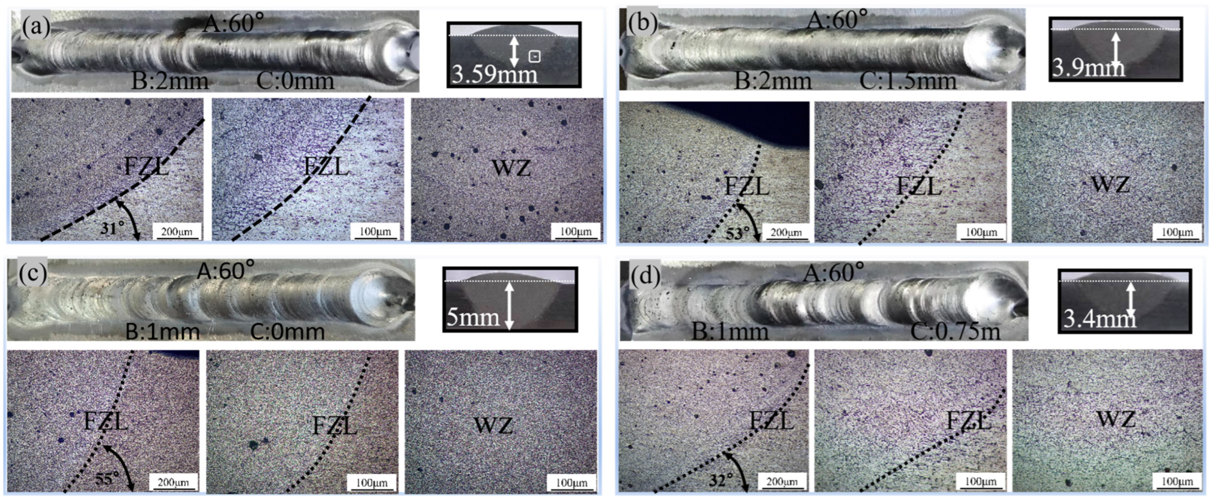
When comparing the joints in
Figure 9a,b, which feature a groove angle of 60° and a root face of 2 mm, the welded joints exhibit satisfactory forming quality. However, they do possess unfused defects, suggesting inadequate melt pool fluidity and filling. Upon increasing the reserved gap to 1.5 mm, the depth of fusion increased from 3.59 mm to 3.9 mm, the fusion angle expanded from 31° to 53°, the stability of the molten pool significantly improved, and porosity defects were greatly diminished. In the scenario featuring a groove angle of 60° and a root face of 1 mm, achieving full penetration is observed when the reserved gap is set to 0 mm. This results in a fusion depth of 5 mm, an optimized fusion angle of 55°, minimal porosity content, and exceptional weld density and forming effects. Conversely, increasing the reserved gap to 0.75 mm leads to a decrease in fusion depth to 3.4 mm, a narrowing of the fusion angle to 32°, and an increase in porosity. This suggests that an excessively wide reserved gap causes heat dispersion and impedes melt pool flow, compromising penetration and defect control.
Hence, widening the reserved gap when dealing with a large root face promotes stable flow of the molten pool, boosts penetration, minimizes porosity, and enhances joint quality. Conversely, in the case of a small root face, an excessively large or mismatched reserved gap leads to heat loss from the molten pool, compromising fusion quality. Therefore, in this paper, the BBD method is used to optimize the groove parameters in order to enhance the depth of fusion and tensile strength.
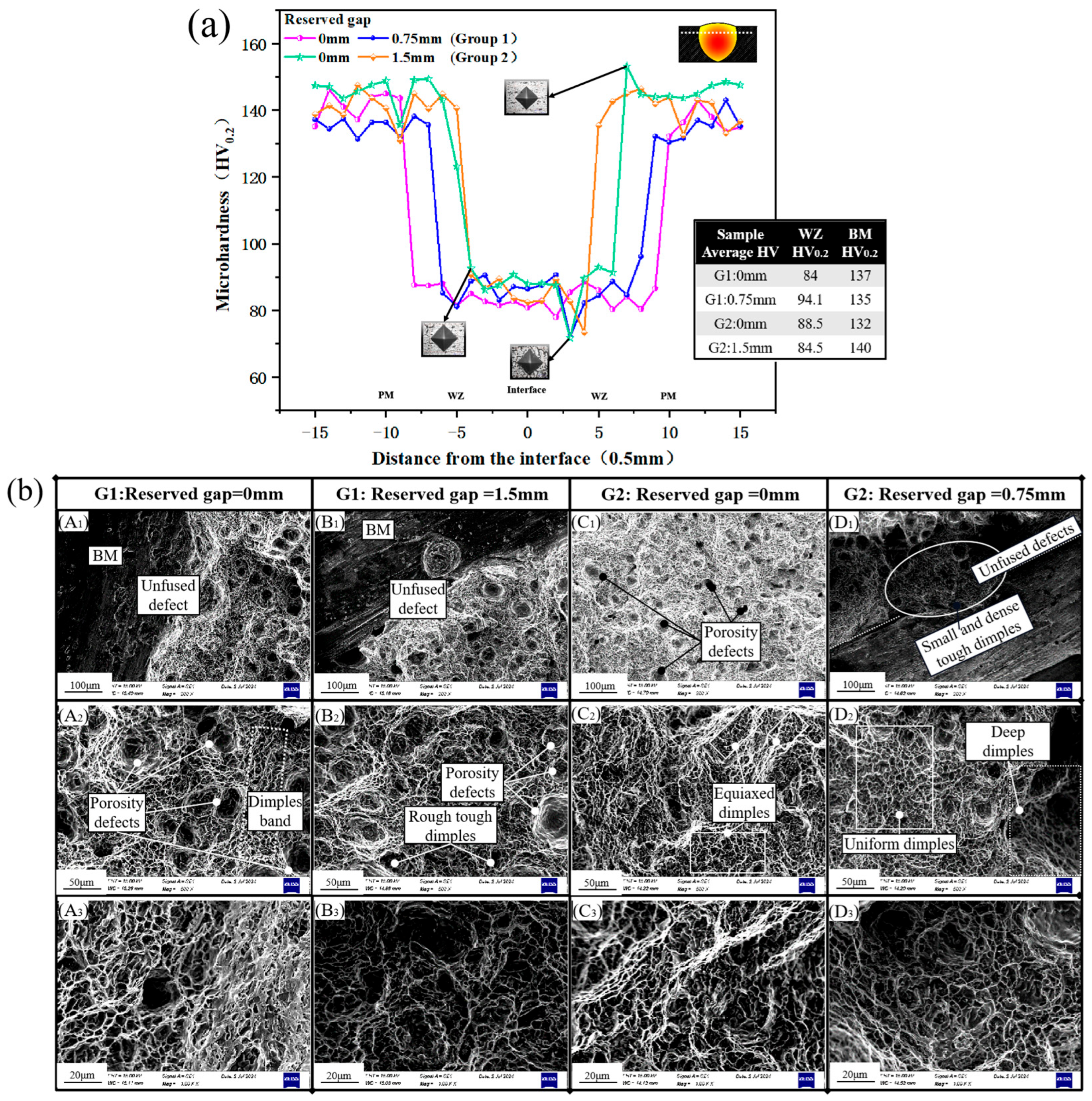
Figure 10a illustrates that the relationship between the reserved gap and microhardness is nonlinear. Specifically, the highest average hardness of 94.1 HV
0.2 was recorded for the weld zone (WZ), with a reserved gap of 0.75 mm, while the average hardness for the parent metal (PM) was 136 HV
0.2. A moderate increase in the reserved gap to 0.75 mm enhanced the microhardness of the WZ. However, an excessive enlargement of the reserved gap to 1.5 mm resulted in a decrease in microhardness. As previously discussed, a moderate reserved gap can effectively compensate for the dimensional changes due to thermal expansion during welding, thereby enhancing the overall performance of the welded joint. Conversely, an excessively large reserved gap can lead to welding omission, manifesting as unfused defects in parts of the weld, which ultimately compromises weld quality.
Figure 10b displays the morphology of tensile fractures observed with varying the reserved gap. In Group 1, fine dimples bands and large air holes are evident when the reserved gap is 0 mm (as shown in
Figure 10(bA1–bA3)). As the reserved gap increases to 1.5 mm (as shown in
Figure 10(bB1–bB3)), the number of air holes rises, and the dimples becomes rough. In Group 2, with a 0 mm gap (as shown in
Figure 10(bC1–bC3)), numerous small air holes are present, and SEM images at 500× magnification reveal microvoids, indicative of good plasticity and toughness. When the gap is 0.75 mm (as shown in
Figure 10(bD1–bD3)), fine dimples strips are visible in the center, accompanied by unfused defects. The large dimples in the lower left end are densely populated with smaller dimples, potentially resulting from the unique role of uneven plastic deformation during aluminum alloy stretching. The tensile strength data for the reserved gap parameter groups (Group 1 and Group 2) are 253.2 MPa and 263.8 MPa (Group 1) and 229.05 MPa and 251.11 MPa (Group 2), respectively. These results suggest that selecting an appropriate reserved gap can significantly reduce porosity defects and their sizes, thereby enhancing the depth of fusion to a certain extent. Conversely, an excessively large reserved gap leads to poor fusion of the joint, which aligns with the morphological characteristics of the tensile fracture, further confirming the crucial impact of the reserved gap on weld quality.


