Abstract
Titanium alloy/carbon fiber-reinforced polymer (TA1/CFRP) laminates, representing the latest fourth generation of fiber metal laminates (FMLs), is a kind of high-performance composite material. However, the fragility of the fiber/resin and metal/resin interface layers in these composites directly impacts their mechanical properties. To enhance these properties, this paper investigates the preparation process of multi-walled carbon nanotube (MWCNT)-reinforced ultra-thin TA1/CFRP laminates and explores the impact of MWCNT content on the interlayer properties of these ultra-thin TA1/CFRP laminates. Initially, the challenge of dispersing carbon nanotubes using ultrasonic dispersion devices and dispersants was addressed. Vacuum-curing pressure studies revealed minimal overflow at 0.8 bar vacuum. Subsequently, the impact of MWCNT content on interlayer properties was investigated. The results indicated a significant increase in interlayer shear strength and interlayer fracture toughness with MWCNT additions at 0.5 wt% and 0.75 wt%, whereas the interlayer properties decreased at 1.0 wt% MWCNT. Fracture morphology analysis revealed that MWCNT content exceeding 0.75 wt% led to agglomeration, resulting in resin cavity formation and stress concentration.
1. Introduction
Fiber metal laminates (FMLs) are ultra-hybrid structures composed of multiple alternating layers of metal sheets and fiber-reinforced resin prepregs [1,2,3]. Compared to traditional metals and composites, FMLs offer a combination of lightweight properties, high strength, superior fatigue and impact resistance, and exceptional durability in wet and hot environments [4,5,6]. As the latest fourth-generation FMLs, ultra-thin titanium alloy/carbon fiber-reinforced polymer (TA1/CFRP) laminates exhibit remarkable high impact resistance and rigidity [7]. However, FMLs exhibit significant differences in heterogeneous component performance and possess complex interface systems. The failure of FMLs primarily include interlaminar failure, resin matrix fracture, metal fracture, and synergistic fracture [8,9,10]. The fiber/resin and metal/resin interface layers are relatively fragile, and the bonding quality of each layer directly affects the mechanical properties of the laminates [11,12]. Hance-enhancing interlayer properties is crucial.
Since the 1980s, with the development of nanotechnology and the emergence of nanocomposites, polymer/nanocomposite materials have attracted global attention due to their outstanding comprehensive performance [13,14]. Introducing nanoparticles into a polymer matrix can significantly enhance the performance of fiber-reinforced polymers [15,16,17]. Carbon nanotubes, as isomers of C60, are seamless nanostructures formed by the curling of single-layer graphite, exhibiting high aspect ratios and stable performance, among other advantages [18,19]. When carbon nanotubes are uniformly dispersed in the resin matrix, their excellent performance allows them to withstand loads far beyond those of the resin matrix alone [13,14,17]. Therefore, by adding an appropriate amount of carbon nanotubes, the performance of the resin composite matrix can be significantly improved [20,21,22].
Konstantakopoulou et al. [23] have studied the effects of surface treatment methods and the mass fraction of MWCNT on these variables, revealing that among all specimens with added MWCNT, those treated with anodization exhibited the highest interfacial strength. After interfacial property tests on specimens with the same surface treatment, those with 0.1 wt% and 0.3 wt% MWCNT content showed higher interfacial strength. Tiny pores formed on the aluminum alloy surface after anodic oxidation. This allowed better resin impregnation of the metal surface, forming a tight mechanical lock and improving the interlaminar properties of the laminate. Khurram et al. [24] have investigated the influence of different mass fractions of MWCNT on the properties of Al2024 and glass fiber-reinforced epoxy resin laminates (GFRE). The results indicated that under atmospheric pressure, adding varying amounts of MWCNT did not increase the bond strength of the samples. However, applying vacuum pressure during the curing process resulted in a certain trend. In this case, the MWCNT content could be increased to 2.0 wt%, with the sample strength rising accordingly. But beyond this value, adverse effects were observed. Khoramishad et al. [25] investigated the high-speed impact and tensile properties of FMLs with different mass fractions of MWCNT. The results indicated that by adding MWCNT into the polymer matrix, significant suppression of relevant damage to composite components could be achieved. Aghamohammadi et al. [26] investigated the impact of COOH-functionalized MWCNT on the bending and high-speed impact properties of FMLs. The results revealed an enhancement trend in the bending performance of the samples with increasing MWCNT content, attributed to the improved interfacial adhesion due to the addition of MWCNT. Yu et al. [27] have utilized mechanical stirring combined with ultrasonication to prepare MWCNT-epoxy resin composites as adhesives, incorporating varying amounts of MWCNT to enhance the adhesion between aluminum plates. The experimental results indicated that the addition of MWCNTs in the polymer matrix significantly affected the fracture toughness of the specimens, and MWCNTs played a positive role in enhancing this property. Fracture toughness increases as the MWCNT content in the epoxy matrix rises to 1.0 wt%. However, for specimens with higher MWCNT content, the reinforcing effect diminishes. At high concentrations, MWCNTs can become defects in FMLs, leading to a degradation of the mechanical properties of the specimens.
In summary, there exists an optimal range of MWCNT content for enhancing FMLs, whereby the judicious addition of nanomaterials can bolster both interfacial bonding and mechanical properties. Current research predominantly concentrates on the macro scale, with limited investigation into the microscale enhancement of FMLs by nanomaterials. This paper delves into a method for MWCNT-reinforced ultra-thin TA1/CFRP laminates at the micro scale. Initially, the focus lies on laminates preparation, using ultrasonic devices and dispersants and utilizing acetone as an intermediary solvent to address nanoparticle dispersion challenges in epoxy resin. Further investigations will be conducted to elucidate the mechanism by which MWCNTs affect the interlayer properties of ultra-thin TA1/CFRP laminates. An understanding of this mechanism has the potential to expand the scope of applications for FMLs in micro-forming and microelectronics.
2. Materials Preparation
2.1. Preparation of Prepreg Containing MWCNT
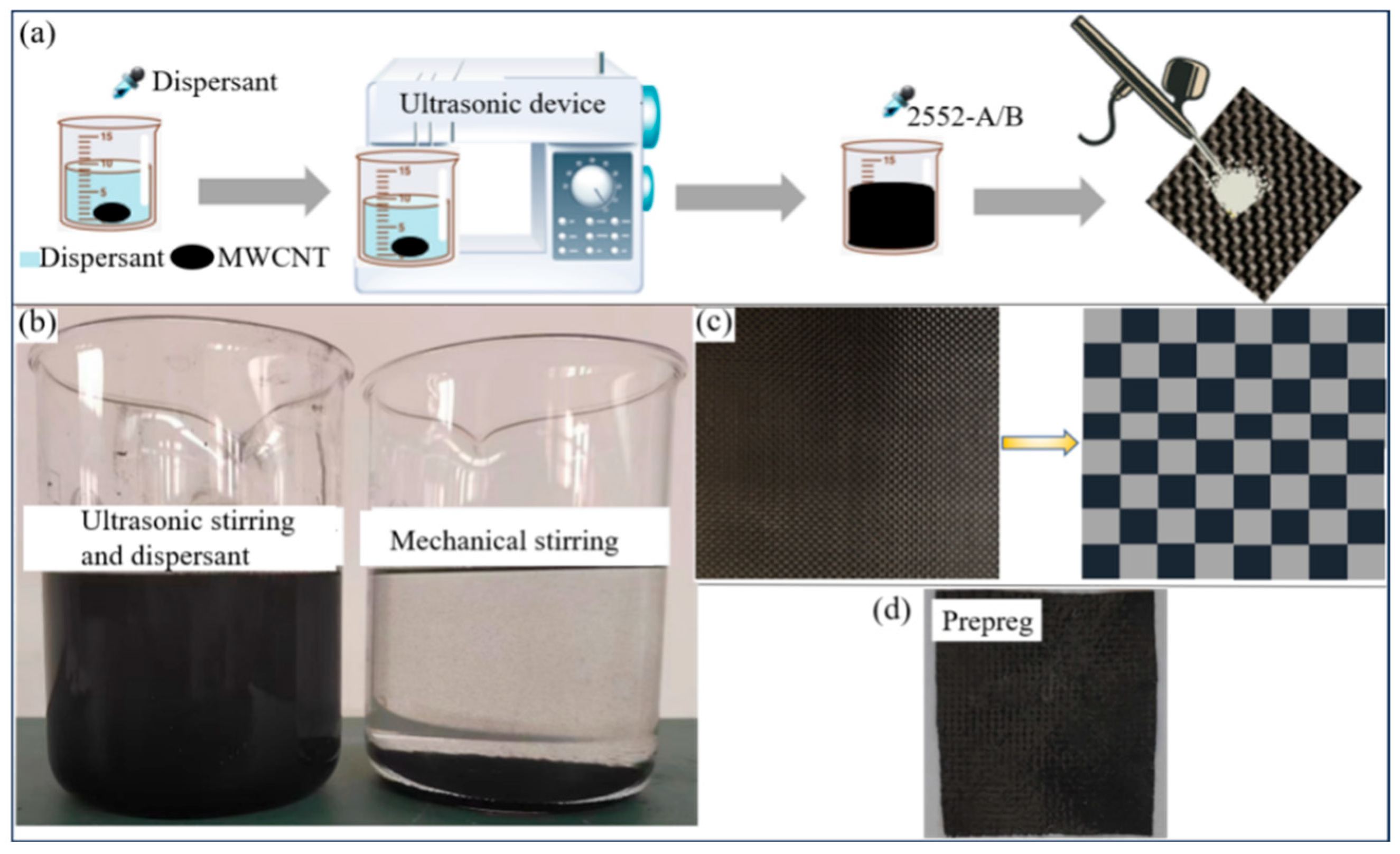
As seen in Figure 1a, a certain amount of MWCNT was proportionally weighed and dissolved in an acetone solution. Following this, a specific amount of dispersant was added. Subsequently, the mixture underwent ultrasonic stirring for 30 min in a separate cold bath within an ultrasonic device, facilitating MWCNT dispersion. The curing agent and epoxy resin outlined in Table 1 were combined at a 120:1 ratio. The prepreg formation ensued with the addition of the dispersion solution. Detailed specifications of the test materials are provided in Table 1, while Table 2 outlines the equipment employed for testing.

Figure 1.
Preparation process of prepreg containing MWCNT, (a) preparation of acetone–epoxy resin mixed solution containing MWCNT by ultrasonic dispersion, (b) dispersion of acetone–epoxy resin solution containing MWCNT after 7 days, (c) plain woven carbon fiber cloth, and (d) carbon fiber prepreg after pre-heating.

Table 1.
Main raw materials for prepreg preparation.
Table 2.
Main equipment.
The MWCNT acetone–epoxy resin solution, subjected to the procedures delineated in Figure 1b, demonstrates uniform suspension of MWCNT in the acetone solution following 7 days of mechanical stirring and static treatment. This indicates that the combination of ultrasonic dispersion and dispersant treatment achieves homogeneous dispersion of MWCNT in the solution.
The prepreg preparation methods are categorized into wet and dry methods. In this study, the wet method is employed, primarily involving the uniform dissolution of resin with an organic solvent to wet the fiber cloth, followed by evaporation of the solvent. The resin matrix utilized herein is a homogeneous mixture of acetone resin, evenly impregnated into the standard carbon fiber cloth depicted in Figure 1c via electrojet. The fibers are arranged on release paper and repeated five times on each side. Following impregnation, the fibers undergo 15 min of heating and ventilation in an oven. As acetone is volatile under heating conditions, it is removed from the prepreg via heating and evaporation. Once the carbon fiber prepreg depicted in Figure 1d is obtained, it is wrapped in release paper and set aside.
2.2. Surface Treatment of Titanium Alloy Foils
In order to enhance the interfacial strength between the TA1 titanium foil and the prepreg, the surface of the TA1 titanium foil is subjected to a series of sanding treatments using sandpaper with grits of 500, 800, and 1200. Following sanding, the metal surface is wiped with 95% alcohol to eliminate oil and particle residue. As depicted, the surface of the untreated TA1 layer in Figure 2a appears smooth and flat, whereas the irregular grooves created by sandpaper abrasion on the metal surface in Figure 2b facilitate close mechanical contact with the resin.
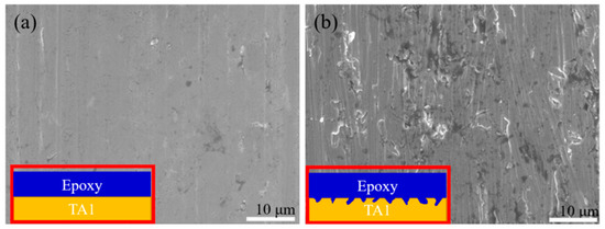
Figure 2.
Morphology of TA1 after different surface treatments, (a) untreated, and (b) sanding.
2.3. Curing of TA1/CFRP Laminates
The experiment adopts the vacuum bag oven curing method, utilizing materials as depicted in Table 3. All materials are supplied by EasyComposites. The shared use of a release agent and release cloth prevents the laminate from adhering to the vacuum bag, ensuring better surface quality of the laminate by preventing glue spillage. Furthermore, a breathable pad felt serves to prevent epoxy backflow during vacuum curing, thus safeguarding vacuum joints from damage caused by glue spillage.
Table 3.
Layered curing experimental materials.
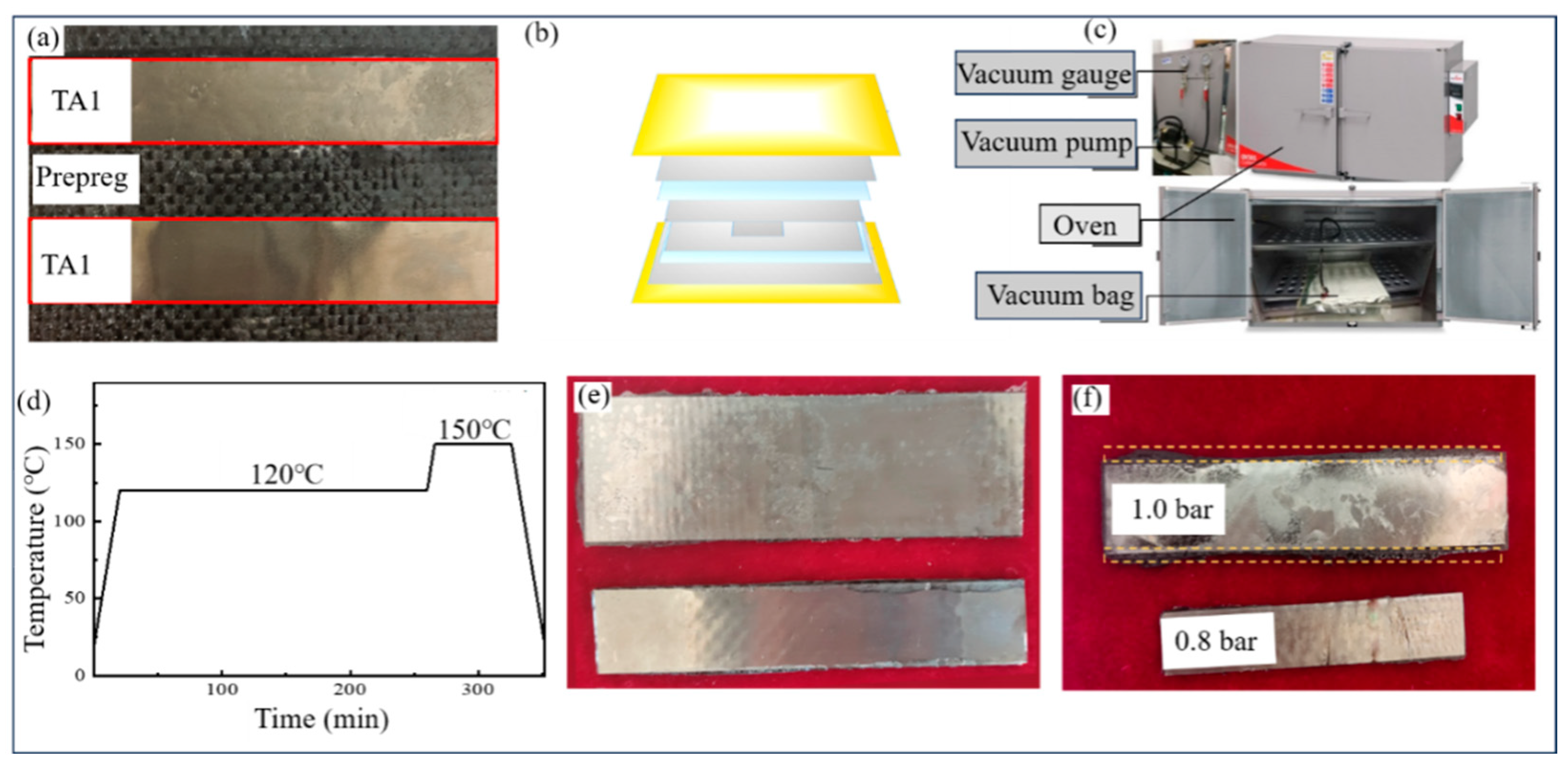
As illustrated in Figure 3a, the cut metal adheres to the prepreg surface in the rolling direction, aligning with the angle of the fiber. A scraper is employed to eliminate air bubbles between the metal plate and the prepreg. A TA1 plate served as the release mold, with the specimen positioned on a metal plate. Easy-Lease release agent was applied to both the inside and outside of the metal plate, and heat was applied for evaporation through the oven. The process was repeated three times to ensure even distribution of the release agent on the surface of the metal plate.
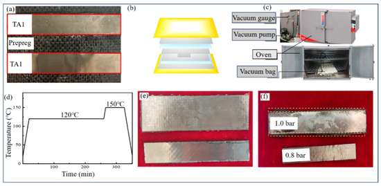
Figure 3.
Curing process of TA1/CFRP laminates, (a) metal laying on prepreg, (b) ultra-thin FMLs in a vacuum bag, (c) vacuum-curing device, (d) curing temperature curve of fiber metal laminate, (e) surface morphology of cured laminates under different pressures, and (f) ultra-thin FMLs with MWCNT.
Once the laying of ultra-thin FMLs is completed, they are placed within a vacuum bag, with the arrangement depicted in Figure 3b, comprising the specimen, metal plate, release cloth, breathable pad, and vacuum bag arranged from the inside out. The vacuum bag is then connected to the vacuum pump, ensuring that the vacuum pump maintains a vacuum degree of 0.8 bar. Excessive pressure during heating could result in significant epoxy resin overflow, thereby adversely affecting laminate performance. As illustrated in Figure 3f, the fiber–metal laminates cured under vacuum degrees of 0.8 bar and 1.0 bar reveals a notable difference. Within the yellow dashed line range, considerable epoxy resin overflow is evident along the specimen’s edges at 1.0 bar, whereas minimal epoxy resin overflow is observed at 0.8 bar, resulting in satisfactory specimen performance. These findings underscore the necessity of controlling the vacuum degree to achieve optimal adhesive properties and surface quality of the laminate. Consequently, subsequent experiments in this study will maintain a vacuum degree of 0.8 bar.
Heating and curing are conducted using the OV301 precision composite oven, as depicted in Figure 3c, with temperature control managed via the CN7-B software interface, illustrated in Figure 3d. It is crucial to maintain the vacuum at 0.8 bar during curing; therefore, the vacuum pump should be activated first to sustain the required vacuum level. The resulting ultra-thin FMLs specimen obtained through these procedures is displayed in Figure 3e.
3. Experimental
3.1. Experimental Equipment
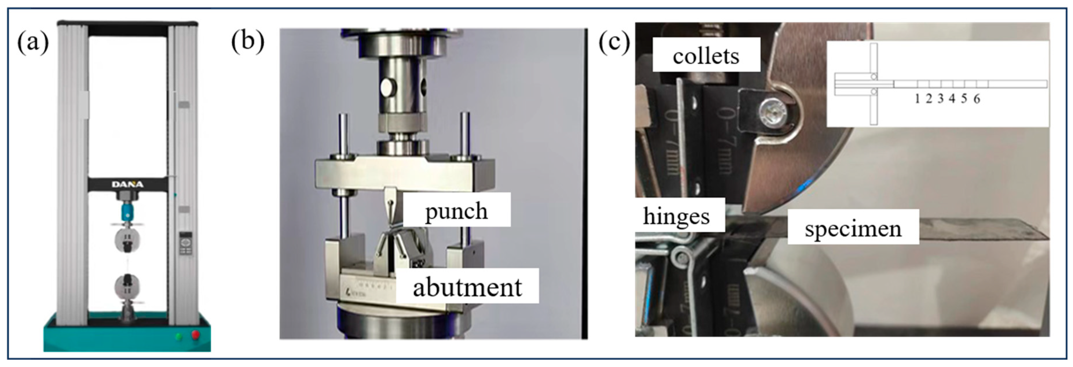
The test was conducted using the double-column digital display tensile testing machine shown in Figure 4a, with a maximum test force of 20 kN, force accuracy of 0.5 N, displacement resolution of 0.01 mm, and a range of beam movement speeds from 0.05 mm/min to 500 mm/min. For the interlayer shear strength test, the short beam shear test platform shown in Figure 4b was installed. The circular radius of the support base at the bottom of the test device was 5 mm, with the distance between the two supports corresponding to the specimen span, and the circular radius of the punch was 3 mm. The test data was automatically exported by the digital operating system to generate load–displacement curves. In the interlayer fracture toughness test, a low-resolution program was employed to ensure more accurate load values. As depicted in Figure 4c, a hinge-bonded clamping method was utilized. The 0.04 mm-thick titanium plate, polished with sandpaper, and the plain weave carbon fiber prepreg containing MWCNT were placed in a vacuum-curing oven. Cracks were pre-fabricated using an aluminum alloy film, which must not exceed 0.05 mm in thickness and must be leveled. Excessive thickness of the film may affect the test results by bonding with the epoxy resin overflow during curing. Meanwhile, during the test, the software automatically zeroed the load–displacement values to eliminate the influence of the specimen’s gravity. Upon reaching the observation point, displacement and load at each point were automatically recorded and unloaded at a predetermined speed. Due to the ultra-thin nature of the laminates, observing crack extension positions was challenging. Therefore, a high-magnification camera was installed at the same height as the specimen to record crack propagation during loading, enabling observation of small crack extension.

Figure 4.
Experimental equipment, (a) double-column digital display tensile testing machine, (b) short beam shear test device, and (c) double-arm suspension beam experimental device diagram.
3.2. Interlayer Shear Strength Test
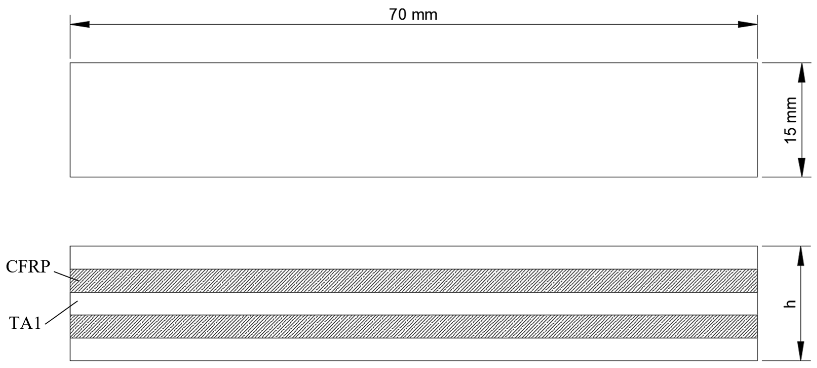
The interlayer shear strength tests were conducted using cured laminate specimens for comparative analysis. MWCNT mass fraction served as the variable, with each test set performed three times to obtain an average value. The tests were conducted at room temperature, and specimens were cured once under identical conditions to minimize errors. The laminates were composed of plain weave carbon fiber cloth pre-impregnated with resin, as described in Section 2, combined with 0.04 mm TA1 metal sheets to form a 3/2 structure of carbon fiber/titanium alloy laminates. The specimens adhered to the dimensions specified in the GB/T 35100-2018 composite short beam shear test standard, with TA1 material measuring 70 mm in length and 15 mm in width, as depicted in Figure 5. The allowable thickness deviation was ±5% of the average thickness. During testing, the radius of the supports did not exceed 5 mm, and the radius of the punch did not exceed 3 mm. Given the susceptibility to interlayer failure at small span-to-thickness ratios, a span-to-thickness ratio of 8 (L/h) was employed for the tests.
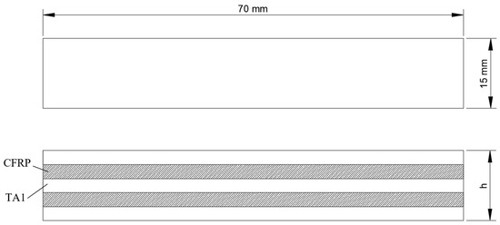
Figure 5.
Size of short beam shear test specimen.
The trial was divided into four groups with MWCNT mass fractions of 0.0%, 0.5%, 0.75 wt%, and 1.0 wt%, respectively, as shown in Table 4. The damage modes of the test samples were categorized into shear failure, compression deformation, and mixed failure. Shear strength was calculated according to Equation (1) and was derived from the mean of three sets of experiments:
where is the interlaminar shear strength, MPa; F is the maximum breaking load, N; b is the width of the specimen after curing, mm; and h is the thickness of the specimen after curing, mm.
Table 4.
Short beam shear test design.
3.3. Interlayer Fracture Toughness Test
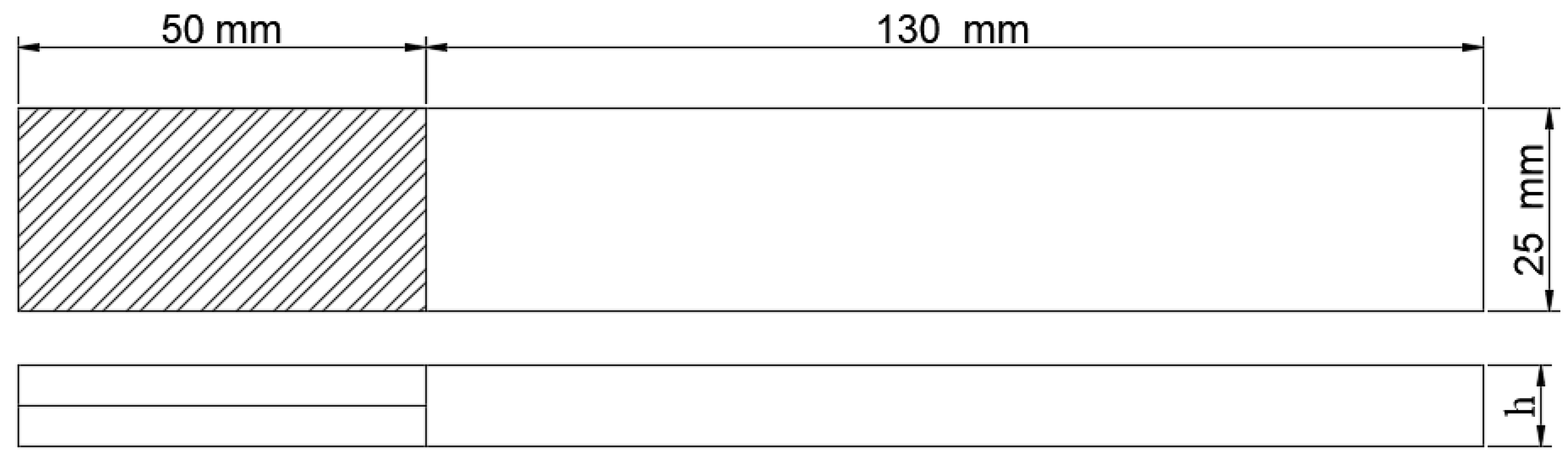
According to the GB7402-96 carbon fiber composite material type I fracture toughness test method, the specimen has a length of 180 mm and is of 2/1 type fiber–metal laminates. The pre-crack length at the test end is 50 mm. To achieve pre-cracking, aluminum foil with a thickness of 0.02 mm is inserted into the laminate during curing. The hinge is bonded to the test end using room temperature curing adhesive and secured with a fixture for testing. During specimen mounting, it is essential to ensure that the hinge is subjected to load at its center, with the intersection point of the hinge axis and the crack serving as the initial observation point. The test is stopped when the crack extends to 20 mm, with measurements taken every 10 mm thereafter until reaching the final observation point. The loading rate for the test is 3 mm/min, while the unloading rate is 10 mm/min. The testing specimen is shown in Figure 6. The calculation formula for type I fracture toughness is given by Equation (2), with six observation points per test set:
where GΙC is the type Ι fracture toughness of the laminate, J/m2; P is the crack extension critical load, N; δ is the displacement corresponding to the crack extension observation point, mm; W is the width of the specimen, mm; and α is the crack length, mm.
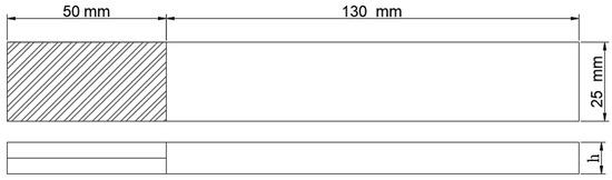
Figure 6.
Schematic diagram of dimensions of double-arm suspension beam specimen.
4. Results and Discussion
4.1. Effect of MWCNT Content on Shear Strength
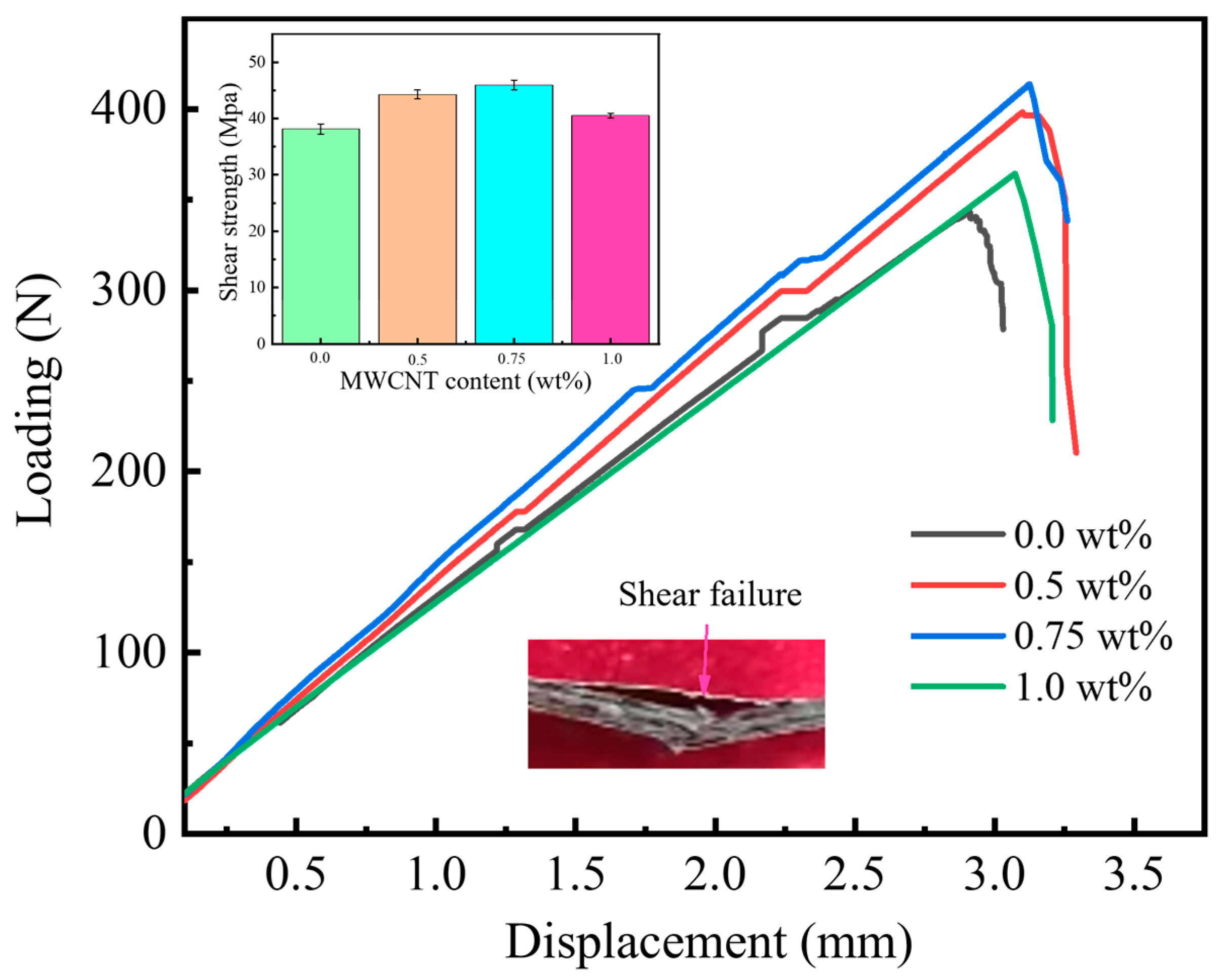
The load–displacement curves of carbon fiber/titanium alloy slab short beam shear tests with varying MWCNT addition content are depicted in Figure 7. It is evident from the diagram that upon adding MWCNT, the curve exhibits the standard interlaminar shear failure mode, characterized by linear load increase with displacement until reaching a peak value, followed by a sudden drop indicating interlaminar shear failure. With further displacement increase, the interlaminar failure area of the laminate enlarges. The peak loads of laminates with 0.5 wt% and 0.75 wt% MWCNT addition were higher than those without addition and with 1.0 wt% content, suggesting an enhancement in interfacial properties within an appropriate range. Nevertheless, at concentrations exceeding 0.75 wt%, agglomeration of carbon nanotubes may result in a reduction in peak load, as ultrasonic vibration is unable to break up the agglomeration or dispersed carbon nanotubes may re-agglomerate during prepreg fabrication.
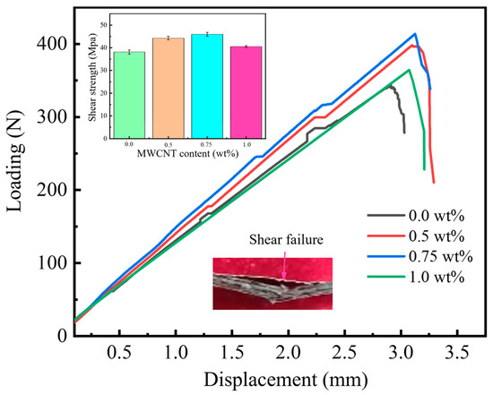
Figure 7.
Short beam shear test results: load–displacement curve and shear strength of specimens.
As observed in Figure 7, the addition of 0.5 wt% carbon nanotubes increased shear strength by 15.9% compared to the pure epoxy resin matrix, indicating an improvement in the interfacial shear strength of carbon fiber/titanium alloy laminate. However, the shear strength of the 1.0 wt% MWCNT sample was 9.6% lower than that of the 0.5 wt% MWCNT sample, attributed to partial agglomeration of MWCNTs in the resin matrix and stress concentration during loading. The shear strength of the specimens exhibited an initial increase followed by a decrease, with shear strengths nearing 44.25 MPa and 45.97 MPa, respectively, at 0.5 wt% and 0.75 wt% content.
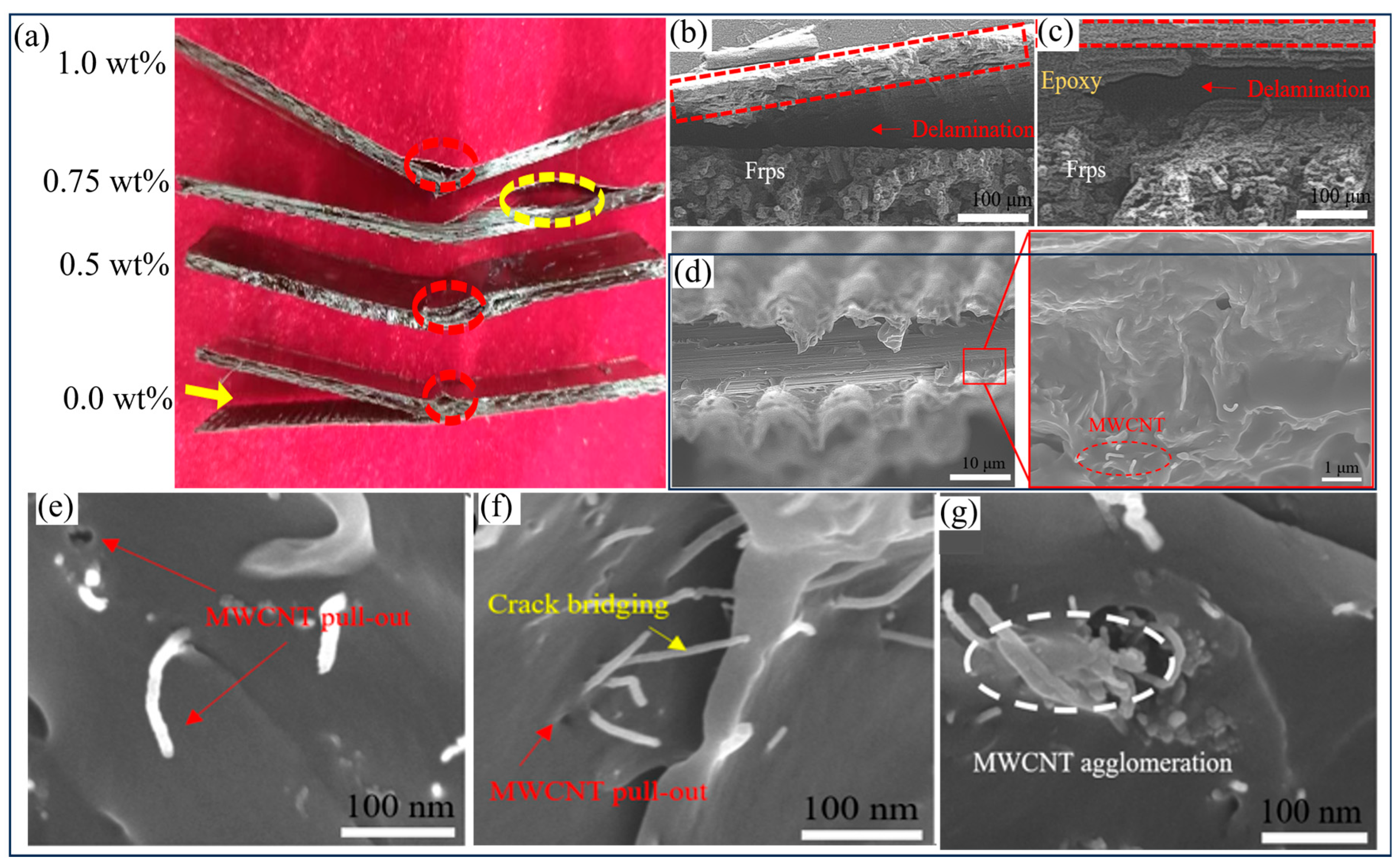
In Figure 8a, the failure of the laminates after the interlayer shear test is depicted. For the sample with a pure epoxy resin matrix, severe delamination occurred post-shear test, demonstrating a mixed failure mode where delamination and interlayer shear failures coexist extensively. However, with the addition of MWCNT, the failure mode shifted to cohesion failure between the metal and resin layers, indicating the effective enhancement of interlaminar shear property between carbon fiber/titanium alloy layers. Notably, some samples with 1.0 wt% MWCNT content exhibited fractures in the metal layer or resin matrix post-testing.

Figure 8.
Morphological analysis images of interlayer shear tests, (a) morphology of specimens with different MWCNT content after failure, (b) SEM scanning electron microscope image of interlayer failure at MWCNT contents of 0.0 wt% and (c) 0.5 wt%, (d) higher resolution SEM scanning electron microscope image of interlayer failure at MWCNT contents of 0.5 wt%, and (e–g) SEM scanning electron microscope image of influence mode of MWCNT at MWCNT contents of (e) 0.5 wt%, (f) 0.75 wt%, and (g) 1.0 wt%.
SEM scans of carbon fiber/titanium alloy laminates in shear failure at MWCNT contents of 0.0 wt% and 0.5 wt% are presented in Figure 8b–d. In Figure 8b, indicated by the red dashed area, the TA1 layer with a thickness of 0.04 mm is visible, while the carbon fiber composite layer is denoted as “frps”. Crack extension is observed at the bond between the resin and metal, indicative of a bonding failure, with minimal resin residue on the metal surface and smooth, flat damage to the resin layer. However, with the addition of MWCNT, as shown in Figure 8c, the shear failure mode shifts to cohesion failure. A considerable quantity of resin residue is apparent on the metal surface, with crack extension occurring within the resin matrix. The transition from bonding failure to cohesion failure necessitates a greater expenditure of energy, thereby enhancing the shear strength of the laminates.
As depicted in Figure 8d, the higher resolution SEM scanning electron microscope image reveals interlayer failure of TA1/CFRP laminates with 0.5 wt% MWCNT content. Clearly visible in the image is pronounced cohesion failure between the resins, attributed to the enhanced interlayer performance of the laminate due to the presence of MWCNTs. In the enlarged image on the right-hand side, a typical shape of cohesive failure of the resins is observed, characterized by severe tearing of the resin surface. Additionally, the red dashed line indicates MWCNT pull-out or rupture within the resin. During loading, interlayer failure extends within the interfacial layer along the region of weaker intralayer properties, where fewer MWCNTs are observed, leading to failure in this region. Simultaneously, MWCNTs dissipate energy during crack expansion, contributing to improved shearing performance. The failure of the resin matrix at the orthogonal carbon fiber crossings indicates that the bond strength at the metal–resin matrix interface surpasses that at the epoxy resin-carbon fiber interface.
The SEM scanning electron microscope image of the influence mode of MWCNT is depicted in Figure 8e–g, where a portion of the layer experiencing shear failure was cut and sampled to observe the morphology of the bonding layer between the resin matrix and the metal. In the image, it can be observed that MWCNTs dispersed well in the resin matrix at concentrations of 0.5 wt% and 0.75 wt%, indicating successful dispersion achieved through ultrasound and dispersant treatment. Figure 8e illustrates the morphology of the bonding layer with an addition of 0.5 wt% carbon nanotubes, where the pull-out of the carbon nanotubes is evident. These observations suggest that carbon nanotubes in moderate amounts can reinforce the resin matrix. In contrast, in the SEM morphology of the resin bonding layer with 1.0 wt% addition, as depicted in Figure 8g, agglomeration of MWCNTs is apparent. The high viscosity of the resin hinders infiltration into the agglomerated MWCNT, resulting in incomplete infiltration and the creation of cavities in the resin matrix. Under load, the agglomerated MWCNTs impede load transmission in the laminate, leading to stress concentration and delamination, which expands overall shear property of the specimen. However, despite the presence of agglomerated MWCNTs, shear strength slightly improves compared to the pure epoxy resin specimen. This improvement can be attributed to a portion of MWCNTs being well-dispersed at this concentration, enabling load transfer to MWCNTs via the resin substrate, thereby enhancing their effect.
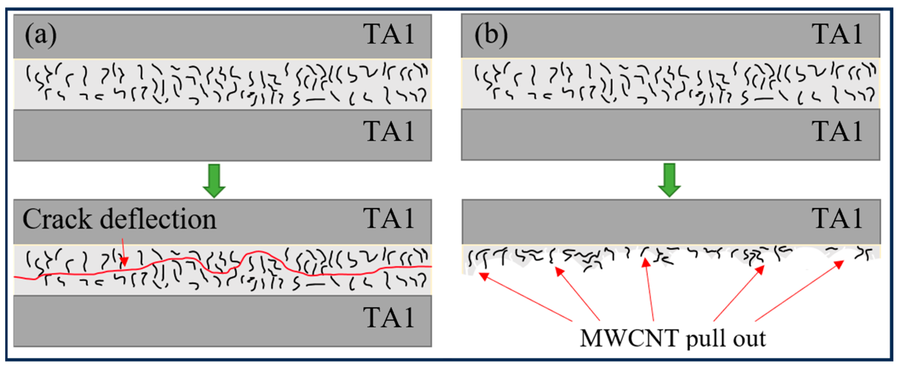
The short beam shear failure test model of the TA1/CFRP laminates is illustrated in Figure 9, consisting of three main parts: a TA1 microscale laminate, a metal–resin matrix binding laminate, and a fiber-reinforced composite material comprising resin and carbon fiber. Shear failure primarily occurs in the binding layer between the TA1 metal and resin matrix. Under load, shear stress is generated by the bending of the laminate, leading to the initiation of small cracks in the bonding layer. As stress increases, these cracks gradually propagate, eventually resulting in shear failure as the punch feeds through. Figure 9a demonstrates that the addition of MWCNT to the laminate inhibits crack propagation. The distribution of MWCNT varies in different regions after resin heating and curing, with cracks preferentially propagating along regions with weaker properties. This indicates that the addition of nanotubes alters the crack propagation path and enhances the shearing performance of the laminate. Moreover, as depicted by the red arrow in Figure 9b, when the bonding layer fails, a portion of the resin matrix comes into contact with the metal surface. This contact area, occurring during MWCNT extraction, dissipates some of the energy generated by the load while improving the shearing performance of the laminate. In summary, the addition of MWCNT changes the mode of shear failure expansion and enhances shear strength. This enhancement is evident in two aspects: Firstly, MWCNT deflects shear damage and prevents rapid expansion of the bonding layer, thereby improving interfacial performance. Secondly, MWCNT increases the energy required for crack extension through its mechanical properties, such as tensile strength, fracture toughness, and bridging, consequently enhancing shear strength.
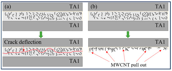
Figure 9.
Influence mechanism of MWCNT in interlaminar shear test, (a) crack deflection, and (b) fiber pull out.
4.2. Effect of MWCNT Content on Fracture Toughness
Table 5, Table 6, Table 7 and Table 8 present the displacement and load observations of specimens with different MWCNT contents. The displacement and load values correspond to certain crack lengths and capture the changes in energy release rate during stable crack growth. In this section, the crack resistance behavior during the key stages of the stratification process is analyzed preferentially, which is consistent with the methods already established in the fracture studies of FMLs [20]. Due to the equipment limitations for high-precision crack length monitoring during dynamic failure, the statistical dispersion is omitted in Table 5, Table 6, Table 7 and Table 8, and each observation point represents a unique crack length-dependent measurement within a single specimen. It is evident that specimens with added MWCNT exhibit a trend of increased critical load at observation points compared to pure epoxy resin specimens. This indicates that higher loads are required for interlayer fracture, thus enhancing the fracture toughness of the laminates. Fracture toughness was calculated for each point using the formula, revealing a trend of increasing fracture toughness with the addition of MWCNT, followed by a decrease. This trend can be attributed to MWCNTs absorbing some of the energy during interlayer failure, thereby enhancing the interlayer fracture toughness of the laminates. However, at 1.0 wt% content, the property of the laminate decreases due to MWCNT aggregation in the resin, leading to stress concentration and facilitating crack propagation, thereby reducing fracture toughness. Despite the drawbacks at 1.0 wt% content, the average fracture toughness remains higher than that of pure epoxy resin laminates, indicating that dispersed MWCNTs in the resin matrix still contribute to reinforcement.
Table 5.
Critical displacement and load of key points with MWCNT content of 0.0 wt%.
Table 6.
Critical displacement and load of key points with MWCNT content of 0.5 wt%.
Table 7.
Critical displacement and load of key points with MWCNT content of 0.75 wt%.
Table 8.
Critical displacement and load of key points with MWCNT content of 1.0 wt%.
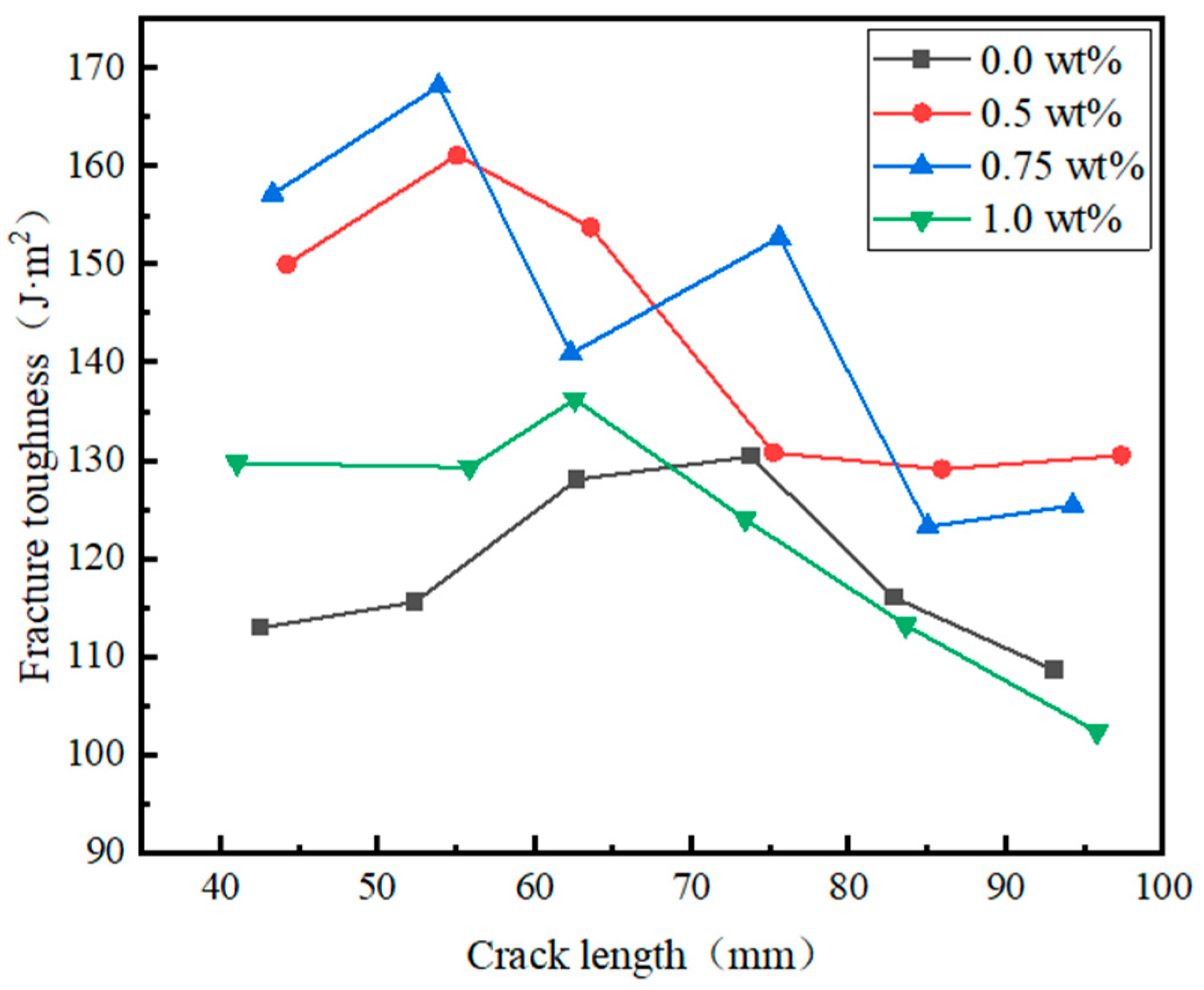
The fracture toughness–displacement curves of type I fractures at six observation points of the laminate are depicted in Figure 10, alongside the calculation of the average type I fracture toughness value for each specimen. It is noticeable that the curves for specimens containing 0.5 wt% and 0.75 wt% MWCNT surpass those of the pure epoxy resin, displaying relatively smooth profiles except for the 0.75 wt% curve, which exhibits significant fluctuations likely due to defects at the third observation point. Additionally, the curves are not parallel to the x-axis due to differing curing conditions of resin and MWCNT in different regions of the same sample. From Table 9, it is evident that the fracture toughness reaches its maximum value at 0.75 wt% MWCNT content, with an average fracture toughness of 144.6 J/m2, representing a 22% increase compared to pure epoxy resin laminates. This enhancement is attributed to MWCNTs absorbing energy in the resin through tensile and fracture mechanisms, thus enhancing the specimen’s fracture toughness. However, at 1.0 wt% MWCNT content, the fracture toughness of carbon fiber/titanium alloy laminates decreases due to MWCNT agglomeration, which adversely affects the adhesion between the metal and resin layers, consequently reducing the load required to initiate metal layer separation in type I fracture toughness tests. The average values are used in Table 9 to summarize the overall performance of crack propagation phases, which effectively integrate the nonlinear energy dissipation during complex crack propagation [26]. As a macro-performance indicator, the average values directly show the effect of MWCNT content on interlaminar fracture toughness. Furthermore, Konstantakopoulou et al. [23] found that when the content of MWCNT in the epoxy adhesive was 0.5–0.75 wt%, the interfacial strength was the best. Khurram et al. [24] pointed out that when the content of nanoparticles exceeded 0.8 wt% in CFRP/Al FMLs, the shear strength decreased due to the aggregation of nanoparticles. The consistency of the experimental data with these research results highlights the reliability of the conclusions.
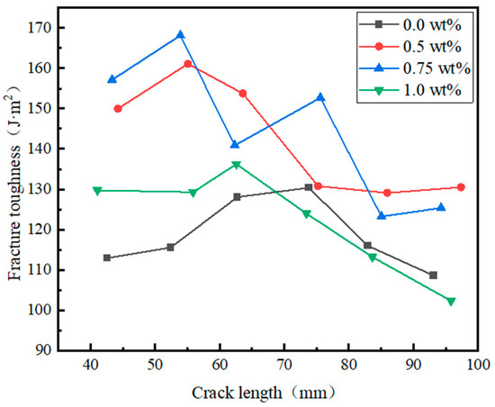
Figure 10.
Fracture toughness crack length curve of specimens with different MWCNT content.
Table 9.
Maximum, minimum and average fracture toughness values of laminates with different MWCNT contents.
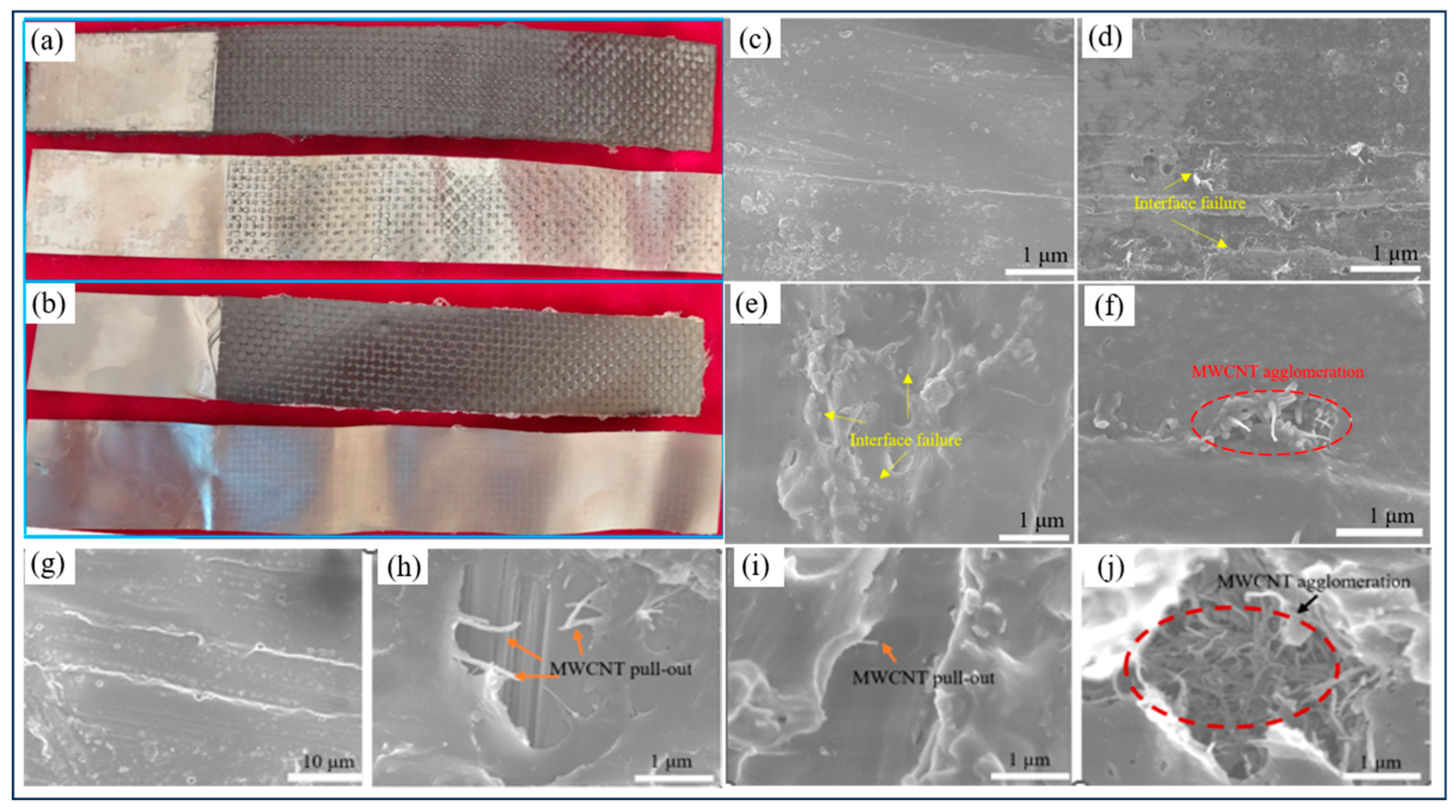
As depicted in Figure 11, the surface morphology after interlayer fracture of pure epoxy resin laminates (Figure 11a) and laminates containing 0.5 wt% MWCNT (Figure 11b) reveals notable differences. In the case of pure epoxy resin laminates, the resin attached to the surface is significantly lower compared to laminates containing MWCNT. Conversely, a substantial amount of resin residue is observed on the surface of the latter. This observation suggests that laminates with MWCNT experience more cohesion damage after fracture. This is attributed to the appropriate content of MWCNT enhancing the performance of the interface layer between TA1 and the resin matrix. The propagation of cracks is mitigated by MWCNT through the application of pull-out and fracture mechanisms, thereby requiring more energy for interlayer damage to occur. According to the stress transfer theory [28], MWCNTs actively take up load from the epoxy matrix via the shear-lag mechanism during elastic deformation. As loading increases and microcracks develop, they help dissipate energy through shear-sliding during plastic deformation. At high loads approaching fracture, MWCNTs resist crack propagation through pull-out, providing an additional toughening mechanism.

Figure 11.
Morphological analysis images of interlayer fracture toughness test, (a) surface morphology of test pieces with different MWCNT contents 0.0wt%, and (b) 0.5 wt%, (c–f) SEM scanning electron microscope image of interlayer failure at MWCNT contents of (c) 0.0 wt%, (d) 0.5 wt%, (e) 0.75 wt% and (f) 1.0 wt%, and (g–j) SEM scanning electron microscope image of influence mode of MWCNT at MWCNT contents of (g) 0.0 wt%, (h) 0.5wt%, (i) 0.75 wt%, and (g) 1.0 wt%.
The addition of MWCNT alters the failure mode of the interfacial layer between TA1 and the resin matrix, as illustrated in Figure 11c–f. In Figure 11c, the surface of the interfacial layer in the pure epoxy resin specimen appears relatively smooth post-test. However, noticeable long grooves were observed on the resin surface, indicating that after being sanded with sandpaper, the metal was more tightly bonded with the resin, forming a better mechanical interlock. During the interlayer fracture toughness test, this part of the resin was fractured along with the resin matrix as the metal layer was peeled away. In contrast, Figure 11d,e depict a significant number of resin tear zones (indicated by yellow arrows) in the interfacial layer of specimens with 0.5 wt% and 1.0 wt% MWCNT. Here, MWCNT in the resin matrix leads to crack propagation from the interfacial layer to the resin matrix, necessitating higher loads to induce interfacial failure in FMLs. Consequently, the destruction surface extends along the epoxy matrix, which has a much lower fracture toughness. Moreover, Figure 11f displays a relatively smooth failure surface of the specimen with MWCNT agglomeration. This is attributed to the excessive MWCNT content agglomerating in the resin, resulting in poor interlayer bonding property and stress concentration during load loading. As a result, lower interlayer fracture toughness is observed, and the mode of crack extension transitions to bonding failure.
Microscopic observations of the test damage site reveal distinct differences based on the presence of MWCNT in the resin matrix and its effect on failure propagation at the metal-epoxy resin interface layer, as depicted in Figure 11g. In the absence of MWCNT, there are no visible exposed carbon fibers on the damaged surface of the specimen, indicating failure propagation did not occur at the metal-epoxy resin interface layer. Conversely, in Figure 11h and Figure 11i, exposed carbon fibers are evident in the resin tearing area, suggesting failure propagation from the metal-epoxy interface layer to the epoxy-carbon fiber interface layer. Moreover, the presence of MWCNT leads to pull-out and fracture observed at the resin failure site, indicating that MWCNT absorbs more energy through its own fracture and friction pull-out with the resin matrix during load transfer, alleviating stress concentration generated by crack propagation. Additionally, MWCNT plays a role in preventing crack expansion and deflection, thus improving bonding property between the TA1 and the resin matrix. This is evidenced by the large amount of resin tears and shedding during interlayer failure, where the load required for resin cohesion failure exceeds that for resin-metal bonding failure. However, as depicted in Figure 11j, when MWCNT content reaches 1.0 wt%, inadequate dispersion due to insufficient ultrasonic treatment results in defects such as bubbles within the cured laminate, interface failure between the TA1 and resin matrix, and easy cracking of the agglomerates, severely impacting laminate performance.
5. Conclusions
In this paper, carbon nanotube-reinforced ultra-thin carbon fiber/titanium alloy laminates were prepared, the interlayer properties were investigated, and the influence of MWCNT on the interlayer properties was obtained; the influence mechanism of MWCNT in the above tests was obtained through microscopic characterization. The research conclusions are as follows.
- (1)
- Ultrasonic dispersion and dispersant sharing methods were employed to achieve a well-dispersed Tai/CFRP laminates with MWCNT in the resin matrix. Through carefully controlling the temperature profile and vacuum pressure during the curing process, laminates with minimized glue overflow were successfully prepared. These controlled parameters ensure uniform distribution of MWCNT within the resin matrix and reduce the overflow during curing, ultimately contributing to the overall quality and performance of the laminates.
- (2)
- The shear strength of specimens with added MWCNT exhibited an increase at concentrations of 0.5 wt%, 0.75 wt%, and 1.0 wt% compared to pure epoxy laminates. However, this increase followed a trend of initially rising and then decreasing. A significant observation was the alteration of the failure mode from bonding failure to cohesion failure with the addition of MWCNT. This change in failure mode suggests that MWCNT incorporation influenced the interfacial bonding within the laminates, leading to enhanced cohesion between the layers.
- (3)
- The type I fracture toughness of the laminates was assessed using the double-arm suspension beam method across various MWCNT contents. The incorporation of MWCNT led to a notable enhancement in the type I fracture toughness of the laminates compared to pure epoxy resin laminates. Upon analysis of the interlayer morphology and mechanism of MWCNT enhancement, it was observed that MWCNT played a crucial role through mechanisms such as pull-out and fractures, effectively impeding the pre-constrained expansion of cracks within the matrix. This mechanism ultimately contributed to the improvement in interlayer fracture toughness of the laminates.
- (4)
- This study successfully revealed the reinforcing effect of MWCNTs on the mechanical properties of composites. However, there are certain limitations. On the one hand, the key range for optimal performance may not have been fully captured due to the selected MWCNT content range. On the other hand, the study only focused on the mechanical behavior at room temperature, lacking adequate evaluation of material performance in complex service environments like high temperatures. Future research should systematically expand the range of MWCNT content and include performance tests under different temperature conditions.
Author Contributions
Conceptualization, Q.Z. and Y.W.; methodology, Q.Z.; software, Z.Z.; validation, Q.Z., J.C. and Y.W.; formal analysis, Z.Z.; investigation, Z.S.; resources, Q.Z.; data curation, Z.S.; writing—original draft preparation, Q.Z.; writing—review and editing, Y.W.; visualization, J.C.; supervision, Q.Z.; project administration, Y.W.; funding acquisition, Q.Z. All authors have read and agreed to the published version of the manuscript.
Funding
This research was funded by National Science and Technology Major Special Projects (2024ZD0703101), the National Key Research and Development Program of China (2023YFB2504604), the National Natural Science Fund of China (52005153), the Tianjin “Project + Team” Key Training Program (XC202052), the Local Science and Technology Development Fund Projects Guided by the Central Government of China (206Z1803G), the Key Program of Research and Development of Hebei Province (23311812D), and the Natural Science Foundation of Hebei Province (E2023202183).
Data Availability Statement
The original contributions presented in this study are included in the article. Further inquiries can be directed to the corresponding author.
Conflicts of Interest
Author Zhang Quanda was employed by the company Beijing National Innovation Institute of Lightweight Ltd. The remaining authors declare that the research was conducted in the absence of any commercial or financial relationships that could be construed as a potential conflict of interest.
References
- Matthews, F.L. Glare: History of the development of a new aircraft material. Aeronaut. J. 2002, 106, 1–20. [Google Scholar]
- Tisza, M.; Czinege, I. Comparative study of the application of steels and aluminium in lightweight production of automotive parts–sciencedirect. Int. J. Lightweight Mater. Manuf. 2018, 1, 229–238. [Google Scholar]
- Matthews, F.L.; Rawlings, R.D. Composite materials: Engineering and science. Mater. Des. 1995, 16, 119–120. [Google Scholar]
- Jin, K.; Wang, H.; Tao, J.; Du, D. Mechanical analysis and progressive failure prediction for fibre metal laminates using a 3D constitutive model. Compos. Part A Appl. Sci. Manuf. 2019, 124, 105490. [Google Scholar] [CrossRef]
- Mamalis, D.; Obande, W.; Koutsos, V.; Blackford, J.R.; Br’adaigh, C.M. Novel thermoplastic fibre-metal laminates manufactured by vacuum resin infusion: The effect of surface treatments on interfacial bonding. Mater. Des. 2019, 162, 331–344. [Google Scholar] [CrossRef]
- Hu, Y.; Zheng, X.; Wang, D.; Zhang, Z.; Xie, Y.; Yao, Z. Application of laser peen forming to bend fibre metal laminates by high dynamic loading. J. Mater. Process. Technol. 2015, 226, 32–39. [Google Scholar] [CrossRef]
- He, P.; Huang, M.; Fisher, S.; Yue, C.Y.; Yang, J. Effects of primer and annealing treatments on the shear strength between anodized Ti6Al4V and epoxy. Int. J. Adhes. Adhes. 2015, 57, 49–56. [Google Scholar] [CrossRef]
- Khalid, M.Y.; Imran, R.; Arif, Z.U.; Akram, N.; Arshad, H.; Al Rashid, A.; Márquez, F.P.G. Developments in chemical treatments, manufacturing techniques and potential applications of natural-fibers-based biodegradable composites. Coatings 2021, 11, 293. [Google Scholar] [CrossRef]
- Ye, J.; Wang, H.; Dong, J.; Liu, C.; Gao, Y.; Gong, B.; Su, B.; Peng, H.-X. Metal surface nanopatterning for enhanced interfacial adhesion in fiber metal laminates. Compos. Sci. Technol. 2021, 205, 108651. [Google Scholar] [CrossRef]
- Rubio-González, C.; Chávez, F.; José-Trujillo, E.; Rodríguez-González, J.A.; Ruiz, A. Impact behavior of carbon fiber/epoxy composites and fiber metal laminates with open holes. Fibers Polym. 2021, 22, 772–785. [Google Scholar] [CrossRef]
- Harfoush, A.; Haapala, K.R.; Tabei, A. Application of artificial intelligence in incremental sheet metal forming: A review. Procedia Manuf. 2021, 53, 606–617. [Google Scholar] [CrossRef]
- Hu, C.; Sang, L.; Jiang, K.; Xing, J.; Hou, W. Experimental and numerical characterization of flexural properties and failure behavior of CFRP/Al laminates. Compos. Struct. 2022, 281, 115036. [Google Scholar] [CrossRef]
- Jamali, N.; Khosravi, H.; Rezvani, A.; Tohidlou, E. Mechanical properties of multiscale graphene oxide/basalt fiber/epoxy composites. Fibers Polym. 2019, 20, 138–146. [Google Scholar] [CrossRef]
- Afrouzian, A.; Movahhedi Aleni, H.; Liaghat, G.; Ahmadi, H. Effect of nano-particles on the tensile, flexural and perforation properties of the glass/epoxy composites. J. Reinf. Plast. Compos. 2017, 36, 900–916. [Google Scholar] [CrossRef]
- Feiz, A.; Khosravi, H. Multiscale composites based on a nanoclay-enhanced matrix and E-glass chopped strand mat. J. Reinf. Plast. Compos. 2019, 38, 591–600. [Google Scholar] [CrossRef]
- Ebrahimnezhad-Khaljiri, H.; Eslami-Farsani, R.; Khosravi, H.; Shahrabi-Farahani, A. Improving the flexural properties of E-glass fibers/epoxy isogrid stiffened composites through addition of 3-glycidoxypropyltrimethoxysilane functionalized nanoclay. Silicon 2020, 12, 2515–2523. [Google Scholar] [CrossRef]
- Ebrahimnezhad, K.H.; Eslami, F.R. Thermal and mechanical properties of hybrid carbon/oxidized polyacrylonitrile fibers-epoxy composites. Polym. Compos. 2017, 38, 1412–1417. [Google Scholar] [CrossRef]
- Moniruzzaman, M.; Winey, K.I. Polymer nanocomposites containing carbon nanotubes. Macromolecules 2006, 39, 5194–5205. [Google Scholar] [CrossRef]
- Dyke, C.A.; Tour, J.M. Covalent functionalization of single-walled carbon nanotubes for materials applications. J. Phys. Chem. A 2004, 108, 11151–11159. [Google Scholar] [CrossRef]
- Sánchez, M.; Campo, M.; Jiménez-Suárez, A.; Ureña, A. Effect of the carbon nanotube functionalization on flexural properties of multiscale carbon fiber/epoxy composites manufactured by VARIM. Compos. Part B Eng. 2013, 45, 1613–1619. [Google Scholar] [CrossRef]
- Cividanes, L.S.; Simonetti, E.A.N.; Moraes, M.B.; Fernandes, F.W.; Thim, G.P. Influence of carbon nanotubes on epoxy resin cure reaction using different techniques: A comprehensive review. Polym. Eng. Sci. 2014, 54, 2461–2469. [Google Scholar] [CrossRef]
- de Souza, C.F.; Leite, J.L.; Salmoria, G.V.; Pouzada, A.S. Influence of graphite and carbon nanotubes on the mechanical and electrical properties of cast epoxy composites. Mater. Sci. Forum 2013, 730, 909–914. [Google Scholar] [CrossRef]
- Konstantakopoulou, M.; Kotsikos, G. Effect of MWCNT filled epoxy adhesives on the quality of adhesively bonded joints. Plast. Rubber Compos. 2016, 45, 166–172. [Google Scholar] [CrossRef]
- Khurram, A.A.; Hussain, R.; Afzal, H.; Akram, A.; Subhanni, T. Carbon nanotubes for enhanced interface of fiber metal laminate. Int. J. Adhes. Adhes. 2018, 86, 29–34. [Google Scholar] [CrossRef]
- Khoramishad, H.; Alikhani, H.; Dariushi, S. An experimental study on the effect of adding multi-walled carbon nanotubes on high-velocity impact behavior of fiber metal laminates. Compos. Struct. 2018, 201, 561–569. [Google Scholar] [CrossRef]
- Aghamohammadi, H.; Eslami-Farsani, R.; Tcharkhtchi, A. The effect of multi-walled carbon nanotubes on the mechanical behavior of basalt fibers metal laminates: An experimental study. Int. J. Adhes. Adhes. 2020, 98, 102538. [Google Scholar] [CrossRef]
- Yu, S.Z.; Min, N.T.; Gary, C. Use of carbon nanotubes reinforced epoxy as adhesives to join aluminum plates. Mater. Des. 2010, 31, 126–129. [Google Scholar] [CrossRef]
- Goh, K.L. Discontinuous-Fibre Reinforced Composites: Fundamentals of Stress Transfer and Fracture Mechanics; Springer: London, UK, 2017. [Google Scholar]

Disclaimer/Publisher’s Note: The statements, opinions and data contained in all publications are solely those of the individual author(s) and contributor(s) and not of MDPI and/or the editor(s). MDPI and/or the editor(s) disclaim responsibility for any injury to people or property resulting from any ideas, methods, instructions or products referred to in the content. |
© 2025 by the authors. Licensee MDPI, Basel, Switzerland. This article is an open access article distributed under the terms and conditions of the Creative Commons Attribution (CC BY) license (https://creativecommons.org/licenses/by/4.0/).