Article

Molecular Dynamics Simulation of the Effect of B2-NiAl Phase Volume Fractions on Mechanical Properties and Deformation Mechanisms of Dual-Phase FeNiAl Alloys

1
No. 1 Steel Making and Rolling Plant, Hunan Valin Lianyuan Iron and Steel Co., Ltd., Loudi 417009, China
2
State Key Laboratory of Advanced Processing and Recycling of Non-Ferrous Metals, School of Materials Science and Engineering, Lanzhou University of Technology, Lanzhou 730050, China
*
Authors to whom correspondence should be addressed.
The authors contributed equally to this work.
Metals 2025, 15(7), 738; https://doi.org/10.3390/met15070738
Submission received: 6 May 2025 / Revised: 19 June 2025 / Accepted: 27 June 2025 / Published: 30 June 2025

Abstract

In this study, the effects of B2-NiAl phase volume fractions (2–50%) on the mechanical properties and deformation mechanism of dual-phase FeNiAl alloys were systematically investigated by molecular dynamics simulation. A two-phase alloy atomic model with different B2 phase volume fractions was constructed. The simulation results show that when the volume fraction of the B2 phase is 3%, the alloy exhibits the best comprehensive mechanical properties. The strengthening is mainly due to the back stress field effect induced by the B2 phase. However, when the content of the B2 phase exceeds 5%, it will cause grain boundary stress concentration, resulting in a sharp decrease in the ductility of the alloy. Atomic-scale simulation analysis further reveals that low B2 content (3%) maintains grain boundary stability by inhibiting grain rotation, regulating superdislocation pairs and inverse boundary slip modes. This study provides a theoretical basis for the design of dual-phase alloys, reveals the cooperation mechanism of B2 and FCC, and has guiding significance for the development of high-strength and toughness Fe-based alloys.

1. Introduction

The FeNiAl alloy system is a ternary alloy with Fe as the matrix, incorporating Ni and Al as key alloying elements. The addition of Ni plays a critical role in enhancing the alloy’s corrosion resistance and high-temperature stability [1]. Under elevated temperatures, Ni facilitates the formation of a dense oxide layer on the alloy surface, which effectively inhibits further interaction between oxygen (or other corrosive media) and the alloy matrix, thereby improving its resistance to high-temperature corrosion [2,3,4]. Concurrently, the incorporation of Al not only reduces the alloy’s density but also significantly strengthens the material through the formation of an ordered B2-NiAl phase [5,6,7]. Traditional single-phase Fe-based alloys face intrinsic limitations due to their crystal structure-dependent deformation mechanisms. For instance, face-centered cubic (FCC) structures (e.g., γ-Fe) exhibit excellent plasticity via mechanisms such as full dislocation glide and twinning, yet their yield strength remains inherently low. In contrast, body-centered cubic (BCC) ordered intermetallic compounds (e.g., B2-NiAl phase) possess high strength but suffer from restricted slip systems and elevated antiphase boundary (APB) energy, which impedes dislocation motion and induces low-temperature brittleness [8,9,10]. This inherent “strength-ductility trade-off” dilemma severely constrains the engineering application of high-performance Fe-based alloys.
To overcome this limitation, researchers have proposed constructing dual-phase or multiphase heterogeneous structures to achieve synergistic enhancement of strength and ductility through coordinated deformation mechanisms between different phases. For example, Wu et al. [11] introduced secondary phases in Mg-Y-Ni alloys and found that adjusting the phase ratio could optimize deformation uniformity and work-hardening capability. Ye et al. [12] achieved a breakthrough in Al0.25FeCoNiV high-entropy alloys by constructing an L12/B2 fine-grained dual-phase microstructure, realizing a remarkable combination of ultimate tensile strength (1530 MPa) and ductility (20%). Niu et al. [13] employed nanoscale co-precipitation (FCC-L12 and B2-α′/Laves phases) and hierarchical heterostructure design to simultaneously enhance room-temperature and high-temperature strength in eutectic high-entropy alloys, resolving the “high-temperature strength-plasticity mismatch” while maintaining 10–50% ductility. However, current research on dual-phase alloys faces the following unresolved issues: Although experiments have confirmed the decisive regulatory role of hard-phase volume fractions on mechanical properties, existing studies primarily focus on phase-type selection and interface characteristic optimization [6,14], while systematic exploration of the quantitative influence of hard-phase content remains lacking. Particularly at the atomic scale, the correlation mechanisms between hard-phase content and dislocation evolution, grain boundary (GB) migration, and phase transformation behavior remain unclear, and a universal model linking hard-phase content to material performance is still absent. Additionally, the performance optimization of dual-phase alloys inherently relies on multi-scale synergy, yet experimental models based on continuum medium assumptions struggle to reveal the contribution of atomic-scale dynamic processes to macroscopic responses. The absence of cross-scale correlation mechanisms prevents traditional empirical design methods from accurately predicting the nonlinear effects of hard-phase volume fractions. Solving these issues is crucial for the rational design of dual-phase alloys and represents a core challenge in current materials research.
To address the aforementioned challenges, this study employs FeNiAl dual-phase alloys as a model system to systematically investigate the influence of B2-NiAl phase volume fractions (2–50%) on mechanical properties and deformation mechanisms using molecular dynamics (MD) simulations [15]. Molecular dynamics (MD) simulation has unique advantages in revealing the microscopic mechanism of atomic scale during material deformation. MD can capture key dynamic processes such as dislocation evolution (such as superdislocation pair decomposition, Lomer–Cottrell lock formation), grain boundary migration, and phase boundary response (such as back stress field generation, inverse phase boundary slip) in real time and clearly, which is crucial for understanding the microscopic origin of the performance differences of FeNiAl dual-phase alloys with different B2 phase contents (2–50%). However, the traditional MD simulation is limited by its time scale (nanoseconds to microseconds) and sample size (usually nanoscale), and it may be difficult to directly simulate the long-term behavior of macroscopic materials or complex structures containing a large number of grains. In order to partially overcome these limitations and enhance the structural complexity and representativeness of the model, this study constructed a polycrystalline Voronoi model. The model is closer to the microstructure characteristics of real polycrystalline materials by introducing multiple randomly oriented grains and complex grain boundary/phase boundary networks, thus improving the reliability of simulation results and the ability to predict the deformation behavior of actual alloys. The selection of the FeNiAl system is grounded in the following rationale: (1) The FCC-Fe phase provides sufficient plastic deformation capacity, while the B2-NiAl phase enhances strength via its ordered lattice structure and high APB energy [16]; (2) the lattice constant mismatch (FCC: 0.356 nm, B2: 0.289 nm) and elastic modulus disparity between the two phases induce heterogeneous deformation-induced (HDI) effects [17,18,19].
Building upon prior research [20], compositional optimization of the FeNiAl alloy is implemented to strengthen the FCC-Fe matrix. By systematically varying the B2 phase volume fraction, this work elucidates the correlation between B2 phase content and the strength-ductility synergy in dual-phase FeNiAl alloys. A critical mechanism is identified: Low B2-phase content optimizes back stress fields through HDI hardening, whereas high B2-phase content triggers brittle failure due to interfacial stress concentration and limited dislocation mobility. These findings establish a theoretical foundation for the composition design and performance optimization of dual-phase alloys, thereby advancing the targeted development of high-strength, high-toughness Fe-based alloys for extreme-environment engineering applications.

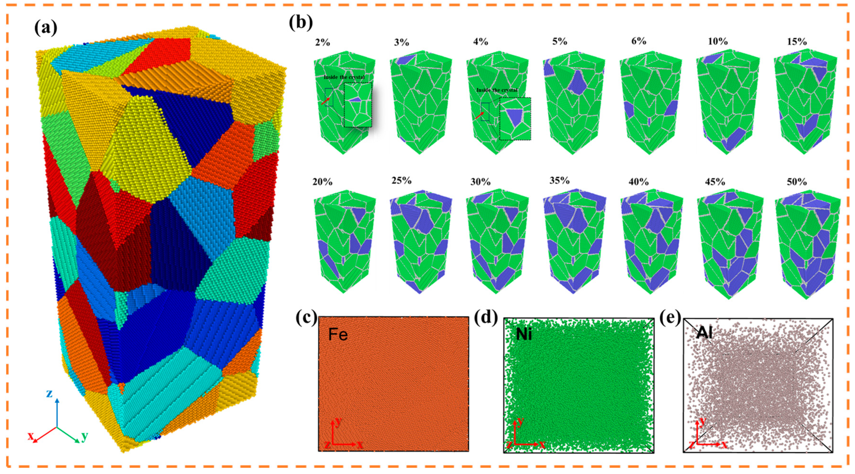
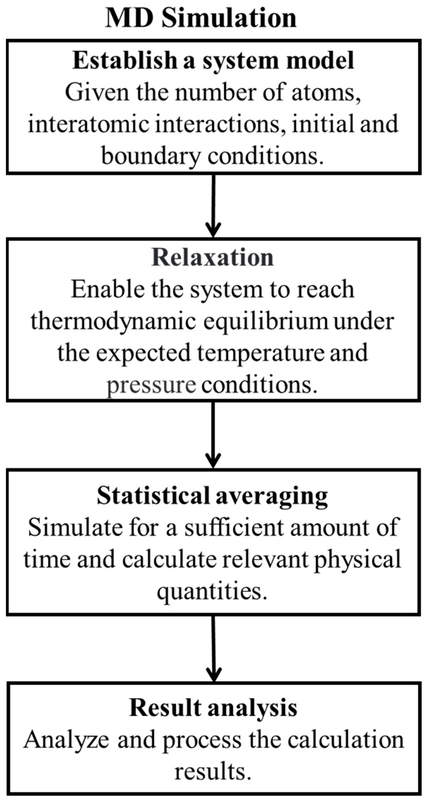
2. Simulation Methods

MD simulations serve as a bridge between experimental and theoretical approaches, providing robust validation for experimental findings and enabling computational verification. This study employs the classical MD simulation software LAMMPS 3 Mar 2020 [21] for calculations, with structural and dislocation analyses conducted using the Common Neighbor Analysis (CNA) [22] and Dislocation Extraction Algorithm (DXA) [23] modules in the visualization software OVITO [24]. The interatomic interactions for the FeNiAl alloy system are described by the embedded atom method (EAM) potential, which has been rigorously validated by Diana Farkas et al. [25]. The modeling procedure is summarized in Figure 1.
To investigate the influence of B2-NiAl phase volume fractions on the mechanical properties and deformation behavior of dual-phase FeNiAl alloys, polycrystalline models were established using the Voronoi tessellation method via Atomsk [26]. As shown in Figure 1a, the model dimensions are 20 × 18 × 45 nm3, containing 22 grains and 1,332,715 atoms. The lattice constants of the FCC phase and B2 phase are 0.356 nm and 0.289 nm, respectively. Figure 1b displays alloy models with B2 volume fractions ranging from 2% to 50% (incremented as 2%, 3%, 4%, 5%, 6%, 10%, 15%, 20%, 25%, 30%, 35%, 40%, 45%, and 50%), where green atoms represent the FCC-Fe90Ni9Al structure, which exhibits the best mechanical properties [27], blue atoms denote the B2-NiAl phase, and white atoms indicate grain boundaries. Figure 1c–e presents the z-axis projection maps of Fe, Ni, and Al elemental distributions, revealing no significant elemental segregation in the FeNiAl alloy system, which suggests uniform dispersion of distinct atomic species. Periodic boundary conditions were applied in all directions. After relaxation optimization at an initial temperature of 300 K, the stabilized structural models were subjected to uniaxial tensile deformation along the z-axis at a strain rate of 1 × 10⁹ s−1 under the NPT ensemble. “NPT ensemble represents a thermodynamic ensemble in which the Number of particles (N), Pressure (P), and Temperature (T) are kept constant during the simulation. This ensemble allows the simulation cell to adjust its volume to maintain constant pressure, enabling more realistic modeling of material deformation under external loading.” Figure 2 shows the flow chart of the whole simulation process, from the initial model generation to the optimization of atomic structure, the application of boundary conditions, the loading process, data acquisition and analysis, and other key steps. Mechanical properties analysis was subsequently performed based on the computational results.

3. Results and Discussion

3.1. Mechanical Properties

The engineering stress–strain curves reveal the variations in yield strength and tensile strength of the material with respect to the B2 phase volume fraction. Yield strength corresponds to the stress at which plastic deformation initiates under applied load. Tensile strength, defined as the maximum stress a material can withstand before necking during static tensile loading, represents the transition from uniform to localized plastic deformation. Analysis of these curves demonstrates that an optimal B2-NiAl phase volume fraction enhances material strength. As shown in Figure 3a,b, dual-phase alloys with a low B2 phase volume fraction (~3%) exhibit superior yield and tensile strengths, whereas higher B2 phase content leads to reduced tensile strength. The alloy with 3% B2 phase volume fraction further displays strain hardening during deformation and retains favorable plastic ductility. Figure 3c compares engineering stress–strain curves for alloys with 0%, 3%, and 5% B2 phase volume fractions, highlighting that the incorporation of the B2 phase improves both strength and plasticity. Specifically, the 3% B2 phase alloy achieves the highest tensile strength, while the 5% B2 phase alloy shows enhanced ductility compared to the B2-free Fe90Ni9Al polycrystalline material. Figure 3d confirms that the alloy with 3% B2 phase volume fraction attains peak mechanical performance, with yield and tensile strengths reaching 4.52 GPa and 4.74 GPa, respectively.

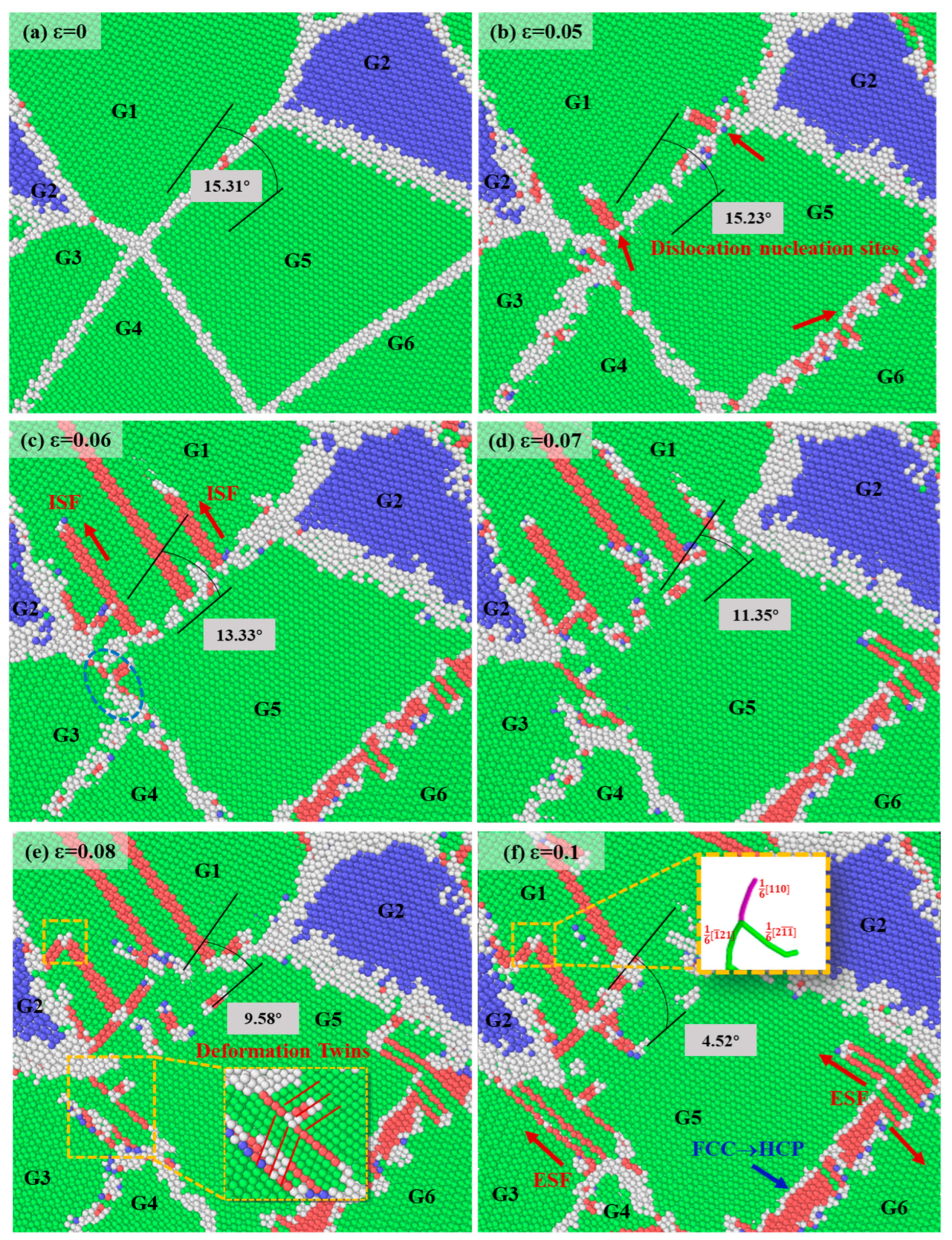
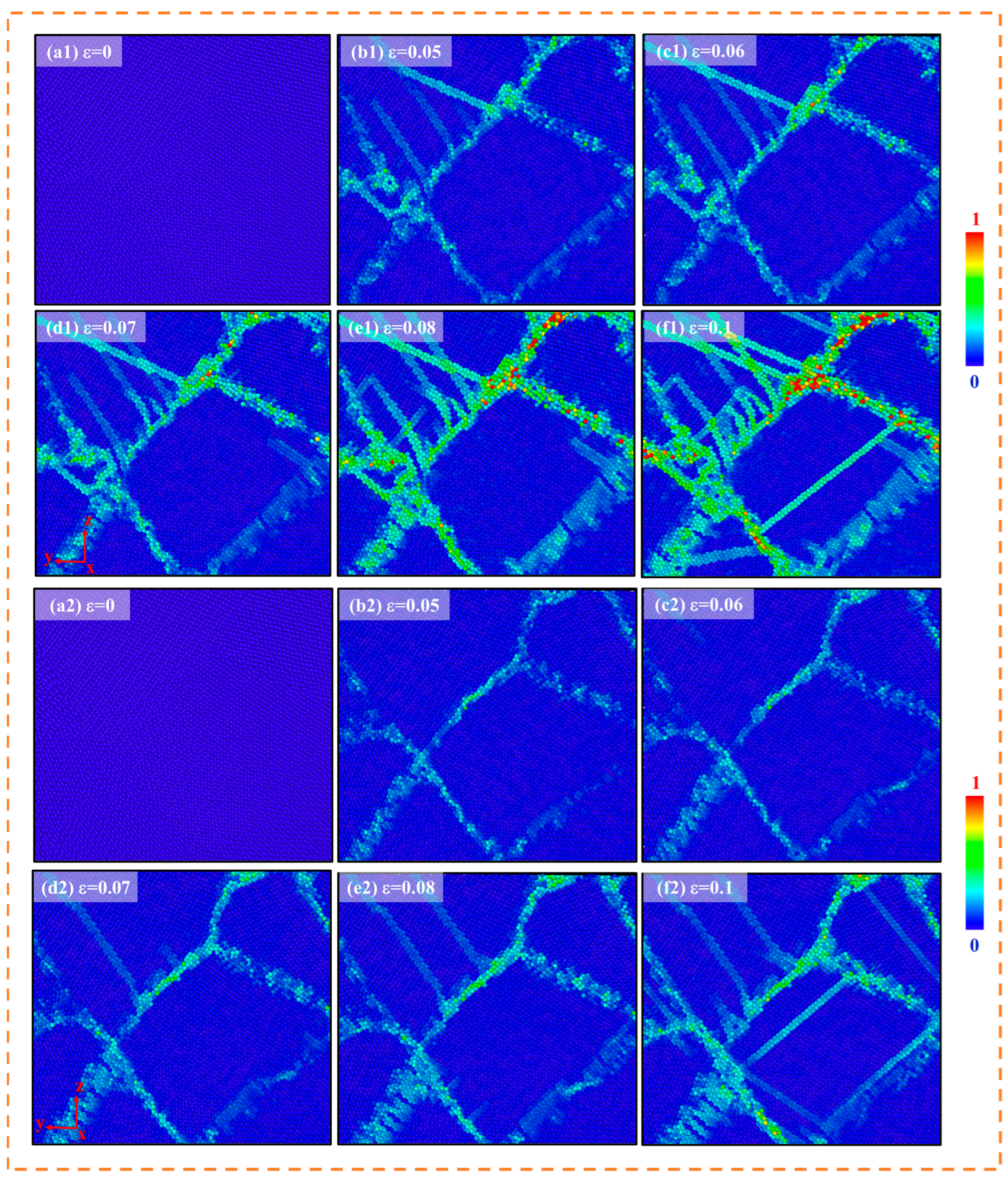
3.2. Evolution of Deformation Mechanisms

To investigate the influence of B2 phase incorporation within grains on alloy deformation mechanisms, an alloy with 5% B2 phase volume fraction was analyzed. Grains 1–6 on the Y-Z plane were numbered for clarity (Figure 4a), which also illustrates their initial positions and the original misorientation angle (15.31°) between grains G1 and G5. Notably, grain 2 was bisected due to periodic boundary conditions. As strain increased, dislocation nucleation sites emerged near grain boundaries (GBs), driven by localized stress concentration at these high-energy regions under external loading. The misorientation angle between G1 and G5 decreased from 15.31° to 4.52° as strain increased from 0% to 10%, indicating a grain rotation of 10.79° in the 5% B2 phase alloy. The red arrows in Figure 4b show the nucleation sites of the Shockley partial dislocations. Figure 4c highlights the migration of the GB between G3 and G5 (marked by blue circles). At 6–10% strain, grain 4 shifted downward, leading to the gradual disappearance of the GB between grains 3 and 5. This triggered grain coarsening through the consumption of smaller grains by larger ones, altering the equilibrium microstructure. A critical observation is the transformation of the vanishing GB into a twin boundary (Figure 4e). This phenomenon arises from the synergistic interplay of energy minimization, localized stress distribution, crystallographic anisotropy, and external loading conditions. The underlying mechanism involves structural reorganization under applied stress to optimize energy dissipation and stress redistribution. As indicated by the yellow dashed box in Figure 4f, the progressive increase in strain induces intersecting stacking faults on distinct slip planes, forming Lomer–Cottrell locks that significantly impede dislocation motion within grains. This restriction of dislocation mobility by Lomer–Cottrell locks contributes to enhanced alloy strength. Concurrently, an FCC → HCP phase transformation is observed at this strain level [27], as marked by the blue arrow in Figure 4f. The martensitic transformation occurs at the interface between G5 and G6, characterized by a low-angle grain boundary (LAGB) with a misorientation of 7.25°. The FCC → HCP transformation nucleates directly from stacking faults, predominantly at LAGBs [28]. In the FCC phase, a full 1/2<110> dislocation on the {111} plane dissociates into two 1/6<211> Shockley partial dislocations, with the intervening stacking fault region forming a two-layer HCP structure. This configuration acts as an embryonic nucleus for the HCP phase. The nucleation process involves two distinct critical stages: subcritical embryos and critical embryos, where the energy difference between these states governs the energy barrier for martensitic transformation. Furthermore, the elevated dislocation density near LAGBs facilitates HCP phase nucleation by providing localized stress concentrations and defect-driven nucleation sites.
To further explore grain rotation and GB migration phenomena observed in Figure 4, the alloy with a 3% B2 phase volume fraction was analyzed under identical strain conditions (0–10%). The misorientation angle between G1 and G5 decreased from 15.31° to 10.30°, corresponding to a reduced rotation angle of 5.01° compared to the 10.79° rotation observed in the 5% B2 phase alloy. This suppression of grain rotation at 3% B2 phase content minimizes misorientation between adjacent grains, enabling enhanced stress redistribution and structural stability, thereby significantly improving alloy strength [29]. Figure 5c illustrates the microstructure at peak tensile strength, revealing dislocation propagation along slip planes and directions. Dislocation interactions generate intrinsic stacking faults distributed across multiple grains, driving homogeneous plastic deformation and mild strain hardening. A “step-like” configuration in stacking fault motion is observed in Figure 5d (upper left), where dislocation character transitions from screw-type (upper region) to edge-type (central step) and back to screw-type (lower region). Screw dislocations, capable of gliding on any crystallographic plane containing their Burgers vector, initiate double cross-slip [30] when obstructed on their original slip plane. This process involves sequential transitions to intersecting and parallel slip planes, forming edge-type jogs (blue arrow in Figure 5d) that act as barriers to original dislocation motion. These jogs transform dislocations into multiplication sources, accelerating dislocation motion and facilitating plastic deformation. The blue circles in Figure 5d indicate the migration of the GB between G3 and G5. As strain increased from 6% to 10%, grain 4 initiated downward motion, resulting in the progressive disappearance of the GB between grains 3 and 5. This process culminated in the coalescence of grains 3 and 5, accompanied by grain coarsening through the consumption of smaller grains by larger counterparts, ultimately driving GB migration. The red arrows in Figure 5e represent the direction of motion of the partial dislocations.
In addition, dislocations in the B2 phase were observed in the alloy with a B2 phase volume fraction of 3%, as shown in Figure 5f–i. When the strain is 6%, the dislocation with a Burgers vector of 1 2 [ 1 ¯   1 ¯   1 ¯ ] appears in the B2 phase. When the strain is 10%, the existence of superdislocation pairs can be observed in the B2 phase, as shown in Figure 5i. The superdislocation pair consists of two partial dislocations separated by an APB. APBs affect the movement ability of dislocations by adjusting the equilibrium spacing between superdislocation pairs. The higher APB energy reduces the spacing between the superdislocation pairs, forcing the dislocations to ”drag” the APB during the slip process. This drag effect amplifies the slip resistance and directly leads to an increase in yield strength.
Figure 6 presents stress distribution contour maps during deformation for alloys with 5% and 3% B2 phase volume fractions. As strain increases, stress concentrations initially emerge at GBs, where most atoms deviate from their original lattice positions and are visualized as disordered atoms. Upon external stress application, comparative analysis of the two alloys reveals that the highest energy concentration occurs at the interface between grains 1 and 5. To minimize system energy, the GBs between grains 1 and 5 undergo migration, a phenomenon fully consistent with the GB motion and grain rotation processes illustrated in Figure 5. Notably, the alloy with 3% B2 phase exhibits reduced atomic stress concentrations at GBs compared to its 5% B2 phase counterpart. The introduction of 3% B2 phase effectively lowers the average GB stress, enhancing structural stability through optimized stress redistribution.
Figure 7 illustrates the microstructural evolution of the FeNiAl alloy with a 5% B2 phase volume fraction during progressive strain. Initial dislocation nucleation preferentially occurs near GBs, attributed to the inherently higher energy states at these regions. As strain increases, dislocation propagation initiates, driven by the glide of Shockley partial dislocations with Burgers vectors b = 1 6   [ 21 1 ¯ ] . This motion generates intrinsic stacking faults (ISFs) within the FCC matrix. Subsequent glide of parallel Shockley partial dislocations on adjacent slip planes induces the formation of extrinsic stacking faults (ESFs). The synergistic interaction between ISFs and ESFs governs the macroscopic plastic deformation through localized lattice shearing and strain accommodation mechanisms. Second, since grain rotation in the alloy is difficult to directly observe via angle changes in OVITO, the angular variation of grain orientations on the X-Z plane was calculated to determine whether grains underwent rotational changes. It can be seen that during strain accumulation, grains 9 and 10 rotated due to the high energy state of GB atoms induced by significant orientation differences. Under applied strain, differently oriented grains rotate to reduce misorientation angles, aiming to minimize system energy and stabilize the structure. During this process, partial energy release of GB atoms occurs, causing the misorientation angle between grains to continuously decrease with increasing strain. When the strain reaches 0.03, the GB between grains 9 and 10 starts migrating with reduced thickness. At strain 0.2, grain rotation leads to boundary separation, as indicated by the two brown arrows in Figure 7f. Rightward and leftward migrations of the GB cause the merging of grains 9 and 10, with smaller grains preferentially integrating into adjacent larger grains. This significantly enhances alloy structural stability, confirming that GB migration represents one of the primary factors influencing deformation mechanisms. Furthermore, dislocations within the B2 phase were observed in the alloy with a 5% B2 phase volume fraction, as shown in Figure 7e–h. At 9% strain, the B2 phase exhibited dislocations with Burgers vectors of 1 2 [ 11 1 ¯ ] , [010], and 1 2 [ 13 1 ¯ ] . When <111>-oriented slip systems became obstructed, the material activated <111>-type slip systems to accommodate strain energy dissipation. The 1 2 [ 13 1 ¯ ] dislocation formed via a reaction between 1 2 [ 11 1 ¯ ] and [010] dislocations, expressed as:
1 2 [ 11 1 ¯ ] + [ 010 ]     1 2 [ 13 1 ¯ ]
The coexistence of these dislocation types demonstrates the material’s ability to coordinate plasticity through multi-slip system activation, thereby adapting to complex stress states. The simultaneous operation of multiple slip systems enhances strain homogenization and substantially increases the work-hardening rate. This multi-slip mechanism provides an atomic-scale rationale for the high strength-ductility synergy in FeNiAl alloys, while elucidating the critical role of intricate dislocation interactions in strain accommodation [31,32,33].
Figure 8 illustrates phase fraction evolution in Fe90Ni9Al alloys with varying B2 phase volume fractions at different strain levels. The FCC phase content decreases progressively with increasing strain in both alloys. At 0.1 strain, a sharp rise in HCP phase volume fraction occurs, indicating the onset of stacking fault accumulation and FCC → HCP martensitic transformation. Concurrently, the “Other phases” fraction increases due to two primary mechanisms: (1) Initial “Other phases” correspond to GBs whose widening under strain elevates their volumetric contribution; (2) phase boundaries formed between HCP and FCC phases during transformation expand with progressive strain, further amplifying the “Other phases” content.
To systematically investigate dislocation dynamics during tensile deformation, dislocation length evolution was statistically analyzed under increasing strain. Figure 9a,b illustrate dislocation length evolution in the Fe90Ni9Al-FCC phase for alloys with 3% and 5% B2 phase volume fractions. With increasing strain, total dislocation density rises dominantly via Shockley partial dislocations, accompanied by minor contributions from unclassified complex dislocations. In the B2-NiAl phase (Figure 9c,d), the alloy with 3% B2 phase exhibits a single dislocation type ( b = 1 2 < 111 >), while the 5% B2 phase alloy displays multiple types, including   1 2 < 111 >, <100>, <110>, and other. High-density dislocations along <111> directions confirm preferential activation of the (110) <111> slip system, aligning with deformation mechanisms in ordered B2 structures. When the <111> slip is hindered, secondary slip systems activate through localized stress concentrations or lattice distortions, driving dislocation reactions. For instance, interactions between 1 2 [ 11 1 ¯ ] and [010] dislocations generate 1 2 [ 13 1 ¯ ] -type dislocations with complex Burgers vectors. In the 5% B2 phase alloy, increased <100>-oriented dislocation density reflects cross-slip prevalence during later deformation stages, where dislocations transition from <111> to <100> slip directions to mitigate stress localization. This slip system adaptability, governed by the low stacking fault energy of B2 phases, enhances strain compatibility and contributes to strength-ductility optimization.
The explicit presence of 1 2 < 111 >-type partial dislocations corroborate the dominance of superdislocation pairs. As shown in Figure 10, dislocations in ordered lattices glide as superdislocation pairs composed of two 1 2 < 111 > partial dislocations, separated by an APB. An APB [16] refers to a planar defect in ordered crystal structures (e.g., B2, L12) where dislocation glide induces atomic misregistry between adjacent regions. In B2-structured NiAl, Ni and Al atoms initially occupy alternating body-centered and corner positions; dislocation-mediated shear disrupts this ordering, creating APBs. APBs critically influence dislocation mobility by modulating the equilibrium spacing between superdislocation pairs. Higher APB energy reduces the spacing between superdislocation pairs, forcing dislocations to “drag” APBs during glide. This drag effect amplifies slip resistance, directly contributing to elevated yield strength. Concurrently, the energy dissipation associated with APB propagation exacerbates strain hardening. The coexistence of multiple dislocation mechanisms, superdislocation pair motion, and slip system switching collectively governs the alloy’s mechanical response: high initial yield strength (attributed to APB-mediated dislocation pinning) and pronounced work-hardening capacity (stemming from dislocation interactions) [31,32,33].
Elevated dislocation density poses potential risks due to localized stress concentrations arising from dislocation tangles, particularly near GBs or secondary phases. As shown in Figure 11, external loading triggers disordered atomic motion at marked GB regions. Large misorientation angles between grains exacerbate poor lattice matching at phase interfaces, increasing GB energy and promoting interfacial plastic deformation or fracture. Notably, no cracks were observed in the Fe90Ni9Al alloy with a 3% B2 phase volume fraction. This absence of cracking indicates enhanced stability of GB atoms in the 3% B2 phase alloy, where minimal GB atom migration into adjacent grains or intragranular regions occurs during deformation. The introduction of the 3% B2 phase effectively suppresses GB atom diffusion and stabilizes interfacial configurations, thereby mitigating strain localization and crack nucleation. These findings demonstrate that a moderate B2 phase fraction (3%) optimizes structural integrity by balancing dislocation-mediated plasticity and interfacial cohesion. The red arrows in Figure 11c, d represent the grain boundary movement direction around the crack.
Figure 12 illustrates the microstructure, stress distribution, and dislocation evolution at 5% strain to investigate interfacial contributions to deformation and strengthening in dual-phase Fe90Ni9Al alloys. Compared to single-phase Fe90Ni9Al alloys, the interface thickness between FCC and B2 phases increases significantly in dual-phase systems, enhancing interfacial strengthening by amplifying intergranular slip resistance [34]. At low B2 phase volume fractions (5% strain), B2 grains undergo purely elastic deformation. As the B2 phase fraction increases while maintaining 5% strain, partial B2 grains transition to plastic deformation, whereas FCC grains remain plastically active throughout. Dislocations within phase-transformed grains relax stress concentrations, reducing the phase transformation driving force [35,36]. Stress distribution maps in Figure 12(b1–b3) reveal compressive stress fields localized at grain and phase boundaries. Severe lattice distortions in FCC and B2 grains generate heterogeneous stress states, characterized by stress-free zones encircled by high-stress regions. These stress gradients modulate local stacking fault energy, thereby governing slip resistance and dislocation nucleation critical stress at phase/grain boundaries. The origin of interfacial strengthening or softening depends on the degree of local chemical ordering within the dual-phase Fe90Ni9Al alloy. In addition, the dual-phase Fe90Ni9Al alloy exhibits high heterogeneity in terms of chemical composition, grain structure, grain boundaries, and volume fraction of phases, which have a significant impact on the mechanical properties of the alloy [37].
Figure 13 illustrates microstructural evolution characteristics of Fe90Ni9Al alloys with 0% and 20% B2 phase volume fractions under different strains. For the alloy with a 0% B2 phase, the deformation process is dominated by homogeneous dislocation slip and minor FCC → HCP martensitic transformation. At the initial strain stage, dislocation nucleation primarily occurs at GBs with intact GB morphology. As strain increases, stacking fault density significantly rises, and adjacent grains maintain global continuity through coordinated deformation. No crack initiation or GB separation is observed, indicating that the alloy with a 0% B2 phase effectively disperses external loads via dislocation multiplication and rearrangement, exhibiting a relatively singular and controllable deformation mechanism. In contrast, the alloy with a 20% B2 phase volume fraction demonstrates markedly heterogeneous and stage-dependent deformation behavior. At low strains, the synergistic effect between the hard B2-NiAl phase and soft FCC-Fe matrix leads to uneven strain partitioning: the soft phase undergoes preferential plastic deformation, while the hard phase suppresses global yielding by bearing stresses. At this stage, the two-phase interfaces remain well-bonded without detectable defects. When the strain reaches 20%, interfacial residual stress accumulates due to intensified strain mismatch between phases, initiating micro-voids at B2/matrix interfaces. As strain further increases to 30%, pre-existing micro-voids propagate into micro-cracks with phase-selective crack paths: cracks preferentially extend along B2/matrix interfaces. This phenomenon arises from the elastic modulus mismatch between hard particles and the matrix, rendering interfaces as weak links for stress transfer. Consequently, excessive B2 phase content promotes crack initiation, while its absence (0% B2 phase) results in low strength and simplistic deformation mechanisms. The alloy with a 3% B2 phase volume fraction optimally balances high tensile strength and ductility by avoiding strain localization and interfacial cracking.
This study primarily investigates the influence of B2 phase volume fractions on the deformation behavior and mechanical properties of Fe90Ni9Al alloys, while discussing key factors affecting these aspects and proposing future research directions. In terms of mechanical properties, we compared with the research of Lu et al. [38] and found that these experimental studies also observed that the hard phase content has a regulatory effect on the yield strength and plasticity near a critical volume fraction, which is consistent with the conclusion of the B2 phase content revealed in the FeNiAl alloy. In terms of the microscopic mechanism, we also compared with Chen et al.’s research [39], and pointed out that similar grain boundary rotation, dislocation entanglement, and phase-transformation-induced plasticity showed similar trends in different material systems, indicating that the simulation method we established has strong universality and scalability. To further enhance the strength of FeNiAl alloys, introducing a third hard phase (e.g., L12 phase or precipitates) into dual-phase FeNiAl alloys proves effective. This enhancement mechanism arises from dislocations being either sheared or forming dislocation loops [40], or accumulating at phase interfaces between the matrix and third-phase particles, thereby establishing multi-level strengthening mechanisms. Consequently, adjusting the proportion of different phases will guide the design and optimization of FeNiAl alloys with tailored mechanical performance combinations.

4. Conclusions

This study systematically reveals the regulation of B2 phase volume fractions on mechanical properties and deformation mechanisms in dual-phase FeNiAl alloys through MD simulations. The conclusions are as follows:
(1)
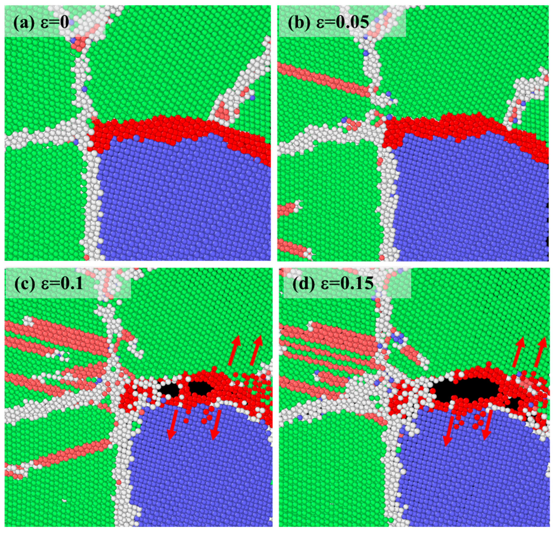
The B2 phase volume fraction nonlinearly modulates mechanical properties, with an optimal value (3%) achieving simultaneous enhancement of strength and plasticity. When the B2 phase volume fraction is 3%, the yield strength and ultimate tensile strength of the dual-phase FeNiAl alloy reach maximum values of 4.52 GPa and 4.74 GPa, representing approximately 13% and 5.3% improvements compared to the single-phase FCC-FeNiAl alloy. The material exhibits both high strength and good plasticity, primarily attributed to the B2 phase hindering dislocation motion through the back stress strengthening mechanism. However, when the B2 phase volume fraction exceeds 5%, excessive hard phases intensify stress concentration at grain boundaries, inducing micro-crack nucleation and significantly reducing ductility.
(2)
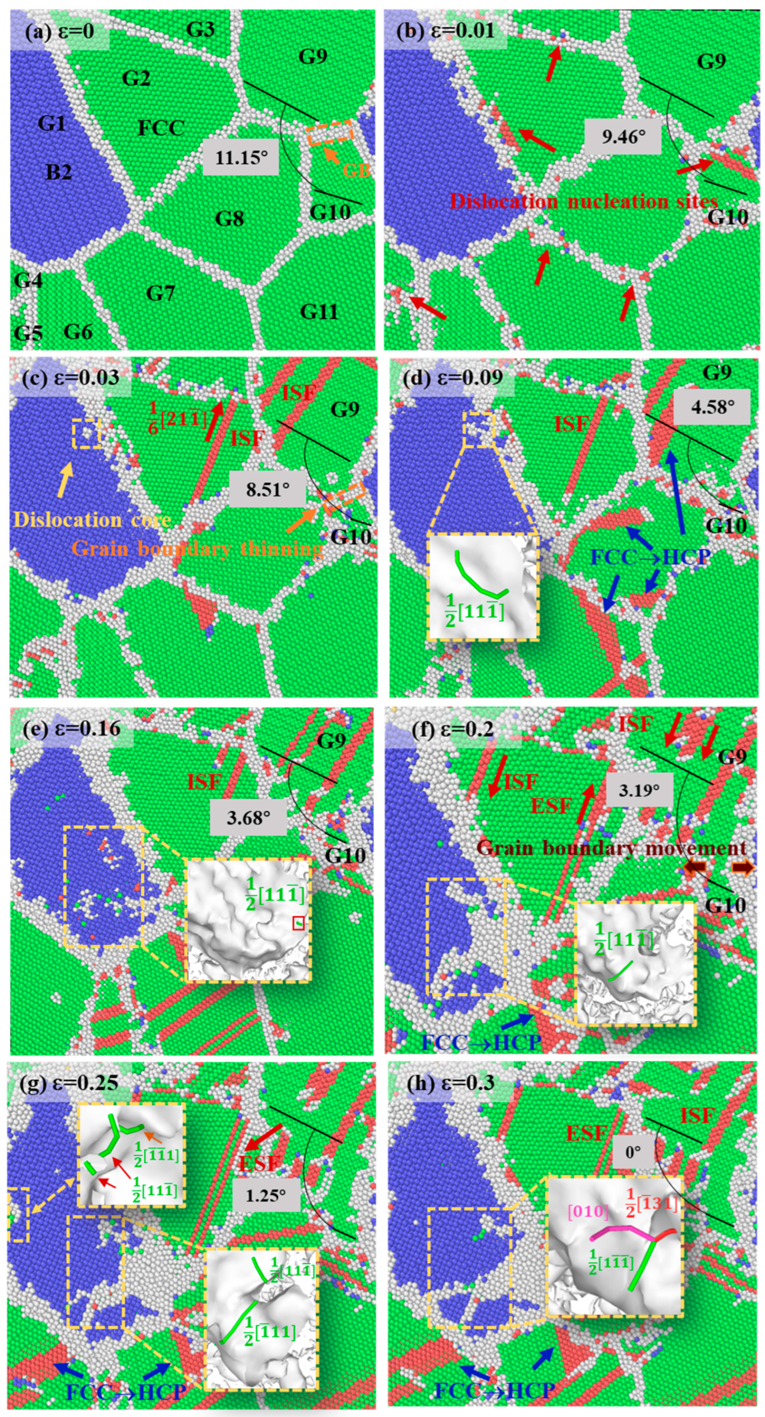
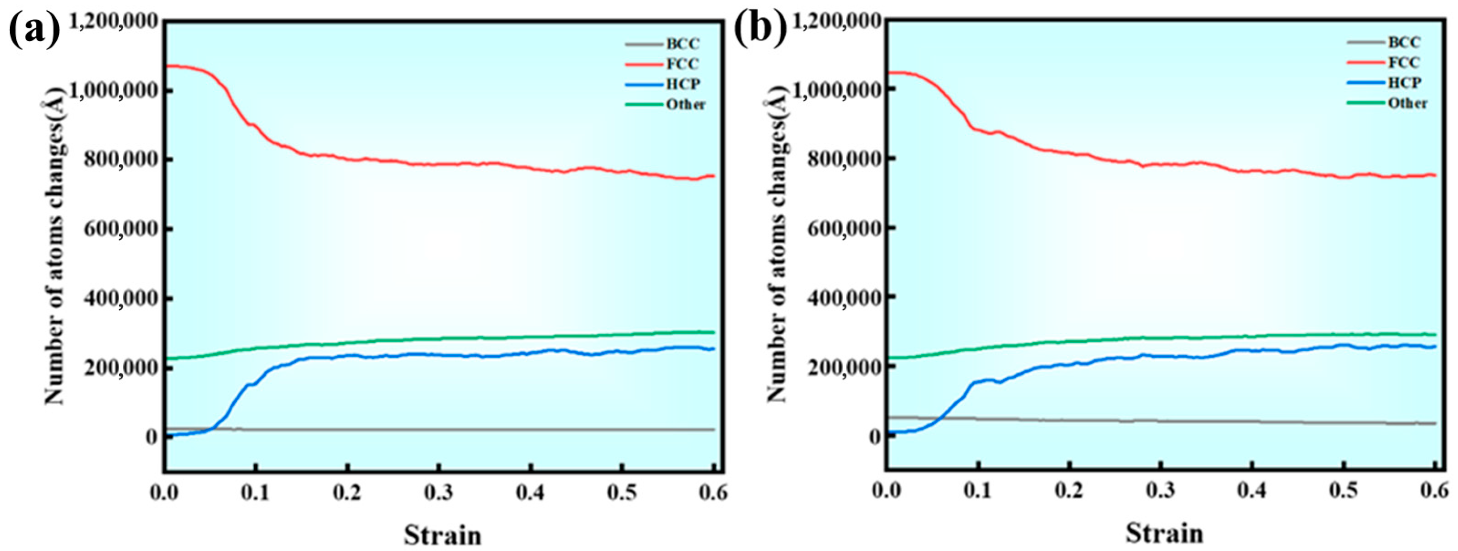
The B2 phase influences deformation mechanisms by regulating dislocation behavior and GB stability. At low B2 phase volume fractions (3%), grain rotation is suppressed (misorientation change is only 5.01°), enhancing GB stability and reducing disordered atomic diffusion. At high B2 phase volume fractions (5%), GB migration and small grain coalescence are promoted, triggering martensitic phase transformation. Additionally, dislocations generated within the B2 phase in the 3% B2 phase alloy primarily involve superdislocation pairs coupled with APB slip, while the 5% B2 phase alloy activates secondary slip systems, forming Lomer–Cottrell dislocation locks.
(3)
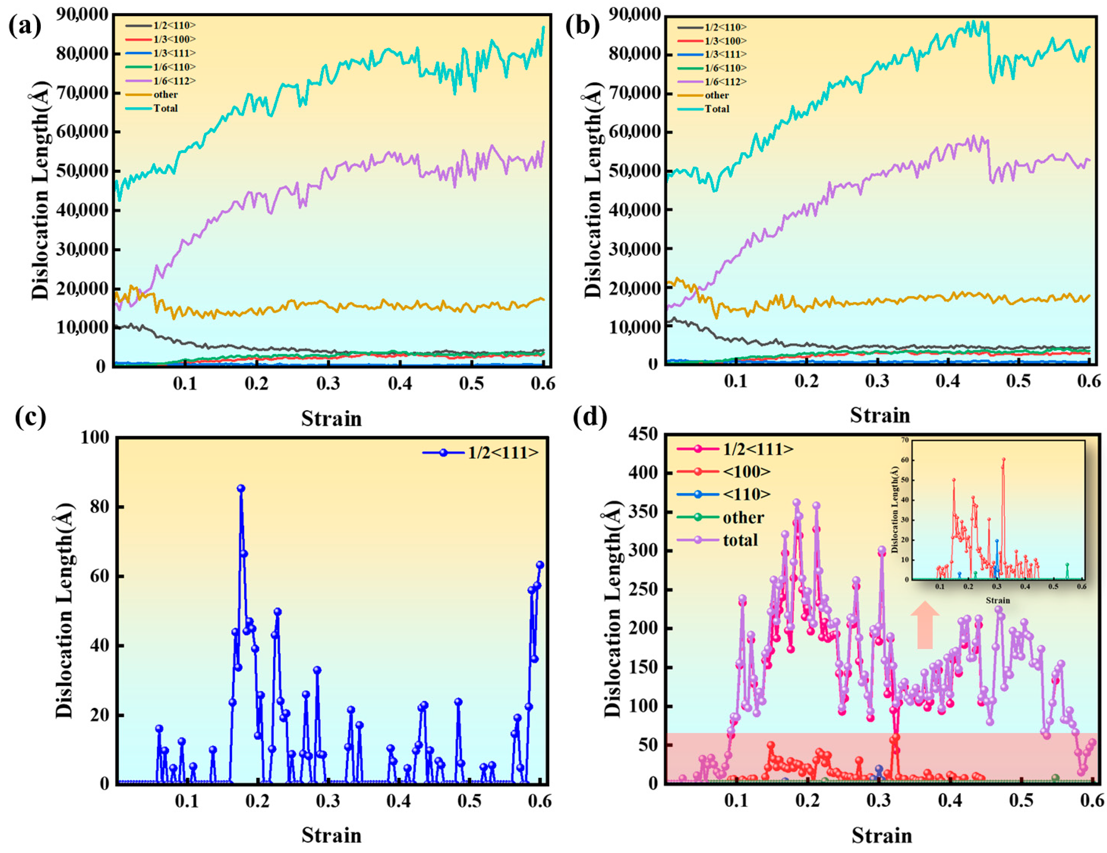
Multi-slip system coordination and complex dislocation interactions are the main mechanisms of strain hardening. In the dual-phase alloy, the FCC phase dominates plastic deformation, with dislocations propagating along the {110}<111> slip system to form SFs. The B2 phase enhances strength through the APB-dragging effect of superdislocation pairs. Dislocation interactions and double cross-slip phenomena significantly increase dislocation density, but excessive dislocation tangles lead to localized stress concentrations, becoming potential sites for crack nucleation.

Author Contributions

Conceptualization, J.R. and X.T.; methodology, Y.G. and W.X.; software, Y.G. and J.R.; validation, J.S. and Z.Z.; formal analysis, J.S.; investigation, X.L. and Z.Z.; data curation, J.S. and Z.Z.; writing—original draft preparation, Y.G.; writing—review and editing, W.X.; visualization, X.L.; supervision, J.R. and X.L.; project administration, X.T.; funding acquisition, J.R. All authors have read and agreed to the published version of the manuscript.

Funding

This project is financially supported by the Basic Research Innovation Group Project of Gansu Province (25JRRA803), the Major Science and Technology Project of Gansu Province (23ZDGA010), and the Gansu Province science and technology plan project (25CXGA049).

Data Availability Statement

The original contributions presented in this study are included in the article. Further inquiries can be directed to the corresponding authors.

Conflicts of Interest

Wang Xiang was employed by the No. 1 Steel making and Rolling Plant, Hunan Valin Lianyuan Iron and Steel Co., Ltd. The remaining authors declare that the research was conducted in the absence of any commercial or financial relationships that could be construed as a potential conflict of interest.

References

  1. Reed, R.C. The Superalloys: Fundamentals and Applications; Cambridge University Press: Cambridge, UK, 2008. [Google Scholar]
  2. Mu, Y.; Liang, Y.; Sheng, J.; Zhang, C.; Guo, Z.; Yang, G.; Sun, T.; Wang, Y.; Lin, J. A novel approach to coating for improving the comprehensive high-temperature service performance of TiAl alloys. Acta Mater. 2025, 283, 120500. [Google Scholar] [CrossRef]
  3. Ismail, F.; Vorontsov, V.; Lindley, T.; Hardy, M.; Dye, D.; Shollock, B.A. Alloying effects on oxidation mechanisms in polycrystalline Co–Ni base superalloys. Corros. Sci. 2017, 116, 44–52. [Google Scholar] [CrossRef]
  4. Blades, W.H.; Reinke, P. From alloy to oxide: Capturing the early stages of oxidation on Ni–Cr (100) alloys. ACS Appl. Mater. Interfaces 2018, 10, 43219–43229. [Google Scholar] [CrossRef] [PubMed]
  5. Gao, X.; Lu, Y.; Zhang, B.; Liang, N.; Wu, G.; Sha, G.; Liu, J.; Zhao, Y. Microstructural origins of high strength and high ductility in an AlCoCrFeNi2. 1 eutectic high-entropy alloy. Acta Mater. 2017, 141, 59–66. [Google Scholar] [CrossRef]
  6. Hong, Y.; Wang, C.; Lei, J.; Yang, T.; Ji, V.; Song, P.; Huang, T.; Zhang, X. Combined effect of B2 phase transformation and FCC/BCC lamellar structure on the mechanical property of heat treated dual-phase Al0. 7CoCrFeNi high entropy alloy. J. Alloys Compd. 2025, 1020, 179456. [Google Scholar] [CrossRef]
  7. Li, J.; Huang, Y.; Chen, C.; Zhang, L.; Zhang, L. The structural stability and mechanical properties of doped Al2Cu precipitates with different elements by first-principles calculations. Comput. Condens. Matter 2024, 41, e00957. [Google Scholar] [CrossRef]
  8. Chen, T.; Parish, C.M.; Yang, Y.; Tan, L. High-temperature strengthening mechanisms of Laves and B2 precipitates in a novel ferritic alloy. Mater. Sci. Eng. A 2018, 720, 110–116. [Google Scholar] [CrossRef]
  9. Li, Z.; Fu, L.; Peng, J.; Zheng, H.; Ji, X.; Sun, Y.; Ma, S.; Shan, A. Improving mechanical properties of an FCC high-entropy alloy by γ′ and B2 precipitates strengthening. Mater. Charact. 2020, 159, 109989. [Google Scholar] [CrossRef]
  10. Jiang, C.; Ma, H.; Chen, Y.; Wang, N.; Zhao, Q.; Wu, G.; Zhu, L.; Luo, J.; Zhao, Y. Crack propagation behavior of dual-phase steel at low temperature. Int. J. Fatigue 2022, 155, 106633. [Google Scholar] [CrossRef]
  11. Wu, S.; Qiao, X.; Zheng, M. Ultrahigh strength Mg-Y-Ni alloys obtained by regulating second phases. J. Mater. Sci. Technol. 2020, 45, 117–124. [Google Scholar] [CrossRef]
  12. Ye, Z.; Li, C.; Zheng, M.; Zhang, X.; Yang, X.; Wang, Q.; Gu, J. Realizing superior strength-ductility combination in dual-phase AlFeCoNiV high-entropy alloy through composition and microstructure design. Mater. Res. Lett. 2022, 10, 736–743. [Google Scholar] [CrossRef]
  13. Niu, M.; Qiu, S.; Yu, Q.; Li, W.; Zhang, S.; Guo, J.; Luan, J.; Wang, W.; Yang, T.; Wang, X. Achieving excellent elevated-temperature mechanical properties in dual-phase high-entropy alloys via nanoscale co-precipitation and heterostructure engineering. Acta Mater. 2025, 284, 120634. [Google Scholar] [CrossRef]
  14. Gao, B.; Hu, R.; Pan, Z.; Chen, X.; Liu, Y.; Xiao, L.; Cao, Y.; Li, Y.; Lai, Q.; Zhou, H. Strengthening and ductilization of laminate dual-phase steels with high martensite content. J. Mater. Sci. Technol. 2021, 65, 29–37. [Google Scholar] [CrossRef]
  15. Thompson, A.P.; Aktulga, H.M.; Berger, R.; Bolintineanu, D.S.; Brown, W.M.; Crozier, P.S.; In’, P.J.; Kohlmeyer, A.; Moore, S.G.; Nguyen, T.D. LAMMPS-a flexible simulation tool for particle-based materials modeling at the atomic, meso, and continuum scales. Comput. Phys. Commun. 2022, 271, 108171. [Google Scholar] [CrossRef]
  16. Hillel, G.; Galaeva, E.; Edry, I.; Fuks, D.; Pinkas, M.; Meshi, L. Understanding the formation mechanisms and stability of the Anti-Phase boundaries (APBs) in Al-Fe B2. J. Alloys Compd. 2024, 970, 172639. [Google Scholar] [CrossRef]
  17. Zhu, Y.; Wu, X. Perspective on hetero-deformation induced (HDI) hardening and back stress. Mater. Res. Lett. 2019, 7, 393–398. [Google Scholar] [CrossRef]
  18. Zhu, Y.; Wu, X. Heterostructured materials. Prog. Mater. Sci. 2023, 131, 101019. [Google Scholar] [CrossRef]
  19. Ji, W.; Zhou, R.; Vivegananthan, P.; Wu, M.S.; Gao, H.; Zhou, K. Recent progress in gradient-structured metals and alloys. Prog. Mater. Sci. 2023, 140, 101194. [Google Scholar] [CrossRef]
  20. Ren, J.; Gui, Y.; Gao, Q.; Wang, Q.; Bai, Y.; Li, J.; Xue, H.; Lu, X.; Tang, F. Mechanical response and plastic deformation in single-and dual-phase polycrystalline FeNiAl alloys: Molecular dynamics analysis. J. Mater. Sci. 2024, 59, 14405–14419. [Google Scholar] [CrossRef]
  21. Plimpton, S. Fast parallel algorithms for short-range molecular dynamics. J. Comput. Phys. 1995, 117, 1–19. [Google Scholar] [CrossRef]
  22. Faken, D.; Jónsson, H. Systematic analysis of local atomic structure combined with 3D computer graphics. Comput. Mater. Sci. 1994, 2, 279–286. [Google Scholar] [CrossRef]
  23. Stukowski, A.; Bulatov, V.V.; Arsenlis, A. Automated identification and indexing of dislocations in crystal interfaces. Model. Simul. Mater. Sci. Eng. 2012, 20, 085007. [Google Scholar] [CrossRef]
  24. Stukowski, A. Visualization and analysis of atomistic simulation data with OVITO–the Open Visualization Tool. Model. Simul. Mater. Sci. Eng. 2009, 18, 015012. [Google Scholar] [CrossRef]
  25. Farkas, D.; Caro, A. Model interatomic potentials for Fe–Ni–Cr–Co–Al high-entropy alloys. J. Mater. Res. 2020, 35, 3031–3040. [Google Scholar] [CrossRef]
  26. Hirel, P. Atomsk: A tool for manipulating and converting atomic data files. Comput. Phys. Commun. 2015, 197, 212–219. [Google Scholar] [CrossRef]
  27. Chen, C.; Gui, Y.; Tang, X.; Li, Y.; Wang, C.; Sheng, J.; Zhang, Z.; Lu, X.; Ren, J. Atomic-Scale Study on the Composition Optimization and Deformation Mechanism of FeNiAl Alloys. Metals 2025, 15, 460. [Google Scholar] [CrossRef]
  28. Shimokawa, T.; Fujii, K.; Niiyama, T. Atomic simulation study of the factors affecting nucleation in deformation-induced martensitic transformation in grains and at grain boundaries in pure iron. Acta Mater 2024, 265, 119629. [Google Scholar] [CrossRef]
  29. Rida, A.; Rouhaud, E.; Makke, A.; Micoulaut, M.; Mantisi, B. Study of the effects of grain size on the mechanical properties of nanocrystalline copper using molecular dynamics simulation with initial realistic samples. Philos. Mag. 2017, 97, 2387–2405. [Google Scholar] [CrossRef]
  30. Sumigawa, T.; Onozuka, S.; Kim, B.; Abe, M.; Shima, H.; Umeno, Y.; Kitamura, T. Unique damage process in micro-sized copper single crystal with double-slip orientation in response to near-[112] tension-compression fatigue. Mater. Sci. Eng. A 2024, 909, 146842. [Google Scholar] [CrossRef]
  31. Dong, S.; Liu, X.-Y.; Zhou, C. Atomistic modeling of plastic deformation in B2-FeAl/Al nanolayered composites. J. Mater. Sci. 2021, 56, 17080–17095. [Google Scholar] [CrossRef]
  32. Paidar, V.; Čák, M. Three types of dislocation core structure in B2 alloys. Intermetallics 2016, 73, 21–25. [Google Scholar] [CrossRef]
  33. Han, S.; Laube, S.; Chen, Z.; Kauffmann, A.; Heilmaier, M.; Inui, H. Operative slip system and dislocation behavior in a brittle refractory high-entropy alloy with the B2 ordered structure. J. Alloys Compd. 2025, 1020, 179361. [Google Scholar] [CrossRef]
  34. Li, Z.; Pradeep, K.G.; Deng, Y.; Raabe, D.; Tasan, C.C. Metastable high-entropy dual-phase alloys overcome the strength–ductility trade-off. Nature 2016, 534, 227–230. [Google Scholar] [CrossRef] [PubMed]
  35. Javanbakht, M.; Levitas, V.I. Interaction between phase transformations and dislocations at the nanoscale. Part 2: Phase field simulation examples. J. Mech. Phys. Solids 2015, 82, 164–185. [Google Scholar] [CrossRef]
  36. Javanbakht; Levitas, V.I. Phase field simulations of plastic strain-induced phase transformations under high pressure and large shear. Phys. Rev. B 2016, 94, 214104. [Google Scholar] [CrossRef]
  37. Fang, Q.; Chen, Y.; Li, J.; Jiang, C.; Liu, B.; Liu, Y.; Liaw, P.K. Probing the phase transformation and dislocation evolution in dual-phase high-entropy alloys. Int. J. Plast. 2019, 114, 161–173. [Google Scholar] [CrossRef]
  38. Lu, W.; Luo, X.; Yang, Y.; Zhang, J.; Huang, B. Huang. Effects of Al addition on structural evolution and mechanical properties of the CrCoNi medium-entropy alloy. Mater. Chem. Phys. 2019, 238, 121841. [Google Scholar] [CrossRef]
  39. Chen, S.; Aitken, Z.; Wu, Z.; Yu, Z.; Banerjee, R.; Zhang, Y. Hall-Petch and inverse Hall-Petch relations in high-entropy CoNiFeAlxCu1-x alloys. Mater. Sci. Eng. A 2020, 773, 138873. [Google Scholar] [CrossRef]
  40. Fang, Q.; Li, L.; Li, J.; Wu, H.; Huang, Z.; Liu, B.; Liu, Y.; Liaw, P.K. A statistical theory of probability-dependent precipitation strengthening in metals and alloys. J. Mech. Phys. Solids 2019, 122, 177–189. [Google Scholar] [CrossRef]
Figure 1. Dual-phase FeNiAl alloy model: (a) grain coloration in the model, Random distribution of grain color has no practical significance. (b) polycrystalline models with different B2-NiAl phase volume fractions, where green atoms represent FCC structure, blue atoms represent BCC structure (B2), red atoms represent HCP structure and stacking faults, and white atoms represent grain boundaries and other defects (Other). In the z-axis projections of atomic distributions, (c) orange represents iron (Fe) atoms, (d) green denotes nickel (Ni) atoms, (e) gray corresponds to aluminum (Al) atoms.
Metals 15 00738 g001
Figure 2. Flow chart from initial model generation to atomic structure optimization, application of boundary conditions, loading process, data acquisition and analysis.
Metals 15 00738 g002
Figure 3. Influence of B2 phase volume fraction on mechanical properties of FeNiAl alloys: (a) engineering stress–strain curves for B2 phase contents ranging from 2% to 15%; (b) engineering stress–strain curves for B2 phase contents between 20% and 50%; (c) comparative engineering stress–strain curves for alloys with 0%, 3%, and 5% B2 phase contents; (d) yield strength and tensile strength variations across different B2 phase volume fractions. The red stars represent the yield point, while the other colors indicate different strain points.
Metals 15 00738 g003
Figure 4. Deformation processes and dislocation motion in the alloy with 5% B2 phase volume fraction at varying strain: (a) ε = 0, (b) ε = 0.05, (c) ε = 0.06, (d) ε = 0.07, (e) ε = 0.08, (f) ε = 0.1. Green atoms represent FCC structure, blue atoms represent B2 structure, red atoms represent HCP structure and stacking faults, and white atoms represent grain boundaries and other defects (Other).
Metals 15 00738 g004
Figure 5. The transformation process of the alloy with a B2 phase volume fraction of 3% at different strains: (a) the initial model. The deformation of the FCC phase at different strains: (b) 0, (c) 0.05, (d) 0.06, (e) 0.1. The upper left corner illustration describes the double horizontal sliding process. The deformation of dislocation and B2 phase at different strains: (f) 0, (g) 0.05, (h) 0.06, (i) 0.1. Green atoms represent FCC structure, blue atoms represent B2 structure, red atoms represent HCP structure and stacking faults, and white atoms represent grain boundaries and other defects (Other).
Metals 15 00738 g005
Figure 6. Evolution of stress distribution contours in the alloys with 5% B2 phase volume fraction at different strains: (a1) 0, (b1) 0.05, (c1) 0.06, (d1) 0.07, (e1) 0.08, (f1) 0.1. Evolution of stress distribution contours in the alloys with 5% B2 phase volume fraction at different strains: (a2) 0, (b2) 0.05, (c2) 0.06, (d2) 0.07, (e2) 0.08, (f2) 0.1.
Metals 15 00738 g006
Figure 7. Analysis of the deformation process of the alloy with 5% B2 phase volume fraction under different strains: (a) 0, (b) 0.01, (c) 0.03, (d) 0.09, (e) 0.16, (f) 0.2, (g) 0.25, (h) 0.3. Green atoms represent FCC structure, blue atoms represent B2 structure, red atoms represent HCP structure and stacking faults, and white atoms represent grain boundaries and other defects (Other).
Metals 15 00738 g007
Figure 8. Phase fraction evolution in Fe90Ni9Al alloy during tensile deformation: (a) for 3% B2 phase volume fraction, (b) for 5% B2 phase volume fraction.
Metals 15 00738 g008
Figure 9. Dislocation length curves during tensile deformation of Fe90Ni9Al alloys with varying B2 phase volume fractions: (a) For the FCC phase in the alloy with 3% B2 phase volume fraction; (b) for the FCC phase in the alloy with 5% B2 phase volume fraction; (c) for the NiAl-B2 phase in the alloy with 3% B2 phase volume fraction; (d) for the NiAl-B2 phase in the alloy with 5% B2 phase volume fraction.
Metals 15 00738 g009
Figure 10. Antiphase boundaries (APBs) in the alloy with 3% B2 phase volume fraction: (a) Spatial distribution of APBs, (b) dislocation configuration analysis within APB regions and schematic illustration of superdislocation pairs. Green atoms represent FCC structure, blue atoms represent B2 structure, red atoms represent HCP structure and stacking faults, and white atoms represent grain boundaries and other defects (Other).
Metals 15 00738 g010
Figure 11. Fracture morphology of the Fe90Ni9Al alloy with 5% B2 phase volume fraction during tensile deformation (red atoms indicate tracked GB atoms) at different strains: (a) 0, (b) 0.05, (c) 0.1, (d) 0.15. Green atoms represent FCC structure, blue atoms represent B2 structure, red atoms represent HCP structure and stacking faults, and white atoms represent grain boundaries and other defects (Other). Dark red atoms are the atoms at the crack position of grain boundary after rendering.
Metals 15 00738 g011
Figure 12. Microstructure at 5% strain for Fe90Ni9Al alloys with B2 phase volume fractions: (a1) 0%, (a2) 3%, and (a3) 35%. Stress distribution at 5% strain for Fe90Ni9Al alloys with B2 phase volume fractions: (b1) 0%, (b2) 3%, and (b3) 35%. Dislocation types at 5% strain for Fe90Ni9Al alloys with B2 phase volume fractions: (c1) 0%, (c2) 3%, and (c3) 35%. In (b1b3), red atoms indicate high-stress regions while blue atoms denote low-stress regions. In (c1c4), dislocations are represented by line colors: perfect dislocations (dark blue lines), Shockley partial dislocations (green lines), Hirth dislocations (light yellow lines), stair-rod dislocations (pink lines), and Frank dislocations (light blue lines). Note: (c4) displays dislocations generated within the B2 phase in (c3).
Metals 15 00738 g012
Figure 13. Microstructural features of Fe90Ni9Al alloys with two different B2 phase volume fractions under varying strains. Microstructural features of the Fe90Ni9Al alloy with 0% B2 phase volume fraction at different strains: (a1) 0, (a2) 0.1, (a3) 0.2, (a4) 0.3. Microstructural features of the Fe90Ni9Al alloy with 20% B2 phase volume fraction at different strains: (b1) 0, (b2) 0.1, (b3) 0.2, (b4) 0.3. Green atoms represent FCC structure, blue atoms represent B2 structure, red atoms represent HCP structure and stacking faults, and white atoms represent grain boundaries and other defects (Other).
Metals 15 00738 g013
Disclaimer/Publisher’s Note: The statements, opinions and data contained in all publications are solely those of the individual author(s) and contributor(s) and not of MDPI and/or the editor(s). MDPI and/or the editor(s) disclaim responsibility for any injury to people or property resulting from any ideas, methods, instructions or products referred to in the content.

