Abstract
Ni–P–WC–BN(h) nanocomposite coatings were fabricated on 20CrMnTi substrates using ultrasonic-assisted pulsed electrodeposition. 20CrMnTi is a low-carbon steel that is commonly used in the manufacturing gears and shaft components. To enhance the wear resistance and extend the service life of such mechanical parts, ultrasonic-assisted pulsed electrodeposition was employed as an effective surface modification technique. The microhardness, phase structure, surface morphology, and wear behavior of the coating were also characterized. An orthogonal experimental design was employed to examine the effects of current density, bath temperature, ultrasonic power, and pulse duty cycle on the microhardness and wear behavior of the coatings, aiming to optimize the deposition parameters. The optimal process combination was identified as a current density of 3 A·dm−2, a bath temperature of 55 °C, an ultrasonic power of 210 W, and a duty cycle of 0.7. Under these conditions, the coatings exhibited enhanced hardness and wear resistance. Based on the optimized parameters, additional tribological tests were conducted under various operating conditions to further evaluate wear performance. The results showed that the dominant wear mechanisms were chemical wear and adhesive wear. This study offers new insights into the fabrication of high-performance nanocomposite coatings and expands the application scope of ultrasonic-assisted pulsed electrodeposition in multiphase composite systems.
1. Introduction
With the rapid development of industrial technology, electrodeposition has played a vital role in enhancing the corrosion resistance, wear resistance, and electrical conductivity of metallic materials, thereby extending the service life of easily worn mechanical components such as gears and shafts [1]. This method has attracted widespread attention due to its simplicity, low cost, and ability to produce high-performance coatings. The incorporation of BN(h) nanoparticles into Ni–P–WC composite coatings has been of particular interest due to their ability to modify the coating structure and frictional properties while providing a lubricating effect. This addition helps reduce the coefficient of friction and wear volume without compromising the hardness of the coating [2,3]. Moreover, variations in process parameters electrodeposition parameters can significantly influence the microstructure and functional properties of metal matrix composite coatings [4,5].
In recent years, numerous studies have focused on optimizing coating properties by adjusting electrodeposition process parameters. Liu et al. [6] conducted orthogonal experiments to optimize pulsed electrodeposition conditions for Ni–TiN–CeO2 coatings and found that these conditions led to significant grain refinement and densification of the nickel matrix, thereby improving the surface morphology. Pan et al. [7] investigated the effects of processing parameters on the surface roughness of LD10 aluminum alloy coatings under positive and negative pulsed power in an alkaline electrolyte. They found that both duty cycle and frequency had a marked impact on surface roughness, which decreased with a lower duty cycle or a higher frequency. Zhang et al. [8] prepared Ni–Co–W–Al2O3 composite coatings via electrodeposition and studied how current density and electrolyte composition affected the elemental distribution, microstructure, and wear behavior. Their findings indicated that variations in current density altered the surface morphology and nanoparticle content, thereby influencing the surface performance of the coating. In addition, the type of pulse current significantly influenced microstructural characteristics. It has been shown that lattice orientation, distortion, and grain size vary with current mode, where pulsed and reverse-pulsed currents tend to induce higher lattice distortion and finer grains, respectively [9]. Furthermore, process parameters also affect wear behavior by modulating particle morphology, degree of grain refinement, nanoparticle dispersion, and crystallographic structure, collectively contributing to improved durability and extended service life [10,11,12].
Despite significant advancements in the fabrication of composite coatings via electrodeposition, studies on optimizing the process parameters for ultrasonic-assisted pulsed electrodeposition of Ni–P–WC–BN(h) composite coatings remain limited. To address this research gap, the study fabricates Ni–P–WC–BN(h) composite coatings via ultrasonic pulsed electrodeposition and to systematically evaluate the effects of key process parameters—including bath temperature, duty cycle, pulse frequency, and current density—on the resulting microstructure, microhardness, and wear behavior. This work is expected to provide both a theoretical foundation and experimental reference for the development of high-performance Ni–P–WC–BN(h) coatings with optimized properties.
2. Materials and Methods
2.1. Preparation of Coating
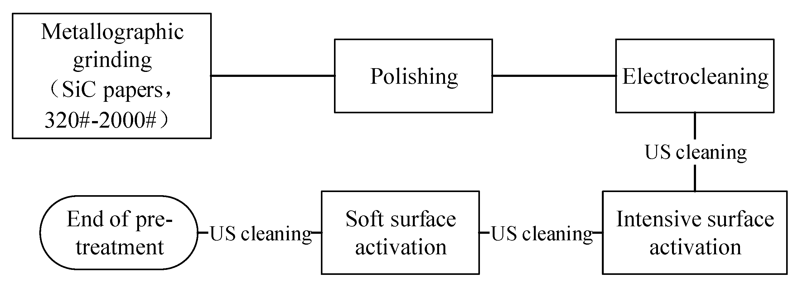
20CrMnTi steel substrates measuring 40 mm × 16 mm × 12 mm were employed in this study, as illustrated in Figure 1. The electroplating pretreatment procedure is schematically presented in Figure 2.

Figure 1.
Sample grinding and polishing shielding process diagram.
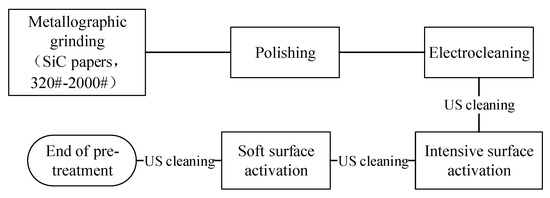
Figure 2.
Flow chart of the preliminary experiment.
The optimal concentrations of BN(h) and WC nanoparticles were determined to be 25 g·L−1 and 30 g·L−1, respectively. Both nanoparticle types exhibited a purity of 99.9% and an average particle size of approximately 50 nm. The composition of the base coating solution is summarized in Table 1.

Table 1.
Composition of basic coating solution.
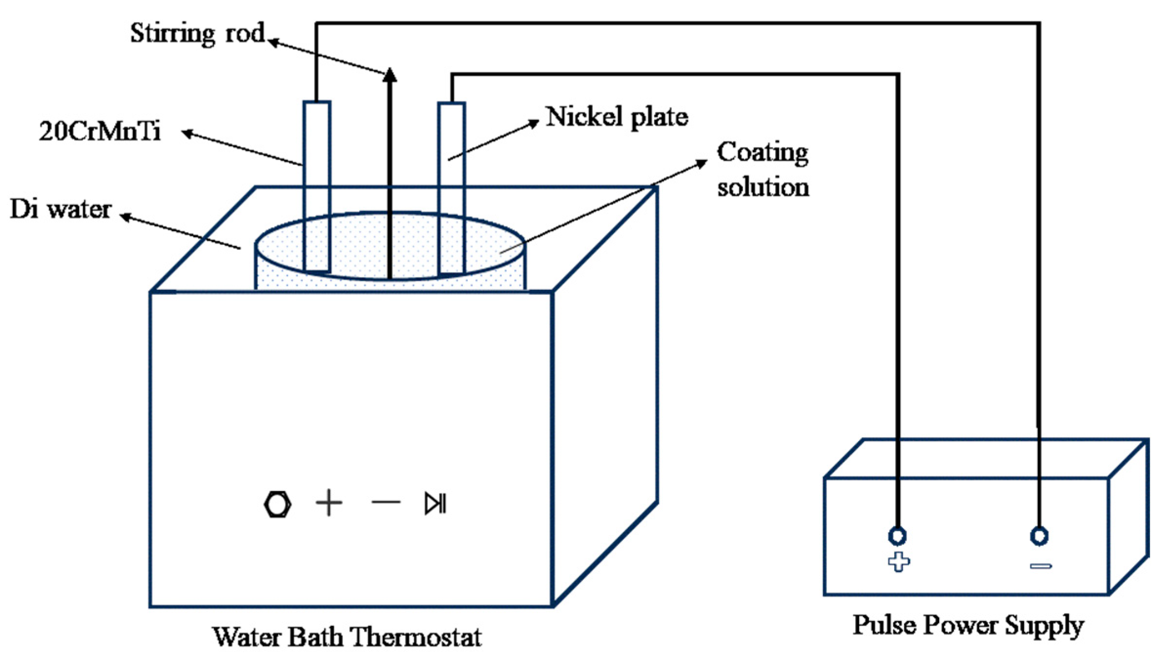
The electrodeposition system employed a pulsed power supply, enabling precise control of current density and duty cycle. The electro-deposition system includes a pulse power supply, a constant-temperature water bath with ultrasonic capabilities, and a mechanical stirrer. A pure nickel plate was used as the anode, while the cathode was the 20CrMnTi steel substrate on which the composite coatings were deposited, as illustrated in Figure 3.
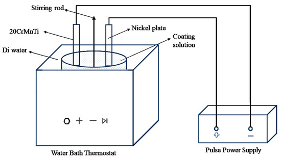
Figure 3.
Schematic diagram of the experimental setup.
In this experimental study, four primary process parameters were selected to determine the optimal electrodeposition conditions for Ni–P–WC–BN(h) nanocomposite coatings: current density (A), bath temperature (B), ultrasonic power (C), and pulse duty cycle (D). Each factor was evaluated at three distinct levels, as presented in Table 2. A four-factor, three-level orthogonal array design, denoted as L9(34), was employed, as detailed in Table 3. Each trial in the L9(34) matrix represented a unique combination of parameters, enabling a systematic evaluation of the influence of each factor on coating performance. According to Archard’s equation, the microhardness of a coating is directly proportional to its wear resistance. Therefore, microhardness was selected as the evaluation index to determine the optimal combination of process parameters [13].

Table 2.
Orthogonal test factor level table.

Table 3.
Orthogonal test table.
2.2. Characterization of Coating Properties
The microhardness of the coatings was measured using a Duramin-40A1 microhardness tester (Struers, Ballerup, Denmark) under a load of 1000 gf with a dwell time of 10 s. Five measurements were performed at different locations on each sample, and the average value was recorded. The surface morphology and elemental distribution of the coatings were examined using a field emission scanning electron microscope (SEM, Carl Zeiss, Jena, Germany) equipped with an energy-dispersive spectroscopy (EDS) system. The crystalline structure of the composite coatings was analyzed using an X-ray diffractometer (XRD, Rigaku SmartLab SE, Tokyo, Japan). The coefficient of friction (COF) was evaluated using a comprehensive surface property tester (CFT-I, Lanzhou Zhongke Kaihua Technology, Lanzhou, China) under a line contact configuration. A Si3N4 ball (diameter = 4 mm; surface roughness, Ra = 0.06 µm; microhardness = 1400–1700 HV1) was used as the counter body. The applied normal load was 320 g, and reciprocating tests were conducted at frequencies of 200, 400, and 600 times/min. The surface morphology of the wear scar and the cross-sectional profile were obtained using a SEM and a stereo microscope (Nexcope NSZ818M, Ningbo, China), respectively. The wear loss volume was measured using the stereo microscope, and the wear rate was subsequently calculated.
3. Results and Discussion
3.1. Optimization Design
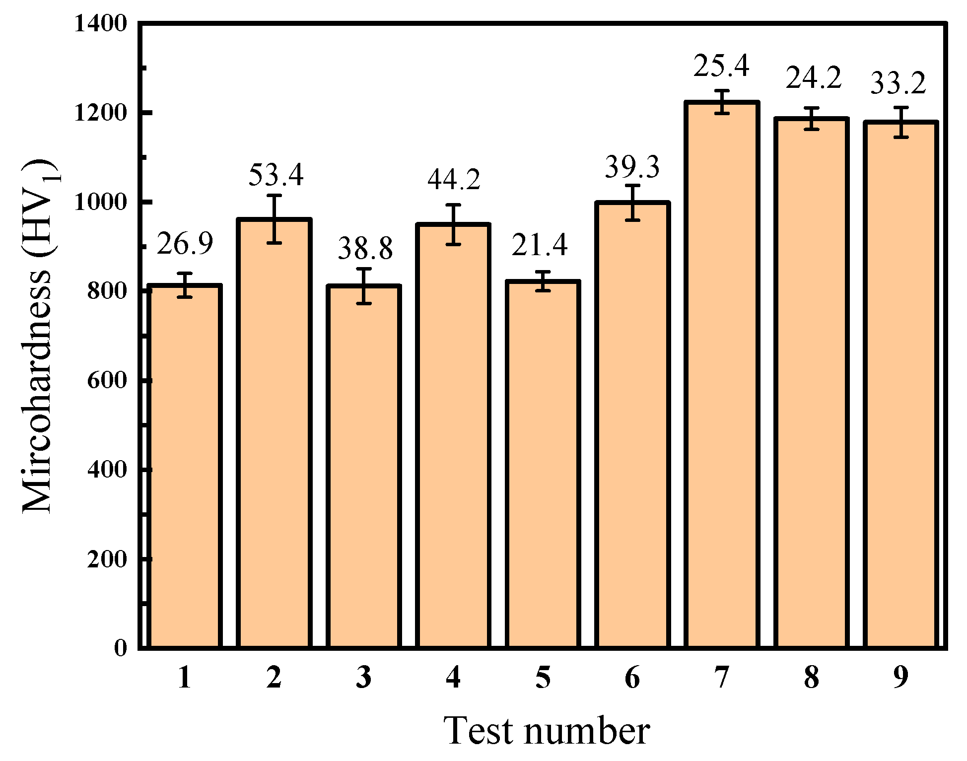
Table 4 and Figure 4 illustrate the average surface microhardness and the maximum deviation of the Ni–P–WC–BN(h) nanocomposite coatings under various process parameter combinations. Data points 1 to 9 correspond to the nine experimental conditions defined in the L9(34) orthogonal array. As shown in Figure 4, different combinations of process parameters have a pronounced influence on surface microhardness of the coatings. The overall microhardness values fluctuate within the range of 811.5 HV1 to 1223.7 HV1, indicating that process optimization plays a crucial role in enhancing the mechanical performance of the coatings.

Table 4.
Test results and polar analysis of variance.
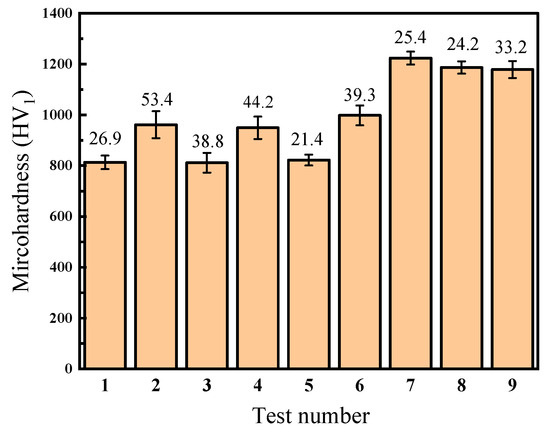
Figure 4.
Microhardness value of composite coating with different process parameters.
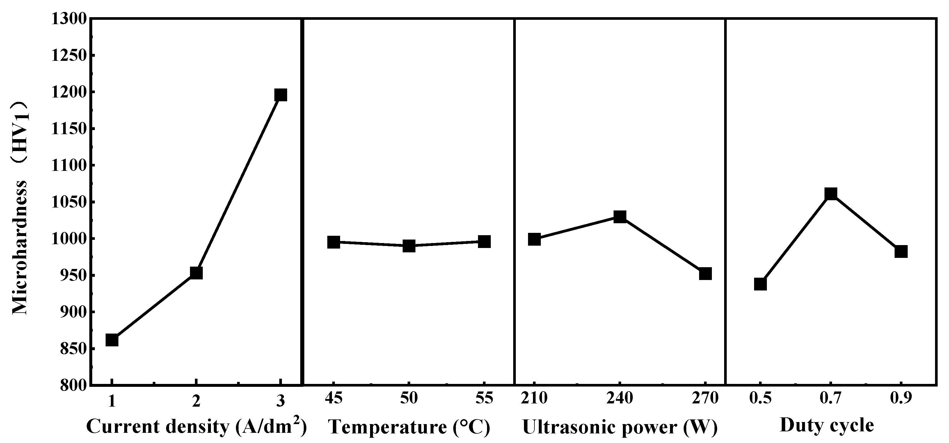
Addtionally, Table 4 summarizes the results of the range (polar) analysis, illustrating the influence of each electrodeposition parameter on the microhardness of the Ni–P–WC–BN(h) nanocomposite coatings. The corresponding trends are depicted in Figure 5, which provides an intuitive visualization of how current density, bath temperature, ultrasonic power, and pulse duty cycle affect the performance of coating, the figure also highlights the optimal level of each parameter and its relative impact on the mechanical properties of the coatings.
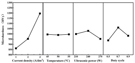
Figure 5.
Orthogonal Test Level Trend Plot.
Based on the trend analysis, the influence of the four process parameters on microhardness follows the descending order: current density > duty cycle > ultrasonic power > temperature. These results indicate that current density is the dominant factor affecting the overall performance of the Ni–P–WC–BN(h) coatings.
When the current density was set at 1 A·dm−2, the overall surface microhardness of the coating remained relatively low, generally below 1000 HV1. This can be attributed to the insufficient electric field strength, which limits the mobility of nanoparticles in the electrolyte and weakens the electrostatic attraction at the cathode. As a result, the deposition reaction proceeds at a slower rate, hindering the formation of a uniform and continuous coating layer and thereby providing limited protection to the substrate [14]. As the current density increased, the surface microhardness of the composite coatings exhibited a clear upward trend. This enhancement is primarily due to the accelerated deposition rate at higher current densities, which promotes the formation of a denser and more compact coating structure, ultimately improving the microhardness [15,16,17].
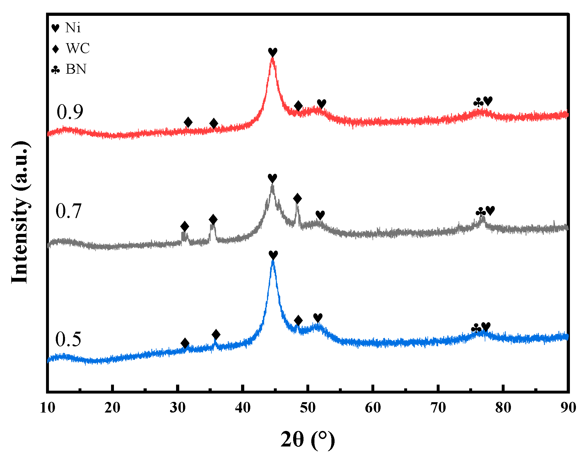
The pulse duty cycle is the second most significant factor affecting the microhardness of the coating, following current density. As the duty cycle increases from 0.5 to 0.9, the microhardness first increases and then decreases, reaching its maximum at a duty cycle of 0.7. As shown in Figure 6, at a duty cycle of 0.7, the XRD main peak exhibits relatively higher intensity and a moderate full width at half maximum (FWHM), indicating a smaller grain size and a denser crystalline structure under this condition. This optimal duty cycle facilitates nucleation while effectively suppressing grain growth, thereby promoting grain refinement and the formation of a compact crystalline structure. Additionally, a higher duty cycle increases the number of surface defects on metal grains, which can serve as additional nucleation sites for Ni2+ deposition [18,19]. In contrast, excessively low duty cycle may lead to dendritic crystal formation, which compromises the compactness of the coating and results in reduced microhardness [20]. Furthermore, the effects of ultrasonic power and bath temperature on microhardness are relatively limited, indicating that their influence on the overall performance of the coating is significantly lower than that of current density and duty cycle.
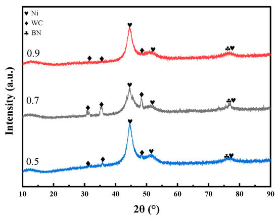
Figure 6.
XRD patterns of the coatings prepared under identical deposition conditions with duty cycles of 0.5, 0.7, and 0.9.
As the ultrasonic power increases, the microhardness of the coating first rises and then decreases, reaching a maximum at 240 W. This is attributed to the enhancement of cavitation effects in the electrolyte by ultrasonic energy, which promotes the uniform dispersion of nanoparticles and increases the nucleation rate, thereby improving hardness [21]. Relevant studies have shown that excessively high ultrasonic power can lead to intense cavitation, resulting in surface disturbances and increased porosity, which in turn cause a reduction in microhardness [22]. When the deposition temperature is 55 °C, the microhardness of coating is slightly higher than that obtained at 45 °C and 50 °C. However, compared with ultrasonic power and duty cycle, the overall influence of temperature on microhardness is relatively limited, showing a less pronounced variation. Similar phenomena have been reported in other coating systems, suggesting that within a certain range, deposition temperature may cause a slight increase in microhardness, though its effect is generally weaker than that of other parameters [23].
To further quantify the significant effects of composite electrodeposition parameters on coating performance, analysis of variance (ANOVA) was conducted based on the orthogonal experimental results. This approach was used to verify the reliability of the conclusions obtained from the range analysis and to provide more intuitive and rigorous data support as well as theoretical basis for optimizing the electrodeposition process of Ni–P–WC–BN(h) nanocomposite coatings. The significance level was set at P = 0.1.
To quantify the overall deviation of the factors from the sample, the sum of squares of deviations (SS) for each factor was calculated. This calculation involved determining the mean of each group of values, then computing the squared differences between each individual value and its group mean. The sum of these squared differences was used to express the SS for each factor, as follows:
k—number of tests;
nj—value of the jth group;
Xij—the ith value of the jth group;
Xj—mean of the jth group.
The mathematical expression for the degree of freedom (df) is:
df = k − 1
The mathematical expression for the mean square (MS) is:
The mathematical expression for the value of F is:
where MSe-mean square of error.
The sum of squares (SS), degrees of freedom (df), mean squares (MS), and F-values were calculated and analyzed using ANOVA, based on Equations (1)–(4), to evaluate the significance of the effect exerted by each process parameter on the microhardness of the coating.
The ANOVA results are presented in Table 5. In the analysis of microhardness, current density exhibited the most significant influence on the coating microhardness. Variations in current density directly influence the transport rate and adsorption behavior of nanoparticles, which subsequently determined the nanoparticle content within the coating and thereby affected its microhardness [24]. The duty cycle and ultrasonic power showed moderate effects, whereas bath temperature exhibited no statistically significant impact. This observation is consistent with the results of the range analysis.

Table 5.
Data table of ANOVA results.
By combining the results of both range and variance analyses, the order of influence of each parameter on microhardness was determined to be: current density > duty cycle > ultrasonic power > temperature. This provides a theoretical basis for determining the optimal process parameters for the preparation of Ni–P–WC–BN(h) nanocomposite coatings.
Four process parameters were selected for optimization using the L9(34) orthogonal array: current density, temperature, ultrasonic power, and duty cycle. The optimal parameter combination was identified as a current density of 3 A·dm−2, a bath temperature of 55 °C, an ultrasonic power of 210 W, and a pulse duty cycle of 0.7. Coating samples were fabricated under these optimized conditions, and the microstructure and mechanical characteristics of the Ni–P–WC–BN(h) nanocomposite coatings were subsequently analyzed.
3.2. XRD Analysis
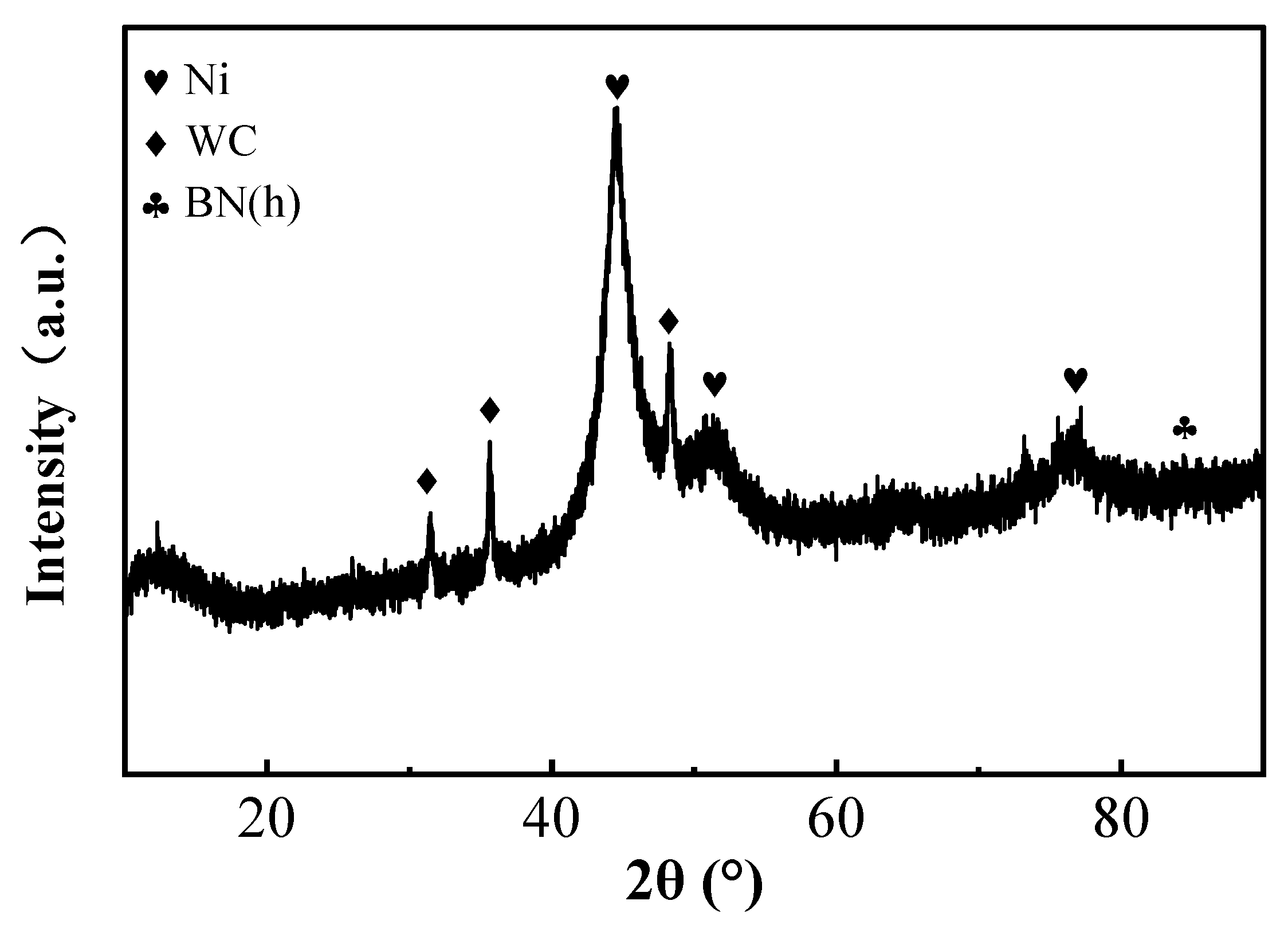
The XRD patterns of the coatings prepared under optimal process conditions are presented in Figure 7. As shown in the figure, distinct diffraction peaks of metallic Ni appear at 2θ values of 44.507°, 51.846°, and 76.370°, corresponding to the (111), (200), and (220) crystal planes of Ni, respectively. These peaks exhibit a pronounced (111) preferred orientation, indicating that the coating is mainly composed of crystalline Ni phase. In addition, characteristic peaks of WC are detected at 2θ values of 31.474°, 35.626°, and 48.266°, confirming the successful incorporation of WC nanoparticles into the composite coating. However, the absence of clear BN(h) diffraction peaks in the XRD spectrum may be attributed to the highly amorphous nature or the low-crystallinity nanocrystalline structure of the BN nanoparticles in the coating. Their small size and lack of long-range order prevent the generation of distinct XRD peaks [25,26].
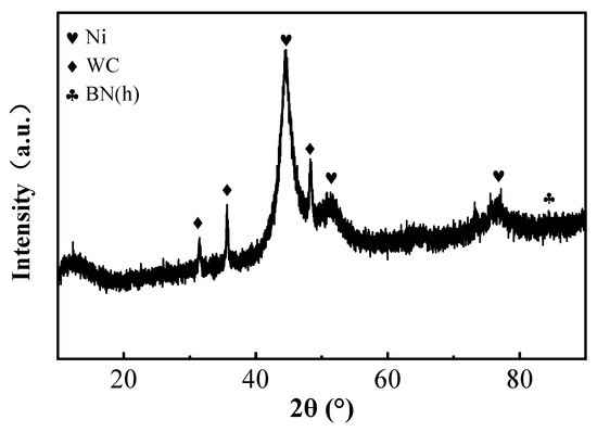
Figure 7.
XRD spectra of the surface coating.
3.3. Surface and Cross-Sectional Morphology
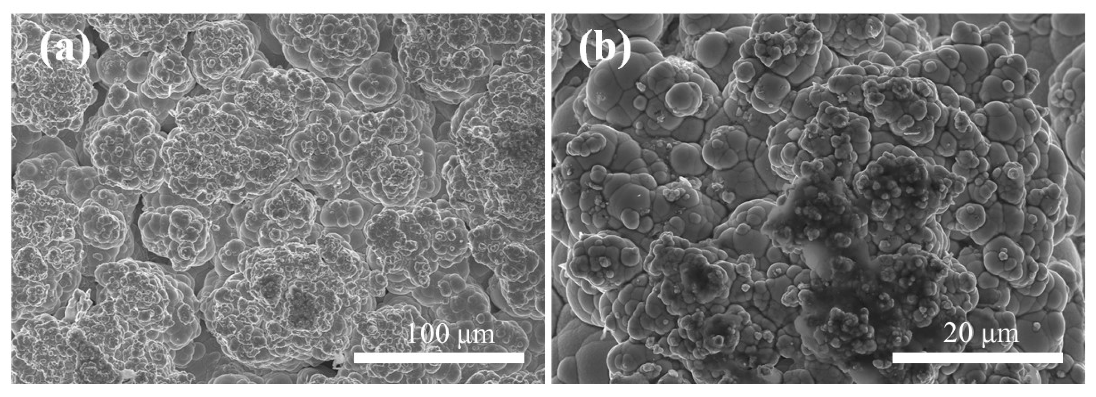
Figure 8a,b display the surface microstructure of Ni–P–WC–BN(h) nanocomposite coatings prepared under the optimal process conditions. The surface exhibits distinct and uniform cellular structures, which are characteristic of nickel-based coatings.
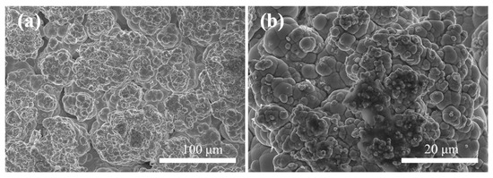
Figure 8.
Scanning electron microscope images of Ni–P–WC–BN(h) (a) 500× (b) 2000×.
Following the incorporation of BN(h) and WC nanoparticles, the composite coating presents significant grain refinement. This refinement is primarily attributed to the strong stirring action induced by ultrasonic agitation, which facilitates the macroscopic uniform dispersion of nanoparticles in the electrolyte solution [27]. Additionally, WC and BN(h) nanoparticles serve as heterogeneous nucleation centers, providing abundant nucleation sites and suppressing the growth of nickel grains, which results in a finer-grained coating structure [28,29]. Furthermore, the synergistic effect between the nanoparticles and current density [30] enhances the nucleation rate while effectively inhibiting grain coarsening. As a result, the coating exhibits a hierarchical morphology, with larger cellular structures overlaid by finer substructures, contributing to improved structural compactness and uniformity.
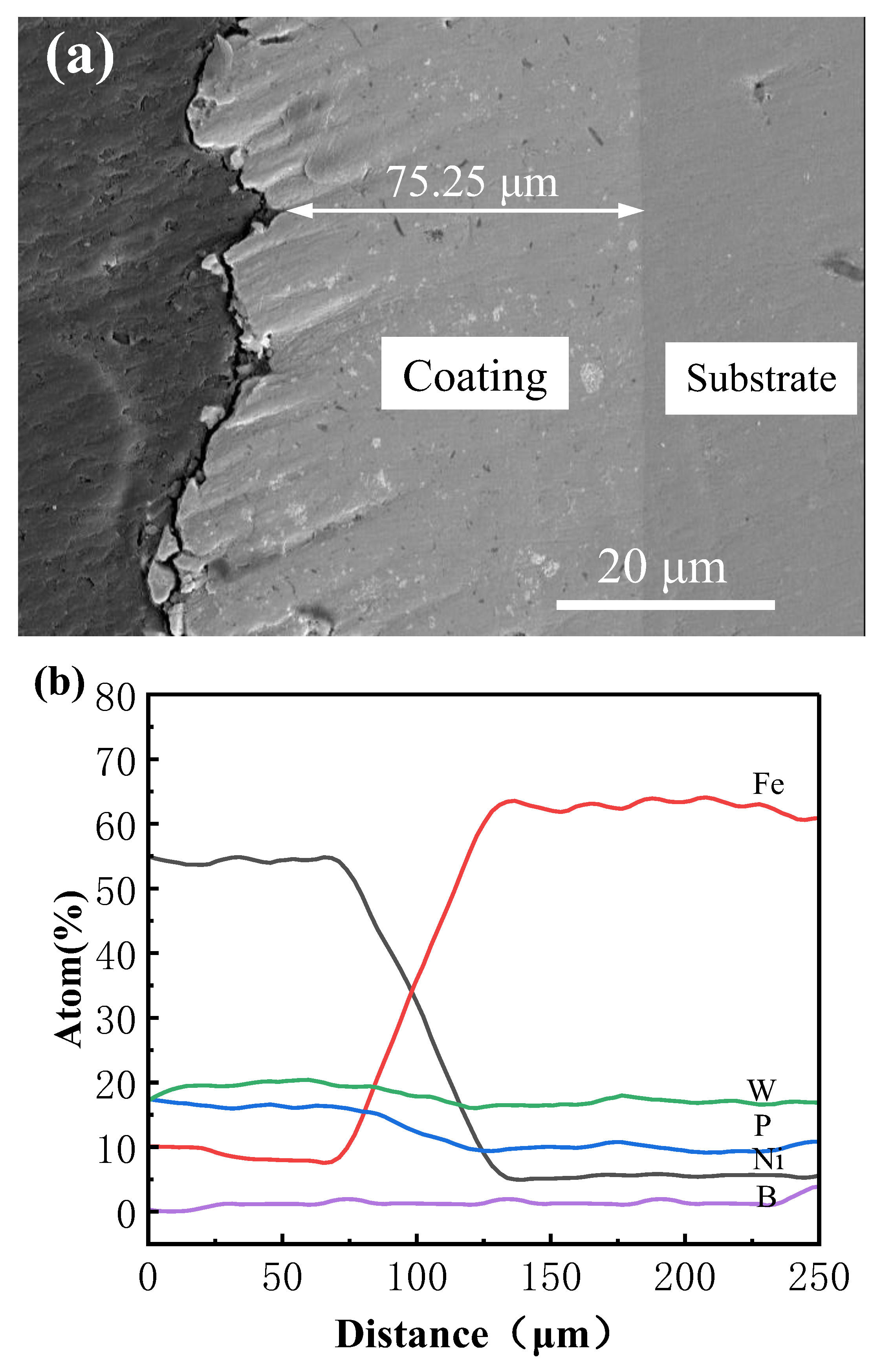
Under the optimized process parameters, the elements within the coating region are uniformly distributed, and the internal composition remains consistent. No evident agglomeration or compositional segregation is observed, demonstrating both the feasibility and stability of the electrodeposition process. Concurrently, improvements in coating strength and microhardness are achieved. Figure 9 presents the cross-sectional morphology and elemental distribution based on EDS line scanning of the Ni–P–WC–BN(h) nanocomposite coating. The coating exhibits a uniform thickness of approximately 75.25 μm, with no visible voids or cracks at the interface between the coating and the substrate. The application of ultrasonic-assisted pulsed electrodeposition under optimized parameters effectively minimizes interfacial defects and enhances coating quality. As shown in Figure 5, a transition zone is identified between 75 μm and 125 μm, where elemental concentrations fluctuate slightly and subsequently stabilize beyond 130 μm.
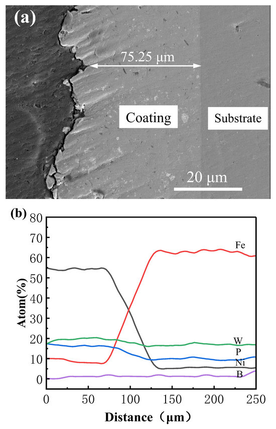
Figure 9.
(a) Scanning electron microscope image of Ni-P-WC-BN (h) cross-section, (b) EDS line scan image.
3.4. Microhardness
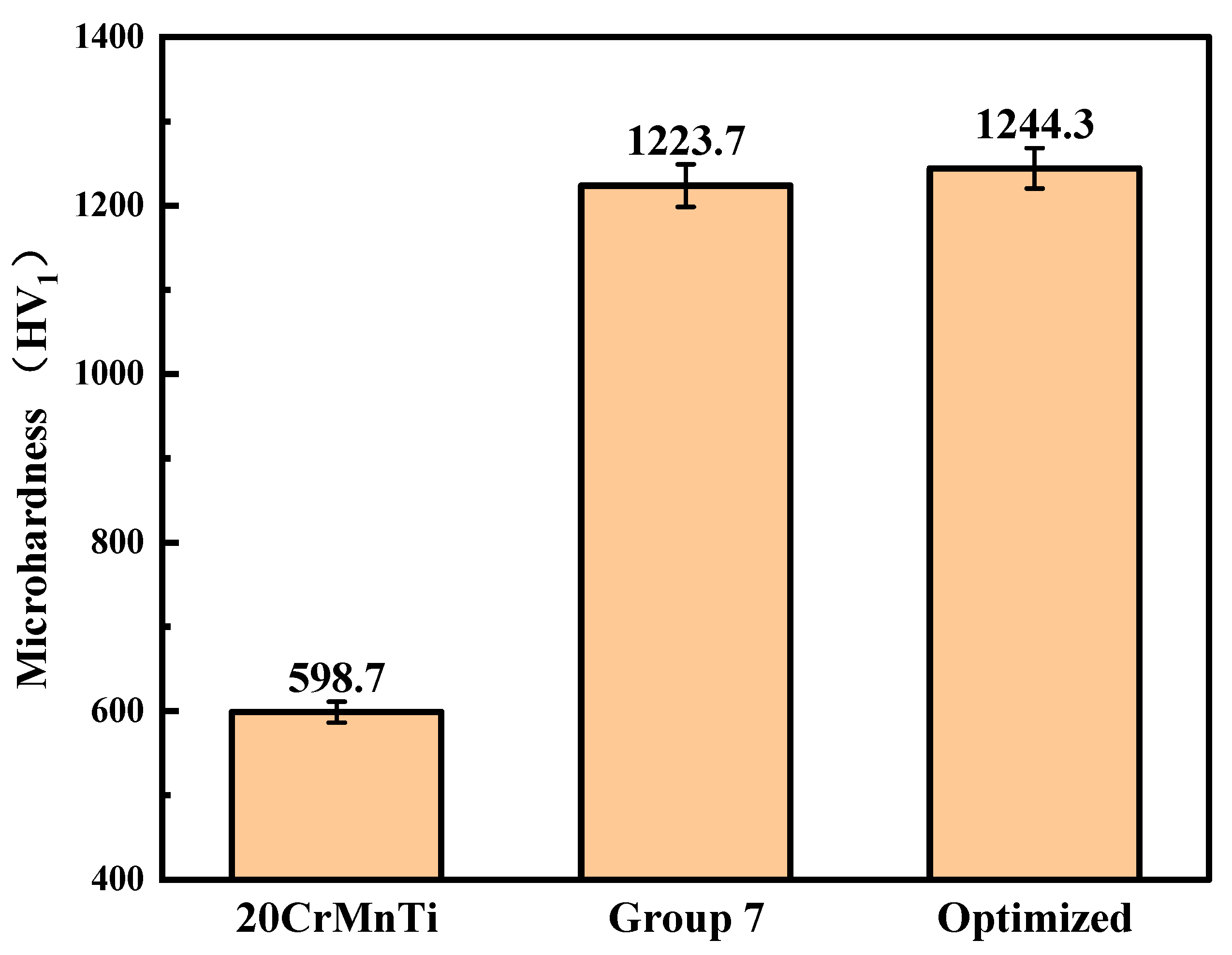
Figure 10 illustrates the microhardness of Ni–P–WC–BN(h) nanocomposite coatings obtained under the optimized process conditions. The average microhardness of the coating reaches 1244.3 HV1, in contrast to 598.7 HV1 measured for the 20CrMnTi substrate. This represents an approximate twofold increase in surface hardness compared to the uncoated substrate. Compared with the highest-microhardness group in the orthogonal optimization tests, the microhardness increased by approximately 1.7%.
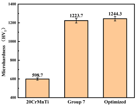
Figure 10.
Comparison of the microhardness of the optimized coating, Group 7, and the substrate.
The improvement in microhardness is primarily attributed to the uniform dispersion of WC and BN(h) nanoparticles within the coating, which provides dispersion strengthening. These nanoparticles also function as heterogeneous nucleation sites, promoting grain refinement during the electrodeposition process. As a result, the coating benefits from fine-grain strengthening, leading to enhanced surface strength and hardness [31,32]. The application of the optimized process parameters enables the fabrication of Ni–P–WC–BN(h) nanocomposite coatings with significantly improved microhardness, demonstrating the effectiveness of the proposed method.
3.5. Wear Behavior
To further investigate the tribological behavior of the Ni–P–WC–BN(h) nanocomposite coatings under the optimized process conditions, wear tests were carried out at different reciprocating speeds. The objective of this analysis was to evaluate the influence of sliding speed on the frictional characteristics and wear resistance of the coatings. All tests were performed under a constant normal load of 320 g, with reciprocating speeds set at 200, 400, and 600 times/min. These conditions were selected to assess the effects of varying reciprocating speeds on the COF and wear scar morphology of the composite coating.
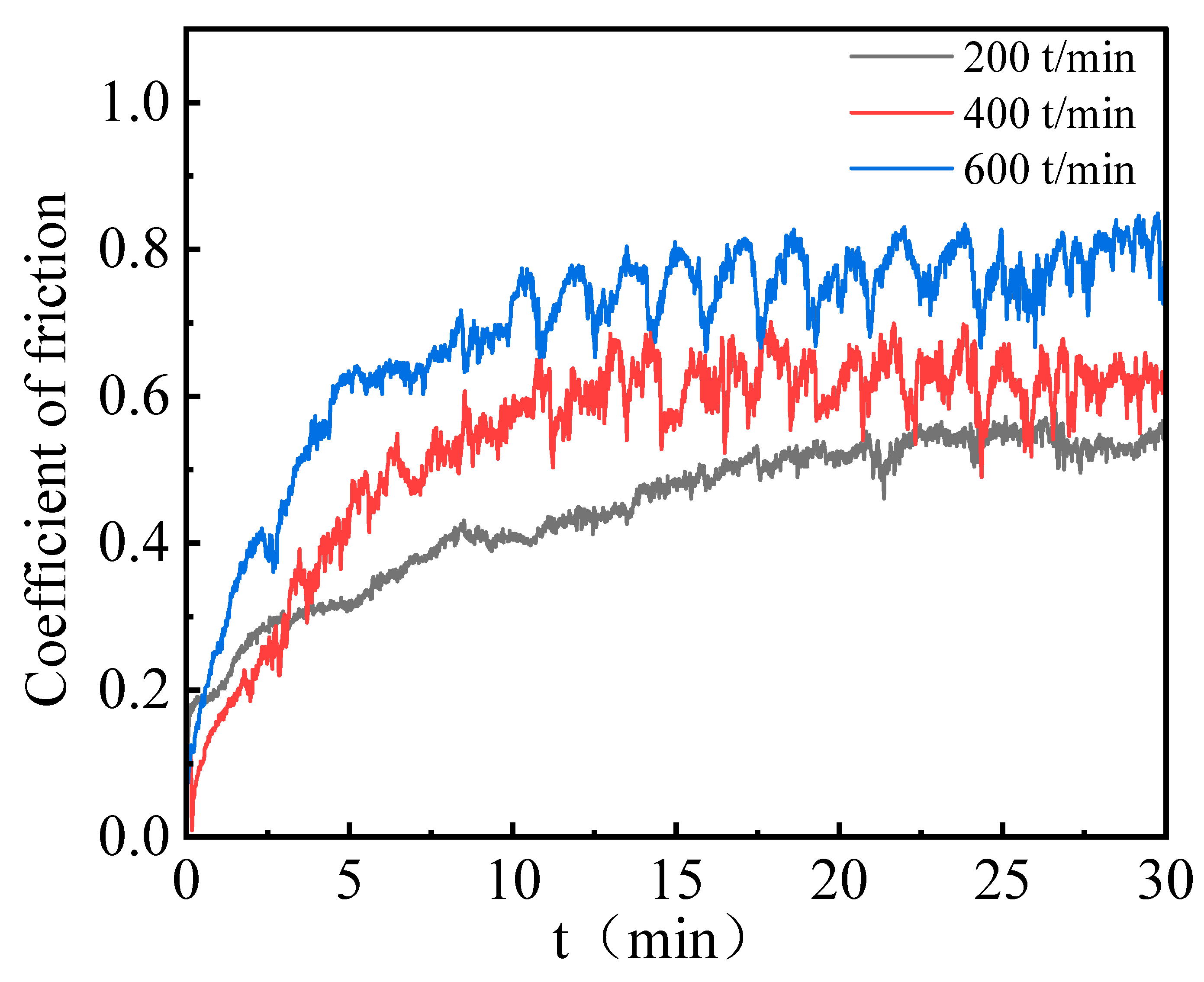
Figure 11 compares the COF of Ni–P–WC–BN(h) nanocomposite coatings under different reciprocating speeds. The corresponding COF values are 0.45, 0.54, and 0.68 at 200, 400, and 600 times/min, respectively. The results reveal a clear upward trend in COF with increasing reciprocating speed. Moreover, the rate of increase becomes more pronounced at higher speeds, indicating that elevated reciprocating frequencies intensify the frictional response of the coating surface.
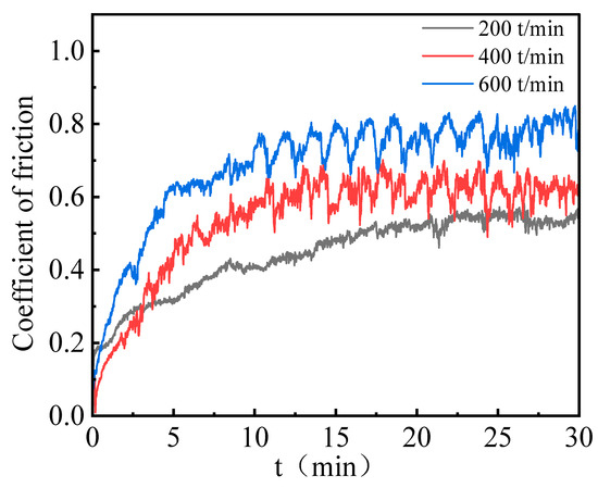
Figure 11.
COF results of Ni–P–WC–BN(h) nanocomposite coatings with different reciprocating speeds.
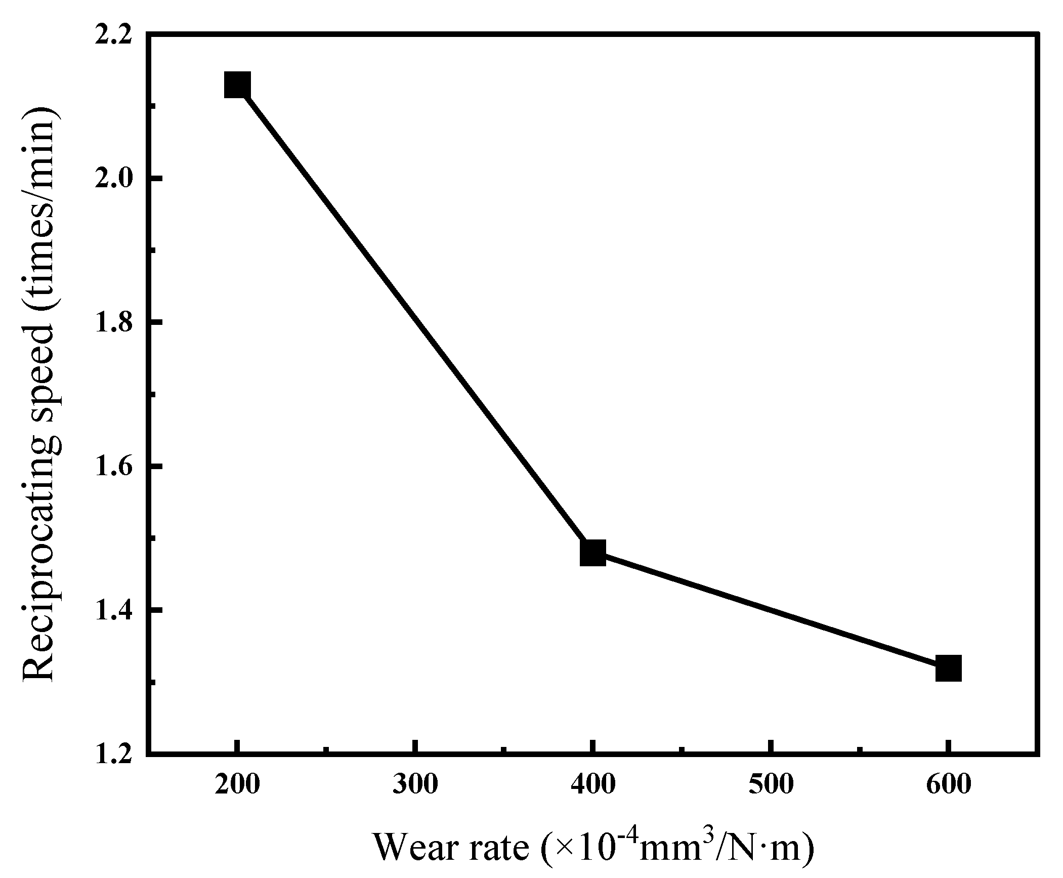
Figure 12 and Table 6 present the wear rates of Ni–P–WC–BN(h) nanocomposite coatings under different reciprocating speeds. The results indicate that the wear rate of the coating generally decreases with increasing ball speed, and the reduction exhibits a nonlinear trend. This may be attributed to insufficient frictional heat at low speeds, which slows down the formation of an oxide film and results in direct metal-to-metal contact, leading to a higher wear rate. As the friction speed increases, the heat generated facilitates the formation of a transfer film on the surface, which helps alleviate further wear [33].
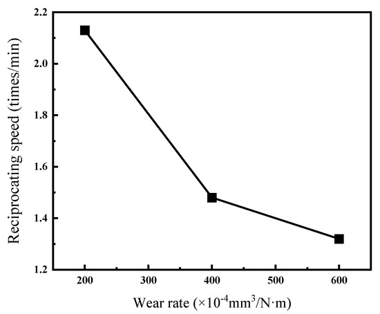
Figure 12.
Wear rates of Ni–P–WC–BN(h) nanocomposite coatings under different reciprocating speeds.

Table 6.
Wear of composite coating at different reciprocating speeds.
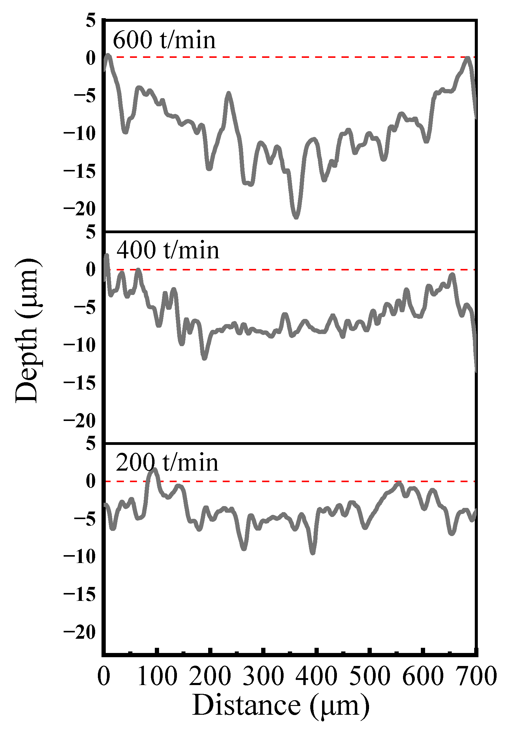
Figure 13 presents the cross-sectional profiles of abrasion marks observed on Ni–P–WC–BN(h) nanocomposite coatings under different reciprocating speed conditions. In the initial stage of wear, the counter ball exerts localized pressure on the coating surface, resulting in slight plastic deformation and the generation of wear debris. These debris particles subsequently engage in the wear process, and under the action of hard particles, micro-furrows gradually develop on the coating surface. The presence of abrasive wear is evident in Figure 13.
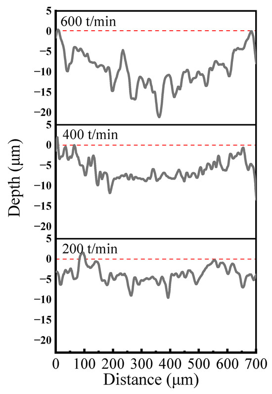
Figure 13.
Cross-section curves of abrasion marks at different reciprocating speeds.
Figure 14 shows the variation in abrasion mark dimensions of Ni–P–WC–BN(h) nanocomposite coatings prepared under the optimized process parameters, at different reciprocating speeds. Subfigures (a), (b), and (c) correspond to tests conducted at 200, 400, and 600 times/min, respectively. As illustrated, both the depth and width of the abrasion marks increase significantly with higher reciprocating speeds. This trend is attributed to the increased frictional force experienced by the coating surface, leading to more severe material removal.

Figure 14.
Abrasion marks of Ni–P–WC–BN(h) nanocomposite coating (a) 200 times/min, (b) 400 times/min, (c) 600 times/min.
In addition, the edges of the abrasion marks exhibit noticeable bulging due to material accumulation. This phenomenon results from a cyclic process involving adhesion, shearing, re-adhesion, and secondary shearing, which facilitates material transfer and causes adhesive wear. With increasing reciprocating speed, the surface temperature of the coating rises rapidly, inducing thermal softening and swelling. These changes weaken the coating’s load-bearing capacity and accelerate adhesive transfer and localized spalling of the coating material [34,35].
Figure 15 presents the locally magnified morphology of the central region of the abrasion marks formed at different reciprocating speeds, specifically 200, 400, and 600 times/min. Subfigures (a), (b), and (c) correspond to the abrasion marks generated at 200, 400, and 600 times/min, respectively. AS observed from the images, there is no evidence of significant plastic material buildup in the abrasion zones at any of the tested reciprocating speeds. This absence is attributed to the combined reinforcing and friction-reducing effects of the WC and BN(h) nanoparticles. These particles not only enhance the microhardness of the composite coating but also contribute to wear reduction, thereby improving the coating’s resistance to plastic deformation [36].

Figure 15.
Localized enlargement of coating abrasion marks at different reciprocating speeds (a) 200 times/min (b) 400 times/min (c) 600 times/min.
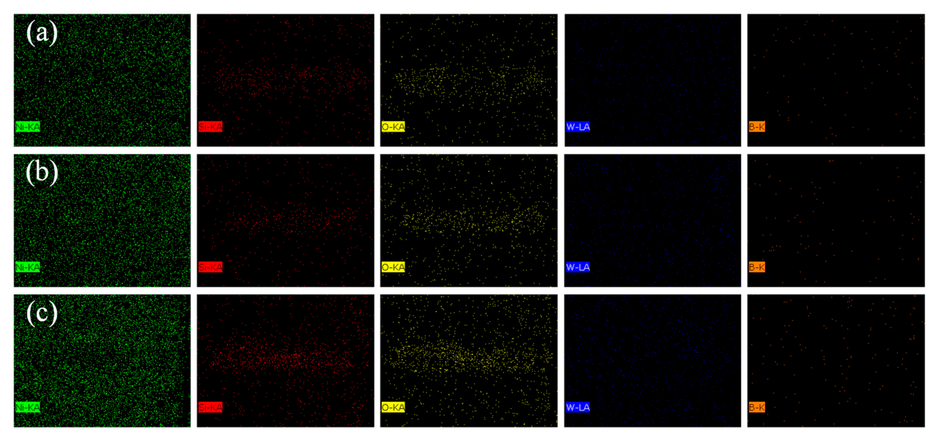
Table 7 summarizes the major elemental contents in different regions of the abrasion marks, labeled as regions 1, 2, and 3 in Figure 15, to further investigate the compositional changes occurring during wear. Figure 16 displays the EDS surface scan images of the wear scars. In each abrasion mark, the light-colored regions exhibit elevated concentrations of oxygen and silicon, with contents increasing as the reciprocating speed rises. This trend suggests that higher reciprocating speeds lead to increased surface temperatures, which in turn promote oxidation on the coating surface and contribute to oxidative wear.

Table 7.
Distribution of abrasion mark elements.
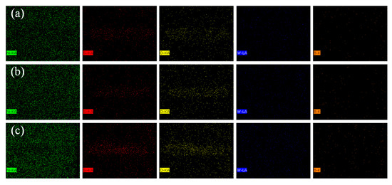
Figure 16.
Element distribution of coating wear (a) 200 times/min, (b) 400 times/min, (c) 600 times/min.
In addition, oxides are not only the byproducts of chemical wear, but also act as solid lubricants during the friction process. The oxide debris can form a protective film between the contact interfaces, thereby reducing shear stress and the abrasive cutting effect [37,38]. These findings suggest that the improved wear resistance of the coating is attributed to the synergistic effects of increased microhardness and the formation of protective surface oxides [39,40]. The observed wear behavior indicates that adhesive wear, oxidative wear, and abrasive wear are the dominant mechanisms during the sliding process.
4. Conclusions
In this study, the effects of four key process parameters—current density, coating temperature, ultrasonic power, and pulse current duty cycle—on the properties of Ni–P–WC–BN(h) nanocomposite coatings were systematically investigated using an orthogonal experimental design. Microhardness was selected as the evaluation index for optimization of the parameter combination. The main conclusions are as follows:
- Range analysis and ANOVA results showed that the influence of the four parameters on microhardness followed the order: current density (A) > duty cycle (D) > ultrasonic power (C) > temperature (B). The optimal parameter combination was determined to be A3B3C1D2, corresponding to a current density of 3 A·dm−2, a bath temperature of 55 °C, an ultrasonic power of 210 W, and a pulse duty cycle of 0.7. Under these conditions, the coating exhibited improved deposition quality, structural uniformity, and overall performance.
- The microhardness of the Ni–P–WC–BN(h) coating prepared under the optimal parameters reached 1244.3 HV1, which is approximately twice that of the 20CrMnTi substrate, indicating a significant improvement in mechanical strength.
- Tribological performance tests were conducted under a constant friction load of 320 g at reciprocating speeds of 200, 400, and 600 times/min. With increasing reciprocating speed, the COF increased, and the concentrations of O and Si elements in the wear track region also rose, indicating intensified oxidative processes. These results suggest that the predominant wear mechanisms involve abrasive wear, oxidative wear, and adhesive wear.
This study mainly focused on the microstructural and tribological analysis of the composite coating on flat substrates. To further explore engineering application potential, future research will consider applying the composite coating to typical mechanical components such as gears and shafts. Given the more complex service conditions in real applications, subsequent work will involve electroplating experiments on gears or shafts, accompanied by friction and wear performance testing under various working conditions. This will help verify the feasibility and stability of the coating in actual mechanical transmission systems.
Author Contributions
Conceptualization, Y.L. (Yingyue Li); methodology, Z.L.; validation, Y.L. (Yingyue Li), Z.L. and Y.L. (Yana Li); formal analysis, Y.L. (Yingyue Li); investigation, Y.L. (Yingyue Li); resources, J.L.; data curation, Y.L. (Yana Li); writing—original draft preparation, Y.L. (Yingyue Li); writing—review and editing, J.L. and Z.L.; visualization, Y.L. (Yana Li); supervision, J.L.; project administration, J.L.; funding acquisition, J.L. All authors have read and agreed to the published version of the manuscript.
Funding
This research was funded by the Student Research Training Program, grant number 864017.
Data Availability Statement
The original contributions presented in this study are included in the article. Further inquiries can be directed to the corresponding authors.
Conflicts of Interest
The authors declare no conflicts of interest.
References
- Yu, H.; Guo, Q.; Wang, C.; Cao, G.; Liu, Y. Preparation and performance of PANI/CNTs composite coating on 316 stainless steel bipolar plates by pulsed electrodeposition. Prog. Org. Coat. 2023, 182, 107611. [Google Scholar] [CrossRef]
- Kang, M.; Zhang, Y.; Li, H.Z. Study on the Performances of Ni-Co-P/BN(h)Nanocomposite Coatings Made by Jet Electro-deposition. Procedia CIRP 2018, 68, 221–226. [Google Scholar] [CrossRef]
- Zhou, J.; Jin, S.; Wu, R.; Ma, X.; Pang, M.; Yu, Z.; Wang, G.; Zhang, J.; Krit, B.; Betsofen, S.; et al. Enhancing tribological performance of micro-arc oxidation coatings on Mg-Li alloy with h-BN incorporation. Ceram. Int. 2025, 51, 13760–13771. [Google Scholar] [CrossRef]
- Kul, M.; Oskay, K.O.; Erden, F.; Akça, E.; Katırcı, R.; Köksaı, E.; Akıncı, E. Effect of Process Parameters on the Electrodeposition of Zinc on 1010 Steel: Central Composite Design Optimization. Int. J. Electrochem. Sci. 2020, 15, 9779–9795. [Google Scholar] [CrossRef]
- Zhang, W.; Xia, W.; Li, B.; Li, M.; Hong, M.; Zhang, Z. Influences of Co and process parameters on structure and corrosion properties of nanocrystalline Ni-W-Co ternary alloy film fabricated by electrodeposition at low current density. Surf. Coat. Technol. 2022, 439, 128457. [Google Scholar] [CrossRef]
- Liu, N.N.; Wu, M.H.; Li, Z. Optimization of Process Parameters of Ni-TiN-CeO2 Binary Nanocomposite Coatings by Ul-trasound-pulse Electrodeposition. In Advanced Materials and Process Technology, PTS 1–3, Proceedings of the 2nd International Conference on Advanced Design and Manufacturing Engineering (ADME 2012), Taiyuan, China, 16–18 August 2012; Liu, X., Bai, Z., Shuang, Y., Zhou, C., Shao, J., Eds.; Trans Tech Publications Ltd.: Wollerau, Switzerland, 2012; pp. 1331–1335. [Google Scholar] [CrossRef]
- Pan, M.-Q.; Chi, G.-X.; Wei, D.-B.; DI, S.-C. Influence of processing parameters on coating surface roughness of aluminum alloy. Trans. Nonferrous Met. Soc. China 2009, 19, s392–s397. [Google Scholar] [CrossRef]
- Zhang, Z.; Dai, L.; Yin, Y.; Xu, Z.; Lv, Y.; Liao, Z.; Wei, G.; Zhong, F.; Yuan, M. Electrodeposition and wear behavior of NiCoW ternary alloy coatings reinforced by Al2O3 nanoparticles: Influence of current density and electrolyte composition. Surf. Coat. Technol. 2021, 431, 128030. [Google Scholar] [CrossRef]
- Barut, U.; Karslioglu, R. Influence of current type on tribological and corrosion properties of nickel boron coatings produced by electrodeposition. Met. Mater. 2019, 57, 167–175. [Google Scholar] [CrossRef]
- Aliyu, I.K.; Azam, M.U.; Lawal, D.U.; Samad, M.A. Optimization of SiC Concentration and Process Parameters for a Wear-Resistant UHMWPE Nancocomposite. Arab. J. Sci. Eng. 2020, 45, 849–860. [Google Scholar] [CrossRef]
- Doan, T.V.; Dobrocký, D.; Pokorny, Z.; Kusmic, D.; Nguyen, V.T. Effect Of Plasma Nitriding On Mechanical And Tribological Properties of 42CrMo4 Steel. In Proceedings of the 17th International Conference on Advanced Batteries, Accumulators and Fuel Cells (ABAF 2016), Brno, Czech Republic, 28–31 August 2016; pp. 231–238. [Google Scholar]
- Wu, Y.; Zhang, Z.; Sun, S.; Zhang, J.; Yang, S.; Xu, K.; Zhu, H.; Liu, Y. A novel electrochemical deposited Fe Ni coating designed by laser-induced periodic current density: Effect of microstructure on microhardness and wear resistance improvement. Surf. Coat. Technol. 2023, 468, 129785. [Google Scholar] [CrossRef]
- Liu, Z.; Zhang, Q.; Zhang, X.; Yu, Z.; Zhang, X.; Mao, Q.; Nie, J.; Zhao, Y. Electrodeposition of nanocrystalline Ni and NiCr alloy coatings: Effects of Cr content on microhardness and wear resistance improvement. J. Mater. Res. Technol. 2024, 30, 3584–3593. [Google Scholar] [CrossRef]
- Li, Y.; Zheng, L.; Xu, X.; Zhang, Y.; Zhang, M.; Liu, M. Effect of current density on properties of Ni–P-Al2O3-PTFE nanocomposite coatings by jet electrodeposition. Int. J. Adv. Manuf. Technol. 2023, 125, 5743–5755. [Google Scholar] [CrossRef]
- Guo, C.; Zuo, Y.; Zhao, X.; Zhao, J.; Xiong, J. The effects of electrodeposition current density on properties of Ni–CNTs composite coatings. Surf. Coat. Technol. 2008, 202, 3246–3250. [Google Scholar] [CrossRef]
- Zhan, K.; Li, F.; Liu, J.; Cao, J.; Wang, Z.; Zhao, B. Preparation and mechanism of Cu-GO laminated composite films with high thermal conductivity by intermediate nickel and silver layers via electrodeposition and ultrasonic spraying method. Surf. Coat. Technol. 2023, 472, 129960. [Google Scholar] [CrossRef]
- Zhang, W.; Li, B. Influence of Electrodeposition Conditions on the Microstructure and Hardness of Ni-B/SiC Nanocom-posite Coatings. Int. J. Electrochem. Sci. 2018, 13, 3486–3500. [Google Scholar] [CrossRef]
- Das, M.K.; Urumarudappa, S.K.J.; Kamal, S.; Widiadita, Y.; Mahamud, A.; Saito, T.I.; Bovornratanaraks, T. Effect of Pulse Electrodeposition Parameters on the Microstructure and Mechanical Properties of Ni–W/B Nanocomposite Coatings. Nanomaterials 2022, 12, 1871. [Google Scholar] [CrossRef]
- Xu, Y.; Gao, Y.; Fan, M.; Lu, X.; Chen, Y.; Zhao, Q. Preparation and investigation of pulse co-deposited duplex nanoparticles reinforced Ni-Mo coatings under different electrodeposition parameters. Ceram. Int. 2022, 48, 29629–29640. [Google Scholar] [CrossRef]
- Kim, S.K.; Yoo, H.J. Formation of bilayer Ni–SiC composite coatings by electrodeposition. Surf. Coat. Technol. 1998, 108–109, 564–569. [Google Scholar] [CrossRef]
- Shen, Y.; Perepezko, J. Al-based amorphous alloys: Glass-forming ability, crystallization behavior and effects of minor alloying additions. J. Alloys Compd. 2017, 707, 3–11. [Google Scholar] [CrossRef]
- Biesinger, M.C.; Payne, B.P.; Grosvenor, A.P.; Lau, L.W.M.; Gerson, A.R.; Smart, R.S.C. Resolving surface chemical states in XPS analysis of first row transition metals, oxides and hydroxides: Cr, Mn, Fe, Co and Ni. Appl. Surf. Sci. 2011, 257, 2717–2730. [Google Scholar] [CrossRef]
- Yin, D.; Peng, X.; Qin, Y.; Feng, J.; Wang, Z. Quantifying adhesion energy of mechanical coatings at atomistic scale. Appl. Surf. Sci. 2011, 258, 1451–1455. [Google Scholar] [CrossRef]
- Fan, H.; Zhao, Y.; Jiang, J.; Wang, S.; Shan, W.; Li, Z. Effect of the Pulse Duty Cycle on the Microstructure and Properties of a Jet Electrodeposited Nanocrystalline Copper Coating. Mater. Trans. 2020, 61, 795–800. [Google Scholar] [CrossRef]
- Singhal, S.K.; Srivastava, A.K.; Pant, R.P.; Halder, S.K.; Singh, B.P.; Gupta, A.K. Synthesis of boron nitride nanotubes employing mechanothermal process and its characterization. J. Mater. Sci. 2008, 43, 5243–5250. [Google Scholar] [CrossRef]
- Singhal, S.K.; Srivastava, A.K.; Mathur, R.B. Growth of Boron Nitride Nanotubes Having Large Surface Area Using Mechanothermal Process. World J. Nano Sci. Eng. 2011, 01, 119–128. [Google Scholar] [CrossRef][Green Version]
- Ren, A.; Kang, M.; Fu, X.; Zhang, F.; Yang, W.; Pan, T. Preparation of Ni–B composite coating doped with hydrothermally modified synthetic WC@MoS2 powders via ultrasonic-assisted jet electrodeposition for corrosion protection. Surf. Interfaces 2024, 44, 103674. [Google Scholar] [CrossRef]
- Gao, M.; Pei, Z.; Song, G.; Liu, Z.; Gu, W.; Gong, J. Wear resistance of electro-brush plated Ni/diamond nanocomposite coatings. Diam. Relat. Mater. 2025, 153, 111992. [Google Scholar] [CrossRef]
- Xu, Y.; Liang, B.; Gao, Y.; Zou, J.; Hua, R.; Sun, Y.; Chen, Y.; Zhao, Q. Pulse electrodeposition of a duplex-layer structured composite nickel-based coating with improved corrosion and abrasion resistance. Ceram. Int. 2024, 50, 10515–10524. [Google Scholar] [CrossRef]
- Huang, P.-C.; Cheng, C.-H. Preparation and tribocorrosion behavior of electrodeposited Ni–W/SiC composite coatings. Wear 2024, 558–559, 205571. [Google Scholar] [CrossRef]
- Cheng, X.; He, Y.; Song, R.; Li, H.; Liu, B.; Zhou, H.; Yan, L. Study of mechanical character and corrosion properties of La2O3 nanoparticle reinforced Ni-W composite coatings. Colloids Surf. A Physicochem. Eng. Asp. 2022, 652, 129799. [Google Scholar] [CrossRef]
- Shaik, S.; Basu, A. Effect of multiple dissimilar nanoparticles in Ni–W alloy matrix composite coating and evaluation of surface-mechanical, corrosion, and hydrophobic properties. Mater. Chem. Phys. 2022, 278, 125585. [Google Scholar] [CrossRef]
- Zhang, L.; Shang, C.; Wang, F.; Zheng, T.; Nie, C.; Qiao, Y.; Sun, G.; Wang, X.; Liu, Y. The wear behavior and corrosion resistance properties of Ni-based composite coatings modified with CeO2 and MoS2 nanoparticles. Colloids Surf. A Physicochem. Eng. Asp. 2025, 719, 137017. [Google Scholar] [CrossRef]
- Moreno, M.; Andersson, J.M.; M’SAoubi, R.; Kryzhanivskyy, V.; Johansson-Jöesaar, M.P.; Johnson, L.J.; Odén, M.; Rogström, L. Adhesive wear of TiAlN coatings during low speed turning of stainless steel 316L. Wear 2023, 524–525, 204838. [Google Scholar] [CrossRef]
- Zhang, Y.; Han, J.; Cao, S.; Song, X.; Yan, X.; Nie, F.; Peng, Z. Wear behavior of coated cermet/carbide tools during high-speed turning of 18CrNiMo7-6 steel and its associated surface integrity evaluations. Wear 2025, 576–577, 206121. [Google Scholar] [CrossRef]
- Xu, Y.; Zheng, X.; Hu, X.; Yin, Y.; Lei, T. Preparation of the electroless Ni–P and Ni–Cu–P coatings on engine cylinder and their tribological behaviors under bio-oil lubricated conditions. Surf. Coat. Technol. 2014, 258, 790–796. [Google Scholar] [CrossRef]
- Ilie, F.; Ipate, G.; Manaila, F.C. Tribological Properties Study of Solid Lubrication with TiO2 Powder Particles. Materials 2022, 15, 7145. [Google Scholar] [CrossRef]
- Uniyal, P.; Gaur, P.; Yadav, J.; Khan, T.; Ahmed, O.S. A Review on the Effect of Metal Oxide Nanoparticles on Tribological Properties of Biolubricants. ACS Omega 2024, 9, 12436–12456. [Google Scholar] [CrossRef]
- Chen, Y.; Li, H.; Li, S.-E.; Sun, G.-X.; Zhao, L.; Hu, C.-Q.; Zhang, W.; Tong, G.-D.; Chen, X.-G.; Han, S.; et al. Effects of nanostructuring on mechanical and tribological behaviors of FeCoNi medium-entropy alloy. Trans. Nonferrous Met. Soc. China 2024, 34, 3963–3977. [Google Scholar] [CrossRef]
- Wang, S.; Pang, X.; Xu, Y.; Lu, H.; Jiang, P.; Yang, J.; Liao, Z. Microstructure, mechanical and tribological properties of in situ MoB reinforced Cu-Al matrix composites. Tribol. Int. 2023, 177, 107941. [Google Scholar] [CrossRef]
Disclaimer/Publisher’s Note: The statements, opinions and data contained in all publications are solely those of the individual author(s) and contributor(s) and not of MDPI and/or the editor(s). MDPI and/or the editor(s) disclaim responsibility for any injury to people or property resulting from any ideas, methods, instructions or products referred to in the content. |
© 2025 by the authors. Licensee MDPI, Basel, Switzerland. This article is an open access article distributed under the terms and conditions of the Creative Commons Attribution (CC BY) license (https://creativecommons.org/licenses/by/4.0/).


