Article

Study on Cutting Performance and Wear Resistance of Biomimetic Micro-Textured Composite Cutting Tools

1
School of Mechanical and Electronic Engineering, Qiqihar University, Qiqihar 161006, China
2
Key Laboratory of Advanced Manufacturing and Intelligent Technology, Ministry of Education, Harbin University of Science and Technology, Harbin 150080, China
3
QiQiHar Heavy CNC Equipment Co., Ltd., Qiqihar 161005, China
4
The Engineering Technology Research Center for Precision Manufacturing Equipment and Industrial Perception of Heilongjiang Province, Qiqihar 161006, China
5
The Collaborative Innovation Center for Intelligent Manufacturing Equipment Industrialization, Qiqihar 161006, China
6
School of Mechatronics Engineering, Harbin Institute of Technology, Harbin 150001, China
*
Author to whom correspondence should be addressed.
Metals 2025, 15(7), 697; https://doi.org/10.3390/met15070697
Submission received: 28 May 2025 / Revised: 17 June 2025 / Accepted: 20 June 2025 / Published: 23 June 2025

Abstract

During the dry machining of 6061 aluminum alloy, cemented carbide tools often suffer from severe wear and built-up edge (BUE) formation, which significantly shortens tool life. Inspired by the non-smooth surface structure of dung beetles, this study proposes an elliptical dimple–groove composite bionic micro-texture, applied to the rake face of cemented carbide tools to enhance their cutting performance. Four types of tools with different surface textures were designed: non-textured (NT), single-groove texture (PT), circular dimple–groove composite texture (AKGC), and elliptical dimple–groove composite texture (TYGC). The cutting performance of these tools was analyzed through three-dimensional finite element simulations using the Deform-3D (version 11.0, Scientific Forming Technologies Corporation, Columbus, OH, USA) software program. The results showed that, compared to the NT tool, the TYGC tool exhibited the best performance, with a reduction in the main cutting force of approximately 30%, decreased tool wear, and significantly improved chip-breaking behavior. Based on the simulation results, a response surface model was constructed to optimize key texture parameters, and the optimal texture configuration was obtained. In addition, a theoretical model was developed to reveal the mechanism by which the micro-texture reduces interfacial friction and temperature rises by shortening the effective contact length. To verify the accuracy of the simulation and theoretical analysis, cutting experiments were further conducted. The experimental results were consistent with the simulation trends, and the TYGC tool demonstrated superior performance in terms of cutting force reduction, smaller adhesion area, and more stable cutting behavior, validating both the simulation model and the proposed texture design. This study provides a theoretical foundation for the structural optimization of bionic micro-textured cutting tools and offers an in-depth exploration of their friction-reducing and wear-resistant mechanisms, showing promising potential for practical engineering applications.

1. Introduction

The 6061 aluminum alloy has been widely used in industrial manufacturing and production due to its excellent processing performance, outstanding corrosion resistance, and high strength and toughness [1,2,3]. However, during the aluminum alloy cutting process, significant cutting heat is generated, which leads to problems such as tool adhesion, an accelerated tool wear rate, and tool bond damage, seriously affecting tool service life. Scholars worldwide have found that introducing micro-texture technology into the field of tool design based on bionics theory can effectively reduce cutting forces, lower cutting temperatures, and suppress tool adhesion damage. Liang Zhiqiang et al. [4] used a micro-grinding method to prepare transverse, longitudinal, and intersecting micro-textures with different structural parameters on the front cutting surface of hard-alloy cutting tools. Through AL6061 cutting tests and finite element cutting simulation, the influence of micro-textures on the cutting temperature and tool wear of hard-alloy cutting tools was studied. Research has found that the surface micro-texture can effectively reduce the adhesive wear of the tool’s front cutting surface, and transverse textured tools have the best anti-friction and anti-adhesion effect. Moreover, using smaller groove spacing is more conducive to reducing the adhesive wear of the tool. Xu Minggang et al. [5] investigated the effect of micro-texture placement on the cutting performance of cutting tools. The research results showed that after the placement of groove micro-textures, the contact area between friction pairs was reduced, and the instantaneous high-temperature phenomenon was alleviated under the dual action of cutting fluid. The friction and wear condition of the tool was greatly improved, and the service life was extended. Musavi S H et al. [6] used laser processing to prepare grooves parallel to the cutting edge at different distances on the front cutting surface of the tool, and studied the cutting performance of the tool under micro-lubrication and drying conditions; the research results indicate that under those conditions, groove micro-textured tool cutting performance exceeds that of non-textured tools, and the tool wear and surface roughness under micro-lubrication machining conditions are better than those of dry machining. Robert B et al. [7] used laser technology to machine groove textures on the inclined side of hard-alloy cutting tools, and conducted turning experiments on Al 6061 under lubrication conditions using groove texture tools and non-textured tools. The research results show that groove-textured tools reduce cutting force by 17% compared to non-textured tools, while groove-textured tools produce thinner chips and reduce the surface roughness of aluminum workpieces by 31%. Sugihara T. et al. [8] studied two types of micro-textures (pits and grooves) on hard-alloy cutting tools and explored their effects on tool wear during cutting. Research has found that micro-textured pits exhibit better performance in resisting tool adhesion wear. Sun X et al. [9] used femtosecond laser technology to prepare five different sizes of groove textures on the front cutting surface of hard-alloy cutting tools to address the issue of tool bond damage during aluminum alloy processing. In addition, dry cutting experiments and a simulation analysis were conducted on cutting tools with different textures. The research results indicate that within a specific size range, groove textures can effectively improve the bonding damage problem of workpieces on the front cutting surface of the tool. Wang et al. [10] investigated the application of micro-grooves on carbide inserts and reported a reduction in tool wear and cutting force during the dry turning of aluminum alloys. Javidikia et al. [11] investigated the effects of turning environments and machining parameters on the surface integrity of AL6061-T6, highlighting the importance of process optimization in aluminum alloy machining. Singh et al. [12] reviewed various fabrication and reinforcement strategies for Al-MMCs, emphasizing their increasing application potential and the urgent need for effective machining solutions. Jamil et al. [13] conducted a detailed investigation into the influence of cutting parameters on surface quality in the dry turning of AA7075-T6 using ZrCN-coated WC inserts, highlighting the critical role of cutting conditions on surface roughness and tool life.
Meanwhile, numerous scholars both domestically and internationally have conducted extensive research on the design and cutting performance of micro-textured cutting tools. Feng et al. [14] conducted a study on the cutting performance of GH4169 using a combination of numerical simulation and experimental research on pit-type micro-textures machined on the front cutting surface of cutting tools using laser processing methods. The study showed that pit-type micro-textures have lower cutting forces. Fan et al. [15] reported that, compared with conventional tools, micro-textured tools produce chips with smaller curling radii and more stable morphologies, among which transverse groove textures exhibit the best chip-breaking performance. Li Binbin et al. [16] used finite element simulation software to conduct simulation experiments on the cutting of nickel-based alloys with sinusoidal micro-textured cutting tools. The research results showed that surface sinusoidal micro-textured cutting tools performed better than non-textured cutting tools in terms of cutting force, tool temperature field, and chip breaking ability. Le Qizhong et al. [17] used finite element simulation and cutting experiments to study the influence of straight textured grooves on the cutting force and cutting temperature of nickel-based high-temperature alloy GH4169 during the cutting process. The simulation results showed that the front face texture could reduce the cutting force and cutting temperature of the tool; meanwhile, cutting tests showed that textured tools parallel to the cutting edge have the best wear resistance and cutting life. The working life of textured cutting tools has thus been increased by 66% compared to non-textured cutting tools (7%). Yu Q X et al. [18] designed a convex volcano-shaped composite textured cutting tool by referring to the excellent cutting ability of bamboo mouse teeth. Compared with traditional cutting tools, this tool not only exhibits a better cutting performance, but also significantly improves its anti-adhesion and is suitable for dry cutting conditions. Fu Yonghong and Li Yudi et al. [19,20] found that composite micro-textures exhibit a better cutting performance than single-type micro-textures, especially in significantly enhancing anti-bonding performance. Zhang [21] and Tu [22], respectively, investigated the cutting performance of single-type micro-textured tools (micro-dimples) under wet and dry cutting conditions, and compared with non-textured tools, the cutting force was reduced by 21.2% and 15.85%, respectively.
A comprehensive review of the existing literature reveals that most current studies focus primarily on single-type micro-textures, with relatively limited exploration of composite micro-texture designs. This study therefore proposes a novel elliptical dimple–groove composite biomimetic micro-texture inspired by the non-smooth surface structures of dung beetles, and applies it to the rake face of cemented carbide cutting tools. Using a research approach that integrates finite element simulation with previously reported experimental results, the cutting performance of various textured tools was evaluated in terms of cutting force, temperature, and wear depth. The optimal texture exhibiting superior friction reduction and wear resistance was identified, and the underlying synergistic mechanisms of the elliptical dimple–groove structure were revealed and validated through simulation. Furthermore, the response surface methodology was employed to optimize the multi-parameter design of the selected texture. The results demonstrated that the proposed composite biomimetic texture significantly enhances cutting performance compared to other textures. This research provides valuable theoretical guidance for tool parameter optimization in practical machining applications.

2. Materials and Methods

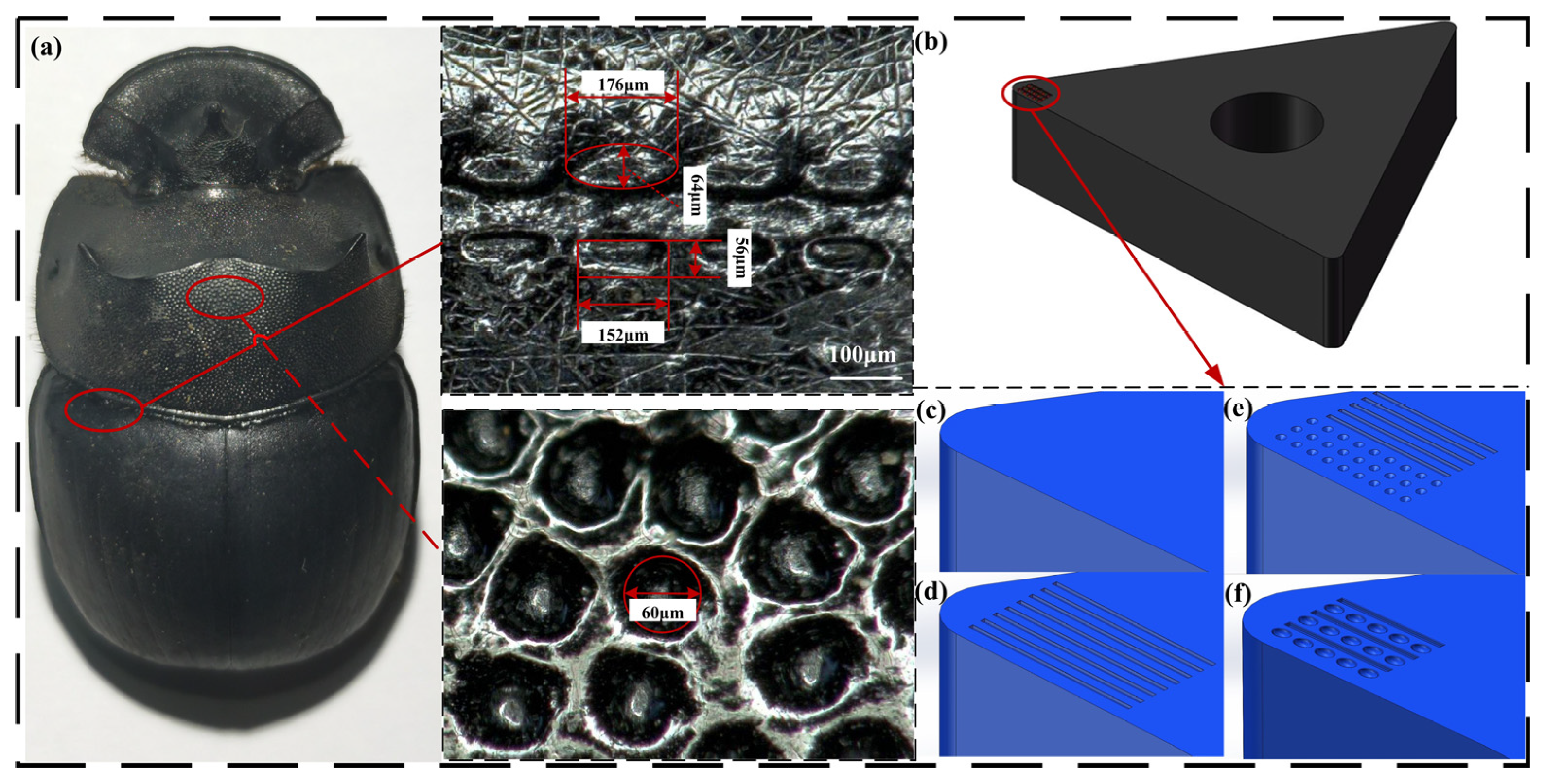
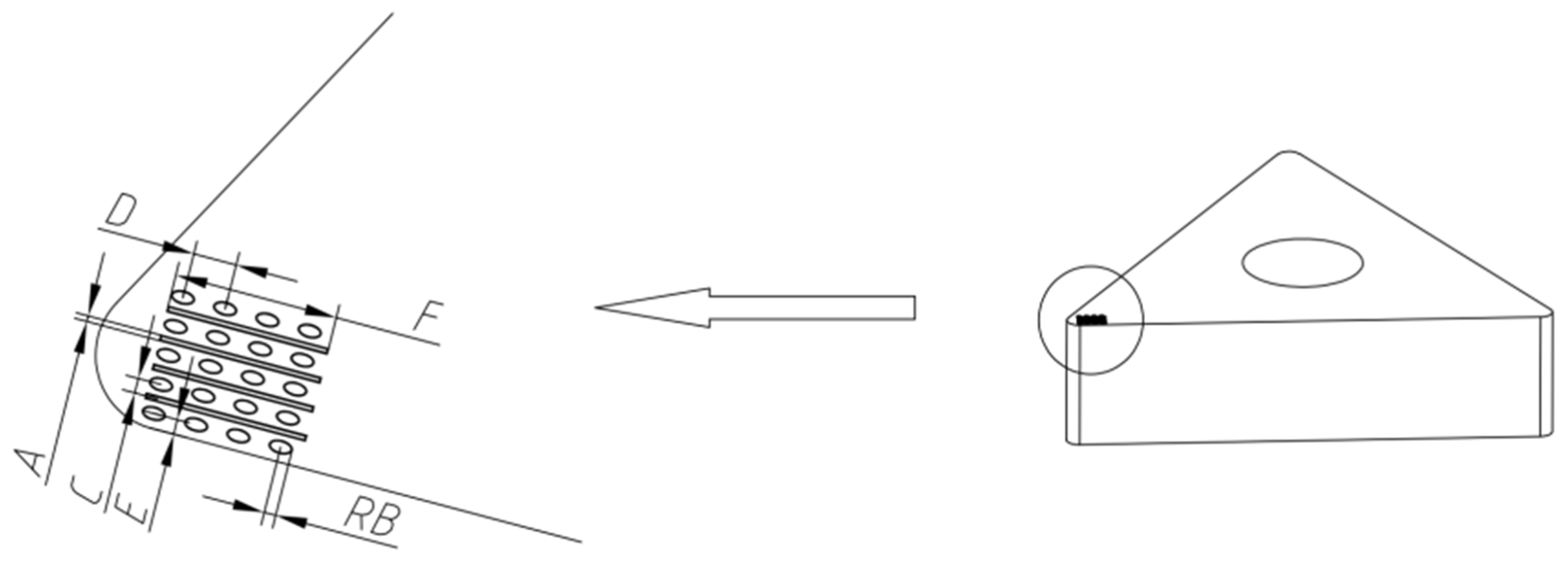
2.1. Selection of Bionic Design Prototype and Tool Modeling for Combined Micro-Textures

Studies have shown that dung beetles exhibit strong anti-adhesive behavior during soil displacement, primarily due to the unique microstructures on their body surface. These structures reduce the effective contact area and trap air, thereby lowering interfacial negative pressure and enhancing drag-reducing and anti-adhesive performance. In this study, the dimpled surface morphology on the dorsal side of the dung beetle was selected as the bionic design prototype. Microscopic observations revealed that its surface is densely covered with various microstructures, including circular, grooved, and elliptical dimples. Measurements indicated that the depth of the dimples on the beetle surface ranges from 10 to 20 µm, with lengths of 100 to 200 µm and widths of 70 to 100 µm. Based on these characteristics, the corresponding features were incorporated into the design of bionic micro-textured cutting tools. The observed surface morphology is shown in Figure 1a. Four types of tools were designed accordingly: non-textured (NT), groove-textured (PT), circular dimple–groove hybrid texture (AKGC), and elliptical dimple–groove hybrid texture (TYGC). Their corresponding 3D models are illustrated in Figure 1c–f.
To improve the simulation efficiency and computational accuracy, the tool geometry was appropriately simplified by extracting only the cutting edge section in contact with the workpiece. The Deform-3D (version 11.0, Scientific Forming Technologies Corporation, Columbus, OH, USA) software program was employed to simulate the cutting performance of the micro-textured tools. The tool material is a WC-based hard alloy, as shown in Figure 1b, with dimensions of 16 × 16 × 4 mm and a tool tip radius of 0.4 mm.

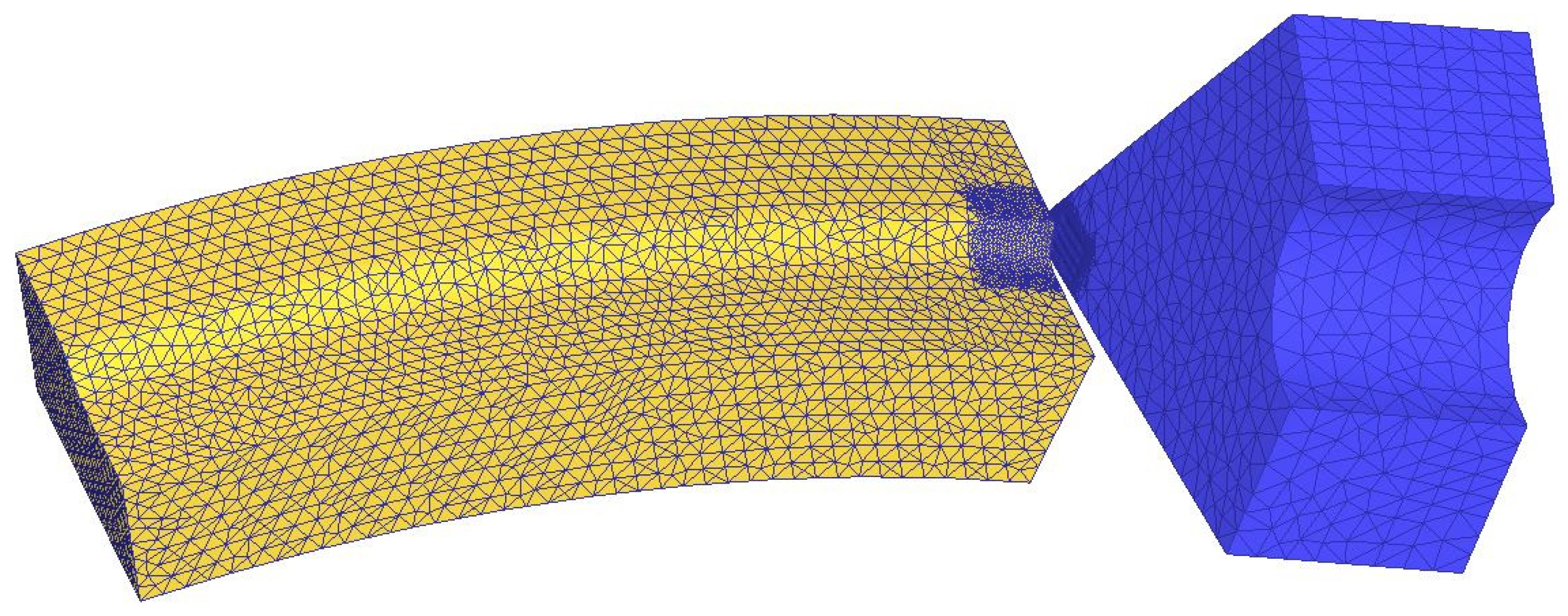
2.2. Cutting Simulation Modeling and Definition of Key Physical Parameters

Numerous studies by domestic and international scholars have demonstrated that finite element cutting simulation is an important method for investigating and addressing machining-related problems. In this study, the cutting performance of different micro-textured tools was thus analyzed using the DEFORM-3D (version 11.0, Scientific Forming Technologies Corporation, Columbus, OH, USA) finite element simulation software program. The specific pre-processing steps for the cutting simulation are as follows: The tool was modeled as a rigid body, with cemented carbide selected as the tool material. The workpiece was defined as a plastic body, using 6061 aluminum alloy (Northeast Light Alloy Co., Ltd., Harbin, China). The workpiece geometry included an arc radius of 30 mm, and the cutting length corresponded to the arc length of a 30° central angle. An orthogonal cutting model was adopted, with the tool cutting perpendicularly to the workpiece. The cutting speed was set to v = 120 m/min, the depth of cut was 0.5 mm, and the feed rate was 0.3 mm/rev. Dry cutting conditions were assumed at room temperature (20 °C). The friction between the tool and workpiece was defined as shear friction, with a friction coefficient of 0.6. A natural convection boundary condition was applied to the outer surface of the tool (in contact with air), with a heat transfer coefficient of 20 W/(m2·K), to simulate the heat dissipation from the tool surface during dry cutting. To better capture the simulation results in the primary cutting zone, the relative remeshing technique was employed. In addition, the mesh was locally refined in the contact region between the texture and the workpiece. The pre-processing setup is shown in Figure 2.
We selected tungsten carbide/cobalt (WC/Co) hard alloy as the tool material. The chemical structure and physical and mechanical properties of the cutting tools are shown in Table 1 [23]. The workpiece material is 6061 aluminum alloy (Northeast Light Alloy Co., Ltd., Harbin, China), and its mechanical properties are shown in Table 2 [24].
During metal cutting, the material undergoes both elastic and plastic deformation, and under the interaction of work hardening and thermal softening, the material properties undergo changes. These changes cause the boundary state of the material to exhibit highly nonlinear characteristics, including complex phenomena such as plastic yield, flow, hardening, extrusion, and friction. The simulation accuracy therefore largely depends on the selection of material constitutive models. The ideal improved J-C model using rigid plastic materials [25] is used to simulate accurate cutting behavior. The parameter values in the J-C constitutive model of 6061 aluminum alloy are shown in Table 3, and their expressions are as given below:
σ = A + B ε ¯ n 1 + C l n ε ¯ · 1 T * m
In the formula, σ is the Mises flow stress; ε ¯ is the equivalent plastic strain; ε ¯ · is the equivalent plastic strain rate; A, B, C, m, and n are related to the properties of the material itself. T * is the relative temperature, and its expression is
T * = T T r o o m T m e l t T r o o m
Table 3. J-C model parameters of 6061 aluminum alloy Adapted from Ref. [25].
MaterialA [MPa]B [MPa] mCnTmelt
6061 aluminum alloy3141141.340.0020.42610
A physical criterion and a geometric criterion have been created here to describe the separation of chips and workpieces. The Cockrow–Latham (C-L) model [26] considers the physical phenomenon of separation between nodes and workpiece materials. This study therefore adopts the Cockrow–Latham fracture criterion as the criterion for chip separation, which is described as follows:
0 ε f ¯ σ * d ε ¯ = C
In the formula, ε f represents the total strain at which the material fractures at high temperatures; σ * and ε ¯ are the maximum principal stress and equivalent strain, respectively; and C is the critical value for material separation, taken as 500.
In the formula, w is the cumulative wear amount (mm); P is the work pressure (Pa); T is the absolute temperature (°C); dt is the time increment (s); V is the relative speed of the tool (m/s); a is a constant, taking the empirical value a = 10−6; and b is a constant, taking the empirical value b = 850.

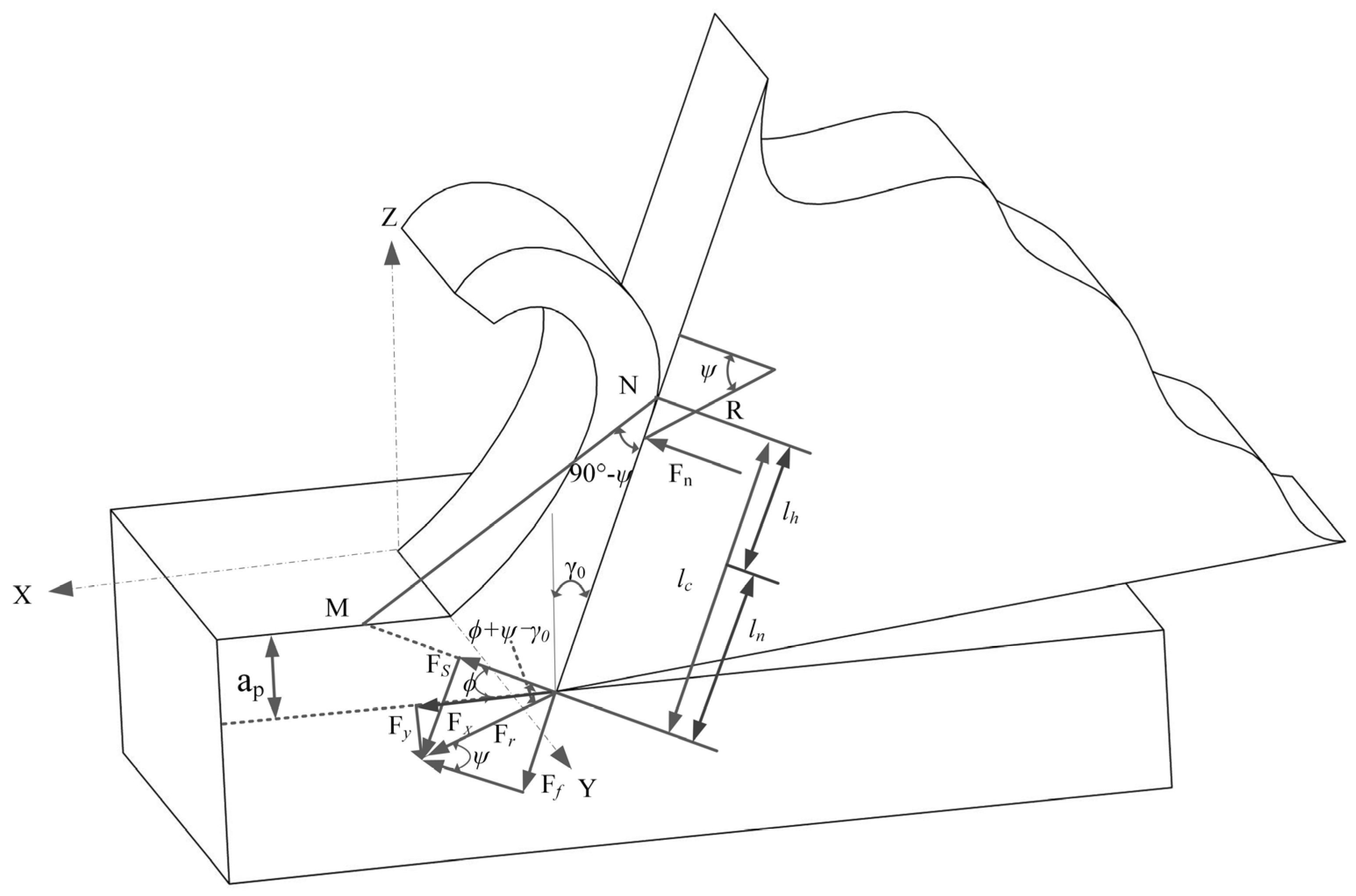
2.3. Force Analysis of the Contact Interface Between Cutting Tools and Chips

2.3.1. Force Analysis at the Tool–Chip Contact Interface

According to Zorve’s friction theory, the interactive chip contact interface can be divided into two areas, the adhesive friction area and the sliding friction area, as given in Figure 3. Assuming the contact length between the blade and chip is lc, this interval can be divided into the bonding zone ln and the sliding zone lh. The distribution forms of shear stress and normal stress in the bonding and sliding zones are different, and the normal stress gradually decreases in the blade–chip contact zone. The shear stress is equal to the shear yield strength of the material in the bonding zone, and gradually decreases in the sliding zone. The normal stress and shear stress are shown in Equations (5) and (6) [27].
Normal stress distribution is as follows:
σ ( D ) = σ 0 1 D l c k 0 D l c
In this formula, k is the attenuation coefficient (taking a value of 2 here), and D is the distance from a point in the tool chip contact area to the cutting edge.
Shear stress distribution is as follows:
τ ( D ) = τ W D < l n
τ D = μ σ 0 1 D l c k l n D l c
In this formula, τ W is the shear stress in the bonding zone, and µ is the friction coefficient in slip zone.
Normal stress at the interface of the tool chip contact Fn is given as follows:
F n = 0 l c σ 0 1 D l c k d D
Frictional force Ff on the contact surface of cutting chips is given as follows:
F f = A b τ W + l n l c μ σ 0 1 D l c A s d s
In this formula, Ab is the contact area of the bonding zone, and As is the sliding area contact area.
The contact interface between the textured cutting tool and the chip is given in Figure 4. Assuming the stress distribution at the texture is 0, the stress distribution at the non-textured tool remains unchanged, the distance between the tool tip and micro-texture at the bonding zone is D1, and the distance between the micro-texture in the sliding zone and the tool tip is D2, the normal stress and friction force at the tool chip contact interface are analyzed.
The normal stress and friction force at the interface between the textured cutting tool and the chip are as follows:
F n = 0 l f d x x 1 x 1 + w σ x d x x 2 x 2 + w σ x d x
F f = τ W A b w d + l n l c μ σ D A s d D D 2 D 2 + w μ σ x A s d D

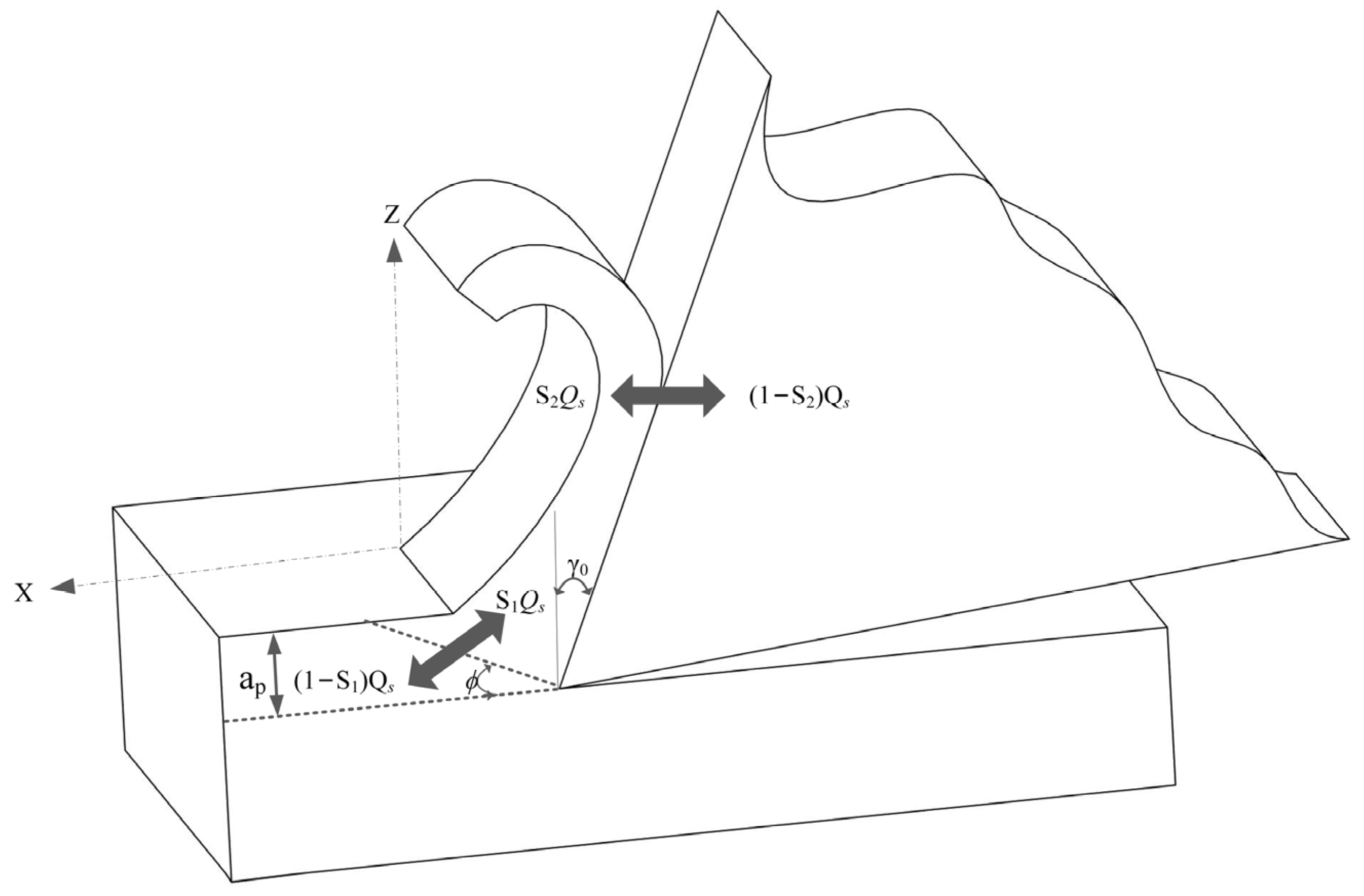
2.3.2. The Influence of Micro-Textured Cutting Tools on Cutting Temperature

In the metal cutting process, the generation of cutting heat mainly comes from two aspects, including the friction between the front cutting surface and the chip, the friction between the workpiece and the back cutting surface, and the work performed by the deformation of the chip’s domain. The high cutting temperature is due to the difficulty in discharging the generated cutting heat. In essence, the cutting temperature is the mean temperature at the point of contact between the tool and the chip, and may be estimated by summing the average temperature of the shear surface and the temperature resulting from the friction at the interface between the tool and the chip [27].
T t = T f + T s
In the formula, Tt is the average temperature of the blade–chip contact area, Tf is the friction temperature of blade–chip contact interface, and Ts is the average temperature of the shear surface.
The heat transfer of cutting heat during the cutting process is shown in Figure 5.
Assuming that the energy expended in the plastic deformation process is converted into heat, the heat generated per unit time and per unit area is Qs:
Q s = F s v s s i n φ a p a d
In the formula, vs is the shear speed, ap is the cutting thickness, and ad is the cutting width.
The average temperature Ts of chips on the cutting surface is calculated as follows:
T s = S 1 v s τ W C 1 ρ 1 v sin φ + T 0
In the formula, S1 is the fraction of heat generated by the shear surface flowing into the chips; C1 is the specific heat capacity of the average temperature of the workpiece material between T0 and Tj; ρ 1 is the density of the workpiece material; v is the cutting speed; τ W is the shear strength of workpiece material; and T0 is the environmental temperature.
As shown in Figure 3, the actual contact length between the blade and chip is
l a = l c n w
The average temperature Tf generated by friction on the blade–chip contact surface is calculated as follows:
T f = 0.754 S 2 τ ¯ q v l c n w k c 2 ρ 2 k 2
The average temperature Tt in the blade–chip contact area is calculated as follows:
T t = S 1 v s τ W C 1 ρ 1 v sin φ + T 0 + 0.754 S 2 τ ¯ q v l c n w k c 2 ρ 2 k 2
According to Equation (16), while keeping other parameters constant, the usual temperature in the knife chip contact area is directly proportional to the length of the knife chip contact. When the length of the knife chip contact decreases, the average temperature in the knife chip contact area will also decrease.

3. Result Analysis and Discussion

3.1. Scheme Optimization

3.1.1. Cutting Force

Cutting force, as a key index to measure the cutting performance of a tool, has a direct impact on the service life of the tool. Figure 6a shows the time-varying cutting force curves of different biomimetic microstructured cutting tools. It can be observed from the figure that with the increase in cutting steps, the cutting force initially shows a sharp upward trend, and with the increase in steps, the cutting force fluctuates in a certain range. The analysis shows that the main cutting force of the TYGC (elliptical groove staggered combined texture) tool is the lowest of the four groups of tools, being 30.18% lower than that of the NT (traditional non-textured) tool, 21.49% lower than that of the PT (single-groove texture) tool, and 25.52% lower than that of the AKGC (combined texture before and after the pit groove) tool. It is worth noting that the main cutting force of the TYGC tool changes most stably. This result shows that the introduction of micro-textures effectively reduces the actual contact area between the tool rake face and the workpiece, thus reducing the friction and power consumption between the tool and the workpiece. This reduces and stabilizes the cutting force. The combined bionic micro-texture exhibits a better cutting performance than the single texture.
To evaluate the influence of the constant friction coefficient assumption on the simulation results, a sensitivity analysis was conducted. The Coulomb friction coefficient (μ) was varied within the range of 0.2 to 0.6, and the cutting performance of four different tool types under various friction conditions was compared. As shown in Figure 6b, the main cutting force of all tool types increased with higher friction coefficients. However, the performance trends among different structures remained consistent—the TYGC tool consistently exhibited the lowest cutting force, while the NT (non-textured) tool showed the highest. These findings indicate that the model maintains good stability with respect to variations in friction parameters. Adopting a constant friction coefficient is a simplification, and it therefore has a minimal impact on the comparative conclusions between different tool structures, thereby supporting the reliability of the simulation results presented in this study.

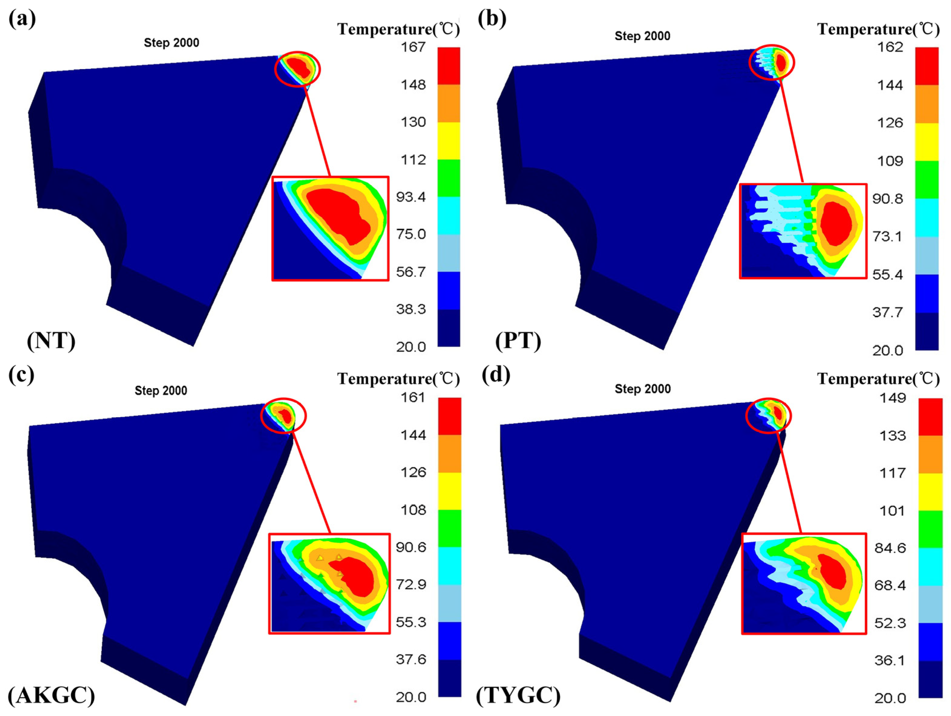
3.1.2. Cutting Temperature
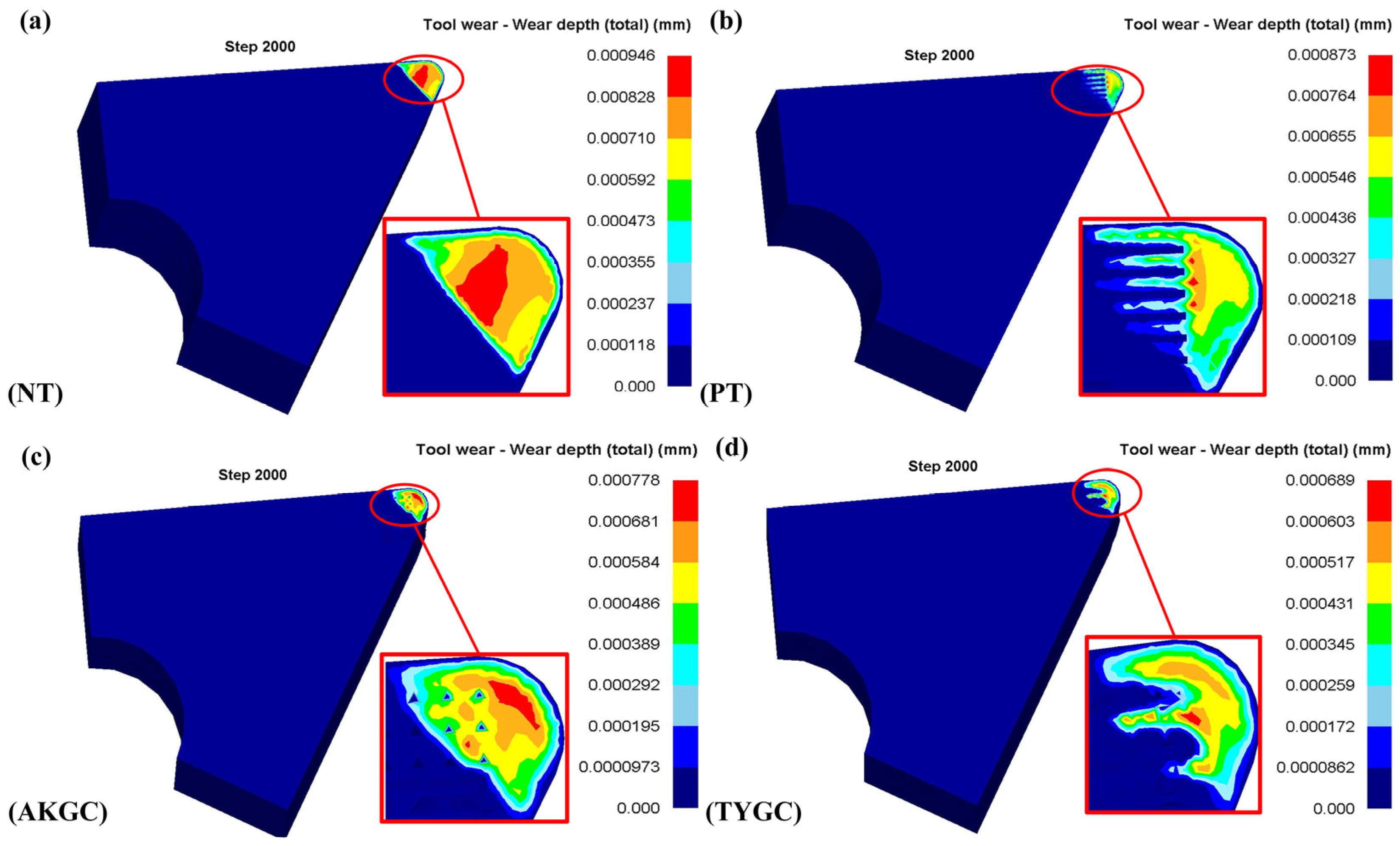
The cutting temperature on the rake face is a critical factor influencing tool wear and adhesive damage. As shown in Figure 7, the maximum temperature for all tool types is concentrated near the tool tip and rapidly decreases outward, forming a clear temperature gradient. In Figure 7a, the non-textured (NT) tool exhibits a large, concentrated high-temperature region, with a peak temperature reaching 167 °C, the highest among all four tools. In contrast, the textured tools in Figure 7b–d show reduced peak temperatures of 149 °C for TYGC (a reduction of 10.78%), 161 °C for AKGC (3.59% reduction), and 162 °C for GC (2.99% reduction), with the TYGC tool demonstrating the most significant cooling effect. This performance is attributed to the ability of micro-textures to dissipate the heat generated by friction and plastic deformation during cutting. The NT tool shows a clearly localized high-temperature zone, while the textured tools exhibit temperature distributions mainly around the textured regions, with lower internal temperatures—indicating superior thermal diffusion capabilities. The smallest high-temperature area observed in the TYGC tool further validates its excellent heat reduction performance. Previous studies have shown that surface textures not only reduce the actual contact area and friction between the rake face and the workpiece but also enhance convective heat dissipation through the air gaps introduced by the textures, thereby effectively lowering the cutting temperature.

3.1.3. Wear Degree

Figure 8 presents the distribution of cumulative wear depth on different tools during cutting simulation. As shown in Figure 8a, the non-textured (NT) tool exhibits the largest wear area. In contrast, the PT and AKGC tools show wear reductions of 7.72% and 17.6%, respectively. Figure 8d indicates that the TYGC tool demonstrates the best anti-wear performance, with a wear reduction of 27.1% compared to the NT tool. According to Equations (10) and (16), both cutting force and temperature are closely related to friction. The frictional force on the rake face is proportional to the actual contact area between the chip and the tool. As illustrated in the figure, the maximum wear depth of each tool is concentrated near the tool tip, which closely corresponds to the high-temperature regions shown in the temperature distributions, indicating that temperature significantly affects tool wear. Moreover, the NT tool experiences extensive wear, while the textured tools exhibit minimal wear in the micro-textured regions. Notably, the TYGC tool displays the least wear, highlighting the effectiveness of micro-textures in reducing the contact area and suppressing wear. These findings provide important guidance for extending tool life and optimizing cutting processes.

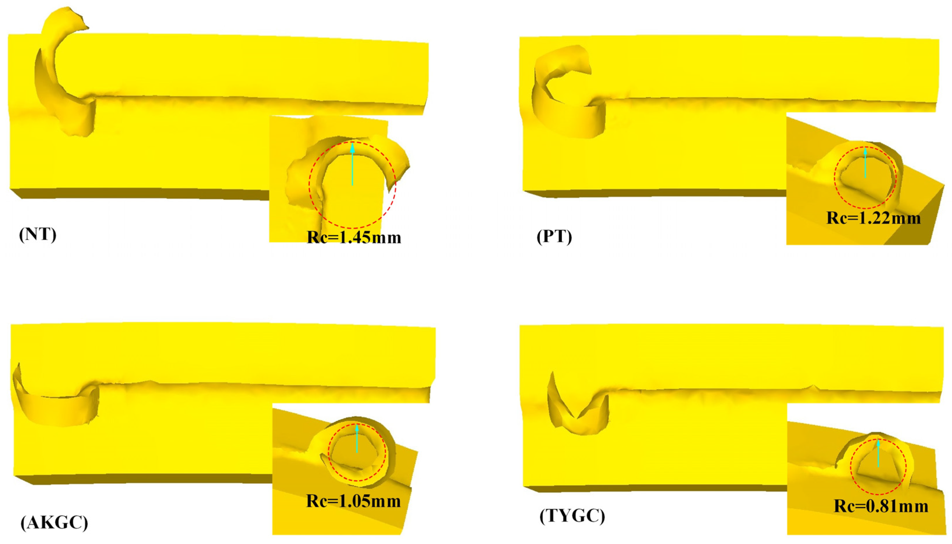
3.1.4. Chip Morphology and Fracture

Figure 9 shows the macroscopic morphology of chips from different biomimetic micro-textured cutting tools. From Figure 10, it can be observed that the chip curl radius generated by traditional textureless cutting tools (NT) is larger than that generated by other textures, and the chip morphology generated by textured cutting tools is spiral. Compared to other cutting tools, TYGC tools produce not only the smallest but also a very uniform chip curling radius during the cutting process, with the chip curl radius decreasing by 44.13% compared to the NT tool. This phenomenon can be attributed to the texture direction of TYGC cutting tools being parallel to the cutting edge, a design facilitating the flow direction of chips during the formation process to be perpendicular to the texture direction. This perpendicular relationship enables the texture to perform secondary cutting on chips, effectively reducing the curling radius of chips. A smaller curl radius indicates that the friction force on the chips during cutting is smaller, which is more conducive to chip breakage and removal.
Based on the above simulation analysis conclusions, the coupling mechanism analysis of the TYGC tool with an excellent cutting performance and drag reduction and wear resistance is as follows: Firstly, the finite element simulation results show that the unique elliptical groove staggered arrangement design of the TYGC tool effectively reduces the cutting force and cutting temperature in the main cutting area. As the main causes of tool bond damage are the excessive cutting force and high cutting heat in the chip contact area, the conditions for tool bond damage to occur are effectively suppressed, thereby reducing the area of tool bond damage. A related study in the literature [25] indicates that the AKGC tool also has the effect of reducing the area of tool bond damage, and the inhibitory effect is discussed in detail in the following text. Secondly, the synergistic effect of grooved micro-textures and elliptical dimples can effectively enhance both friction reduction and wear resistance. The hydrodynamic performance of this combined structure in terms of drag reduction and anti-wear behavior was validated through simulations, as described in the following sections. Moreover, under dry cutting conditions, the micro-textures increase the contact area between the tool–chip interface and the surrounding air, which promotes convective heat transfer and contributes to a temperature reduction. In addition, the micro-textures serve to collect and temporarily store wear debris, thereby preventing local wear and heat accumulation caused by chip adhesion. In summary, the analysis of the drag reduction and wear resistance mechanism of the total TYGC under dry cutting conditions indicates that this structure significantly reduces the cutting force and temperature, effectively suppresses adhesive tool failure, and demonstrates excellent tribological performance.

3.2. Scheme Optimization Verification

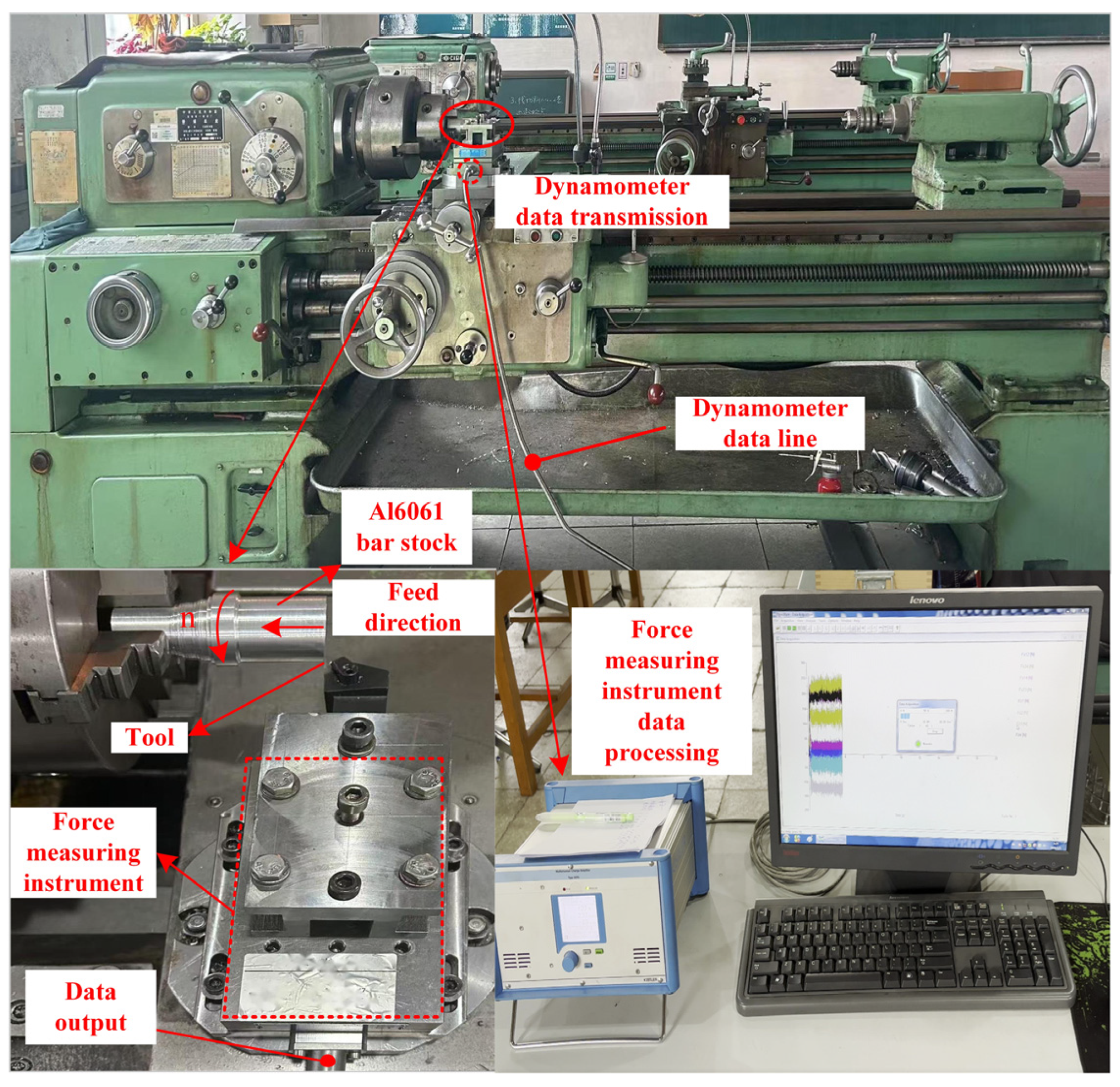
3.2.1. Cutting Experiment

Cutting experiments were conducted on a conventional lathe (CA6140 Shenyang First Machine Tool Works, Shenyang, China). A Swiss-made Kistler 9257B (Kistler Group, Winterthur, Switzerland) dynamometer was used to measure the cutting forces. The dynamometer is equipped with multiple built-in piezoelectric sensors, enabling the real-time and accurate acquisition of cutting forces in the X, Y, and Z directions. The workpiece material was 6061 aluminum alloy (Northeast Light Alloy Co., Ltd., Harbin, China), with a diameter of 40 mm and a length of 100 mm. The cutting tool used was a cemented carbide insert of type TNMA160404 TH03 (Toshiba Tungaloy Co., Ltd., Iwaki, Japan). To ensure consistency and to verify the accuracy of the simulation results presented earlier, the cutting parameters in the experiment were identical to those in the simulation: cutting speed, 120 m/min; feed rate, 0.3 mm/rev; depth of cut, 0.5 mm; and machining time, 10 min. The cutting experiment setup is shown in Figure 10. Tool wear and adhesion were observed and analyzed using a VHX-1000 (Keyence Corporation, Osaka, Japan) digital microscope with ultra-depth of field, which enabled the detailed examination of the tool’s rake face and wear patterns.

3.2.2. Cutting Force Experimental Results
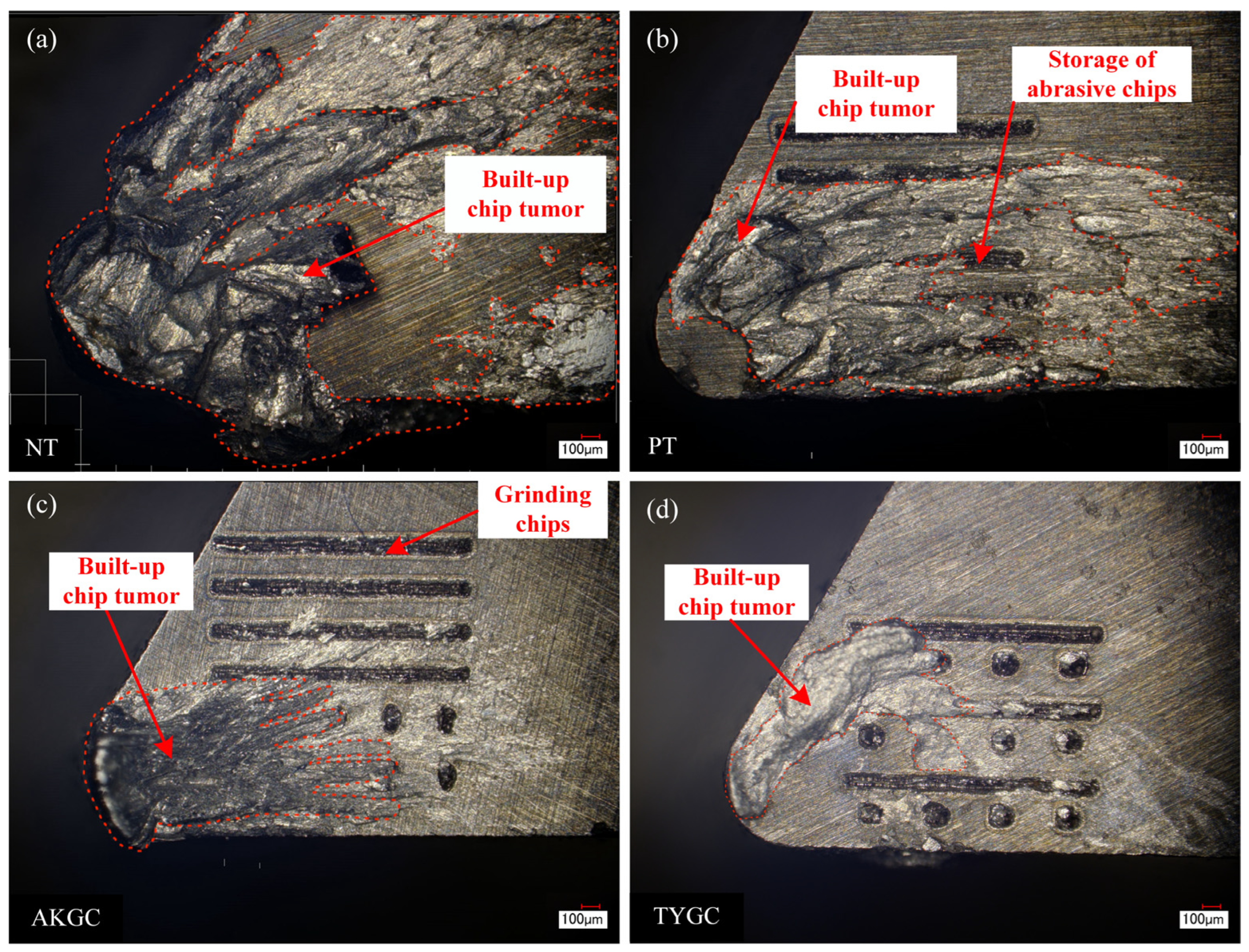
As shown in Figure 11a, the cutting force variation trends for the four types of tools exhibit similar characteristics. The NT (non-textured) tool showed the highest average cutting force of 278.99 N, with significant fluctuations due to the large contact area between the rake face and the chip and a high friction coefficient. This indicates poor cutting stability. With the introduction of the PT (groove-textured) tool, the average cutting force dropped to 219.6 N, representing a 21.26% reduction compared to the NT tool, and the cutting process became more stable. On this basis, the AKGC tool, which incorporates circular dimples in addition to grooves, further reduced chip adhesion. The average cutting force decreased to 201.39 N, a reduction of 27.83% compared to the NT tool. The best overall performance was observed with the TYGC tool, which combines elliptical dimples with grooves. This structure achieved the lowest average cutting force of 180.43 N, representing a 35.31% reduction from NT, and also exhibited the smoothest force curve. These results indicate significant synergistic advantages in friction reduction, chip evacuation, and wear resistance. Figure 11b compares the simulated and experimental cutting forces. All four tools show a consistent decreasing trend. The relative errors between simulation and experiment were within 20%—NT (15.84%), PT (12.59%), AKGC (9.46%), and TYGC (9.03%)—demonstrating the accuracy and reliability of the simulation model. Overall, the micro-textured tools effectively reduced the tool–chip contact area, thereby decreasing the cutting force. The experimental results confirm the positive effect of structural optimization. Among them, the TYGC tool exhibited the best performance in terms of friction reduction, anti-adhesion, and tool life extension, indicating strong potential for practical applications.

3.2.3. Tool Wear

Figure 12 presents the wear comparison of different bionic micro-textured tools observed under an ultra-depth-of-field digital microscope. As shown in Figure 12a, the NT (non-textured) tool exhibited the most severe wear and adhesion damage. The adhesion area on the rake face reached 2.04 mm2, and extensive wear was observed along the main cutting edge. This is mainly attributed to the large tool–chip contact area and high cutting forces, which promote built-up edge (BUE) formation under high-temperature and high-pressure conditions, leading to severe adhesion and wear. In Figure 12b, the PT (groove-textured) tool showed a reduced adhesion area of 1.46 mm2, a 28.43% decrease compared to the NT tool. Slight wear was observed outside the groove region, while the interior remained mostly intact. Some debris was effectively stored in the grooves, which helped suppress adhesion-related damage. As shown in Figure 12c, the AKGC tool further reduced the adhesion area to 0.84 mm2 (a 58.82% reduction). Only slight wear was observed near the cutting edge. Although some circular dimples were partially filled with adhered chips, the groove structures remained intact and continued to function as debris reservoirs. Figure 12d shows that the TYGC tool achieved the best performance, with the smallest adhesion area of 0.62 mm2, a 69.61% reduction compared to the NT tool. Chip adhesion was significantly reduced. The groove texture effectively minimized the tool–chip contact area and promoted chip evacuation, while the elliptical dimples helped disperse contact pressure and generated a localized gas-bearing effect. These mechanisms jointly enhanced the tool’s anti-adhesion, friction reduction, and wear resistance performance. In summary, the composite bionic micro-textured tools demonstrated superior performance in reducing wear, suppressing built-up edge formation, and enhancing friction and wear resistance compared to single-textured tools, validating the effectiveness of the synergistic texture design.

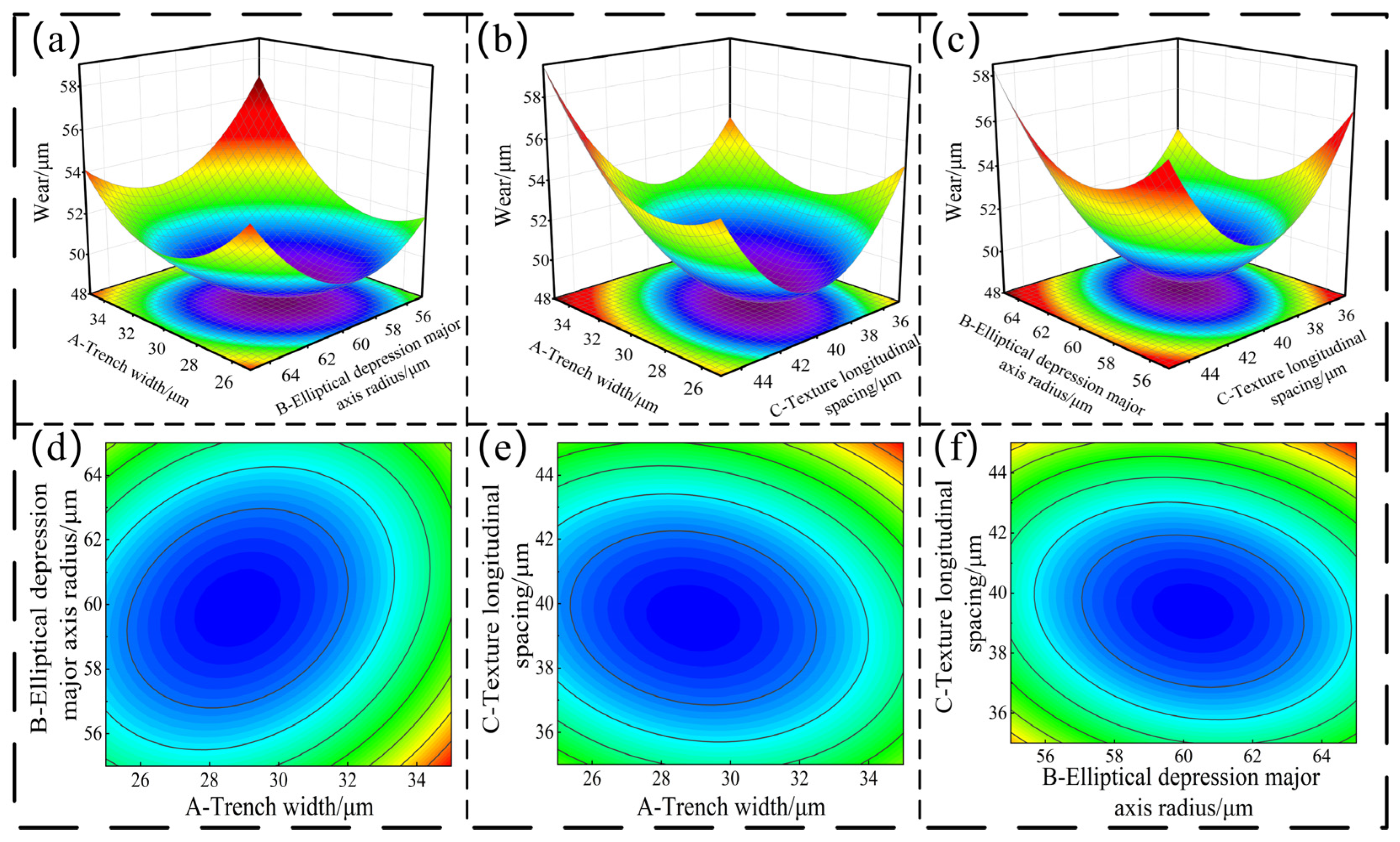
3.3. Parameter Optimization of Combined Bionic Micro-Textured Cutting Tools Using Response Surface Methodology

The Plackett–Burman (PB) experimental design method was employed to screen the micro-texture parameters, including the groove width, length, and depth; elliptical dimple major axis radius, transverse spacing, and ellipticity; and the longitudinal spacing of the micro-texture and its distance from the main cutting edge. The results indicated that the most significant factors affecting the tool wear area were the groove width, elliptical dimple major axis radius, and longitudinal spacing of the micro-texture. A schematic diagram of the microstructural parameters is shown in Figure 13. Based on the screening results, groove width (A), elliptical dimple major axis radius (B), and longitudinal spacing (C) were selected as the three factors for response surface analysis. Each factor was set at three levels, as shown in Table 4. Taking tool wear as the response variable, a Box–Behnken Design (BBD) response surface model with three factors and three levels was established. The response surface design table and corresponding simulation results, using cumulative wear depth as the response indicator, are presented in Table 5.
A response surface analysis of tool wear was conducted, and the ANOVA results are shown in Table 6. The model exhibited an F-value of 32.28 with a p-value less than 0.0001, indicating that the model has a highly significant effect on the tool wear response. The lack-of-fit p-value was 0.6134, which is greater than 0.05, suggesting that the lack of fit is not significant. The regression model therefore demonstrates a good level of fit. The coefficient of determination (R2) was 0.9765, and the adjusted R2 was 0.9462, indicating that the model is statistically reliable and fits the data well. In addition, the signal-to-noise ratio was 16.3340, which is greater than 4, confirming that the model is relatively insensitive to experimental noise and is suitable for predictive purposes.
An analysis of variance (ANOVA) was performed on the response indicator (tool wear), and the fitted regression model yielded the following response surface regression equation with wear Y as the response variable:
Y = 876.34 2.622 A 14.731 B 18.254 C 0.052 A B + 0.042 A C + 0.046 B C + 0.108 A 2 + 0.116 B 2 + 0.186 C 2
Figure 14 illustrates the pairwise interactions of key micro-texture parameters on tool wear, including response surface plots (a–c) and corresponding contour plots (d–f). As shown in Figure 14a,d, the interaction between the groove width and elliptical dimple major axis radius has a significant effect on wear. When the groove width is within the range of 25–35 μm, the wear depth remains below 0.56 μm, and it further decreases to below 0.52 μm when the width approaches approximately 33 μm. The optimal range for the elliptical dimple major axis radius is 57–63 μm, within which the minimum wear values are obtained. The contour plot in Figure 14d shows a typical 45°-tilted elliptical pattern, indicating a strong and comparable interaction between these two factors. Figure 14b,e present the interaction effects between the groove width and longitudinal spacing. When the groove width is reduced to 33 μm, wear decreases to below 0.54 μm, and lower wear values are also observed when the longitudinal spacing ranges between 37 μm and 43 μm. The elliptical contours in Figure 14e further confirm the presence of a significant interaction between these parameters, with the groove width showing a more pronounced effect, likely due to its role in chip flow regulation and contact area modulation. Figure 14c,f analyze the interaction between the elliptical dimple major axis radius and the longitudinal spacing. The results indicate that the influence of the major axis radius is greater than that of the longitudinal spacing, with the optimal wear performance occurring when the radius is between 57 and 63 μm and the spacing is between 37 and 43 μm. The elliptical contours in Figure 14f are skewed toward the axis radius direction, further validating its dominant effect. In summary, all three pairs of interactions—groove width vs. dimple radius, groove width vs. longitudinal spacing, and dimple radius vs. longitudinal spacing—exhibit significant influence on tool wear. Among them, the interaction between the groove width and elliptical dimple major axis radius is the most prominent. Optimizing these two parameters is key to minimizing tool wear and enhancing wear resistance and service life.
Based on the excellent fitting effect of the response surface model, the optimal experimental conditions were predicted. The prediction results indicate that under the conditions of a groove width of 19 μm, a long axis radius of 60 μm for elliptical pits, and a longitudinal spacing of 40 μm for texture, the best wear result can be obtained, with an expected wear amount of 49 μm. The variation in the groove width and longitudinal spacing can change the direction of chip flow, resulting in derivative secondary cutting that minimizes the curling radius, which is beneficial for chip breakage and removal and reduces tool surface wear. A change in the long axis of elliptical pits can alter the load-bearing capacity of micro-textures, thereby affecting the friction force and friction coefficient in the contact area of the cutting chip. To verify this prediction, simulation validation was conducted based on the above conditions. The tool wear cloud map is shown in Figure 15a, with a wear amount of 48.3 μm and an error rate of 1.4% compared to the predicted value. The temperature cloud map of the cutting tool is shown in Figure 15b, with a temperature of 141 °C. This error rate is quite low, and the actual value is close to the predicted value, which proves that the model is reasonable, accurate, and effective. It can be concluded therefore that the response surface model is a reliable tool for predicting and optimizing experimental conditions to obtain the best experimental results.

3.4. Verification of Wear Resistance and Fatigue Resistance Characteristics of Micro-Textured Cutting Tools

The tool chip contact area is a critical area in cutting processing, and its contact state and friction characteristics determine the performance and service life of the tool. Intense friction between the workpiece and the cutting tool produces a huge quantity of heat, leading to a rapid rise in the temperature of the contact area and stress concentration under pressure. Surface texture can improve the contact state between the workpiece and the tool, decrease the actual contact area, and thus reduce the friction and heat generation in the contact area. This section reports a thermal coupling analysis conducted on three types of cutting tools. The sliding block and the workpiece are made of structural steel, and the sliding block moves relative to the workpiece in the X positive direction. A force of 100MPa is applied along the negative Z-axis direction to the upper slider, with a friction coefficient of 0.4 and a thermal conductivity coefficient of 11N/s/mm/°C. The solution is used to explore the changes in the surface equivalent stress, friction stress, and temperature of micro-textured cutting tools during dry friction, and to compare and verify the temperature and wear status of the optimal micro-textured parameter cutting tools.

3.4.1. Temperature Analysis of Sliders with Different Textures

We can observe the following by comparing the temperature analysis of sliders with different texture morphologies (Figure 16): In Figure 16a, the highest temperature of NT sliders is 33.5 °C. In Figure 16b, the highest temperature of the PT sliders is 22% (7.5 °C) lower than that of non-textured sliders. The temperature of TYGC sliders in Figure 16c is 24% (8.1 °C) lower than that of non-textured sliders. The surface temperature of non-textured cutting tools shows a large red area, while the temperature distribution on the surface of textured cutting tools is more uniform. A high-temperature area is concentrated on the right side, and the change in temperature is low. According to Formula (16), the actual contact length between the tool and chip is proportional to the average temperature of the tool chip contact area. The placement of the texture reduces the actual contact area between the workpiece and the slider, thereby reducing the average temperature of the actual contact area. At the same time, the texture plays a role in heat dissipation. The temperature analysis results of different textured sliders are consistent with the cutting temperature trend of textured cutting tools mentioned earlier, which once again verifies the authenticity of the previous simulation and also indicates that the TYGC has better resistance to bond damage compared to other textures.

3.4.2. Friction Stress Analysis of Sliders with Different Textures

Comparing the friction stress analysis of sliders with different texture morphologies (Figure 16), the highest friction stress of NT sliders is 99.1 MPa (Figure 16d), and its stress distribution is on the right edge. As shown in Figure 16e, the highest friction stress of the PT is reduced by 1.3% (1.3 MPa) compared to the non-textured tool, and the stress distribution is relatively uniform. As shown in Figure 16f, the TYGC tool reduces friction stress by 14% (14 MPa) compared to the non-textured tool, indicating that this texture has good drag reduction and wear resistance effects, providing a theoretical basis for the cutting performance of the TYGC cutting tool mentioned earlier.

3.4.3. Analysis of Wear Morphology of Sliding Blocks with Different Textures

Figure 16 shows a simulation analysis of the wear and friction performance of the slider using the APDL command and Archard wear equation without considering temperature and frictional heat. The sliding block and workpiece are made of WC and 6061 aluminum alloy, respectively. The sliding block moves relative to the workpiece in the positive X direction and applies a force of 80N along the positive Z axis to the workpiece. The friction coefficient is set to 0.4.
As shown in Figure 16g, the wear area distribution on the surface of the non-woven sliding block is mainly focused in the center area of the surface, with a large wear area. This observation result is in line with the wear situation of the non-woven tool mentioned earlier, further confirming the characteristics of the non-woven surface during the wear process. In Figure 16h, the wear area of the PT is mainly concentrated at the edge of the slider, and the presence of texture effectively reduces surface wear. In Figure 16i, the wear area distribution on the TYGC surface is relatively uniform, avoiding large-scale wear. Combining Formulas 9 and 10, the placement of the texture reduces the contact area between the sliders, which causes a decline in the normal stress as well as the friction force at the blade–chip contact interface. This reduction further causes a decline in the resultant force at the contact interface. It is important to state that the resultant force at the contact interface is one of the fundamental causes of tool adhesion damage. Using the TYGC tool can therefore decrease the resultant force at the contact interface, thereby suppressing the occurrence of tool adhesion damage.
Figure 17 shows the instantaneous wear volume changes in surface sliders with different textures. All three textures show an upward trend, among which the wear volume change curve of the TYGC slider is smoother compared to the other two sliders, indicating that the wear rate of the TYGC slider is slower, while the wear volume curves of the NT and PT sliders are steeper. At 0.2s, the wear volume of the TYGC slider is smaller compared to the other two types of sliders, indicating that it has better drag reduction and wear resistance characteristics.

4. Conclusions

The cemented carbide tools used in the machining of aluminum alloys often suffer from rapid wear and severe adhesion damage, significantly shortening tool life. To address this issue, a bionic micro-texture was applied to the rake face of the cutting tool. A combined approach of finite element simulation and cutting experiments was employed to systematically investigate the cutting performance of micro-textured tools. The results demonstrated that bionic micro-textures offer significant advantages in reducing cutting force and temperature, suppressing wear and built-up edge formation and thereby effectively improving tool life and machining quality. Based on the above study, the following conclusions were drawn:
(1)
The TYGC tool, featuring a composite micro-texture of elliptical dimples and grooves, outperformed both non-textured and single-textured tools with regard to the main cutting force, cutting temperature, tool wear, and the cutting stability. It also produced chips with a smaller curling radius, which promoted chip breakage and rapid evacuation, thereby improving the finish of the workpiece surface.
(2)
Cutting experiments confirmed that the TYGC tool exhibited the lowest cutting force and the smallest adhesion area on the rake face during actual machining. It achieved the most stable cutting process and the lightest wear morphology. The experimental findings were in strong agreement with the simulation results, fully demonstrating the reliability and practical adaptability of the composite bionic micro-texture in enhancing comprehensive tool performance.
(3)
Response surface methodology was used to optimize the texture parameters of the tool. The following optimal texture configuration was determined: a groove depth of 50 μm, groove width of 19 μm, elliptical dimple major axis radius of 60 μm, ellipticity of 0.5%, transverse spacing of dimples of 120 μm, longitudinal spacing of 40 μm, distance from cutting edge of 50 μm, and groove length of 90 μm. These parameters provide theoretical and data support for the design and fabrication of composite textured tools with enhanced performance.
(4)
The study determined and validated the mechanism by which the TYGC composite structure improves friction reduction and anti-adhesion in dry cutting environments. It effectively suppressed adhesion damage on the rake face, thereby enhancing cutting stability and extending tool life.
(5)
A mathematical model was developed to describe the effects of micro-textures on the friction force and temperature at the tool–chip interface. The model clarified how the texture reduces interfacial friction and heat generation by shortening the effective contact length. The simulation results confirmed the accuracy of the model, while experimental findings regarding cutting force, wear morphology, and built-up edge distribution were consistent with the simulation trends, further verifying the actual friction-reducing and temperature-lowering effects of the TYGC tool and its effectiveness in suppressing adhesion-related damage.
To further verify the effectiveness of this study, we compared our results with recent research on micro-textured cutting tools. For example, Wu et al. [28] reported that when machining Ti–6Al–4V, the use of circular dimpled micro-textured tools reduced the cutting force by 15% and the chip–tool interface temperature by approximately 10%. Xu et al. [29] found that applying coated micro-textured tools in aluminum alloy machining decreased the cutting force by about 21.6% and the temperature by 7.6%. In contrast, the TYGC composite micro-textured tool proposed in this study achieved more significant performance improvements under similar conditions, including an approximately 30% reduction in main cutting force, 11% reduction in rake face temperature, and 27% reduction in tool wear depth. Compared with existing studies, the proposed tool shows more prominent advantages in reducing friction, lowering temperature, and improving wear resistance. These improvements are mainly attributed to the synergistic effect of the elliptical dimples and groove textures, as well as the optimized design of the structure parameters achieved through the response surface methodology, which endows the tool with enhanced friction-reducing, heat-dissipating, and wear-resistant capabilities.

Author Contributions

Conceptualization, Y.C., D.W., M.Z., H.M. and C.L.; Data curation, Y.C., D.W., H.M., Y.X. and Q.L.; Formal analysis, Y.X., Q.L. and H.J.; Funding acquisition, Y.C. and D.W.; Investigation, Y.C., M.Z., H.M., Q.L., Y.X., F.W. and Q.H.; Methodology, C.L.; Project administration, Y.C.; Resources, M.Z. and H.J.; Software, Y.C., D.W., M.Z., C.L., F.W. and Q.H.; Supervision, H.J.; Validation, F.W. and Q.H.; Visualization, D.W.; Writing—original draft, Y.C. and D.W.; Writing—review and editing, Y.C. and D.W. All authors have read and agreed to the published version of the manuscript.

Funding

This research was supported by the General Project of Heilongjiang Postdoctoral Fund (LBH-Z23301). This research was funded by the Research Projects of Basic Scientific Research Business Expenses of Provincial Colleges and Universities in Heilongjiang Province (145409603).

Institutional Review Board Statement

Not applicable.

Informed Consent Statement

Not applicable.

Data Availability Statement

The original contributions presented in this study are included in the article. Further inquiries can be directed to the corresponding author.

Conflicts of Interest

Authors Youzheng Cui and Hui Jiang were employed by the company QiQiHar Heavy CNC Equipment Co., Ltd. The remaining authors declare that the research was conducted in the absence of any commercial or financial relationships that could be construed as a potential conflicts of interest.

References

  1. Ding, P.; Huang, X.; Li, Y. Time-varying dynamic modeling of micro-milling considering tool wear and the process parameter identification. Mech. Based Des. Struct. Mach. 2024, 52, 8658–8684. [Google Scholar] [CrossRef]
  2. Wang, H.; Deng, W.; Wang, S. Precipitates Generation Mechanism and Surface Quality Improvement for 6061 Aluminum Alloy in Diamond Cutting. J. Wuhan Univ. Technol.–Mater. 2024, 39, 150–159. [Google Scholar] [CrossRef]
  3. Chanyathunyaroj, K.; Samit, W.; Poonthananiwatkul, C.; Phetchcrai, S. Effect of coatings on the mechanical properties and fatigue life of 6061 aluminum alloys. Trans. Indian Inst. Met. 2021, 74, 2135–2147. [Google Scholar] [CrossRef]
  4. Liang, Z.Q.; Li, M.Z.; Chen, B.C.; Zhou, T.F.; Li, S.D.; Yan, P.; Lin, X.Y.; Zang, S.Y.; Wang, X.B. Preparation and cutting performance of microtexture tool based on micro-grinding method. Surf. Technol. 2020, 49, 143–150. [Google Scholar]
  5. Xu, M.G.; Song, E.Y.; Zhang, H.X.; Cheng, X.; Wu, Z.W. Simulation and experimental research on cutting of ultra-hard material tools with groove microtexture. Surf. Technol. 2021, 50, 363–370. [Google Scholar]
  6. Musavi, S.H.; Sepehrikia, M.; Davoodi, B.; Niknam, S.A. Performance analysis of developed micro-textured cutting tool in machining aluminum alloy 7075-T6: Assessment of tool wear and surface roughness. Int. J. Adv. Manuf. Technol. 2022, 119, 3343–3362. [Google Scholar] [CrossRef]
  7. Baumann, R.; Bouraoui, Y.; Teicher, U.; Selbmann, E.; Ihlenfeldt, S.; Lasagni, A.F. Tailored laser structuring of tungsten carbide cutting tools for improving their tribological performance in turning aluminum alloy Al6061 T6. Materials 2023, 16, 1205. [Google Scholar] [CrossRef]
  8. Sugihara, T.; Nishimoto, Y.; Enomoto, T. Development of a novel cubic boron nitride cutting tool with a textured flank face for high speed machining of Inconel 718. Precis. Eng. 2017, 48, 75–82. [Google Scholar] [CrossRef]
  9. Sun, X.; Li, J.; Zhou, J.; Chen, K.; Du, H.; Cui, D.; Hu, Y.; Duan, J.-A. Reducing the adhesion effect of aluminum alloy by cutting tools with microgroove texture. Appl. Phys. A 2019, 125, 601. [Google Scholar] [CrossRef]
  10. Wang, Y.; Zhao, J.; Sun, Y. Performance of micro-grooved carbide tools in dry turning of aluminum alloys. Metals 2022, 12, 1147. [Google Scholar]
  11. Javidikia, M.; Sadeghifar, M.; Songmene, V.; Jahazi, M. Effect of turning environments and parameters on surface integrity of AA6061-T6: Experimental analysis, predictive modeling, and multi-criteria optimization. Int. J. Adv. Manuf. Technol. 2020, 110, 2669–2683. [Google Scholar] [CrossRef]
  12. Singh, J.; Khanduja, D. A review on fabrication and characterization of aluminium metal matrix composites with reinforced particulates. Mater. Today Proc. 2021, 46, 10251–10255. [Google Scholar]
  13. Sahoo, G.R.; Das, D.; Satpathy, M.P.; Nanda, B.K.; Panda, A.; Sahoo, A.K. Effect of cutting factors on surface quality of AA7075 alloy: A case study while turning with ZrCN coated WC inserts. AIP Conf. Proc. 2024, 3007. [Google Scholar]
  14. Feng, X.; Meng, C.; Lian, W.; Fan, X.; Wei, J. Optimization analysis of microtexture size parameters of tool surface for turning GH4169. Ferroelectrics 2023, 607, 186–207. [Google Scholar] [CrossRef]
  15. Fan, L.; Deng, Z.; Gao, X.; He, Y. Cutting performance of micro-textured PCBN tool. Nanotechnol. Precis. Eng. 2021, 4, 023004. [Google Scholar] [CrossRef]
  16. Li, B.B.; Chen, L.; Zhao, W.; Yu, M.; Zhang, K. Simulation study on optimization of texture parameters of micro textured cutting tools. Mod. Manuf. Eng. 2020, 91–96. [Google Scholar]
  17. Le, Q.Z.; Lei, X.L.; Wu, B.T.; Zhang, J.C.; Xiao, Z.Y. Optimization study on surface groove texture parameters of high temperature alloy cutting tools. Mach. Tool. Hydraul. 2021, 49, 6–11. [Google Scholar]
  18. Yu, Q.; Zhang, X.; Miao, X.; Liu, X.; Zhang, L. Performances of concave and convex microtexture tools in turning of Ti6Al4V with lubrication. Int. J. Adv. Manuf. Technol. 2020, 109, 1071–1092. [Google Scholar] [CrossRef]
  19. Fu, Y.H.; Pan, C.Y.; Fu, H.; Zhou, Y.H.; He, G.Y. Experimental study on the friction and wear properties of laser texturing texture on the surface of mold steel. Lubr. Seal. 2018, 43, 1–6. [Google Scholar]
  20. Fu, Y.H.; Li, Y.D.; Kang, Z.Y.; Gu, Y.L.; Zhang, F. Experimental study on the influencing factors of cutting performance of textured carbide cutters. Tool. Technol. 2018, 52, 16–19. [Google Scholar]
  21. Zhang, K.; Deng, J.; Xing, Y.; Li, S.; Gao, H. Effect of microscale texture on cutting performance of WC/Co-based TiAlN coated tools under different lubrication conditions. Appl. Surf. Sci. 2015, 326, 107–118. [Google Scholar] [CrossRef]
  22. Tu, C.; Guo, X.; Guo, D. Comparison of machinability of self-lubrication ceramic tools with different morphological micro-textures. Mech. Eng. Mater. 2018, 42, 47–51, 57. [Google Scholar]
  23. Cheng, W.; Outeiro, J.C. Modelling orthogonal cutting of Ti-6Al-4V titanium alloy using a constitutive model considering the state of stress. Int. J. Adv. Manuf. Technol. 2022, 119, 4329–4347. [Google Scholar] [CrossRef]
  24. Shen, W.; Xue, F.; Li, C.; Liu, Y.; Mo, X.; Gao, Q. Study on constitutive relationship of 6061 aluminum alloy based on Johnson-Cook model. Mater. Today Commun. 2023, 37, 106982. [Google Scholar] [CrossRef]
  25. Liu, Y.; Bie, H.N. Simulation and prediction of cutting force in micro milling of 6061 aluminum alloy. Tool. Technol. 2016, 50, 29–35. [Google Scholar]
  26. Poláková, I.; Zemko, M.; Rund, M.; Džugan, J. Using DEFORM software for determination of parameters for two fracture criteria on DIN 34CrNiMo6. Metals 2020, 10, 445. [Google Scholar] [CrossRef]
  27. Rajurkar, A.; Chinchanikar, S. Experimental investigation on laser-processed micro-dimple and micro-channel textured tools during turning of Inconel 718 alloy. Mater. Eng. Perform. 2022, 31, 4068–4083. [Google Scholar] [CrossRef]
  28. Wu, Z.; Xing, Y.; Chen, J. Improving the performance of micro-textured cutting tools in dry milling of Ti-6Al-4V alloys. Micromachines 2021, 12, 945. [Google Scholar] [CrossRef]
  29. Xu, T.; Xie, L.; Ma, C.; Li, Q. Investigation of cutting performance of coated micro-textured tools for cutting aluminum alloys. Mech. Sci. 2025, 16, 195–208. [Google Scholar] [CrossRef]
Figure 1. Schematic diagram of biomimetic microstructure features on the back surface of dung beetles and 3D modeling of cutting tools. (a) Bionic design prototype—dung beetle; (b) 3D model of the cutting tool; (c) non-textured; (d) groove-textured; (e) circular dimple–groove hybrid texture; (f) elliptical dimple–groove hybrid texture.
Metals 15 00697 g001
Figure 2. Grid division of cutting tools and workpieces.
Metals 15 00697 g002
Figure 3. Force analysis diagram of the contact interface between cutting tools and chips.
Metals 15 00697 g003
Figure 4. Stress distribution diagram of textured cutting tool’s contact interface.
Metals 15 00697 g004
Figure 5. Schematic diagram of heat transfer.
Metals 15 00697 g005
Figure 6. Cutting force response and friction sensitivity for different tool structures. (a) Variation of main cutting force with time for different bionic micro-textured tools; (b) Cutting force of different bionic micro-textured tools under various friction conditions.
Metals 15 00697 g006
Figure 7. Fringes of cutting temperature distribution on front face of different micro-texture tools: (a) non-textured; (b) groove-textured; (c) circular dimple–groove hybrid texture; (d) elliptical dimple–groove hybrid texture.
Metals 15 00697 g007
Figure 8. Fringes of accumulated wear depth distribution on front face of different micro-texture cutting tools: (a) non-textured; (b) groove-textured; (c) circular dimple–groove hybrid texture; (d) elliptical dimple–groove hybrid texture.
Metals 15 00697 g008
Figure 9. Comparison of macro morphology of chips of different bionic micro-texture tools.
Metals 15 00697 g009
Figure 10. Experimental setup for the dry cutting test.
Metals 15 00697 g010
Figure 11. (a) Cutting force variation with time for different micro-textured tools; (b) comparison between simulated and experimental cutting forces for different tool structures.
Metals 15 00697 g011
Figure 12. Wear morphologies of the rake face for different micro-textured tools. (a) non-textured; (b) groove-textured; (c) circular dimple–groove hybrid texture; (d) elliptical dimple–groove hybrid texture.
Metals 15 00697 g012
Figure 13. Schematic diagram of microstructural parameters.
Metals 15 00697 g013
Figure 14. Response surface analysis of the interaction effects between micro-texture parameters on tool wear. (ac) Response surface plots showing the effect of different texture parameters on tool wear: (a) Effect of trench width (A) and elliptical depression major axis radius (B); (b) Effect of trench width (A) and texture longitudinal spacing (C); (c) Effect of elliptical depression major axis radius (B) and texture longitudinal spacing (C); (df) Corresponding contour plots: (d) Contour of A and B; (e) Contour of A and C; (f) Contour of B and C.
Metals 15 00697 g014
Figure 15. Simulation verification cloud map of wear depth and temperature of TYGC cutting tools. (a) Simulation verification cloud map of wear depth of TYGC cutting tools; (b) simulation verification cloud map of TYGC tool temperature.
Metals 15 00697 g015
Figure 16. Distribution of interfacial temperature, frictional stress, and wear area for tools with different micro-texture structures. (ac) Temperature distribution; (df) frictional stress distribution; (gi) wear area distribution.
Metals 15 00697 g016
Figure 17. Instantaneous variation curve of sliding block wear volume on surfaces with different textures.
Metals 15 00697 g017
Table 1. Properties of the cemented carbide materials Adapted from Ref. [23].
Composition
(wt.%)
Density
(cm−3)
Flexural Strength (GPa)Thermal Conductivity
(W/(m·k))
Thermal Expansion Coefficient (10−4/K)
WC + 3%Co13.81.0887.95.3
Table 2. Mechanical properties of the aluminum alloy AL6061 Adapted from Ref. [24].
Method of ManufactureHardness (HRC)Yield Strength (MPa)Tensile Strength (MPa)Elongation
Extruded9.925230811.2
Table 4. Combination scheme of micropit texture parameters.
Level/FactorA—Trench Width (μm)B—Elliptical Depression Major Axis Radius (μm)C—Texture Longitudinal Spacing (μm)
−1155535
0206040
1256545
Table 5. Response surface design and results.
No.A—Groove WidthB—Elliptical Major Axis RadiusC—Longitudinal SpacingCumulative Wear Depth
10000.499
20−1−10.563
30000.483
4+10+10.595
50−1+10.567
6−1−100.523
7−10−10.548
80000.479
90000.481
10+1+100.538
110+1−10.536
120000.496
130+1+10.586
14−10+10.542
15+1−100.567
16−1+100.546
17+10−10.559
Table 6. Response surface variance analysis results.
SourceSum of SquaresdfMean SquareF-Valuep-ValueSignificance
Model211.55923.5132.28<0.0001Significant
A—Groove Depth12.5112.517.170.0043**
B—Groove Width0.24510.2450.33650.5801
C—Ellipse Radius8.8218.8212.110.0103*
AB6.7616.769.280.0187*
AC4.4114.416.060.0434*
BC5.2915.297.270.0308*
A230.58130.58420.0003**
B235.29135.2948.460.0002**
C290.85190.85124.76< 0.0001**
Residual5.170.7281
Lack of Fit1.730.56830.67020.6134Insignificant
Pure Error3.3940.848
Total216.6516
R20.9765
R2adj0.9462
Note: * indicates a significant effect; ** indicates a non-significant effect.
Disclaimer/Publisher’s Note: The statements, opinions and data contained in all publications are solely those of the individual author(s) and contributor(s) and not of MDPI and/or the editor(s). MDPI and/or the editor(s) disclaim responsibility for any injury to people or property resulting from any ideas, methods, instructions or products referred to in the content.

