Article

Microstructural Features and Mechanical Properties of Laser–MIG Hybrid Welded–Brazed Ti/Al Butt Joints with Different Filler Wires

1
School of Mechanical Engineering, Dalian University of Science and Technology, Dalian 116052, China
2
School of Materials Science and Engineering, Dalian Jiaotong University, Dalian 116028, China
*
Author to whom correspondence should be addressed.
Metals 2025, 15(6), 674; https://doi.org/10.3390/met15060674
Submission received: 7 May 2025 / Revised: 7 June 2025 / Accepted: 16 June 2025 / Published: 17 June 2025
(This article belongs to the Special Issue Laser Processing Technology for Metals)

Abstract

Laser–MIG hybrid welding–brazing was performed to join TC4 titanium alloy and 5083 aluminum alloy with ER5356, ER4043 and ER2319 filler wires. The effects of the different filler wires on the microstructural features and mechanical properties of Ti/Al welded–brazed butt joints were investigated in detail. The wetting and spreading effect of the ER4043 filler wire was the best, especially on the weld’s rear surface. Serrated-shaped and rod-like IMCs were generated at the top region of the interface of the joint with ER4043 filler wire, but rod-like IMCs did not appear at the joints with the other filler wires. Only serrated-shaped IMCs appeared in the middle and bottom regions for the three filler wires. The phase compositions of all the IMCs were inferred as being made up of TiAl3. The average thickness of the IMC layer of joints with the ER5356 and ER2319 filler wires was almost the same and thinner than that of the joint with the ER4043 filler wire. The average thickness was largest in the middle region and smallest in the bottom region for all the joints with the three filler wires. The average microhardness in the weld metal of ER5356, ER4043 and ER2319 filler wires could reach up to 77.7 HV, 91.2 HV and 85.4 HV, respectively. The average tensile strength of joints with the ER5356, ER4043 and ER2319 filler wires was 106 MPa, 238 MPa and 192 MPa, respectively. The tensile samples all fractured at the IMC interface and showed a mixed brittle–ductile fracture feature. These research results could help confirm the appropriate filler wire for the laser–MIG hybrid welding–brazing of Ti/Al dissimilar butt joints.

1. Introduction

Titanium alloy has been widely applied in aerospace, marine engineering and other industrial fields due to its low density, outstanding mechanical properties and excellent corrosion resistance. However, high costs severely limit its practical applications in many situations. In order to reduce the manufacturing costs, aluminum alloy, which has a lower cost but similar high specific strength, has been used to replace titanium alloy in some particular situations; e.g., Ti/Al composite structures were used in components like seat rails and easily corroded parts in aircraft manufacturing [1]. Therefore, applications of the Ti/Al composite structure have been receiving increasing attention [2,3], and the high-quality joining of titanium alloy and aluminum alloy has become a key part in the manufacturing process. Joining methods that are usually adopted are brazing, pressure welding and fusion welding. By comparison, fusion welding has been the most commonly used method due to the brazing and pressure welding being limited by the low mechanical performance [4] and the special joint configuration [5], respectively. However, numerous brittle intermetallic compounds (IMCs) are always inevitably generated at the interface during the fusion welding process due to significant differences in the metallurgical properties of Ti/Al dissimilar metals, including in their melting point, thermal conductivity and expansion coefficient [6]. The existing IMCs at the interface remarkably reduced the mechanical properties of the Ti/Al dissimilar welded joints and were one of the important factors restricting the practical applications of the Ti/Al composite structures [7]. Therefore, how to achieve high-quality Ti/Al dissimilar joints has always been a research focus in manufacturing the Ti/Al composite structures.
In recent years, the welding–brazing method has been proposed and gradually developed for joining dissimilar metals [8,9,10]. During the welding–brazing process, the alloy with the lower melting point is melted while the alloy with the higher melting point is still retained as a solid, therefore effectively restraining the growth of the IMCs [11,12]. The metal inter-gas welding–brazing (MIG) is the most common method due to its low cost, superior gap tolerance and strong flexibility [13]. A large heat input would contribute toward generating thicker IMC layers during the MIG welding–brazing process, which would lead to an obvious reduction in the tensile strength of the welded–brazed joints [14]. With the characteristics and advantages of the low heat input, laser welding–brazing is a promising method for suppressing the IMC growth, and numerous research studies have been conducted on this topic. Leo et al. [15] demonstrated that the negative laser defocusing distance was beneficial for reducing the thickness of the IMC layer at the interface, which could increase the tensile strength of the laser welded–brazed Ti/Al dissimilar joints. Zhao et al. [16] indicated that offsetting the laser toward the Al base metal could weaken the interfacial reaction, i.e., an increase 0.3 mm to 0.7 mm could reduce the thickness of IMCs from 15 μm to 5 μm. However, a contrary conclusion was drawn by Malikov et al. [6], who pointed out that only a reduction in the IMC layer thickness occurred when the laser was offset toward the Ti base metal rather than toward the Al base metal. Xia et al. [17] and Chen et al. [18] showed that the laser oscillating path and frequency also had a remarkable influence on the growth of the IMC layer and the formation quality of the welded–brazed joints. However, the disadvantage of high assembly accuracy greatly limits the industrial applications of the laser welding–brazing in many fields.
Laser–MIG hybrid welding combines the advantages of the low heat input of laser welding and the outstanding gap tolerance of MIG welding, which has promising application prospects in the joining of dissimilar metals. Casalino et al. [19] indicated that laser–MIG hybrid welding–brazing had a stable molten weld pool and could realize the high-quality joining of dissimilar metals. According to Shaker et al. [20], laser–MIG hybrid welding–brazing can suppress the growth of the IMCs by controlling the exposure time of the base metal to the heat source. Gao et al. [21] demonstrated that the laser power had a more obvious influence on the growth of the IMCs as this provided the majority of the heat source at the interface. Zhao et al. [22] showed that the energy ratio of the laser and arc had a remarkable influence on the IMCs’ morphology and the mechanical properties of the laser–MIG hybrid welded–brazed dissimilar joints. The existing literature studies mainly focused on optimizing the process parameters to control the reaction at the interface and, thereby, to control the IMCs’ growth. It is worth noting that the reaction at the interface could also be adjusted by adding special alloying elements, which could also subsequently influence the growth of the IMCs [23,24]. Using different filler wires is the simplest and most feasible method to add special alloying elements into the brazed weld. However, very few relevant research studies on this topic have been reported.
In the present work, joining of the TC4 titanium alloy and the 5083 dissimilar aluminum alloy was performed by laser–MIG hybrid welding–brazing with ER5356, ER4043 and ER2319 filler wires. The effects of the filler wires on the microstructural features and mechanical properties of the Ti/Al welded–brazed butt joints were investigated in detail. The main goal was to confirm an appropriate filler wire for the laser–MIG hybrid welding–brazing of Ti/Al dissimilar butt joints in the high-speed train body manufacturing industry.

2. Materials and Methods

2.1. Materials

TC4 titanium alloy and 5083 aluminum alloy sheets with dimensions of 150 mm (length) × 100 mm (width) × 4 mm (thickness) were used as the base materials. In order to obtain welded–brazed joints with higher tensile strength, an I-shaped groove was adopted based on our previous research results in the present work. Before the laser–MIG hybrid welding–brazing procedure test, the base metals were successively subjected to mechanical grinding and acetone scrubbing to remove the oxide film and oil stains. Furthermore, in order to improve the spreading and wetting of the molten metal on the TC4 surface, its surface was coated by a noncorrosive flux suspension (KAlF4 power dissolved in acetone) with an average thickness of about 0.1 mm. ER5356, ER4043 and ER2319 filler wires of 1.2 mm diameter were used as filler metals in the welding–brazing experiments. The main chemical compositions of the base metals and the filler wires are shown in Table 1.

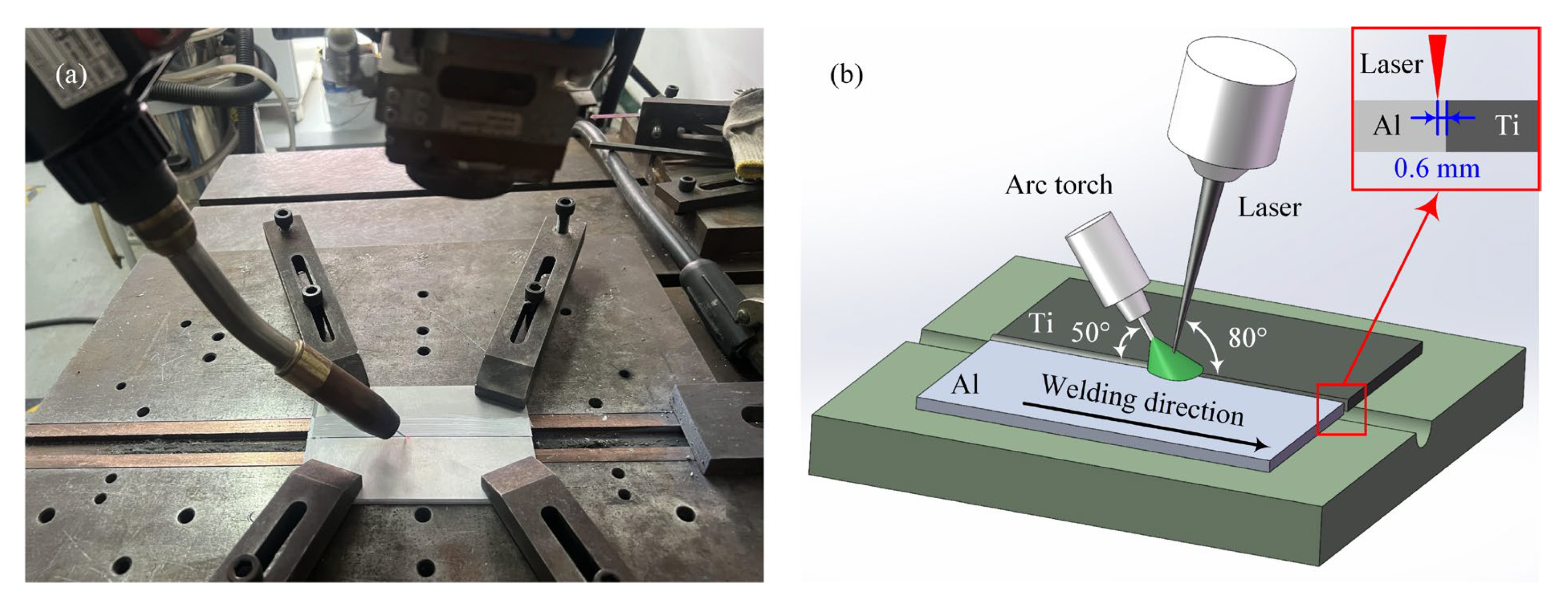
2.2. Welding–Brazing Procedure

The Ti/Al butt joints were created using a laser–arc hybrid welding system, which mainly included a 6 kW fiber laser (YLS-6000; IPG, Burbach, Germany), a welding machine with a unified adjusting function (TPS 500i CMT; FRONIUS, Wels, Austria) and a high-precision 6-axis welding robot (30 HA, KUKA, Augsburg, Germany). The emission wavelength and focusing diameters of the fiber laser were 1.6 μm and 0.2 mm, respectively. During the laser–MIG hybrid welding–brazing process, the laser was at the front and the arc was at the rear along the welding direction, and their angles to the workpieces were 80° and 50°, respectively. The distance between the laser and filler wire tip on the workpiece top surface was about 3 mm, and the defocusing distance of the laser was about +2 mm. In order to control the growth of the IMCs at the interface, the laser offset toward Al side was set at about 0.6 mm. High-purity Argon (99.999%) was used as the shielding gas, with a flow rate of 15 L/min. The laser–MIG hybrid welding–brazing process for the Ti/Al butt joints used in the present work is shown in Figure 1. For the three kinds of filler wires, the same process parameters were adopted in the laser–MIG hybrid welding–brazing experiments, as provided in Table 2. The values of the welding parameters were determined based on numerous prior experimental results.

2.3. Microstructure and Mechanical Property Tests

After the laser–MIG hybrid welding–brazing experiments, the cross-sections of the welded–brazed joints were successively dealt with by grinding with abrasive papers, polishing with diamond polishing agents and etching with Keller’s reagent. The macro formation of the Ti/Al butt joints was observed by optical microscopy (BX-51; OLYMPUS, Tokyo, Japan). The microstructure at the interface was observed by scanning electron microscopy (SEM) (SUPRA 55; ZEISS, Jene, Germany), and the chemical composition analysis of the IMCs layer was conducted by an energy dispersive spectrometer (EDS) (SUPRA 55; ZEISS, Jene, Germany) in the point-scanning mode. The microhardness distribution from the Al base metal to the fusion weld was measured by a digital micro-Vickers hardness tester (HVS-1000Z; HUAYIN, Laizhou, China) with a loading force of 0.98 N for 10 s. Tensile testing was carried out using an electronic universal testing machine (WDW-300E; STAR, Jinan, China) with a loading rate of 2 mm/min at room temperature, and an average of 3 specimens was taken as the final result. The specimen retained the original weld shape, and its geometric dimensions are shown in Figure 2.

3. Results and Discussion

3.1. Weld Formation

The weld surfaces and cross-sections of the laser–MIG hybrid welded–brazed Ti/Al butt joints with different filler wires are shown in Figure 3. For the weld surface formation, the front surface was fine, without any obvious defect, while the rear surface was unspread at the joint with the filler wire of ER5356; the melted metal could not be effectively spread on the Ti base metal, as shown in Figure 3a. For the joints with the ER2319filler wire, the melted metal was able to spread better on the Ti base metal on both the front and rear surfaces, as shown in Figure 3e,f. The reason for this difference is that the melting point of the ER2319 filler wire is lower than that of ER5356, which results in better spreading performance [25]. Furthermore, the uniformity and continuity of the rear surface for the joint with the ER4043 filler wire was the best, as shown in Figure 3c,d. The main reason for this was that the ER4043 filler wire had the highest content of silicon, which enhanced the fluidity of the molten pool [26].
For the weld cross-section formation, it was found that the unspread phenomenon was only exhibited on the rear surface of the joint with the ER5356 filler wire. The spreading distances of the melted metal on the front surface of the Ti base metal were about 1.3 mm, 1.7 mm and 1.1 mm for joints with the ER5356, ER4043 and ER2319 filler wires, respectively, as shown in Figure 3b,d,f. Meanwhile, the corresponding spreading distances on the rear surface were 0 mm, 1.2 mm and 0.8 mm. The comparison results indicated that the spreadability of the ER4043 filler wire was the best while that of the ER5356 filler wire was the worst, and that of the ER2319 filler wire was between those. Meanwhile, for the joints with the ER4043 and ER2319 filler wires, their wetting angles of the melted metal on the Ti base metal were 22° and 36°, respectively, as shown in Figure 3d,f. The results proved that the ER4043 filler wire had the best wettability. The higher Si content of ER4043 filler wire was the main reason for the improvement in the spreadability and wetting of the melted metal on the Ti base metal, which was also demonstrated by Wang et al. [27].

3.2. Microstructural Features

The morphology, phase composition and thickness of the IMC layer significantly influence the mechanical properties of the Ti/Al welded–brazed joints [28]. In order to comprehensively and deeply study the influence of the filler wire on the IMC layer, three regions, namely the top, middle and bottom of the interface along the thickness direction, were selected in this work. The IMC layer’s microstructural features in the above three regions are shown in Figure 4. Meanwhile, the possible phases at locations 1–10 in Figure 4 were confirmed by the EDS analysis, and the results are listed in Table 3.
For the joints with ER5356 and ER2319 filler wires, only continuous single-layer serrated-shaped IMCs could be observed in the top, middle and bottom regions of the interface, as shown in Figure 4a–c,g–i, while porosity defects appeared in the IMC layers. The difference was that more porosity defects could be find in the IMC layers of joints with the ER2319 filler wire, especially in the bottom region, as shown in Figure 4i. For the joint with the ER4043 filler wire, two-layer IMCs composed of continuous serrated-shaped IMCs near the Ti base metal and noncontinuous rod-like IMCs near the fusion zone could be observed in the top region, as shown in Figure 4d. Meanwhile, we also found that some rod-like IMCs were broken into the molten pool, which might be attributable to the relatively fast flow rate of the molten pool with the ER4043 filler wire. However, in the middle and bottom regions, only continuous single-layer serrated-shaped IMCs could be observed, as shown in Figure 4e,f. According to the composition analysis results listed in Table 3, the Ti/Al atomic ratios in locations 1–10 were all close to 1:3; therefore, the phase compositions of all the IMCs, including serrated-shaped and rod-liked IMCs, could be inferred to consist of TiAl3.
The average thickness of the IMC layers in the top, middle and bottom regions of the interface of the Ti/Al butt joints with different filler wires is shown in Figure 5. The average thickness of the IMC layer in the top, middle and bottom regions of the joint with the ER5356 filler wire was 0.99 μm, 1.18 μm and 0.87 μm; 1.37 μm, 1.62 μm and 1.02 μm for the joint with the ER4043 filler wire, and 1.01 μm, 1.37 μm and 0.90 μm for the joint with the ER2319 filler wire. The results indicated that the average thickness of the IMC layer in the same region was almost the same for the joints with the ER5356 and ER2319 filler wires, which was smaller than that of joints with the ER4043 filler wire. Comparing the average thickness of the IMC layer in different regions, it was found that for all the joints, regardless of the type of filler wire, the average thickness was largest in the middle region, the smallest in the bottom region, and in-between in the top region. The main reason for this phenomenon was that the cooling rate in the middle region was lower than that in the top and bottom regions, because the thickness of the IMC layer was mainly dependent on the welding thermal cycle [16,29].

3.3. Mechanical Properties

The microhardness distribution from the fusion zone to the Al base metal of the joints with different filler wires is shown in Figure 6. For the three kinds of filler wires, the microhardness distribution had the same variation tendency: it was lowest in the weld metal zone, highest in the Al base metal zone, and in-between these in the heat-affected zone (HAZ). Furthermore, it was found that the average microhardness in the weld metal made from the ER4043 filler wire reached up to 91.2 HV, which was larger than the 77.7 HV and 85.4 HV of the weld metal made from the ER5356 and ER2319 filler wires. The higher microhardness of the weld metal with the ER4043 filler wire is mainly due to the formation of a harder Al-Si eutectic mixture during the welding process [27]. There were no significant differences in the microhardness values of the heat-affected zones for different filler wire joints, which might be because they had the same welding heat input.
The tensile testing results of the laser–MIG hybrid welded–brazed Ti/Al butt joints with different filler wires are shown in Figure 7. The results indicated that the average tensile strength of joints with the ER5356, ER4043 and ER2319 filler wires was 106 MPa, 238 MPa and 192 MPa, while their average elongation was 1.8%, 3.1% and 2.9%, respectively. Because the IMCs of the joints with the three filler wires had the same phase composition and similar thickness, the lowest average tensile strength of the joints with ER5356 filler wire was most probably due to the poor spreading and wetting of the melted metal on the Ti base metal. This indicates that the spreadability and wettability of the melted metal on the Ti base metal is also an important factor influencing the tensile strength of the brazed-welded Ti/Al butt joints [30]. Compared with the joints with the ER4043 filler wire, the average tensile strength of the joints with the ER2319 filler wire was lower, which might be due to the porosity defects existing in the IMC layer, which would significantly reduce the bearing capacity [31], especially in the bottom region. All the tensile testing specimens fractured at the IMC layer for the three kinds of filler wires, as shown in Figure 7b.
The fracture morphologies of the tensile testing specimens of the joints with different filler wires are shown in Figure 8. The EDS composition analysis results of locations 1–8 in Figure 8 are listed in Table 4. From Figure 8a,c,e, it can be seen that some flat regions of different sizes appeared on the fracture surface. According to the EDS analysis results of locations 2, 4 and 8 in Table 4, the flat regions could be inferred to be composed of the Ti base metal. These results also indicated that the fracture was initiated between the Ti base metal and the IMC layer and showed a typical brittle fracture feature. The EDS analysis result of locations 1, 3, 5, 6 and 7 in Figure 8 indicated that these areas were mainly composed of Al atoms and were weld metals. There were dimples observed in the above areas, and these showed a typical ductile fracture feature, as shown in Figure 8b,d,f. Therefore, the tensile sample fractures all showed a mixed brittle–ductile fracture feature.

4. Conclusions

(1)
Compared with the ER5356 and ER2319 filler wires, the spreading and wetting of melted metal on the Ti base metal was the best when using the ER4043 filler wire, which had the largest spreading distance and the smallest wetting angle. Furthermore, the unspread phenomenon was exhibited on the rear surface of the joint with the ER5356 filler wire.
(2)
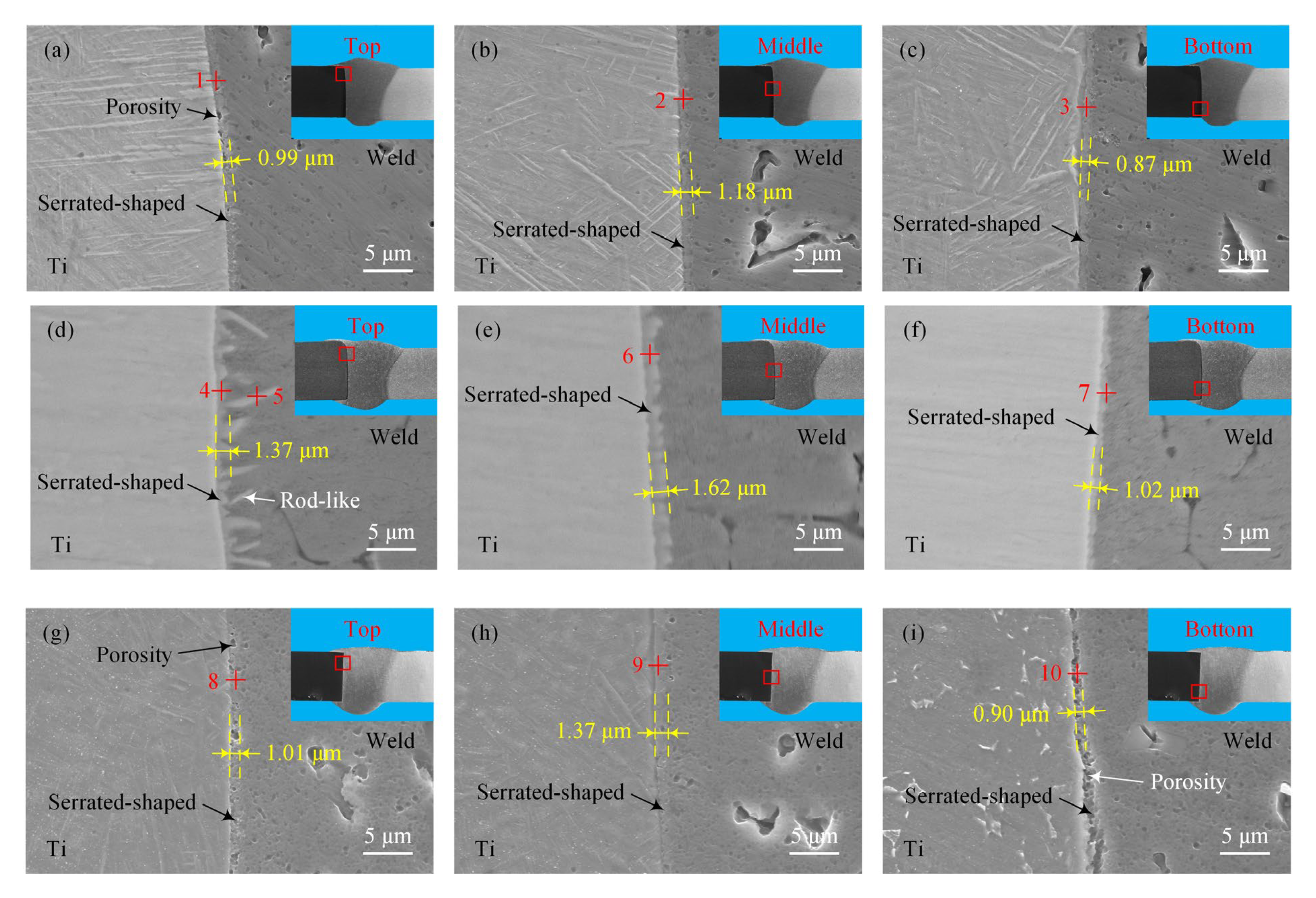
Two-layer IMCs composed of serrated-shaped and rod-like IMCs were generated in the top region of the interface of the joints with the ER4043 filler wire, but only serrated-shaped IMCs could be observed in the middle and bottom regions. Only single-layer serrated-shaped IMCs appeared in the joints with the ER5356 and ER2319 filler wires. The phase compositions of all the IMCs were inferred to consist of TiAl3.
(3)
The average thickness of the IMC layer in the same region was almost the same for joints with the ER5356 and ER2319 filler wires, which was smaller than that of joints with the ER4043 filler wire. Meanwhile, for all the joints with the three different filler wires, the average thickness was largest in the middle region, while the smallest was in the bottom region.
(4)
The microhardness distribution of the joints with different filler wires had the same variation tendency: lowest in the weld metal zone, highest in the Al base metal zone, and in-between in the heat-affected zone. The average microhardness in the weld metal reached up to 77.7 HV, 91.2 HV and 85.4 HV in the joints with the ER5356, ER4043 and ER2319 filler wires, respectively.
(5)
The average tensile strength of the joints with the ER5356, ER4043 and ER2319 filler wires was 106 MPa, 238 MPa and 192 MPa, respectively. The poor spreading and wetting of the melted metal on the Ti base metal might be the main reason for the joints with the ER5356 filler wire having the lowest average tensile strength. The tensile testing specimens all fractured at the IMC layer, and the fractures all showed a mixed brittle–ductile fracture feature.

Author Contributions

Conceptualization, X.Z. and Z.Y.; methodology, X.Z. and Z.Y.; validation, X.Z. and Z.Y.; formal analysis, Y.H. and H.Z.; investigation, Y.H. and S.D.; resources, Z.Y.; data curation, Y.H. and Z.Y.; writing-original draft, Z.Y.; writing—review and editing, X.Z. and Z.Y.; visualization, Y.H., H.Z. and S.D.; supervision, X.Z. and Z.Y.; project administration, Z.Y.; funding acquisition, X.Z. All authors have read and agreed to the published version of the manuscript.

Funding

This research was funded by the Liaoning Provincial Education Department Scientific Research Foundation of China (grant number JYTMS20230514).

Data Availability Statement

The original contributions presented in this study are included in the article. Further inquiries can be directed to the corresponding author.

Conflicts of Interest

The authors declare no conflicts of interest.

References

  1. Dou, T.; Yang, J.; Zeng, Y.; Zheng, M.; Xu, W.; Shi, J.; Zhang, H. The influence of FeCoCrNi HEA porous coating on dynamic wetting and spreading behaviors of AlSi alloy on steel substrate by laser irradiation. J. Manuf. Process. 2024, 125, 38–49. [Google Scholar] [CrossRef]
  2. Soni, R.; Verna, R.; Gary, R.K.; Sharma, V. A critical review of recent advances in the aerospace materials. Mater. Today Proc. 2024, 113, 180–184. [Google Scholar] [CrossRef]
  3. Möller, F.; Thomy, C.; Vollertsen, F. Joining of titanium aluminum seat tracks for aircraft applications system technology and joint properties. Weld. World 2012, 56, 108–114. [Google Scholar] [CrossRef]
  4. Xia, Y.; Ma, Z.; Du, Q.; Jiu, Y.; Guo, P.; Qin, J.; Li, S.; Zhang, X.; Zhou, P.; Hu, J.; et al. Microstructure and properties of the TiAl/GH3030 dissimilar joints vacuum-brazed with a Ti-based amorphous filler metal. Mater. Charact. 2024, 207, 113520. [Google Scholar] [CrossRef]
  5. Zhao, H.; Yu, M.; Jiang, Z.; Zhou, L.; Song, X. Interfacial microstructure and mechanical properties of Al/Ti dissimilar joints fabricated via friction stir welding. J. Alloys Compd. 2019, 789, 139–149. [Google Scholar] [CrossRef]
  6. Malikova, A.; Vitoshkina, I.; Orishicha, A.; Filippova, A.; Karpova, E. Microstructure and mechanical properties of laser welded joints of Al-Cu-Li and Ti-Al-V alloys. J. Manuf. Process. 2020, 53, 201–212. [Google Scholar] [CrossRef]
  7. Chen, X.; Lei, Z.; Chen, Y.; Han, Y.; Jiang, M.; Tian, Z.; Bi, J.; Lin, S. Microstructure and tensile properties of Ti/Al dissimilar joint by laser welding-brazing at sub-atmospheric pressure. J. Manuf. Process. 2020, 56, 19–27. [Google Scholar] [CrossRef]
  8. Chen, S.; Li, L.; Chen, Y.; Huang, J. Joining mechanism of Ti/Al dissimilar alloys during laser welding-brazing process. J. Alloys Compd. 2011, 509, 891–898. [Google Scholar] [CrossRef]
  9. Song, L.; Wei, S.; Rao, W.; Li, Z.; Zhang, Y. Optimization of welding parameters during Ti-TA2/5A06Al dissimilar double-sided cold arc metal inert gas welding. J. Mater. Eng. Perform. 2022, 31, 9714–9726. [Google Scholar] [CrossRef]
  10. Kuryntsev, S. A review: Laser welding of dissimilar materials (Al/Fe, Al/Ti, Al/Cu)-methods and techniques, microstructure and properties. Materials 2022, 15, 122. [Google Scholar] [CrossRef]
  11. Gao, M.; Chen, C.; Gu, Y.; Zeng, X. Microstructure and tensile behavior of laser arc hybrid welded dissimilar Al and Ti alloys. Materials 2014, 7, 1590–1602. [Google Scholar] [CrossRef]
  12. Li, Z.; Zhang, Y.; Yang, Y.; Feng, J.; Zhang, L. Properties study on Ti/Al butt joining by GMAW/GTAW hybrid welding-brazing. Mater. Res. Express 2023, 10, 116518. [Google Scholar] [CrossRef]
  13. Lin, H.L.; Chen, P.A. Effects of parameters on welding performance of the Ti/Al butt-joint in advanced plasma-MIG hybrid welding. Int. J. Adv. Manuf. Technol. 2024, 130, 2065–2083. [Google Scholar] [CrossRef]
  14. Xu, W.; Wang, W.; Yang, Q.; Xiong, J.; Zhang, L.; He, H. CMT twin welding-brazing of aluminum to titanium. Weld. World 2022, 66, 1121–1130. [Google Scholar] [CrossRef]
  15. Leo, P.; D’Ostuni, S.; Nobile, R.; Mele, C.; Tarantino, A.; Casalino, G. Analysis of the process parameters, post-weld heat treatment and peening effects on microstructure and mechanical performance of Ti-Al dissimilar laser weldings. Metals 2021, 11, 1257. [Google Scholar] [CrossRef]
  16. Zhao, J.; Geng, S.; Jiang, P.; Song, M.; Xu, B.; Luo, Q. Experimental and numerical research on formation mechanism of intermetallic compounds in laser brazing welding for Ti/Al dissimilar alloy. J. Mater. Res. Technol. 2024, 31, 2930–2944. [Google Scholar] [CrossRef]
  17. Xia, H.; Zhang, S.; Wu, J.; Ma, Y.; Xu, L.; Li, H.; Yuan, J.; Yang, B.; Tan, C.; Wu, T. Homogenizing interfacial IMC distribution and enhancing strength of laser welded-brazed Al/Ti butt joint by oscillated scanning. J. Mater. Res. Technol. 2025, 35, 6226–6236. [Google Scholar] [CrossRef]
  18. Chen, X.; Lei, Z.; Chen, Y.; Han, Y.; Jiang, M.; Tian, Z.; Bi, J.; Lin, S.; Jiang, N. Effect of laser beam oscillation on laser welding-brazing of Ti/Al dissimilar metals. Materials 2019, 12, 4165. [Google Scholar] [CrossRef]
  19. Casalino, G.; Leo, P.; Mortello, M.; Perulli, P.; Varone, A. Effects of laser offset and hybrid welding on microstructure and IMC in Fe-Al dissimilar welding. Metals 2017, 7, 282. [Google Scholar] [CrossRef]
  20. Shaker, M.A.; Jain, M.K.; Chen, J.Z. Deformation behavior of steel-to-aluminum tailor blanks made by laser/MIG hybrid and cold metal transfer brazing methods. Int. J. Adv. Manuf. Technol. 2020, 110, 3061–3076. [Google Scholar] [CrossRef]
  21. Gao, M.; Chen, C.; Mei, S.; Wang, L.; Zeng, X. Parameter optimization and mechanism of laser-arc hybrid welding of dissimilar Al alloy and stainless steel. Int. J. Adv. Manuf. Technol. 2014, 74, 199–208. [Google Scholar] [CrossRef]
  22. Zhao, Y.; Sun, H.; Zhao, X.; Zhao, H.; Liu, F.; Yang, B.; Chen, B.; Tan, C. The effect of inhomogeneous microstructure on the properties of laser-MIG hybrid welded 316L/AH36 dissimilar joints. J. Mater. Res. Technol. 2024, 28, 4088–4096. [Google Scholar] [CrossRef]
  23. Furuya, H.S.; Sato, Y.T.; Sato, Y.S.; Kokawa, H.; Tatsumi, Y. Strength improvement through grain refinement of intermetallic compound at Al/Fe dissimilar joint interface by the addition of alloying elements. Metall. Mater. Trans. A 2018, 49A, 527–536. [Google Scholar] [CrossRef]
  24. Wang, T.; Shukla, S.; Gwalani, B.; Komarasamy, M.; Reza-Nieto, L.; Mishra, R.S. Effect of reactive alloy elements on friction stir welded butt joints of metallurgically immiscible magnesium alloys and steel. J. Manuf. Process. 2019, 39, 138–145. [Google Scholar] [CrossRef]
  25. Yu, G.; Chen, S.; Zhao, Z.; Wen, Z.; Huang, J.; Yang, J.; Chen, S. Comparative study of laser welding-brazing of aluminum alloy to galvanized steel butted joints using five different filler wires. Opt. Laser Technol. 2022, 147, 107618. [Google Scholar] [CrossRef]
  26. Pouranvari, M.; Abbasi, M. Dissimilar gas tungsten arc weld-brazing of Al/steel using Al–Si filler metal: Microstructure and strengthening mechanisms. J. Alloys Compd. 2018, 749, 121–127. [Google Scholar] [CrossRef]
  27. Wang, S.; Qin, G.; Su, Y. Laser-MIG arc hybrid brazing-fusion welding of Al alloy to Galvanized steel with different filler metals. Acta Metall. Sin. (Engl. Lett.) 2013, 26, 177–182. [Google Scholar] [CrossRef]
  28. Chen, Z.; Cai, C.; Yu, J.; Huang, J.; Chen, H.; Li, L. Microstructure evolution and fracture behavior of laser welded-brazed titanium/aluminum joints with various gap sizes. J. Mater. Res. Technol. 2024, 29, 714–727. [Google Scholar] [CrossRef]
  29. Zhou, X.; Zhao, H.; Liu, F.; Yang, B.; Chen, B.; Tan, C. Influence of energy ration on microstructure and mechanical properties in the transition zone of hybrid laser-MIG welded Ah36/316L dissimilar joints. J. Mater. Res. Technol. 2021, 15, 4487–4501. [Google Scholar] [CrossRef]
  30. Wang, W.; Zhu, Z.; Xue, J. Microstructure and mechanical properties of Ti/Al dissimilar joints produced by laser-MIG welding-brazing. Int. J. Mod. Phys. B 2019, 33, 1940030. [Google Scholar] [CrossRef]
  31. Han, X.; Yang, Z.; Ma, Y.; Shi, C.; Xin, Z. Porosity distribution and mechanical response of laser-MIG hybrid butt welded 6082-T6 aluminum alloy joint. Opt. Laser Technol. 2020, 132, 106511. [Google Scholar] [CrossRef]
Figure 1. Laser–MIG hybrid welding–brazing for the Ti/Al butt joints: (a) experimental setup; (b) schematic diagram.
Metals 15 00674 g001
Figure 2. Tensile testing machine and specimen: (a) testing machine; (b) testing specimen.
Metals 15 00674 g002
Figure 3. Weld formation of the Ti/Al welded–brazed joints with different filler wires: (a,b) with ER5356; (c,d) with ER4043; (e,f) with ER2319.
Metals 15 00674 g003
Figure 4. Interfacial intermetallic compound (IMC) microstructures of the joints with different filler wires: (ac) with ER5356; (df) with ER4043; (gi) with ER2319.
Metals 15 00674 g004
Figure 5. Average thickness of the IMC layer in joints with the different filler wires.
Metals 15 00674 g005
Figure 6. Microhardness distribution from the weld metal to the Al base metal of the joints with different filler wires.
Metals 15 00674 g006
Figure 7. Tensile testing results of Ti/Al joints with different filler wires: (a) stress–strain curves; (b) tensile properties.
Metals 15 00674 g007
Figure 8. Fracture morphologies of the tensile testing specimens of the joints with different filler wires: (a) macrograph of a joint with ER5356; (b) details of area A; (c) macrograph with a joint with ER4043; (d) details of area B; (e) macrograph of a joint with ER2319; (f) details of area C.
Metals 15 00674 g008
Table 1. Chemical compositions of the base metals and filler wires used (wt. %).
MetalsAlTiSiFeCuMnZnMgV
TC46.19Bal./0.21////3.95
5083Bal.0.120.340.370.080.650.194.57/
ER5356Bal.0.130.220.360.070.780.065.23/
ER4043Bal.0.185.270.610.260.040.110.05/
ER2319Bal.0.160.180.266.370.350.100.180.11
Table 2. Laser–MIG hybrid welding–brazing parameters for the Ti/Al butt joints with different filler wires.
ParametersLaser Power
(kW)
Welding Speed
(m/min)
Wire Feeding
Speed (m/min)
Welding Current
(A)
Welding Voltage
(V)
Laser Offset
Distance (mm)
Values2.21.56.511218.20.6
Table 3. EDS analysis results of locations 1–10 from Figure 4 (at. %).
LocationsAlTiSiPossible Phase
175.4121.073.52TiAl3
272.3323.813.86TiAl3
377.4720.172.36TiAl3
472.3123.234.46TiAl3
571.6224.733.65TiAl3
669.5624.326.12TiAl3
777.2421.211.55TiAl3
874.2133.372.42TiAl3
973.3624.052.59TiAl3
1077.3320.342.33TiAl3
Table 4. EDS analysis results of locations 1–8 from Figure 8 (at. %).
LocationsTiSiAl
10.966.1592.89
291.363.774.87
31.395.1893.43
490.373.765.87
50.175.7694.57
60.875.9793.16
70.576.0293.41
892.023.194.79
Disclaimer/Publisher’s Note: The statements, opinions and data contained in all publications are solely those of the individual author(s) and contributor(s) and not of MDPI and/or the editor(s). MDPI and/or the editor(s) disclaim responsibility for any injury to people or property resulting from any ideas, methods, instructions or products referred to in the content.

