2.3.1. Model of the Hot Metal Temperature Drop in the Torpedo Car
The algorithm of the hot metal temperature calculation in the torpedo car is shown in
Figure 5. The individual mathematical sub-models were implemented in the C# environment.
Input loading:
The dimensions of the torpedo car, i.e., the inner diameter, inner length, outer diameter, outer length, mass capacity, hole dimension, wall thickness, and wall layer dimensions and thermophysical properties, are set in these models. Subsequently, the torpedo car wall’s temperatures are loaded.
The wall’s heat accumulation model:
The heat accumulated in the torpedo car wall is calculated in this model. The equation for the calculation of this heat is
where
is the heat accumulated in the torpedo car wall (J),
is the layer density between
and
temperatures (kg·m
−3),
is the layer volume between
and
temperatures (m
3),
is the layer-specific heat capacity between
and
temperatures (J·kg
−1·m
−1), 293.15 is the wall’s layer temperature in the cold state (K),
and
are the wall’s layer temperature in the actual state.
Preheating model:
The preheating process starts if a new torpedo enters the process, the wall of the torpedo car is repaired, or the heat accumulated in the torpedo car wall is low. The heat accumulated in the torpedo car wall is compared to the heat accumulated in the torpedo car wall at full charge. The full charge is determined from the wall temperatures calculated using Equation (
4) if the maximum temperature of the hot metal on the inner side of the torpedo car wall is considered. The maximum temperature of the hot metal was equal to the maximum tapping temperatures from the blast furnace.
The temperatures inside the wall of the torpedo car during preheating were calculated using Equation (
4). The Robin boundary condition was considered in the calculation, i.e., the input variables were the flue gas temperature inside the torpedo car (
) and the environment temperature outside the torpedo car (
). It was assumed that the heat flows along the inner and outer surface of the torpedo car are equal to the heat flow in the torpedo car wall below the surface (i.e., in the boundary elements). The temperature on the inner surface of the torpedo car was determined
The temperature on the outer surface of the torpedo car was determined using
where
is the heat transfer coefficient between the flue gas and the inner surface of the torpedo car (W·m
−2·K
−1) and
is the heat transfer coefficient between the outer surface of the torpedo car and the air (W·m
−2·K
−1).
Torpedo car wall cooling model:
This model simulates the torpedo car’s wall cooling process by calculating the torpedo car wall temperatures if the torpedo car is empty. The torpedo car is in a state between the end of pouring the hot metal into the ladle and the start of the torpedo car preheating or between the end of pouring the hot metal into the ladle and the start of the torpedo car filling.
The temperatures inside the wall of the torpedo car during wall cooling were calculated using Equation (
4). The Neumann boundary condition inside the torpedo car was considered, i.e., the heat flow along the inner surface of the wall is known. The Robin boundary condition outside the torpedo car was considered, i.e., the environment temperature outside the torpedo car is known. The temperature on the outer surface of the torpedo car was determined using Equation (
13).
It was assumed that the heat flow along the inner surface of the torpedo car is equal to the heat flow below the surface (i.e., in the first element).
Here,
is the area of the torpedo car inner surface (m
2), and
is the heat flow between the torpedo car inner surface and the environment through the hole of the torpedo car (W).
The heat flow
was determined using the sum of the heat convection (
5) flow and heat radiation flow (
6). The temperature
is the air temperature, and the temperature
is the temperature
. Area
A is the area of the hole of the torpedo car. The heat transfer coefficient
and emissivity
were determined using the thermophysical properties of the air and the torpedo car wall.
Hot metal weight increase model:
This model is run when hot metal tapping from the blast furnace into the torpedo car is in progress. A torpedo car can be filled during one or more tappings. The hot metal mass is set at the null value (i.e.,
) at the start of tapping. The hot metal mass in the torpedo car is calculated using
where
is the increase in mass over time
(kg).
The change in temperature of the hot metal in the torpedo car during tapping is calculated as
where
is the hot metal tapping temperature (K),
is the hot metal temperature in the torpedo car, and
is the hot metal mass in the torpedo car.
During tapping, the temperature of the hot metal is decreased due to heat losses to the torpedo car wall and the surroundings. The hot metal cooling model calculates these heat losses.
Hot metal cooling model:
This model calculates the drop in hot metal temperature during hot metal tapping, transport, and pouring out. The drop in temperature of the hot metal is caused by heat losses to the wall and the torpedo car’s surroundings
where
is the heat losses into the torpedo car wall (W),
is the heat losses through the torpedo hole at convection heat transfer (W),
is the heat losses through the torpedo hole at radiation heat transfer (W),
is the hot metal mass (kg),
is the hot metal temperature at actual time step (K),
is the hot metal temperature at the next time step (K),
is the hot metal specific heat capacity (J·kg
−1·K
−1), and
is the time step (s).
The temperature
is the hot metal temperature, and the temperature
is the air temperature at the time of convection (
5) and radiation (
6) heat loss calculation. The area
A is the area of the hole of the torpedo car. The heat transfer coefficient
and emissivity
were determined using the thermophysical properties of the hot metal and the air.
The temperatures in the torpedo wall needed to be determined to calculate the heat losses to the torpedo car wall. The procedure presented in the preheating model section was used for calculating the wall temperatures.
Subsequently, the heat losses to the wall were calculated using Equation (
5). The temperature
was the hot metal temperature
, and the temperature
was the inner surface wall temperature
. The heat transfer coefficient
was determined using the thermophysical properties of the hot metal. The area
A was considered the wall’s inner surface in places where hot metal comes into contact with the wall. The area
A is the function of the hot metal volume
because the hot metal mass is not constant, i.e., it increases during tapping and decreases during pouring out.
Hot metal weight decrease model:
This model is run when hot metal is poured from the torpedo car into the ladle. The torpedo car is emptied into two or more ladles. The change in the hot metal mass in the torpedo car is calculated
where
is the decrease in mass over time
(kg).
Similarly to tapping, the hot metal cooling model calculates heat losses to the torpedo car wall and the surroundings. The temperature of the hot metal is stored in the form of a vector when it is poured into the ladle. This vector contains decreasing values of the hot metal temperature and represents the input values of the hot metal temperature to the ladle model during its filling.
Outputs visualization:
The task of this function is to visualize hot metal temperature behavior using tables and graphs.
2.3.2. Model of the Hot Metal Temperature Drop in the Ladle
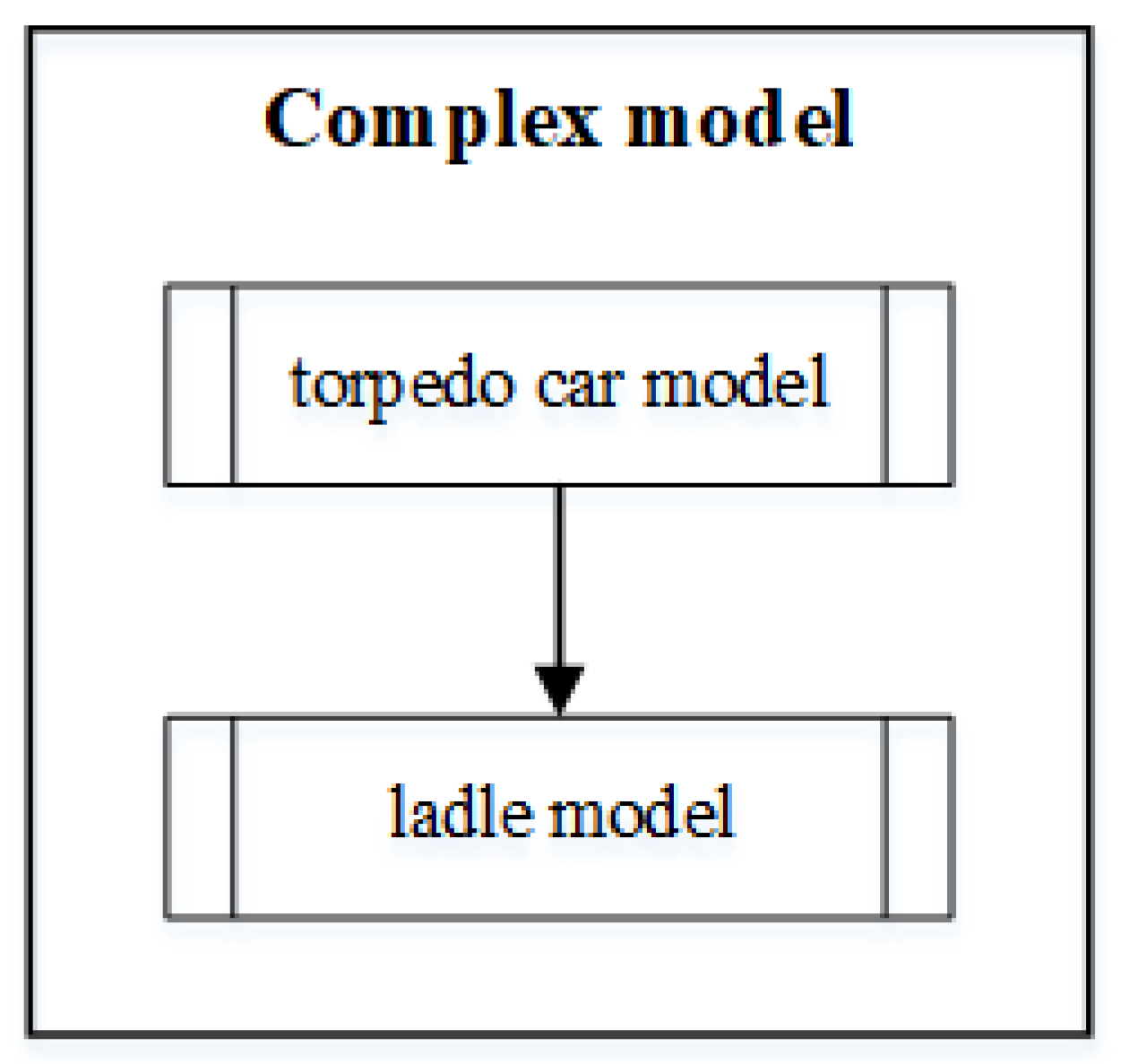
The algorithm of the hot metal temperature calculation in the ladle has a similar structure to the one shown in
Figure 5, but the ladle is filled with hot metal from the torpedo car. Subsequently, the desulfurization process is carried out in the ladle. After the desulfurization process is completed, the hot metal is poured into the oxygen converter. The individual mathematical sub-models were implemented in the C# environment.
Inputs loading:
The following variables are loaded and set in the ladle model:
The ladle mass capacity;
The height, the diameter of the pouring hole, and the diameter of the bottom;
The vertical and bottom wall layers’ dimensions and thermophysical properties;
The temperatures of the vertical wall and the temperatures of the bottom wall;
The temperatures of the hot metal poured into the ladle.
Wall heat accumulation model:
The heat accumulated in the ladle walls is calculated using Equation (
9) using the dimensions and thermophysical properties of the vertical and bottom ladle walls. The heat accumulated in the ladle is the sum of the heat accumulated in the vertical and bottom walls.
Preheating model:
The preheating process starts if a new ladle enters the process, the walls of the ladle are repaired, or the heat accumulated in the ladle walls is low, similar to the torpedo car. The full charge is determined from the wall temperatures calculated using Equation (
3) for the bottom wall and Equation (
4) for the vertical wall. The maximum temperature of the hot metal was equal to the maximum poured-out temperatures from the torpedo car.
The temperatures inside the walls of the ladle during preheating were calculated using Equation (
3) for the bottom wall and Equation (
4) for the vertical wall. Similarly to preheating the torpedo car, Equations (
11) and (
13) were used for the surface temperature calculations of the vertical wall. The surface temperatures of the bottom wall were determined using the equations expressed for the Cartesian co-ordinates. The temperature on the inner surface of the bottom wall was determined using
The temperature on the outer surface of the vertical wall was determined using
where
is the heat transfer coefficient between the flue gas and the inner surface of the ladle (W·m
−2·K
−1), and
is the heat transfer coefficient between the outer surface of the ladle and the air (W·m
−2·K
−1).
Ladle wall cooling model:
This model simulates the ladle’s wall cooling process by calculating the ladle walls’ temperatures if the ladle is empty. The ladle is in a state between the end of pouring the hot metal into the oxygen converter and the start of ladle preheating or between the end of pouring the hot metal into the oxygen converter and the start of ladle filling.
The temperatures inside the vertical wall were calculated using Equation (
4), and those inside the bottom wall were calculated using Equation (
3) during wall cooling. Equations (
15) and (
13) were used for the vertical wall surface temperature. The temperature on the outer surface of the bottom wall was determined using Equation (
23). The temperature on the inner surface of the bottom wall was calculated as
where
is the area of the bottom wall’s inner surface (m
2), and
is the heat flow between the bottom wall’s inner surface and the environment through the pouring hole of the ladle (W).
The heat flow
was determined using the sum of the heat convection (
5) flow and heat radiation flow (
6).
Hot metal weight increase model:
This model is run when the hot metal is poured from the torpedo car into the ladle. The ladle can be filled in sequence from one or more of the torpedo cars. At the start of pouring, the hot metal mass in the ladle is set at the null value (i.e.,
). The hot metal mass in the ladle is calculated using Equation (
16), and
is the increase in mass over time
. The hot metal temperature
decreases via the convection (
5) and radiation (
6) heat losses into the environment during pouring:
Subsequently, the change in temperature of the hot metal in the ladle during pouring is calculated using Equation (
16). The hot metal tapping temperature in this equation is replaced by the temperature of the hot metal poured out from the torpedo car.
Hot metal cooling model:
The hot metal temperature at the next time step is calculated similarly to Equation (
18), but the heat from the chemical reaction process
(determined by Equation (
7)) must also be considered:
Similar to the calculation of the heat losses to the torpedo wall, temperatures in the vertical and bottom ladle walls need to be determined. The wall temperatures were calculated using the procedure described in the preheating model section. Subsequently, two amounts of heat losses to the wall were calculated using Equation (
5) and summed, with the first used for the vertical wall and the second for the bottom wall. Area
A is the function of the hot metal volume
.
Hot metal weight decrease model:
This model runs when the hot metal is poured into the oxygen converter from the ladle. Equation (
19) calculates the change in the hot metal mass in the ladle.
Similarly to pouring into the ladle, the hot metal cooling model calculates the heat losses to the ladle walls and the surroundings. The temperature of the hot metal is stored in the form of a vector when it is being poured into the oxygen converter. This vector contains decreasing values for the hot metal temperature and represents the input values of the hot metal temperature to the next steelmaking process in the oxygen converter.
Output visualization:
Similar to the torpedo car, this function visualizes the hot metal temperature behavior using tables and graphs.

