Article

Influence of Welding Speed on the Microstructure and Mechanical Properties of Laser-Welded Joints in 316L Stainless Steel Sheets

by
Jianqiang Liu
1,
Yu Nie
1,
Qiaobo Feng
1,*,
Xiuyu Liang
1,
Haiyang Lei
2,
Sizhe Niu
3 and
Ming Lou
4
1
School of Energy and Mechanical Engineering, Shanghai University of Electric Power, Shanghai 201306, China
2
Shanghai FusionSmart Industry Equipment Co., Ltd., Shanghai 200090, China
3
School of Mechanical Engineering, Shandong University of Technology, Zibo 255000, China
4
Shanghai Key Laboratory of Digital Manufacture for Thin-Walled Structures, Shanghai Jiao Tong University, Shanghai 200240, China
*
Author to whom correspondence should be addressed.
Metals 2025, 15(6), 624; https://doi.org/10.3390/met15060624
Submission received: 26 April 2025 / Revised: 28 May 2025 / Accepted: 28 May 2025 / Published: 31 May 2025
(This article belongs to the Special Issue New Welding Materials and Green Joint Technology—2nd Edition)

Abstract

This study investigates the effect of welding speed on the microstructure and mechanical properties of pulsed laser lap-welded 0.2 mm 316L stainless steel sheets, commonly used in fuel cell bipolar plates. Welding speeds ranging from 6 to 26 mm/s were tested while other laser parameters remained constant. Results show that increasing welding speed reduces heat input, overlap factor, and weld dimensions. A transition from full to partial penetration occurs beyond 6 mm/s, with no visible heat-affected zone. The weld microstructure features columnar ferrite near fusion boundaries and globular ferrite in the center. Tensile–shear tests reveal that welds maintain higher strength than the base metal up to 22 mm/s, with all fractures occurring in the base material. An optimal speed range of 10–14 mm/s ensures defect-free joints with improved mechanical performance. These findings provide practical guidance for thin-gauge stainless steel welding in fuel cell applications.

1. Introduction

Owing to its outstanding corrosion, wear, and temperature resistance in welded structures, 316L stainless steel is extensively used in the automotive, chemical, and nuclear power industries [1,2,3,4]. In fuel cells, bipolar plates are often constructed from 316L stainless steel sheets. These plates support the membrane electrode, facilitate the separation of hydrogen and oxygen, and aid in heat conduction. Metallic bipolar plates are typically manufactured by cutting stamped single-polarity plates and subsequently joining two single-polarity plates through laser welding. To be effective, these plates must exhibit sufficient strength, airtightness, and resistance to harsh conditions, such as strong acids and high temperatures. Therefore, the welding process must be reliable, with minimal elemental segregation and residual stress in the welded joints [5]. Laser welding is a cutting-edge technique that offers many advantages. Its minimal heat input and restricted heat-affected zone help preserve the original properties of the material. Moreover, it reduces the risk of weld-producing precipitation, thus creating a favorable environment for high-quality welds [6,7,8].
Geng et al. [9] investigated the effects of welding speed by employing a pulsed Nd:YGA laser to weld AISI 304 and 420 stainless steel sheets. As the welding speed increased, a fusion zone with coarse ferrite and austenite grains was formed. When the peak temperature of the fusion zone decreased, the strength of the welded joints also decreased. Xu et al. [10] examined the impact of Al-Si coating on the shape and mechanical characteristics of laser-welded 22MnB5 steel joints at various welding speeds.
Palanisamy et al. [11] examined the influence of welding speed on the mechanical properties and microstructure of welded joints. They discovered that the welding speed significantly influenced the weld geometry. Moreover, they noted that increasing the welding speed resulted in the conversion of columnar crystals located at the weld core into equiaxed crystals.
In Min Hong’s [12] research, Inconel 625, fabricated by SLM, was laser welded and the effect of welding speed on the microstructure of the joint was investigated. With increasing welding speed, the grain size and the ratio of high angle grain boundary (HAGB) were decreased, and the tensile strength and elongation are improved. Then, Subhajit Mitra [13] observed that the laser welding at low speed or medium speed did not deteriorate the fatigue property significantly, with a drop of about 9–12% in fatigue limit, compared to the parent material.
Although laser lap welding has been widely applied in the joining of stainless steel materials, studies focusing on the effect of welding speed on 316L stainless steel—particularly in ultra-thin sheet configurations—remain limited. This study aims to fill this research gap by systematically examining the influence of welding speed on the weld morphology, microstructure, and mechanical properties of 0.2 mm thick 316L stainless steel joints using pulsed laser lap welding. The results establish a theoretical and practical foundation for optimizing welding parameters in thin-gauge stainless steel applications. A representative application is the manufacturing of metallic bipolar plates for proton exchange membrane fuel cells (PEMFCs) [14,15,16], where laser lap welding plays a critical role in achieving the required electrical conductivity and gas tightness. The insights obtained from this work provide valuable guidance for improving welding quality and enhancing the overall performance and reliability of PEMFC systems.

2. Materials and Methods

2.1. Materials

The material used was a 316L stainless steel sheet with dimensions of 100 mm × 30 mm × 0.2 mm (length × width × thickness). The chemical composition and mechanical properties according to the manufacturer’s certificate are presented in Table 1 and Table 2, respectively.

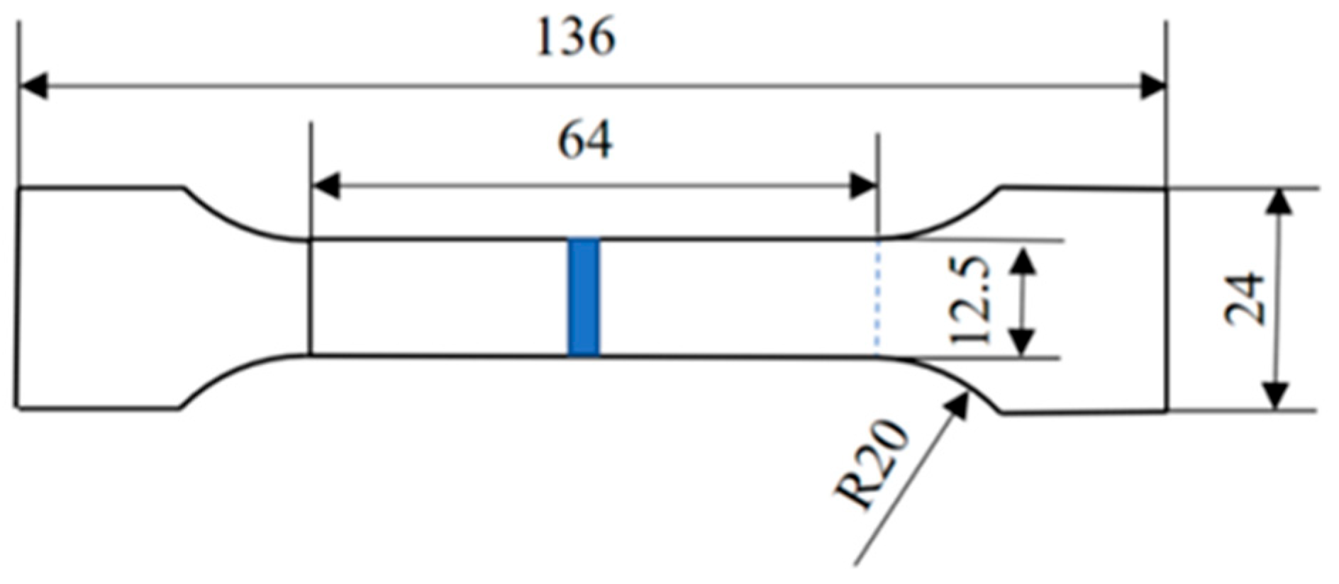
2.2. Experimental Setup

Lap welding tests on 316L stainless steel sheets were conducted using a JHM-4GX-300 pulsed laser welding machine (Wuhan Chutian Industrial Laser Equipment Co., Ltd., Wuhan, China) and an ABB robotic welding system (ABB Engineering Ltd., Shanghai, China). The process parameters are listed in Table 3.
To create welded specimens with dimensions of 100 × 30 × 0.2 mm, we use the wire electrical discharge machining (WEDM) to process the base metal. To prepare the specimen surfaces for welding, anhydrous ethanol was applied to remove surface stains and residual impurities. Because the 316L stainless steel sheet was thin, a specialized fixture was used to secure the base metal to the welding table and prevent thermal deformation during welding. Argon was used as a shielding gas with a flow rate of 0.1667 L/s. Figure 1 shows a schematic of the welding process.
The post-weld specimen was cut and sampled along the cross-section of the weld to assess the weld seam. Subsequently, it underwent Sample Cutting, Embedding, Grinding, Polishing and Corroding the Sample. An optical microscope was employed to measure the melt pool width and depth of penetration of the weld, enabling the observation of its macroscopic structure. Using the national standard GB/T 228.1-2021 [17], the post-weld specimen was subjected to tensile testing at a speed of 5 mm/min, with each group of tests being repeated thrice. The dimensions of the tensile specimens are illustrated in Figure 2. The microhardness of the welded joints was measured using a VH1102 Vickers hardness tester (BUEHLER, Lake Bluff, IL, USA). A load of 0.98 N was applied for 15 s, with a test point interval of 0.2 mm.

3. Results and Discussion

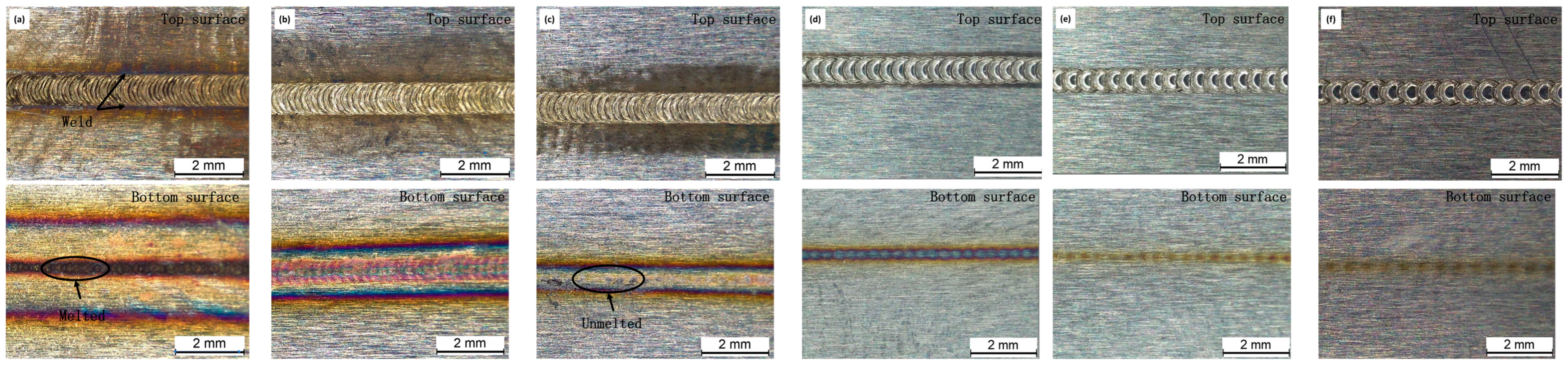
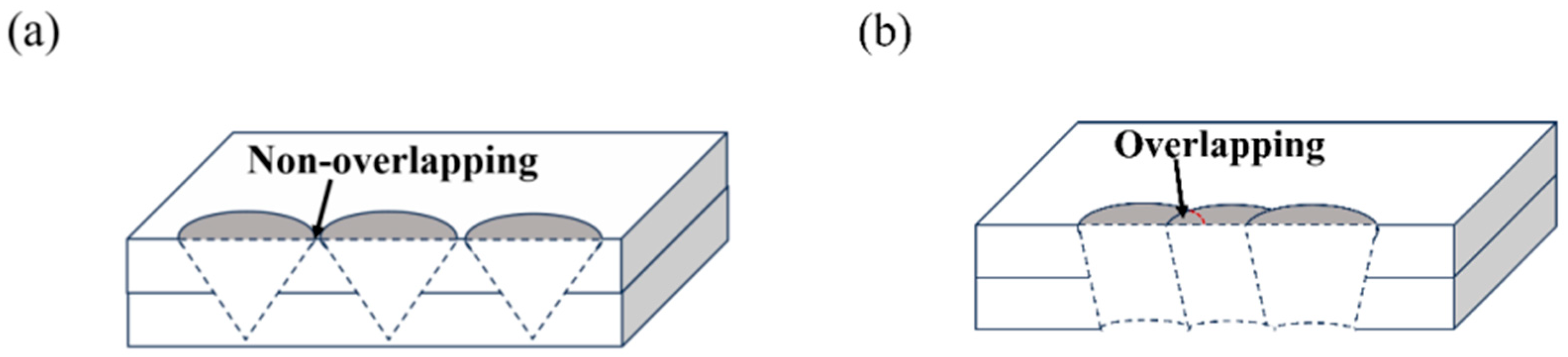
3.1. Effect of Welding Speed on Macromorphology

Figure 3a–f depict the top and bottom surfaces of the weld seam at various welding speeds. The shielding gas used in the welding process causes the formation a fish scale pattern on the front of the weld, thereby inhibiting oxidation. At welding speeds of 6 mm/s and 10 mm/s, a minor undercut occurs, leading to a reduced overlap rate between weld spots and a narrower width of the weld seam. As the welding speed increases, the fish scale pattern becomes less noticeable. The bottom surface of the weld is fully welded at the welding speed of 6 mm/s. However, burn-through marks and oxidation are evident. Increasing the welding speed causes the heat input to decrease, resulting in incomplete welding of the weld bottom surface. The heat transfer from a single pulse to the bottom of the burn marks causes oxidation phenomena, but these effects tend to diminish over time.
Figure 4 shows a schematic of the weld seams at different speeds. The interaction between adjacent welding spots contributes to weld formation. Examining the overlap factor of weld spots can help understand how welding speed affects surface molding during the welding process. When the welding speed is high, no continuous weld fusion zone forms between adjacent weld spots. This results in a lack of interaction between spots in the depth direction, as depicted in Figure 4a. Conversely, when the welding speed is low, an overlap zone forms between the weld spots at the surface, as illustrated in Figure 4b. This improves surface molding and facilitates interaction between weld spots in the depth direction, leading to increased weld joint strength.
Assuming all other conditions remain constant, an increase in welding speed leads to a decline in the weld spot overlap factor. This, in turn, results in a reduction in the melt pool width and depth of the weld. It is important to note that the welding speed directly affects the welding spot overlap rate, as shown in Equation (1) [18]. The overlap factor (Qf) depends on the welding speed, pulse frequency, weld spot diameter, and pulse width. Equations (2) and (3) indicate that the welding heat input (HI) is directly proportional to the average power and welding speed. Therefore, increasing the welding speed results in decreased heat input. This information is critical for determining the appropriate heat input when welding stainless steel sheet metal.
Q f = [ 1 ( V / f ) / ( D + V T ) ] × 100
P = P P T f
H I = P / V
where V denotes the welding speed (mm/s), f represents the pulse frequency (Hz), D is the weld spot diameter (mm), T stands for the pulse width (s), P is the average power (W), PP is the peak power (W), and HI denotes the heat input (J/mm).
Table 4 displays specific values for the overlap factor and heat input of welded spots. For standard weldments, the minimum overlap factor should be 65.2%. Seal weldments require a minimum overlap factor of 70%. At a welding speed of 6 mm/s, both the top and bottom surfaces of the weld are properly welded. In this case, the overlap factor is 87.2%, and the heat input is 20 J/mm. However, at a welding speed of 10 mm/s, the top surface exhibits a well-formed weld seam, while the bottom surface is not completely welded. This leads to a reduction in overlap factor to 77.3% and a heat input of 12 J/mm. Figure 5 illustrates the relationship between welding speed, overlap factor, and heat input. As the welding speed increases, the overlap factor decreases linearly. In contrast, the heat input initially decreases rapidly but then its rate of decrease gradually slows down.
When welding metal bipolar plates, it is imperative to satisfy the performance criteria and prevent the bottom surface of the plate from being welded through. Based on the test results, a moderate welding speed is necessary for a 0.2 mm thick 316L stainless steel sheet. To achieve the required weld joint overlap factor, the heat input should be at least 12 J/mm. It is also important to avoid welding through the bottom surface of the plate.

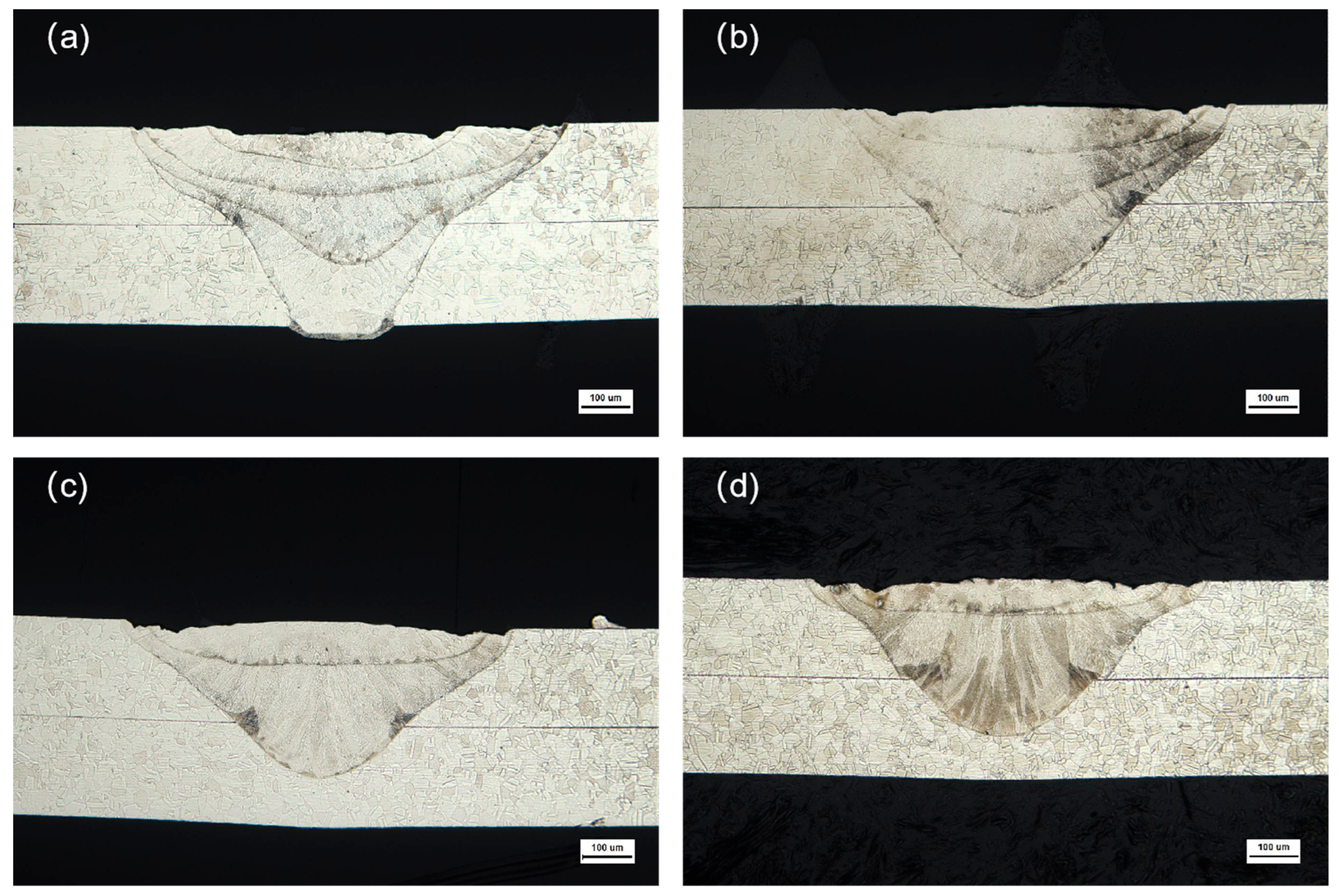
3.2. Effect of Welding Speed on Weld Microstructure

When we use a microscope (Leica Stereozoom S9i, Wetzlar, Germany) to measure the weld melt pool width and depth, it is important to ensure that the welding speed is not excessive, as this can result in a low joint overlap factor. To obtain accurate measurements, a cross-section of the weld must be intercepted along the center, as shown in Figure 4 The measurement of the weld melt pool width and depth is illustrated in Figure 6a. The middle melt pool width is a major factor affecting the joint tensile–shear force. Figure 6b depicts the correlation between the welding speed, melt pool width, and weld penetration depth. The variations in the upper melt pool width, middle melt pool width, and weld penetration depth are insignificant at welding speeds between 6 mm/s and 10 mm/s. The weld penetration depth remains relatively constant when the heat input reaches a certain threshold. As the welding speed increases, the heat input and total molten metal volume decrease, resulting in a downward trend in the upper melt pool width, middle melt pool width, and weld penetration depth. When the welding speed reaches 26 mm/s, the middle melt pool width measures 0.211 mm. This speed is excessively high because the upper and lower plates fail to form an effective connection, resulting in poor mechanical properties.
For stainless steel sheet metal, because of the fixed defocusing amount, the spot diameter is unchanged. This leads to minimal changes in the upper melt pool width, making the impact of welding speed variation on the upper melt pool width more significant than that on the weld penetration depth.
Figure 7 illustrates the microstructure evolution of welded joints across welding speeds ranging from 6 to 18 mm/s. As the welding speed increases, the fusion zone (weld pool) progressively narrows due to reduced heat input, which limits the volume of molten metal. Concurrently, the rapid cooling rates associated with elevated welding speeds promote the formation of a finer grain structure, enhancing mechanical properties. Notably, within the tested speed range, the joints exhibited remarkable microstructural consistency, with minimal defects such as porosity observed. This combination of refined grain morphology and defect suppression underscores the critical role of optimized welding parameters in achieving high-quality welds for demanding applications.
Figure 8 depicts the cross-sectional microstructure of a welded joint made from 316L stainless steel sheets. As shown in Figure 8a, the base metal and weld are not completely joined along the fusion line. However, the weld seam exhibits no flaws, such as porosity or cracks, and there is no noticeable difference between the base metals. The entire weld has no significant heat-affected zone because of the thin 316L stainless steel sheet and its low austenitic thermal conductivity. The high transient energy density of laser welding causes localized rapid heating, with minimal heat impact on the entire base metal. A clear demarcation line is visible on the upper part of the weld cross-section, indicating the overlap of multiple weld spots during the welding process. Irrespective of the cross-section location, the fusion line forms because of weld solidification, remelting, and subsequent solidification.
Figure 8b shows that the central boundary region of the joint microstructure has no heat-affected zone. The two base metals at the contact surface fail to form a smooth fusion line. At the edge of the joint, ferrite columnar crystals exhibit a distinct directional pattern that is approximately perpendicular to the fusion line growth. This pattern is most pronounced in the area near the contact surfaces of the two base metals. Figure 8c displays the microstructure of the weld edge near the base metal. The ferrite exhibits various forms with a clear directional pattern. Compared with Figure 8b, the columnar ferrite shape disappears and is replaced by short strips and spherical ferrite arranged in parallel. This change may be due to the thin base metal, rapid solidification rate of the weld, and unbalanced phase transition that transforms the original columnar ferrite into short bars and spheres.
In Figure 8d, the fusion line microstructure in the overlapping zone of the welded joints exhibits a regional dispersion of columnar ferrite and vermicular ferrite beyond the fusion line. During the solidification process of the molten pool after welding, the vermicular ferrite appears with no clear directional pattern. Figure 8e depicts the microstructure at the bottom of the weld center. The weld heat dissipation block at the bottom ensures an unobstructed weld fusion line, eliminating any heat-affected zones. The columnar crystals are perpendicular to both the fusion line and center of the weld.

3.3. Effect of Welding Speed on Mechanical Properties

Figure 9a indicates that when the welding speed falls within the range of 6–22 mm/s, the tensile–shear force undergoes fluctuations. Fractures within this speed range occur in the base metal. When the heat input exceeds 5.5 J/mm, the tensile–shear force carried by the welded joint exceeded the maximum load-bearing capacity of the base metal under the same test conditions. However, at a welding speed of 26 mm/s, the tensile–shear force is the smallest, at 451 N. Although there is minimal difference in the middle melt pool width at 22 mm/s and 26 mm/s, the overlap factor of the welded joints is lower at 26 mm/s. At 26 mm/s, the reduced heat input results in incomplete fusion between the upper and lower sheets, leading to a visible gap at the joint interface and a corresponding reduction in mechanical strength. Heat transfer occurs primarily through conduction, hindering the formation of a reliable connection that results in a joint with a low tensile–shear force.
Figure 9b shows that the average weld hardness varies with the welding speed. The base metal has a measured hardness of 165 HV. At all six welding speeds, the weld exhibits an average hardness 6–14% higher than that of the base metal, with values ranging from 176.8 to 188.3 HV. The weld attains its highest average hardness value of 188.3 HV at a welding speed of 6 mm/s. This increase in hardness compared with that of the base metal is due to the thinner base metal, accelerated post-weld cooling, limited diffusion of alloying elements, and formation of fine grains within the weld zone. As the welding speed increases, the weld zone experiences a decline in average hardness; however, the variation across the six welding speeds is minimal. This suggests that the welding speed has a limited impact on the weld hardness, even at low heat inputs. Overall, the hardness of the welded joints is enhanced.

4. Conclusions

The investigation of the effect of welding speed on the microstructure and mechanical properties of pulsed laser lap-welded 0.2 mm 316L stainless steel sheets showed that:
I
Welding speeds between 10 mm/s and 14 mm/s provide the best balance between sufficient heat input, appropriate overlap factor, and favorable mechanical performance, without causing defects such as burn-through or incomplete fusion. At a welding speed of 6 mm/s, the weld surface exhibits a fish scale morphology (commonly observed in pulsed laser welding [19]), while the bottom surface achieves full penetration but displays burn-through defects and oxidation. As the welding speed increases, reduced heat input leads to partial penetration with localized burn marks induced by single-pulse thermal conduction to the substrate. This aligns with Ref. [19], where excessive heat input at low speeds exacerbates burn-through, emphasizing the critical role of pulse parameter optimization (e.g., power, pulse duration) in weld morphology control.
II
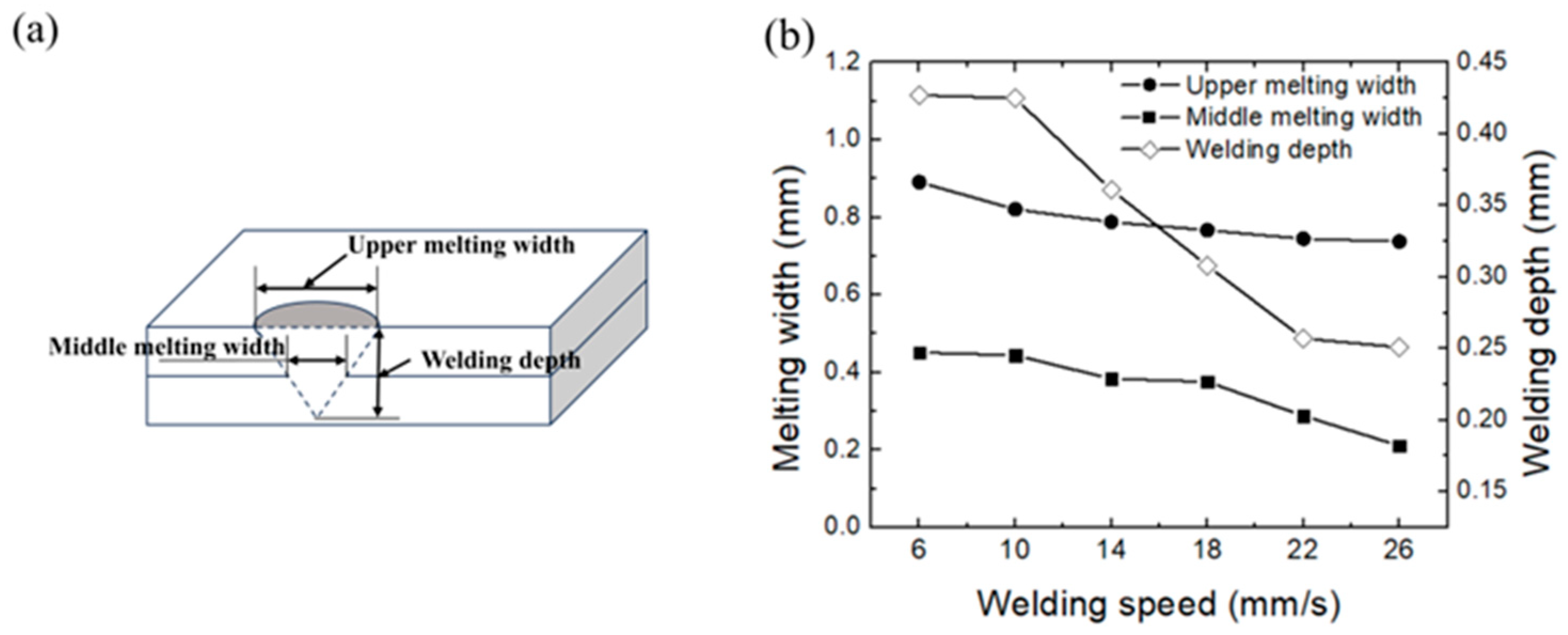
Increasing welding speed reduces heat input, causing decreases in upper melt width, middle melt width, and penetration depth until a threshold heat input stabilizes the penetration depth. No discernible heat-affected zone (HAZ) is observed due to the ultra-thin sheet geometry (0.2 mm) and rapid cooling. Ferritic columnar grains at the fusion boundary exhibit epitaxial growth perpendicular to the fusion line, while the weld core comprises short-lath ferrite and globular ferrite arranged in parallel. Compared to Ref. [20], where δ-ferrite transitions from skeletal to lathy morphology with increasing speed, the distinct globular-lath duplex structure here arises from thinner material (0.2 mm vs. 0.5 mm) and higher cooling rates. Ref. [21] attributes phase evolution to carburization-induced carbon diffusion, but in this study, hardness enhancement (6–14% over base metal) stems from grain refinement rather than carburization effects.
III
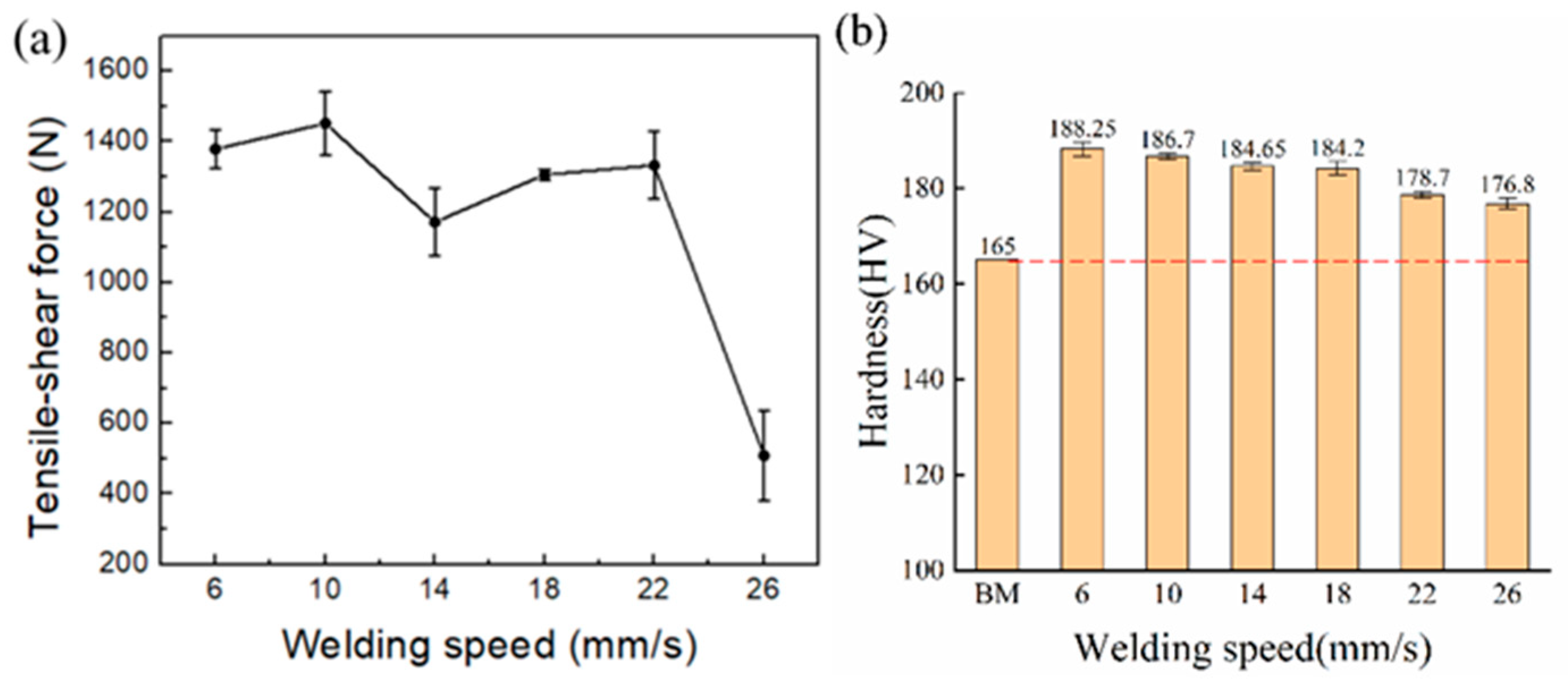
Within the welding speed range of 6–22 mm/s, the tensile–shear strength fluctuates slightly, with fractures consistently occurring in the base material, indicating weld integrity exceeding parent metal strength. At 26 mm/s, the minimum tensile–shear force (509 N) correlates with incomplete fusion due to insufficient heat input, consistent with Ref. [22], where low power density–long duration (LPDL) modes mitigate porosity and enhance bonding. Ref. [23] reports residual stress concentration in HAZ for thicker plates, but the absence of HAZ here ensures uniform hardness distribution across the weld, highlighting advantages of laser welding for ultra-thin 316L sheets.

Author Contributions

Conceptualization, J.L. and Y.N.; methodology, Q.F. and X.L.; validation, H.L., S.N. and M.L.; formal analysis, J.L. and Y.N.; investigation, Q.F. and Y.N.; writing—original draft preparation, Y.N.; writing—review and editing, J.L.; supervision, Q.F. and X.L.; project administration, H.L., S.N. and M.L.; funding acquisition, Q.F. and H.L All authors have read and agreed to the published version of the manuscript.

Funding

This work was financially supported by the National Natural Science Foundation of China (Grant No. 52175343).

Data Availability Statement

The data presented in this study are available on request from the corresponding author due to private restrictions.

Conflicts of Interest

Author Haiyang Lei was employed by the Shanghai FusionSmart Industry Equipment Co., Ltd. The remaining authors declare that the research was conducted in the absence of any commercial or financial relationships that could be construed as a potential conflict of interest.

References

  1. Rännar, L.-E.; Koptyug, A.; Olsén, J.; Saeidi, K.; Shen, Z. Hierarchical structures of stainless steel 316L manufactured by Electron Beam Melting. Addit. Manuf. 2017, 17, 106–112. [Google Scholar] [CrossRef]
  2. Szczotkarz, N.; Mrugalski, R.; Maruda, R.W.; Królczyk, G.M.; Legutko, S.; Leksycki, K.; Dębowski, D.; Pruncu, C.I. Cutting tool wear in turning 316L stainless steel in the conditions of minimized lubrication. Tribol. Int. 2021, 156, 106813. [Google Scholar] [CrossRef]
  3. De Souza Silva, E.M.F.; Da Fonseca, G.S.; Ferreira, E.A. Microstructural and selective dissolution analysis of 316L austenitic stainless steel. J. Mater. Res. Technol. 2021, 15, 4317–4329. [Google Scholar] [CrossRef]
  4. Patterson, T.; Panton, B.; Lippold, J. Analysis of the laser welding keyhole using inline coherent imaging. J. Manuf. Process. 2022, 82, 601–614. [Google Scholar] [CrossRef]
  5. Pakmanesh, M.R.; Shamanian, M. Effects of Process Parameters on the Tensile-Shear Strength of Pulsed Laser Welded Thin 316L Stainless Steel Foils. Trans. Indian Inst. Met. 2017, 70, 2389–2398. [Google Scholar] [CrossRef]
  6. Shamov, E.M.; Mishin, M.A.; Shiganov, I.N.; Taksants, M.; Efimov, E. Features of pulsed laser welding with deep fusion penetration. Weld. Int. 2019, 33, 358–364. [Google Scholar] [CrossRef]
  7. Jia, X.; Chen, Y.; Liu, L.; Wang, C.; Duan, J. Combined pulse laser: Reliable tool for high-quality, high-efficiency material processing. Opt. Laser Technol. 2022, 153, 108209. [Google Scholar] [CrossRef]
  8. Fang, C.; Song, Y.T.; Wei, J.; Xin, J.J.; Wu, H.P.; Salminen, A.; Handroos, H. Design and Analysis of the Laser Robotic Welding System for ITER Correction Coil Case. J. Fusion Energy 2015, 34, 1060–1066. [Google Scholar] [CrossRef]
  9. Geng, Y.; Akbari, M.; Karimipour, A.; Karimi, A.; Soleimani, A.; Afrand, M. Effects of the laser parameters on the mechanical properties and microstructure of weld joint in dissimilar pulsed laser welding of AISI 304 and AISI 420. Infrared Phys. Technol. 2019, 103, 103081. [Google Scholar] [CrossRef]
  10. Xu, W.; Tao, W.; Luo, H.; Yang, S. Effect of welding speed on microstructure and mechanical behavior of laser welded Al-Si coated 22MnB5 steel. Opt. Laser Technol. 2022, 154, 108344. [Google Scholar] [CrossRef]
  11. Palanisamy, S.; Rajendran, R.; Shashi Kumar, S. Effect of travel speed on the microstructure and mechanical properties of laser beam welded nitronic-50 stainless steel joints. Proc. Inst. Mech. Eng. Part L J. Mater. Des. Appl. 2023, 237, 1847–1860. [Google Scholar] [CrossRef]
  12. Hong, M.; Wang, S.; Sun, W.; Geng, Z.; Xin, J.; Ke, L. Effect of welding speed on microstructure and mechanical properties of selective laser melting Inconel 625 alloy laser welded joint. J. Mater. Res. Technol. 2022, 19, 2093–2103. [Google Scholar] [CrossRef]
  13. Köse, C.; Kacar, R. Effect of welding speed on the mechanical properties and microstructure of laser welded AISI 316L stainless steel. J. Fac. Eng. Archit. Gazi Univ. 2015, 30, 225–235. [Google Scholar]
  14. Yi, P.; Du, X.; Kan, Y.; Peng, L.; Lai, X. Modeling and Experimental Study of Laser Welding Distortion of Thin Metallic Bipolar Plates for PEM Fuel Cells. Int. J. Hydrogen Energy 2015, 40, 4850–4860. [Google Scholar] [CrossRef]
  15. Gholami, O.; Shakeri, M.; Imen, S.J.; Aval, H.J. Small-scale resistance seam welding of stainless steel bipolar plates of PEM fuel cells. Int. J. Energy Res. 2021, 45, 13822–13835. [Google Scholar] [CrossRef]
  16. Tan, W.; Shin, Y.C. Laser keyhole welding of stainless steel thin plate stack for applications in fuel cell manufacturing. Sci. Technol. Weld. Join. 2015, 20, 313–318. [Google Scholar] [CrossRef]
  17. GB/T 228.1-2021; Metallic materials-Tensile testing-Part 1: Method of test at room temperature. State Administration for Market Regulation & Standardization Administration of the P.R.C.: Beijing, China, 2021.
  18. Torkamany, M.J.; Hamedi, M.J.; Malek, F.; Sabbaghzadeh, J. The effect of process parameters on keyhole welding with a 400 W Nd : YAG pulsed laser. J. Phys. D Appl. Phys. 2006, 39, 4563. [Google Scholar] [CrossRef]
  19. Zhang, K.; Liu, F.; Tan, C.; Zhou, Y.N.; Peng, P. Effect of heat input modes on microstructure, mechanical properties and porosity of laser welded NiTi-316L joints: A comparative study. Mater. Sci. Eng. A 2022, 848, 143426. [Google Scholar] [CrossRef]
  20. Park, G.; Lee, M.; Kim, C.K.; Song, S.; Cha, S.C.; Park, H.J.; Kim, J.-H.; Jeong, B. Effect of Carburization on the Microstructure and Laser Weldability of 316L Stainless Steel. J. Korean Weld. Join. Soc. 2023, 41, 475–485. [Google Scholar] [CrossRef]
  21. Stanciu, E.M.; Pascu, A.; Roată, I.C.; Iatan, C.; Moldovan, E.R.; Tierean, M.H. Millisecond pulsed laser welding of AISI 316 stainless steel. IOP Conf. Ser. Mater. Sci. Eng. 2022, 1251, 012012. [Google Scholar] [CrossRef]
  22. Ragavendran, M.; Vasudevan, M. Effect of Laser and Hybrid Laser Welding Processes on the Residual Stresses and Distortion in AISI Type 316L(N) Stainless Steel Weld Joints. Metall. Mater. Trans. B 2021, 52, 2582–2603. [Google Scholar] [CrossRef]
  23. Xu, H.; Guo, X.; Lei, Y.; Lin, J.; Fu, H.; Xiao, R.; Huang, T.; Shin, Y.C. Welding deformation of ultra-thin 316 stainless steel plate using pulsed laser welding process. Opt. Laser Technol. 2019, 119, 105583. [Google Scholar] [CrossRef]
Figure 1. Schematic of laser welding.
Metals 15 00624 g001
Figure 2. Tensile specimen dimensions (mm).
Metals 15 00624 g002
Figure 3. Morphology of the weld surface: (a) 6 mm/s; (b) 10 mm/s; (c) 14 mm/s; (d) 18 mm/s; (e) 22 mm/s; (f) 26 mm/s.
Metals 15 00624 g003
Figure 4. Schematic of welded spots at different welding speeds: (a) non-overlapping; (b) overlapping.
Metals 15 00624 g004
Figure 5. Variation in overlap factor and melt depth with welding speed.
Metals 15 00624 g005
Figure 6. (a) Measurement of weld melt pool width and depth. (b) Variation in weld melt pool width and depth with welding speed.
Metals 15 00624 g006
Figure 7. Microstructure at Different Welding Speeds (a) 6 mm/s, (b) 10 mm/s, (c) 14 mm/s, (d) 18 mm/s.
Metals 15 00624 g007
Figure 8. Microstructure of a welded joint cross-section. (a) Entire weld zone (b) Left weld seam (c) Right weld seam (d) Upper weld zone (e) Lower weld zone.
Metals 15 00624 g008
Figure 9. Correlation between welding speed and mechanical properties: (a) tensile–shear force; (b) hardness (The red dotted line indicated the hardness of the base metal).
Metals 15 00624 g009
Table 1. Chemical composition of a 316L stainless steel (wt%).
CSiMnSPCrNiMoFe
0.0130.6051.3040.0020.02916.6410.012.085Bal.
Table 2. Mechanical properties of a 316L stainless steel.
PropertiesValue
Ultimate tensile strength (MPa)495
Yield strength (MPa)182
Elongation (%)40
Microhardness (HV)165
Table 3. Laser welding process parameters.
Parameter (Unit)Value
Peak power (kW)1.2
Pulse frequency (Hz)50
Pulse width range (ms)2
Welding speed (mm/s)6–26
Position of the laser spotOn the surface
Table 4. Calculated values for solder spot overlap factor (Qf) and heat input (HI).
V (mm/s)D (mm)T (ms)Qf (%)HI (J/mm)
60.925287.220.0
100.863277.312.0
140.775265.18.6
180.783256.06.7
220.746244.35.5
260.700230.94.6
Disclaimer/Publisher’s Note: The statements, opinions and data contained in all publications are solely those of the individual author(s) and contributor(s) and not of MDPI and/or the editor(s). MDPI and/or the editor(s) disclaim responsibility for any injury to people or property resulting from any ideas, methods, instructions or products referred to in the content.

