Article

Nanoporous CuAuPtPd Quasi-High-Entropy Alloy Prism Arrays for Sustainable Electrochemical Nitrogen Reduction

1
School of Information Engineering, Tianjin University of Commerce, Tianjin 300134, China
2
“The Belt and Road Initiative” Advanced Materials International Joint Research Center of Hebei Province, School of Materials Science and Engineering, Hebei University of Technology, Tianjin 300401, China
*
Authors to whom correspondence should be addressed.
Metals 2025, 15(5), 568; https://doi.org/10.3390/met15050568
Submission received: 13 April 2025 / Revised: 16 May 2025 / Accepted: 19 May 2025 / Published: 21 May 2025

Abstract

Electrochemical nitrogen reduction reaction (NRR) has emerged as a promising approach for sustainable ammonia synthesis under ambient conditions, offering a low-energy alternative to the traditional Haber–Bosch process. However, the development of efficient and sustainable electrocatalysts for NRR remains a significant challenge. Noble metals, known for their exceptional chemical stability under electrocatalytic conditions, have garnered considerable attention in this field. In this study, we report the successful synthesis of nanoporous CuAuPtPd quasi-high-entropy alloy (quasi-HEA) prism arrays through “melt quenching” and “dealloying” techniques. The as-obtained alloy demonstrates remarkable performance as an NRR electrocatalyst, achieving an impressive ammonia synthesis rate of 17.5 μg h−1 mg−1 at a potential of −0.2 V vs. RHE, surpassing many previously reported NRR catalysts. This work not only highlights the potential of quasi-HEAs as advanced NRR electrocatalysts but also provides valuable insights into the design of nanoporous multicomponent materials for sustainable energy and catalytic applications.

1. Introduction

Ammonia (NH3) is one of the most widely produced chemicals globally, serving as an essential component in the manufacture of fertilizers, explosives, and various industrial products [1,2,3,4,5,6,7,8]. In recent years, NH3 has also emerged as a promising hydrogen energy carrier due to its high hydrogen content (17.7 wt%) and advantages in storage and transportation [9,10,11]. However, industrial-scale NH3 production remains heavily reliant on the Haber–Bosch process, which operates under extreme conditions of high temperature (400–500 °C) and high pressure (150–300 atm) [12,13,14,15]. This process is not only energy-intensive but also emits large amounts of CO2 globally, making it a significant contributor to climate change. With the increasing global demand for NH3 driven by population growth and the need for sustainable agriculture, it is urgent to develop a low-energy, environmentally friendly alternative for NH3 production [16,17,18,19,20].
Currently, with the exception of the Haber–Bosch process, NH3 can be prepared through the reduction of nitrite [17], the co-reduction of CO2 and N2 [18], the reduction of nitrate [19], photocatalysis [16], and so on. Unlike the Haber–Bosch process, NRR enables NH3 production under ambient temperature and pressure using renewable energy sources, such as solar and wind power. Electrochemical nitrogen reduction reaction (NRR) has emerged as a promising solution for sustainable NH3 synthesis [21,22,23,24]. Additionally, NRR utilizes nitrogen and water as feedstocks, avoiding the high energy requirements of the Haber–Bosch process, which is consistent with the trend toward a green chemistry transition. Despite these advantages, the practical application of NRR faces significant challenges, primarily due to the inherent stability of the N≡N and the competing hydrogen evolution reaction (HER) [25,26,27,28]. These challenges highlight the need for efficient and sustainable electrocatalysts with high activity and selectivity for NRR.
In recent years, various types of catalysts for NRR have been extensively investigated, including precious-metal-based materials [29,30,31,32,33], non-precious-metal-based materials [34,35,36,37,38], and non-metal materials [39,40]. Among these, precious-metal-based catalysts have shown exceptional promise due to their excellent structural integrity and chemical stability under electrochemical conditions. Pang et al. prepared PdAg alloy catalysts with a hierarchical porous structure through a two-step dealloying method. Pd1Ag1 demonstrates an excellent ammonia yield of 24.1 μg h−1 mg−1 [31]. Mao et al. synthesized surface selenium-doped mesoporous rhodium nanoparticles (Se-mRh NPs) using a two-step method. The ammonia yield of Se-mRh NPs was 21.36 μg h−1 mg−1 at a potential of −0.2 V vs. RHE [32]. However, the ammonia production rates of precious metal catalysts remain unsatisfactory for practical applications.
Recently, high-entropy alloys (HEAs) have garnered attention as novel catalytic materials [41]. HEAs, characterized by high mixing entropy, can exhibit synergistic effects among multiple elements, leading to unique catalytic properties [42,43,44,45]. By incorporating precious metals and base metals into an alloy, it is possible to enhance both the catalytic activity and stability while reducing costs through the introduction of base metals [46,47,48]. Mu et al. synthesized nano-PdFe3 in which the positively charged Fe sites can strongly suppress proton adsorption through electrostatic repulsion. As a result, the NH3 production rate reaches 29.07 μg h−1 mg−1 [46]. Lu et al. obtained Cu(3)Ag bimetallic nanosheets using hollyhock leaves as a reducing agent, which exhibited excellent NRR properties with an NH3 production rate of 31.3 μg h−1 mg−1 [47]. Nevertheless, conventional preparation methods for HEAs often result in materials with low specific surface areas, limiting their application in catalysis. Thus, developing simple and effective strategies to synthesize HEAs with high surface area is crucial for advancing their use in NRR and other catalytic processes.
In this work, a nanoporous quasi-high-entropy alloy CuAuPtPd (np-CuAuPtPd) has been successfully prepared using a simple combination of melt quenching and the dealloying method [49], and the process of prismatic structure formation has been investigated by studying the effect of dealloying time. Furthermore, the NRR performance of np-CuAuPtPd was tested in order to confirm its feasibility for catalytic applications. The synthesis strategy proposed in this work open a door to the synthesis of porous HEAs, which is expected to promote the synthesis of more and more porous HEAs and their full-scale application in various fields of catalysis.

2. Materials and Methods

2.1. Preparation of Materials

Nanoporous CuAuPtPd quasi-high-entropy alloy (quasi-HEA) materials were obtained in this work through “melt quenching” and “dealloying” techniques [50,51,52]. The preparation process is presented in Figure 1. By adjusting craft parameters, nanoporous CuAuPtPd quasi-HEA prism arrays and microspheres [49] were synthesized and named np-CuAuPtPd-1 and np-CuAuPtPd-2, respectively.
The specific preparation process is as follows. Firstly, high-purity metals (wt.% ≥ 99.99%, purchased from China New Metal Materials Technology Co., Ltd., Beijing, China), including Cu, Au, Pt, and Pd, were weighed according to the atomic percentage of Cu97Au1Pt1Pd1, with a total mass of 15 g. The prepared alloy materials were ultrasonically cleaned in anhydrous ethanol for 5 min to remove surface oils. After air-drying, the alloy raw materials and Ti particles (used as a deoxidizer, 20 g) were placed into the crucible of a WK-type non-consumable vacuum arc furnace (Physcience Opto-electronics Co., Ltd., Beijing, China). The furnace was evacuated to a vacuum level of 3.5 × 10⁻³ Pa. Under a high-purity argon atmosphere, the Ti particles were first melted and maintained in a molten state for 40 s to remove residual oxygen within the chamber. Subsequently, the alloy raw materials were melted, and a master alloy ingot with uniform chemical composition was obtained through a total of four melting cycles.
The as-cast alloy ingot was mechanically polished using sandpaper to remove surface oxide layers, followed by fragmentation with hydraulic tongs. The resulting alloy (3–4 g) was ultrasonically cleaned in anhydrous ethanol for 5 min, air-dried, and loaded into a quartz tube (1 mm aperture). Induction melting (WK-II Melt Spinner, Physcience Opto-electronics Co., Ltd., Beijing, China) was performed under a high-purity argon atmosphere. A pressure differential within the furnace facilitated spray-casting of the molten metal onto rotating copper rollers, producing precursor alloy strips (CuAuPtPd-1) with a width of ~1.5 mm and thickness of 20–30 μm (Figure 1). Key parameters in this process included a furnace vacuum level of 3.5 × 10⁻³ Pa, injection pressure of 0.1 MPa, and copper roller rotational speed of 2000 rpm. In our prior work, near-spherical precursor particles (CuAuPtPd-2) with a diameter of 70~100 μm were produced by increasing the rotational speed to 3000 rpm and the injection pressure to 1.5 MPa [49].
Precursor alloy strips or microspheres (0.1 g) were immersed in 20 mL of 2 M HNO3 solution and dealloyed under constant temperature (298 K) in a water bath. After etching, the samples were rinsed three times sequentially with deionized water and anhydrous ethanol and dried in a vacuum oven for storage. Finally, np-CuAuPtPd-1 and np-CuAuPtPd-2 were obtained [50,51,52], with their respective compositions shown in Table 1.

2.2. Preparation of Electrodes

A total of 2 mg of np-CuAuPtPd-1 or np-CuAuPtPd-2 was dispersed in 200 μL of anhydrous ethanol. Then, 2 mg of activated carbon (conductive carrier) and 200 μL of 0.5 wt% Nafion solution were sequentially added. The mixture was ultrasonicated for 30 min to form a homogeneous electrocatalytic ink. A 40 μL aliquot of the ink was pipetted and drop-coated uniformly onto a 1 × 1 cm2 conductive carbon paper substrate, followed by air-drying to prepare the composite electrode. Catalyst loading on the electrode was calibrated to ~0.2 mg cm−2.

2.3. Electrochemical Tests

Electrocatalytic performance was evaluated using a CHI 760D electrochemical workstation (CH Instruments, Austin, TX, USA). A three-electrode configuration was employed: the composite electrode (1 × 1 cm2) as the working electrode, a platinum foil (1 × 1 cm2) as the counter electrode, and the Ag/AgCl (3 M KCl) as reference electrode. The electrolyte was a 1 M KOH solution. The specific NRR procedure, the determination of ammonia and H2, the calculation of NH3 yields and FE, and material characterization details are displayed in Supplementary S1 (Experimental Details).

3. Results and Discussion

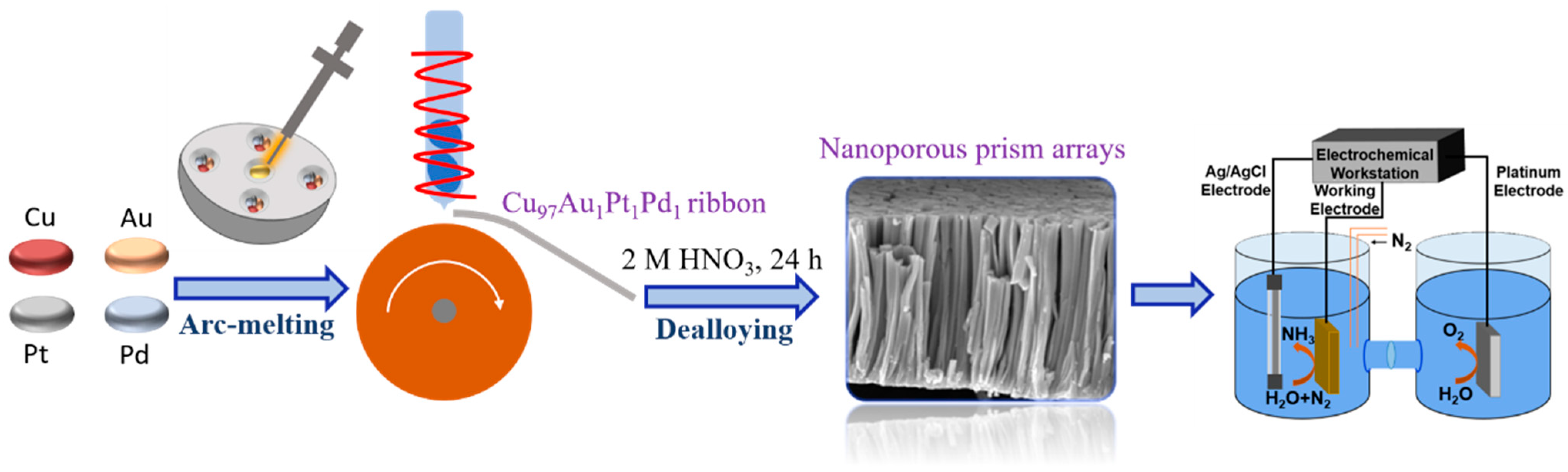
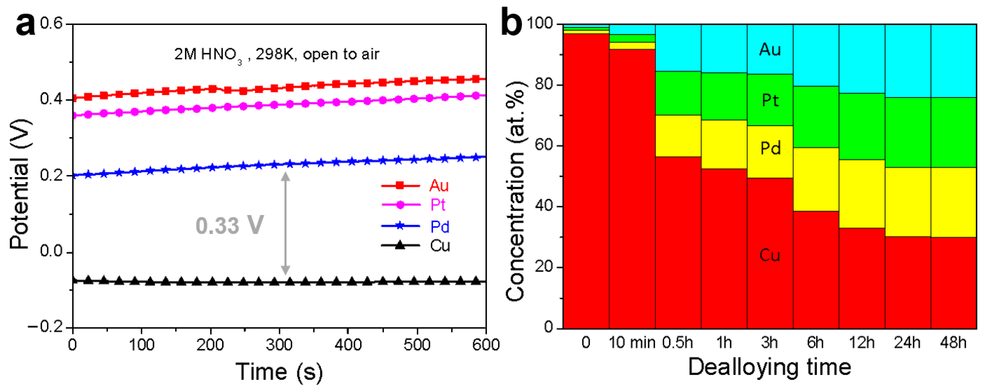
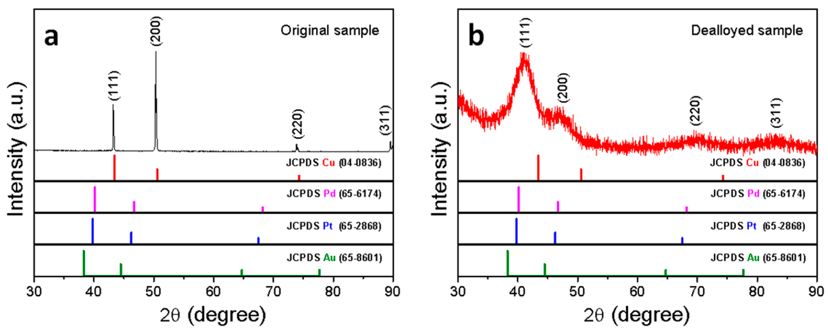
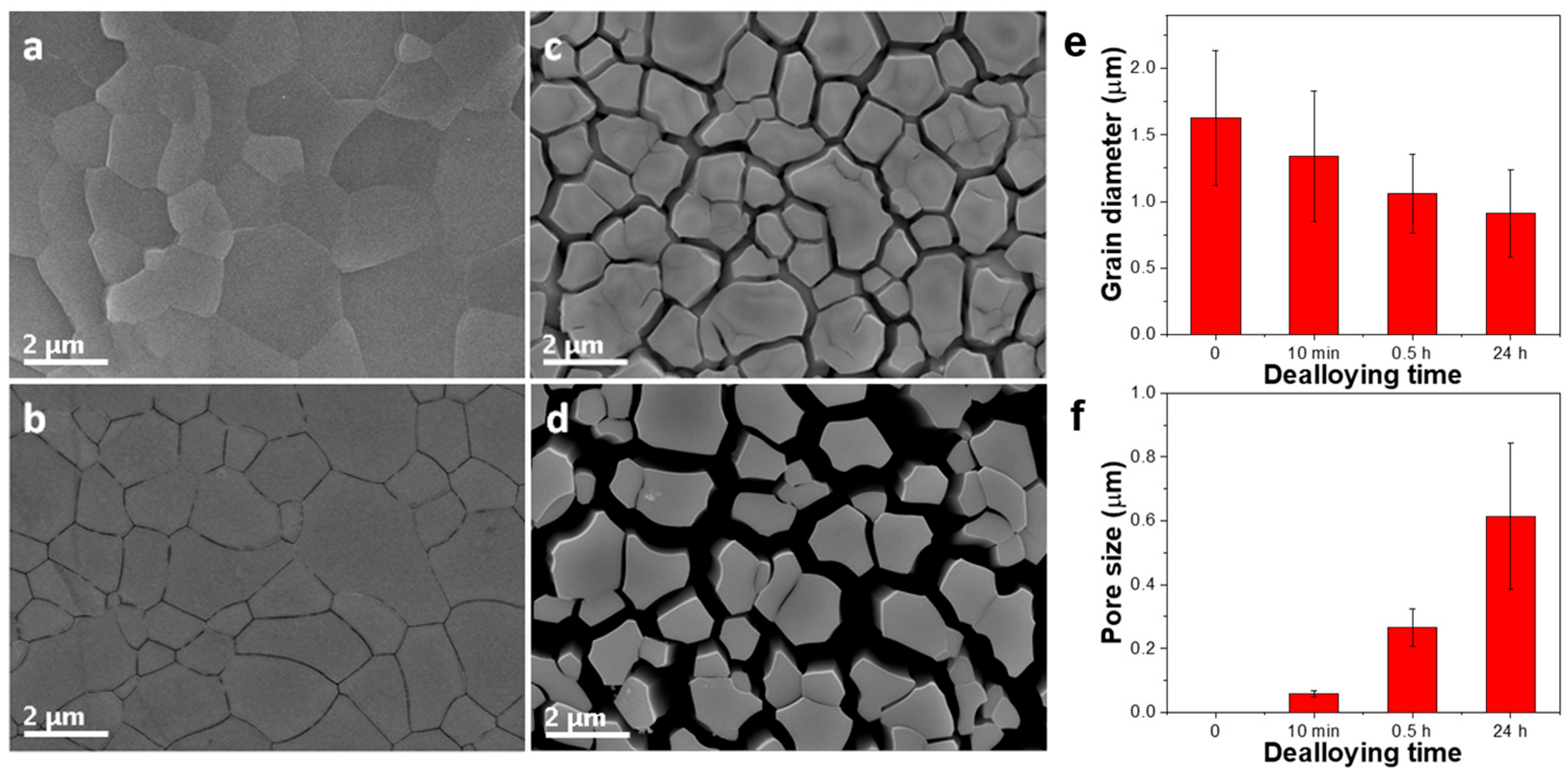
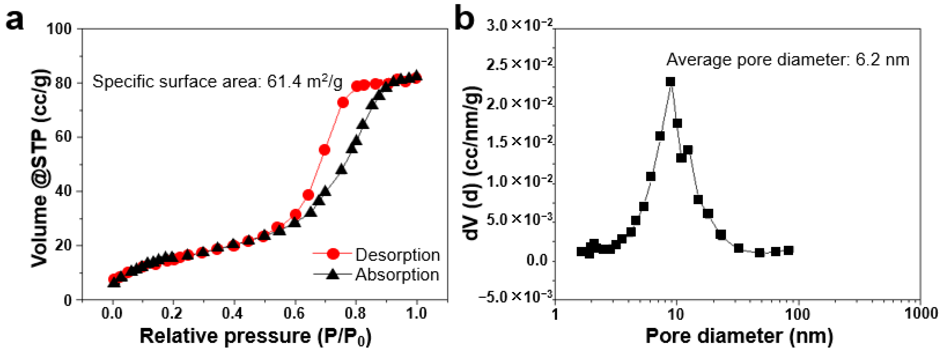
3.1. Fabrication and Characterization of np-CuAuPtPd-1

Open-circuit potentials (OCPs) of componential metals were measured using a three-electrode electrochemical system. As shown in Figure 2a, the OCPs of Cu, Pd, Pt, and Au in 2 M HNO3 solution are −80 mV, 250 mV, 410 mV, and 460 mV (vs. Ag/AgCl), respectively. These results indicate that Au, Pt, and Pd exhibit higher electrochemical stability than Cu, whereas Cu demonstrates significantly high electrochemical activity in the current condition. Notably, the potential difference between the precious metal Pd (250 mV) and the active metal Cu (−80 mV) is around 330 mV, providing a strong dynamic driving force for the preferential removal of Cu during dealloying.
To systematically analyze the effect of dealloying duration on chemical composition, the precursors were immersed in 2 M HNO3 for 10 min, 0.5 h, 1 h, 3 h, 6 h, 12 h, 24 h, and 48 h, respectively. The atomic ratios (based on energy disperse spectroscopy (EDS) results) of constituent elements (Cu, Au, Pt, Pd) at each timepoint are summarized in Figure 2. During the initial 10 min of dealloying, only marginal Cu dissolution (~5% reduction) was detected. Upon extending the dealloying time to 0.5 h, rapid Cu removal can be found. Further increases in dealloying duration (1–48 h) result in progressively slower Cu dissolution kinetics. In this case, the proportion of Cu gradually decreases, while the proportion of other precious metal elements slowly increases. Finally, no obvious compositional changes are observed between 24 h and 48 h, indicating that dynamic equilibrium is obtained. Consequently, 24 h is identified as the optimal dealloying time for achieving compositionally stable nanoporous structures.
EDS analysis of the precursor strip (Figure S1a) reveals a composition of Cu96.9Au1.0Pt1.0Pd1.1, closely matching the target stoichiometry (Cu97Au1Pt1Pd1). After dealloying, the np-CuAuPtPd-1 exhibits a refined composition of Cu34.5Au20.9Pt19.3Pd25.3 (Figure S1b, Table 1), satisfying the atomic percentage criterion for HEAs (5–35% per element). The physical parameters of the experimental materials and other previously reported HEAs are listed in Table S1. It can be found that the composition of the two experimental materials satisfies the empirical rules for the formation of HEAs, while the reduced mixing entropy (ΔSmix = 1.2 R; R is the gas constant) falls below the conventional HEA threshold (ΔSmix ≥ 1.5 R). Therefore, the material synthesized in this article should be more accurately referred to as quasi-HEAs. The identification of quasi-HEAs is stated in Supplementary S2.
The solid solution phase structure of np-CuAuPtPd-1 was confirmed via X-ray diffraction (XRD). Figure 3 shows the XRD patterns of the precursor ribbon and the dealloyed np-CuAuPtPd-1. The ribbon (Figure 3a) exhibits four sharp diffraction peaks indexed to the (111), (200), (220), and (311) crystallographic planes of a face-centered cubic (FCC) solid solution. The peak positions align closely with pure Cu (PDF #04−0836), consistent with the high Cu content (~97 at.%) of the original sample. After dealloying, np-CuAuPtPd-1 (Figure 3b) retains an FCC structure, as evidenced by broadened peaks at 41.3°, 46.9°, 69.8°, and 83.3°, corresponding to the (111), (200), (220), and (311) planes, respectively. Apart from these four peaks, no other phase peaks were found, elucidating the solid solution structure of the dealloyed material. So, only after removing solvent Cu can we see the broader shifted XRD alloy peaks. Similar phenomena have also been reported in other papers [53]. A uniform shift of ~1.2° toward lower angles (relative to the precursor) is observed, attributed to lattice expansion caused by the removal of Cu (atomic radius: 1.28 Å) and the retention of larger precious metals (Au: 1.44 Å; Pt: 1.39 Å; Pd: 1.37 Å). The broadened peaks suggest a multiphase solid solution structure potentially comprising Au-rich, Pt-rich, Pd-rich, and Cu-rich phases, which is unlike single-phase or dual-phase HEAs reported previously.
To investigate the morphological changes during dealloying, the precursor was immersed in 2 M HNO3 for 0 min, 10 min, 0.5 h, and 24 h, respectively. Figure 4 displays the corresponding SEM images. The original precursor (Figure 4a) exhibits grains with sizes ranging from 1.1 to 3.8 μm (average: 1.6 μm). After 10 min of dealloying (Figure 4b), incipient network-like cracks form preferentially at grain boundaries, indicative of selective Cu dissolution at these high-energy regions due to enhanced corrosion kinetics and localized stress concentrations. After dealloying for 0.5 h (Figure 4c), pronounced grain boundary cracking leads to partial detachment of columnar grains (~1.1 μm), initiating a microporous structure. After 24 h (Figure 4d), the pore channels widen to ~0.6 μm, yielding an open network with retained prism array morphology. Figure 4e,f show the variation of grain diameter and pore channel size with dealloying time. With the extension of time, the atoms at the grain boundaries are continuously removed, resulting in continuously smaller grains and enlarged pore channels, and, eventually, prism arrays are formed in the direction along the crystal’s growth.
Figure 5a displays a plan-view SEM image of np-CuAuPtP-1 revealing a continuous network of pore channels along grain boundaries. These channels isolate adjacent columnar grains, resulting in a uniform micrometer-scale prism array. The cross-sectional view (Figure 5b) demonstrates alignment of the prisms parallel to the <100> crystallographic orientation with a length of ~25 μm, closely matching the original thickness of the ribbon (20–30 μm). This anisotropic microstructure arises from differential shrinkage during dealloying; transverse contraction perpendicular to <100> exceeds longitudinal contraction along <100>, driving columnar grain separation.
Transmission electron microscopy (TEM) was employed to further characterize the hierarchical porous structure of np-CuAuPtPd-1. Bright-field TEM image (Figure 5c) reveals a regular sponge morphology of individual micropillars. The enlarged TEM image (insert) uncovers a bicontinuous network containing nanoscale ligaments and pores (<10 nm). The micron-sized pores (interconnected channels along grain boundaries formed by the separation of columnar grains during dealloying) and nanopores (ligament–pore structures (<10 nm) resulting from localized Cu dissolution) jointly contribute to the formation of the hierarchical porous structure of np-CuAuPtPd-1.
Selected-area electron diffraction (SAED), shown in Figure 5d, can be generalized to the diffraction of (111), (200), (220), and (311) of the FCC structure rather than the diffraction of individual Au, Pt, Pd, or Cu elements. High-resolution TEM images (Figure 5e,f) reveal compositional heterogeneity within the ligaments. Locally enriched regions exhibit lattice spacings of 2.34 Å (Au-rich), 2.26 Å (Pt-rich), 2.24 Å (Pd-rich), and 2.10 Å (Cu-rich), revealing enrichment regions of different elements. These nanoscale domains coexist within the FCC matrix, supporting the proposed multiphase quasi-HEA structure.
Figure S2 presents SEM images of np-CuAuPtPd-2 with different magnification ratios [49]. The material displays a sphere morphology with a diameter of 70~100 μm. Moreover, it also presents a hierarchical porous structure containing macropores along grain boundaries and nanopores among ligamental networks. By adjusting the process parameters, two kinds of nanoporous quasi-HEAs with a hierarchical porous structure were successfully synthesized. Due to different solidification conditions, the two materials show completely different macroscopic morphologies. The special pore structure makes the two materials potential catalysts.
Figure 6 and Figure S3 display the nitrogen adsorption–desorption isotherms and pore size distribution curves of np-CuAuPtPd-1 and np-CuAuPtPd-2, respectively. Both isotherms exhibit Type IV characteristics with an H1-type hysteresis loop, confirming the presence of abundant mesopores in these porous materials. The specific surface areas are calculated as 61.4 m2/g for np-CuAuPtPd-1 and 69.8 m2/g for np-CuAuPtPd-2, with the high values suggesting ample active sites that facilitate enhanced electrochemical processes. Furthermore, the pore size distribution is predominantly concentrated within 4–20 nm, demonstrating a relatively uniform mesoporous structure. This structural homogeneity is critical for ensuring consistent performance stability in the NRR. In addition, electrochemical active surface area (ECSA) measurements were performed (Table S2) on the experimental materials to evaluate the active surface area of the nanoporous quasi-HEAs using Pb underpotential deposition (UPD) following established methods [54,55]. Interestingly, np-CuAuPtPd-1 exhibits a higher ECSA (2.948 cm2) compared to np-CuAuPtPd-2 (2.153 cm2), despite the latter presenting a greater geometrical specific surface area. This apparent discrepancy suggests that while both materials feature nanoporous architectures, variations in their internal pore connectivity may significantly influence the overall electrochemically accessible surface area.

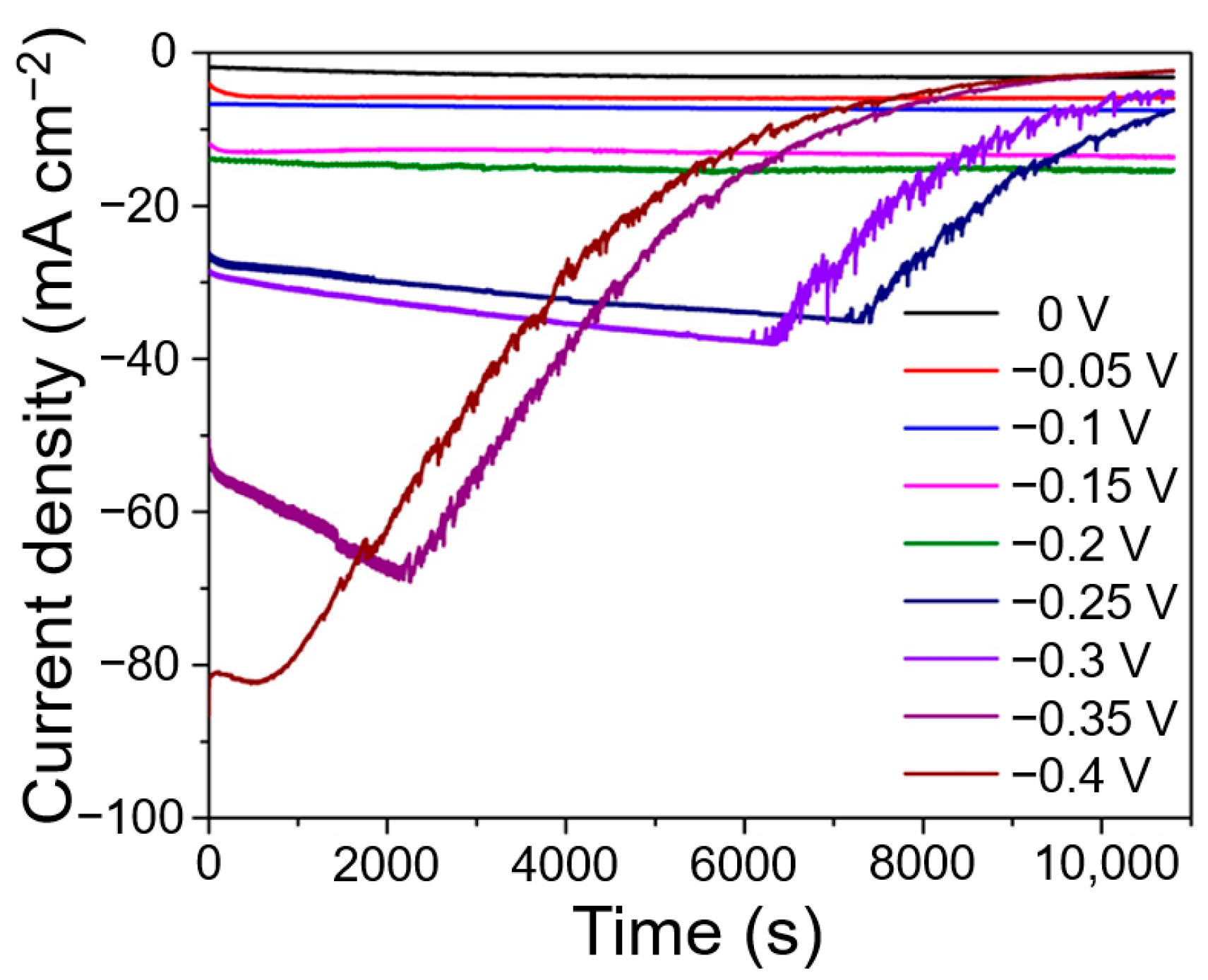
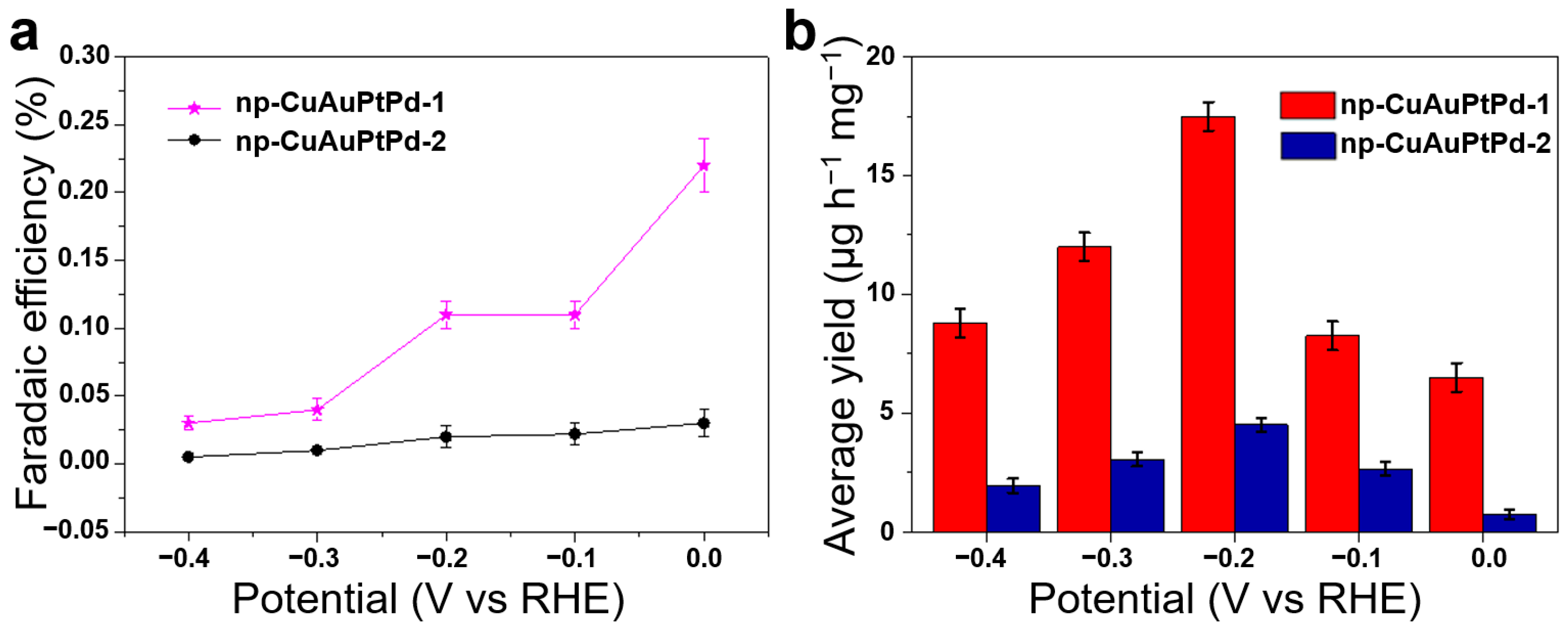
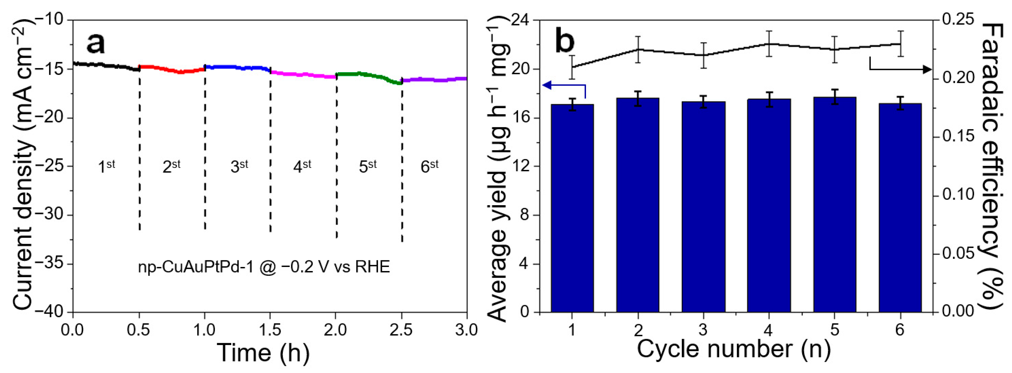
3.2. Electrocatalytic NRR Activity and Stability

To evaluate the catalytic feasibility of np-CuAuPtPd-1, composite electrodes were tested for NRR activity via chronoamperometry in 1 M KOH. Current density responses were measured across applied potentials from 0 V to −0.4 V vs. RHE (RHE is a reversible hydrogen electrode potential). As shown in Figure 7, the steady-state current density increases from 1.8 mA cm−2 at 0 V to 14.5 mA cm−2 at −0.2 V vs. RHE. Within this optimal range (0 to −0.2 V), the current density stabilizes after an initial minor decline (~5% over 10 min), demonstrating excellent electrochemical stability. With the further increase of the negative potential, the current density in the pre-catalytic reaction increases rapidly. However, as the reaction proceeds, the current density at each potential shows a great decay phenomenon, indicating that the composite electrode material could not guarantee durable and sustainable activity in this potential interval. The SEM images of the materials before and after the extended chronoamperometry experiments at −0.2 V are shown in Figure S4, revealing that the morphology of the material has not changed substantially after electrochemical tests. According to the open-circuit voltage of each element (Figure 2a), Cu together with all other elements will not be etched at −0.2 V. In this situation, the electrode after the extended chronoamperometry experiments will not experience a big change in structure or composition compared to the initial one.
Linear sweep voltammetry (LSV, Figure S5) was performed in Ar- and N2-saturated 1 M KOH electrolyte solutions. The LSV curve obtained under N2 saturation exhibits consistently higher current density across the entire potential window compared to that under Ar saturation, confirming the electrocatalytic activity of the materials toward nitrogen reduction. As evident from the figure, np-CuAuPtPd-1 exhibits HER onset potential of −0.07 V vs. RHE, while np-CuAuPtPd-2 shows a significantly more negative onset potential (−0.13 V vs. RHE), indicating that np-CuAuPtPd-2 substantially suppresses HER activity compared to np-CuAuPtPd-1.
The Faraday efficiency (FE) of np-CuAuPtPd-1 and np-CuAuPtPd-2 for NRR was evaluated across different potentials (Figure 8a). NH3 and H2 were identified as the primary products, with NH3 originating from N2 reduction and H2 arising from the competing HER. At 0 V vs. RHE, np-CuAuPtPd-1 achieves a maximum FE of NH3 of 0.22%, significantly outperforming np-CuAuPtPd-2 (0.03%). The FE of np-CuAuPtPd-1 and np-CuAuPtPd-2 is 0.11% and 0.02%, respectively, with the potential up to −0.2 V vs. RHE, indicating that np-CuAuPtPd-1 has better selectivity for NRR. The inverse correlation between FE and applied overpotential aligns with typical NRR systems, where HER dominance intensifies at higher cathodic potentials. Notably, even at optimal conditions, NH3 FE remains low (<1%), reflecting the persistent challenge of HER competition in aqueous NRR electrocatalysis.
As shown in Figure 8b, NH3 yields of np-CuAuPtPd-1 and np-CuAuPtPd-2 composite electrodes were evaluated across applied potentials. At 0 V vs. RHE, np-CuAuPtPd-1 exhibits a NH3 production rate of 6.5 μg h−1 mg−1, surpassing np-CuAuPtPd-2 (0.75 μg h−1 mg−1) by nearly an order of magnitude. The rate of NH3 synthesis increases with increasing negative potential when the potential is between 0 V vs. RHE and −0.2 V vs. RHE. When the potential reaches −0.2 V vs. RHE, the np-CuAuPtPd-1 and np-CuAuPtPd-2 composite electrode materials achieve maximum ammonia synthesis rates of 17.5 μg h−1 mg−1 and 4.5 μg h−1 mg−1, respectively. It is worth noting that the rate of NH3 synthesis of np-CuAuPtPd-1 is approximately 3.9 times higher than that of np-CuAuPtPd-2, indicating that the catalytic performance of np-CuAuPtPd-1 is significantly better than that of np-CuAuPtPd-2. With a further increase in negative potential, the NH3 synthesis rate of the np-CuAuPtPd-1 and np-CuAuPtPd-2 composite decreases significantly, which is due to the adsorption competition between nitrogen and hydrogen existing on the surface of the materials.
The cycling stability of np-CuAuPtPd-1 was evaluated via chronoamperometric tests at −0.2 V vs. RHE over six consecutive 30 min cycles (total duration: 3 h). As shown in Figure 9a, the current density remains stable (~14.5 mA cm−2) throughout all cycles, indicating negligible catalyst degradation. Furthermore, Figure 8b shows the NH3 yields and FE values of the np-CuAuPtPd-1 composite electrode measured at six cycling cycles. From Figure 9b, it can be visualized that the NH3 yield and FE values of the np-CuAuPtPd-1 remain around 17.5 μg h−1 mg−1 and 0.22% during the cycling cycles, and they still maintain nearly 100% of the original activity after 3 h of cycling, further confirming the excellent cycling stability of np-CuAuPtPd-1. This exceptional stability is attributed to the robust nanoporous architecture of np-CuAuPtPd-1, which mitigates structural collapse or active site deactivation during prolonged operation.
Table 2 lists the NH3 synthesis yield of the np-CuAuPtPd-1 composite electrode prepared in this work and materials reported in recent years [56,57,58,59,60,61]. The quasi-HEA nanoporous composite electrode material prepared in this work occupies a large performance advantage among them. The reason for this can be attributed to the porous structure and the synergistic effect among multiple components possessed by the materials. Firstly, np-CuAuPtPd-1 with porous structure has a large specific surface area, which can provide more active sites than others to promote the adsorption and transportation of reactants. In addition, the nanoporous structure has high mechanical strength and structural stability, which can maintain the original morphology and reduce the structural damage of the catalyst during the prolonged electrocatalytic reaction. Secondly, the synergistic effect of multi-metal makes the NH3 production efficiency and FE of np-CuAuPtPd-1 better than those of single-metal catalysts in NRR. Moreover, thanks to the lower activity of Cu and Au toward HER, np-CuAuPtPd-1 can effectively inhibit HER and improve the selectivity of the catalyst. Finally, the quasi-HEA structure not only enhances the structural stability of the material but also optimizes the electronic structure, which ensures the long-term durability of the catalyst during the NRR process.
When designing the composition of materials, the selection of precious metal or non-precious metal elements can be considered in this way. Due to the excellent electronic structures and surface properties, precious metals can effectively adsorb and activate inert N2 molecules, which can lower the reaction barriers and improve the NRR efficiency. However, precious metals tend to induce HER, leading to the reduction of FE, and they are scarce and expensive, making it difficult to apply them on a large scale. Some non-precious metals can inhibit HER and improve the selectivity of ammonia, and they are abundant in resources and low in price, which makes them suitable for industrial application. However, their stability is not sufficient, and their catalytic activity is far less than that of precious metals. We designed and synthesized np-CuAuPtPd based on the precious metals Au, Pt, and Pd and the non-precious metal Cu. The atomic share of Cu is as high as 97%, effectively reducing the cost of the material. In addition, np-CuAuPtPd can not only exhibit the good catalytic activity of the noble metals Au, Pt, and Pd and the inhibitory effect of the non-precious metal Cu on HER but also finally form a quasi-HEA structure to realize the synergistic effect between elements.
Although np-CuAuPtPd-1 exhibits an excellent NH3 yield, its Faradaic efficiency (FE) remains relatively low. This limitation may arise from several factors. (1) The inherent HER activity of Pt and Pd makes proton reduction thermodynamically and kinetically more favorable than NRR. (2) Cu and Au may weaken the N2 adsorption capacity of Pt/Pd sites, hindering N≡N bond cleavage. (3) While the nanoporous structure enhances the surface area and restricts N2 diffusion, many active sites remain underutilized. (4) The susceptibility of Cu to oxidation/dissolution under electrochemical conditions leads to active site loss, while strong NH3 adsorption may further poison catalytic surfaces. To improve FE, we propose the following strategies. First, modulating the D-band center via the incorporation of transition metals (e.g., Fe, Mo, or V) could optimize N2 adsorption energetics. Second, constructing hierarchical microporous–mesoporous–macroporous channels through tailored dealloying parameters may enhance N2 diffusion to internal active sites. Finally, applying hydrophobic coatings (e.g., polytetrafluoroethylene or carbon layers) could simultaneously enrich N2 concentration at the electrode–electrolyte interface, shield H+ access to active sites, and stabilize Cu against oxidative dissolution. Further development along these directions is expected to systematically enhance NRR performance.

4. Conclusions

In this work, we demonstrate the synthesis of nanoporous CuAuPtPd quasi-HEA prism arrays via melt quenching and dealloying strategies, establishing their efficacy as durable electrocatalysts for the NRR. The hierarchical porosity of np-CuAuPtPd-1, featuring interconnected micron pores and nanoscale ligaments, provides abundant active sites while ensuring structural robustness. Coupled with multi-component synergy, the np-CuAuPtPd-1 achieves an NH3 synthesis rate of 17.5 μg h−1 mg−1 at −0.2 V vs. RHE, surpassing conventional precious metal catalysts. The quasi-HEA architecture further suppresses HER and maintains nearly 100% activity retention over six cycles, addressing the critical activity–stability trade-off in NRR electrocatalysis. This work not only highlights the potential of nanoporous quasi-HEA for sustainable NH3 synthesis but also provides a blueprint for designing multi-functional catalysts through compositional and structural engineering.

Supplementary Materials

The following supporting information can be downloaded at https://www.mdpi.com/article/10.3390/met15050568/s1. Supplementary S1: Experimental details. Supplementary S2: Identification of quasi-HEAs. Figure S1: EDS spectra of the material before and after dealloying. Figure S2: SEM images of np-CuAuPtPd-2. Figure S3: Pore feature of np-CuAuPtPd-2: (a) nitrogen adsorption–desorption isotherm; (b) pore size distribution curve. Figure S4: SEM images of np-CuAuPtPd-1 before (a) and after (b) the extended chronoamperometry experiments. Figure S5: LSV curves of (a) np-CuAuPtPd-1 and (b) np-CuAuPtPd-2 in N2-saturated and Ar-saturated 1 M KOH electrolyte at a scan rate of 5 mV s−1. Table S1: Calculated parameters of the quasi-HEA materials and other reported HEAs. Table S2: Specific surface area and electrochemically active surface area (ECSA) of the experimental materials.

Author Contributions

Conceptualization, S.H. and Z.W.; formal analysis, S.H. and Z.M.; investigation, S.H. and Z.M.; resources, W.Z.; data curation, Z.M. and W.Z.; writing—original draft, S.H. and Z.M.; writing—review and editing, Z.W.; visualization, W.Z. and Z.W.; supervision, W.Z. and Z.W.; funding acquisition, S.H. and Z.W. All authors have read and agreed to the published version of the manuscript.

Funding

This study was financially supported by the Tianjin Municipal Science and Technology Program, China (24YDTPJC00780), and the Natural Science Foundation of Hebei Province, China (E2023202253).

Data Availability Statement

The original contributions presented in this study are included in the article/Supplementary Materials. Further inquiries can be directed to the corresponding authors.

Conflicts of Interest

The authors declare no conflicts of interest.

References

  1. Kang, L.W.; Pan, W.G.; Zhang, J.K.; Wang, W.H.; Tang, C.W. A review on ammonia blends combustion for industrial applications. Fuel 2023, 332, 126150. [Google Scholar] [CrossRef]
  2. Xu, P.; Li, G.; Zheng, Y.; Fung, J.C.H.; Chen, A.P.; Zeng, Z.Z.; Shen, H.Z.; Hu, M.; Mao, J.F.; Zheng, Y.; et al. Fertilizer management for global ammonia emission reduction. Nature 2024, 626, 792–798. [Google Scholar] [CrossRef] [PubMed]
  3. Cui, Y.; Ouyang, W.; Gao, A.; Yu, C.; Zhang, L. Promoting electrocatalytic nitrogen reduction to ammonia via dopant boron on two-dimensional materials. Rare Met. 2024, 43, 5117–5125. [Google Scholar] [CrossRef]
  4. Wu, X.; Tang, L.; Si, Y.; Ma, C.; Zhang, P.; Yu, J.; Liu, Y.; Ding, B. Smart interfacing between Co-Fe layered double hydroxide and graphitic carbon nitride for high-efficiency electrocatalytic nitrogen reduction. Energy Environ. Mater. 2023, 6, e12316. [Google Scholar] [CrossRef]
  5. He, Y.; Liu, S.; Wang, M.; Cheng, Q.; Ji, H.; Qian, T.; Yan, C. Advanced in situ characterization techniques for direct observation of gas-involved electrochemical reactions. Energy Environ. Mater. 2023, 6, e12552. [Google Scholar] [CrossRef]
  6. Wang, Z.F.; Wang, H.Y.; Liu, X.L.; Chen, Y.X.; Zhao, Y.; Zhang, Y.G.; Han, Q.Q.; Qin, C.L.; Bakenov, Z.; Wang, Y.C.; et al. Single Zn atoms anchored on hollow carbon nanofiber network for dendrite-free lithium metal anode of flexible Li-S full cell. Rare Met. 2023, 42, 3705–3717. [Google Scholar] [CrossRef]
  7. Awad, O.I.; Zhou, B.; Harrath, K.; Kadirgama, K. Characteristics of NH3/H2 blend as carbon-free fuels: A review. Int. J. Hydrogen Energy 2023, 48, 38077–38100. [Google Scholar] [CrossRef]
  8. Yin, Z.; Li, Y.; Ye, Y.; Liu, Y.; Li, M.; Yang, Z.; Zheng, X.; Wang, H.; Wang, Y.; Deng, Y. Sp/sp2 carbon ratio-driven high-throughput screening of electrocatalytic nitrogen reduction performance on transition metal single-atom catalysts. Rare Met. 2024, 43, 5781–5791. [Google Scholar] [CrossRef]
  9. Zhao, K.; Wang, J.; Yang, Y.; Wang, X. Efficient electrocatalytic ammonia synthesis via theoretical screening of titanate nanosheet-supported single-atom catalysts. Materials 2024, 17, 2239. [Google Scholar] [CrossRef]
  10. Kojima, Y. Hydrogen storage materials for hydrogen and energy carriers. Int. J. Hydrogen Energy 2019, 44, 18179–18192. [Google Scholar] [CrossRef]
  11. Asif, M.; Bibi, S.S.; Ahmed, S.; Irshad, M.; Hussain, M.S.; Zeb, H.; Khan, M.K.; Kim, J. Recent advances in green hydrogen production, storage and commercial-scale use via catalytic ammonia cracking. Chem. Eng. J. 2023, 473, 145381. [Google Scholar] [CrossRef]
  12. Dong, G.; Huang, C.; Chen, F.; Liu, X.; Li, Z.; Su, X.; Zeng, T.; Chen, Y.; Chen, Y.; Wang, Y. Construction of electron rich Fe active sites by FeCu alloy anchoring on carbon nitride for photocatalytic nitrogen reduction. Rare Met. 2024, 43, 1570–1579. [Google Scholar] [CrossRef]
  13. Erfani, N.; Baharudin, L.; Watson, M. Recent advances and intensifications in Haber-Bosch ammonia synthesis process. Chem. Eng. Process 2024, 204, 109962. [Google Scholar] [CrossRef]
  14. Padinjarekutt, S.; Li, H.Z.; Ren, S.J.; Ramesh, P.; Zhou, F.L.; Li, S.G.; Belfort, G.; Yu, M. Na plus -gated nanochannel membrane for highly selective ammonia (NH3) separation in the Haber-Bosch process. Chem. Eng. J. 2023, 454, 139998. [Google Scholar] [CrossRef]
  15. Bianchi, F.R.; Bosio, B. Modelling of green ammonia production based on solid oxide cells as electrolyser and oxygen separator for Haber-Bosch loop decarbonization. Int. J. Hydrogen Energy 2024, 95, 1183–1193. [Google Scholar] [CrossRef]
  16. Zhang, C.L.; Li, J.Y.; Chen, R.M.; Shen, S.J.; Wang, J.L.; Sun, Y.J.; Dong, F. NH3 synthesis from N1 compounds by photocatalytic technology: Promotion mechanism, reaction pathways, and efficiency evaluation criteria. ACS Catal. 2024, 14, 15721–15742. [Google Scholar] [CrossRef]
  17. Shang, S.Y.; Wang, F.Z.; Sun, Z.Y.; Qiang, C.F.; Chu, K. Electrocatalytic nitrite reduction to ammonia on isolated bismuth alloyed ruthenium. J. Energy Chem. 2025, 100, 369–376. [Google Scholar] [CrossRef]
  18. Zhou, Y.B.; Wang, M.F.; Zhang, L.F.; Li, N.J.; Qian, T.; Yan, C.L.; Lu, J.M. Quaternary medium-entropy alloy metallene with strong charge polarization for highly selective urea electrosynthesis from carbon dioxide and nitrate. ACS Nano 2025, 19, 7273–7282. [Google Scholar] [CrossRef]
  19. Yin, H.B.; Peng, Y.; Li, J.H. Electrocatalytic reduction of nitrate to ammonia via a Au/Cu single atom alloy catalyst. Environ. Sci. Technol. 2023, 57, 3134–3144. [Google Scholar] [CrossRef]
  20. Cui, Z.J.; Zhao, P.W.; Wang, H.H.; Li, C.L.; Peng, W.C.; Fan, X.B.; Liu, J.P. Molten salts etching strategy construct alloy/MXene heterostructures for efficient ammonia synthesis and energy supply via Zn-nitrite battery. Appl. Catal. B 2024, 348, 123862. [Google Scholar] [CrossRef]
  21. Huang, Z.L.; Rafiq, M.; Woldu, A.R.; Tong, Q.X.; Astruc, D.; Hu, L.S. Recent progress in electrocatalytic nitrogen reduction to ammonia (NRR). Coord. Chem. Rev. 2023, 478, 214981. [Google Scholar] [CrossRef]
  22. Shen, H.D.; Choi, C.; Masa, J.; Li, X.; Qiu, J.S.; Jung, Y.; Sun, Z.Y. Electrochemical ammonia synthesis: Mechanistic understanding and catalyst design. Chemistry 2021, 7, 1708–1754. [Google Scholar] [CrossRef]
  23. Shi, L.; Yin, Y.; Wang, S.B.; Sun, H.Q. Rational catalyst design for N2 reduction under ambient conditions: Strategies toward enhanced conversion efficiency. ACS Catal. 2020, 10, 6870–6899. [Google Scholar] [CrossRef]
  24. Liu, Q.; Xu, T.; Luo, Y.L.; Kong, Q.Q.; Li, T.S.; Lu, S.Y.; Alshehri, A.A.; Alzahrani, K.A.; Sun, X.P. Recent advances in strategies for highly selective electrocatalytic N2 reduction toward ambient NH3 synthesis. Curr. Opin. Electrochem. 2021, 29, 100766. [Google Scholar] [CrossRef]
  25. Ren, Y.W.; Yu, C.; Tan, X.Y.; Huang, H.L.; Wei, Q.B.; Qiu, J.S. Strategies to suppress hydrogen evolution for highly selective electrocatalytic nitrogen reduction: Challenges and perspectives. Energy Environ. Sci. 2021, 14, 1176–1193. [Google Scholar] [CrossRef]
  26. Wu, T.W.; Melander, M.M.; Honkala, K. Coadsorption of NRR and HER intermediates determines the performance of Ru-N4 toward electrocatalytic N2 reduction. ACS Catal. 2022, 12, 2505–2512. [Google Scholar] [CrossRef]
  27. Mushtaq, M.A.; Arif, M.; Yasin, G.; Tabish, M.; Kumar, A.; Ibraheem, S.; Ye, W.; Ajmal, S.; Zhao, J.; Li, P.Y.; et al. Recent developments in heterogeneous electrocatalysts for ambient nitrogen reduction to ammonia: Activity, challenges, and future perspectives. Renew. Sustain. Energy Rev. 2023, 176, 113197. [Google Scholar] [CrossRef]
  28. Chen, G.F.; Ren, S.Y.; Zhang, L.L.; Cheng, H.; Luo, Y.R.; Zhu, K.H.; Ding, L.X.; Wang, H.H. Advances in electrocatalytic N2 reduction-strategies to tackle the selectivity challenge. Small Methods 2019, 3, 1800337. [Google Scholar] [CrossRef]
  29. Yang, Y.J.; Wang, S.Q.; Wen, H.M.; Ye, T.; Chen, J.; Li, C.P.; Du, M. Nanoporous gold embedded ZIF composite for enhanced electrochemical nitrogen fixation. Angew. Chem. Int. Ed. 2019, 58, 15362–15366. [Google Scholar] [CrossRef]
  30. Yao, Y.; Zhu, S.Q.; Wang, H.J.; Li, H.; Shao, M.H. A spectroscopic study on the nitrogen electrochemical reduction reaction on gold and platinum surfaces. J. Am. Chem. Soc. 2018, 140, 1496–1501. [Google Scholar] [CrossRef]
  31. Pang, F.; Wang, F.; Yang, L.; Wang, Z.; Zhang, W. Hierarchical nanoporous Pd1Ag1 alloy enables efficient electrocatalytic nitrogen reduction under ambient conditions. Chem. Commun. 2019, 55, 10108–10111. [Google Scholar] [CrossRef] [PubMed]
  32. Mao, Q.; Li, C.; Tian, W.; Zhou, T.; Xu, Y.; Wang, Z.; Li, X.; Wang, L.; Wang, H. Modulating surface electronic structure of mesoporous Rh nanoparticles by Se-doping for enhanced electro chemical ammonia synthesis. J. Electroanal. Chem. 2022, 904, 115874. [Google Scholar] [CrossRef]
  33. Hsu, U.S.; Hung, U.D.; Yeh, J.W.; Chen, S.K.; Huang, Y.S.; Yang, C.C. Alloying behavior of iron, gold and silver in AlCoCrCuNi-based equimolar high-entropy alloys. J. Mater. Sci. Eng. A 2007, 460, 403–408. [Google Scholar] [CrossRef]
  34. Lu, Y.P.; Gao, X.Z.; Jiang, L.; Chen, Z.; Wang, T.; Jie, J.; Kang, H.; Zhang, Y.; Guo, S.; Ruan, H.; et al. Directly cast bulk eutectic and near-eutectic high entropy alloys with balanced strength and ductility in a wide temperature range. Acta Mater. 2017, 124, 143–150. [Google Scholar] [CrossRef]
  35. Zhang, Y.; Zhou, Y.J.; Lin, J.P.; Chen, G.L.; Liaw, P.K. Solid-solution phase formation rules for multi-component alloys. Adv. Eng. Mater. 2008, 10, 534–538. [Google Scholar] [CrossRef]
  36. Fan, X.Y.; Xie, L.S.; Liang, J.; Ren, Y.C.; Zhang, L.C.; Yue, L.C.; Li, T.S.; Luo, Y.L.; Li, N.; Tang, B.; et al. In situ grown Fe3O4 particle on stainless steel: A highly efficient electrocatalyst for nitrate reduction to ammonia. Nano Res. 2022, 15, 3050–3055. [Google Scholar] [CrossRef]
  37. Ma, B.Y.; Zhao, H.T.; Li, T.S.; Liu, Q.; Luo, Y.S.; Li, C.B.; Lu, S.Y.; Asiri, A.M.; Ma, D.W.; Sun, X.P. Iron-group electrocatalysts for ambient nitrogen reduction reaction in aqueous media. Nano Res. 2021, 14, 555–569. [Google Scholar] [CrossRef]
  38. Xu, Y.; Ren, K.L.; Ren, T.L.; Wang, M.Z.; Wang, Z.Q.; Li, X.N.; Wang, L.; Wang, H.J. Ultralow-content Pd in-situ incorporation mediated hierarchical defects in corner-etched Cu2O octahedra for enhanced electrocatalytic nitrate reduction to ammonia. Appl. Catal. B 2022, 306, 121094. [Google Scholar] [CrossRef]
  39. Qiu, W.B.; Xie, X.Y.; Qiu, J.D.; Fang, W.H.; Liang, R.P.; Ren, X.; Ji, X.Q.; Cui, G.W.; Asiri, A.M.; Cui, G.L.; et al. High-performance artificial nitrogen fixation at ambient conditions using a metal-free electrocatalyst. Nat. Commun. 2018, 9, 3485. [Google Scholar] [CrossRef]
  40. Zhao, S.L.; Lu, X.Y.; Wang, L.Z.; Gale, J.; Amal, R. Carbon-based metal-free catalysts for electrocatalytic reduction of nitrogen for synthesis of ammonia at ambient conditions. Adv. Mater. 2019, 31, 1805367. [Google Scholar] [CrossRef]
  41. Balaji, V.; Xavior, M.A. Development of high entropy alloys (HEAs): Current trends. Heliyon 2024, 10, e26464. [Google Scholar]
  42. Wu, C.H.; Jin, M.H.; Guo, D.Y.; Wu, L.H.; Wang, C.; Chen, X.; Wang, S. Recent development and future perspectives of high entropy alloys for catalysts. Adv. Mater. 2023, 7, 2300192. [Google Scholar] [CrossRef]
  43. Ren, J.T.; Chen, L.; Wang, H.Y.; Yuan, Z.Y. High-entropy alloys in electrocatalysis: From fundamentals to applications. Chem. Soc. Rev. 2023, 52, 8319–8373. [Google Scholar] [CrossRef]
  44. Wang, Y.X.; Zhang, Y.; Xing, P.Y.; Li, X.Q.; Du, Q.Y.; Fan, X.Q.; Cai, Z.B.; Yin, R.; Yao, Y.G.; Gan, W.T. Self-encapsulation of high-entropy alloy nanoparticles inside carbonized wood for highly durable electrocatalysis. Adv. Mater. 2024, 36, 2402391. [Google Scholar] [CrossRef]
  45. Han, X.; Wu, G.; Zhao, S.Y.; Guo, J.J.; Yan, M.Y.; Hong, X.; Wang, D.S. Nanoscale high-entropy alloy for electrocatalysis. Matter 2023, 6, 1717–1751. [Google Scholar] [CrossRef]
  46. Mu, J.; Zhao, Z.; Gao, X.W.; Liu, Z.M.; Luo, W.B.; Sun, Z.; Gu, Q.F.; Li, F. Bimetallic PdFe3 nano-alloy with tunable electron configuration for boosting electrochemical nitrogen fixation. Adv. Energy Mater. 2024, 14, 2303558. [Google Scholar] [CrossRef]
  47. Lu, X.; Li, J.; Liu, F.; Wang, Y.; Tang, X.; Li, H.; Peng, Y.; Xu, C. Powerful orbital hybridization of copper-silver bimetallic nanosheets for electrocatalytic nitrogen reduction to ammonia. Inorg. Chem. 2023, 62, 12148–12156. [Google Scholar] [CrossRef]
  48. Pang, F.J.; Wang, Z.F.; Zhang, K.; He, J.; Zhang, W.Q.; Guo, C.X.; Ding, Y. Bimodal nanoporous Pd3Cu1 alloy with restrained hydrogen evolution for stable and high yield electrochemical nitrogen reduction. Nano Energy 2019, 58, 834–841. [Google Scholar] [CrossRef]
  49. Yang, L.Z.; Li, Y.Y.; Wang, Z.F.; Zhao, W.M.; Qin, C.L. Nanoporous quasi-high-entropy alloy microspheres. Metals 2019, 9, 345. [Google Scholar] [CrossRef]
  50. Ding, J.; Zhang, L.; Wei, Z.; Wang, Z.; Liu, Q.; Hu, G.; Luo, J.; Liu, X. Coupling nitrate-to-ammonia conversion and sulfion oxidation reaction over hierarchical porous spinel MFe2O4 (M=Ni, Co, Fe, Mn) in wastewater. Small 2025, 21, 2411317. [Google Scholar] [CrossRef]
  51. Dong, L.; Luo, C.; Wang, Y.; Meng, S.; Yu, H.; Zhao, W.; Qin, C.; Wang, Z. Prelithiation enhanced initial Coulombic efficiency and cycling stability of spinel (FeCoCrNiMn)3O4 high entropy oxide anode. J. Energy Storage 2024, 98, 113185. [Google Scholar] [CrossRef]
  52. Mi, C.; Wang, Z.; Yang, S.; Liu, X.; Wang, Y.; Wang, Z. Porous Al11Ce3 intermetallics as effective sulphur host networks for stable lithium–sulphur batteries. J. Mater. Chem. C 2025, 13, 9014–9026. [Google Scholar] [CrossRef]
  53. Jin, Z.; Lv, J.; Jia, H.; Liu, W.; Li, H.; Chen, Z.; Lin, X.; Xie, G.; Liu, X.; Sun, S.; et al. Nanoporous Al-Ni-Co-Ir-Mo high-entropy alloy for record-high water splitting activity in acidic environments. Small 2019, 15, 1904180. [Google Scholar] [CrossRef] [PubMed]
  54. Noh, H.; Park, Y.; Bhadouria, A.; Tackett, B. Effects of electrochemical active surface area of Cu on electrochemical CO reduction in acidic electrolyte using Cu nanoparticles on surfactant-treated carbon. J. Catal. 2024, 437, 115662. [Google Scholar] [CrossRef]
  55. Hochfilzer, D.; Tiwari, A.; Clark, E.; Bjørnlund, A.; Maagaard, T.; Horch, S.; Seger, B.; Chorkendorff, I.; Kibsgaard, J. In situ analysis of the facets of Cu-based electrocatalysts in alkaline media using Pb underpotential deposition. Langmuir 2022, 38, 1514–1521. [Google Scholar] [CrossRef]
  56. Wang, J.; Jiang, Z.; Peng, G.; Hoenig, E.; Yan, G.; Wang, M.; Liu, Y.; Du, X.; Liu, C. Surface valence state effect of MoO2+x on electrochemical nitrogen reduction. Adv. Sci. 2022, 9, 2104857. [Google Scholar] [CrossRef]
  57. Wang, Y.C.; Ma, Z.Z.; Liu, K.; Yang, X.W.; Wang, J.X.; Wang, X.G. Rigid anchoring of highly crystallized and uniformly dispersed Pd nanocrystals on carbon fibers for ambient electrocatalytic reduction of nitrogen to ammonia. Dalton Trans. 2021, 50, 6975–6981. [Google Scholar] [CrossRef]
  58. Wan, Y.C.; Zheng, M.Y.; Lv, R.T. Rational design of Mo2C nanosheets anchored on hierarchically porous carbon for boosting electrocatalytic N2 reduction to NH3. Mater. Today Energy 2023, 32, 101240. [Google Scholar] [CrossRef]
  59. Yan, Y.; Qu, H.J.; Zheng, X.N.; Zhao, K.X.; Li, X.X.; Yao, Y.; Liu, Y. Amorphous core/shell Ti-doped SnO2 with synergistically improved N2 adsorption/activation and electrical conductivity for electrochemical N2 reduction. Chin. Chem. Lett. 2022, 33, 4655–4658. [Google Scholar] [CrossRef]
  60. Wang, Z.Q.; Dai, Z.C.; Wang, S.Q.; Zhang, H.A.; Tian, W.J.; Xu, Y.; Li, X.I.; Wang, L.; Wang, H.J. Enhancing electrochemical ammonia synthesis on palladium nanorods through surface hydrogenation. Chem. Eng. J. 2021, 416, 129105. [Google Scholar] [CrossRef]
  61. Lu, X.Y.; Li, H.; Wang, Y.T.; Huang, J.F.; Xu, C.L. Amorphous ReS2 decorated TiO2 nanowire arrays for highly-efficient nitrogen reduction. Chem. Commun. 2021, 57, 6023–6026. [Google Scholar] [CrossRef] [PubMed]
Figure 1. The preparation process of np-CuAuPtPd quasi-HEA prism arrays.
Metals 15 00568 g001
Figure 2. (a) Open-circuit potentials plotted versus immersion time curves for the Cu, Au, Pt, and Pd pure metals in 2 M HNO3 solution. (b) Chemical composition of the precursor after dealloying over different times in 2 M HNO3 solution at ambient temperature.
Metals 15 00568 g002
Figure 3. XRD patterns of precursor ribbons (a) before and (b) after dealloying in 2 M HNO3 solution for 24 h at ambient temperature.
Metals 15 00568 g003
Figure 4. SEM images of precursor ribbons dealloyed in 2 M HNO3 solution over different times at ambient temperature: (a) 0 min; (b) 10 min; (c) 0.5 h; (d) 24 h. Grain diameter (e) and pore size (f) at different dealloying times.
Metals 15 00568 g004
Figure 5. SEM images of precursor ribbons dealloyed in 2 M HNO3 solution for 24 h at ambient temperature: (a) plan-view, (b) section-view; TEM images of precursor ribbons dealloyed in 2 M HNO3 solution for 24 h at ambient temperature: (c) bright-field TEM image; (d) SAED pattern; (e,f) HRTEM images.
Metals 15 00568 g005
Figure 6. Pore feature of np-CuAuPtPd-1: (a) nitrogen adsorption–desorption isotherm; (b) pore size distribution curve.
Metals 15 00568 g006
Figure 7. Chronoamperometry results of np-CuAuPtPd-1 at different potentials.
Metals 15 00568 g007
Figure 8. Catalytic performance tests of np-CuAuPtPd at different potentials: (a) Faradic efficiency; (b) NH3 yields.
Metals 15 00568 g008
Figure 9. Electrocatalytic stability tests of np-CuAuPtPd-1 at −0.2 V vs. RHE for 6 consecutive periods of 0.5 h: (a) current density; (b) NH3 yields.
Metals 15 00568 g009
Table 1. Alloy composition (at.%) of the as-prepared experimental materials.
MaterialCuAuPtPd
np-CuAuPtPd-134.520.919.325.3
np-CuAuPtPd-230.222.922.024.9
Table 2. Comparison of NRR activity of np-CuAuPtPd-1 with other catalysts.
Electrocatalyst MaterialsPotential
(V vs. RHE)
NH3 Yield
(μg h−1 mg−1)
Reference
MoO2+x−0.23.95[56]
PdNCs@CNFs−0.24.4[57]
Mo2C@C−0.212.55[58]
Ti-doped SnO2−0.213.09[59]
PdH0.43NRs−0.217.53[60]
ReS2/TiO2−0.249.8[61]
np-CuAuPtPd-1−0.217.5This work
Disclaimer/Publisher’s Note: The statements, opinions and data contained in all publications are solely those of the individual author(s) and contributor(s) and not of MDPI and/or the editor(s). MDPI and/or the editor(s) disclaim responsibility for any injury to people or property resulting from any ideas, methods, instructions or products referred to in the content.

