Article

The Effect of N/O Elements on the Microstructure and Mechanical Properties of Ti-N-O Alloys

1
Key Laboratory of Advanced Technology of Materials of Education Ministry, School of Materials Science and Engineering, Southwest Jiaotong University, Chengdu 610031, China
2
Yibin Institute of Southwest Jiaotong University, Yibin 644000, China
*
Author to whom correspondence should be addressed.
Metals 2025, 15(5), 554; https://doi.org/10.3390/met15050554
Submission received: 10 April 2025 / Revised: 12 May 2025 / Accepted: 15 May 2025 / Published: 17 May 2025

Abstract

:
A novel Ti-N-O composite was prepared by powder nitriding/oxynitriding combined with the spark plasma sintering (SPS) method. The effects of N/O on the microstructure and mechanical properties of the Ti-N-O alloy were systematically studied. The results showed that the addition of N/O elements significantly improved the mechanical properties of commercially pure titanium (cp-Ti). The hardness reached 298.8 HV0.1 while the yield strength can reach 666 MPa. And, the O element played a leading role in regulating the microstructure and morphology of the Ti-N-O alloy. With the addition of the O element, the microstructure showed an equiaxed structure, and the characterization showed that this region is an O-enriched region, and that a small amount of nano-TiO2 particles appeared in the alloy, which together led to the change in the microstructure. At the same time, more large-angle grain boundaries were generated in the Ti-N-O alloy. This study investigated a new method for the preparation of titanium materials and provides new ideas for researching medical titanium materials.

Graphical Abstract

1. Introduction

Titanium and its alloys have low density, high strength, and excellent biocompatibility, along with high corrosion resistance, and are considered to be light materials. Therefore, they have been widely used in the aerospace, automobile, marine, and biomedical industries [1,2,3,4]. Commercially pure titanium (cp-Ti), in particular, is often used as an implant material to replace damaged bone or tissue [5,6,7,8,9]. However, a critical demerit of cp-Ti is its intrinsically low strength caused by its hexagonal close-packed (HCP) single-phase nature [10,11,12], which limits its applications. The ASTM standard classifies cp-Ti into four grades (1–4) based on its interstitial contents (especially oxygen). The mechanical properties of the different grades vary considerably. The yield strength (YS) of grade 4 is ~2.8 times that of grade 1, but the YS is still low (~480 MPa) [13].
In recent years, research efforts have been focused on enhancing the surface of cp-Ti in order to improve its strength. Many organic and inorganic solutions have been used for cp-Ti coating applications [14]. Mohammadi et al. performed the thermochemical gas nitriding of cp-Ti in a pure nitrogen atmosphere under a pressure of 2.5 × 10⁵ Pa at temperatures of 1123 K, 1223 K, and 1323 K for 8 h. The δ-TiNx, ε-Ti2N, TiN0.3, and α-Ti (N) phases were formed on the nitrided samples from the surface to a certain depth, sequentially, and the surface microhardnesses were 983 ± 87 HV, 1141 ± 106 HV, and 1278 ± 131 HV, respectively [15]. Körkel et al. controlled the formation of white rutile surface layers on cp-Ti by gaseous thermochemical oxidation and focused on a two-step oxidation process. The two-step oxidation process was found to result in the controlled growth of robust, dense, adherent white titanium oxide layers, and the hardness distribution in the oxide layer exhibited a plateau at 800–1000 HV0.01 [16]. Ye et al. fabricated nanoporous TiO2-TiN composite films with enhanced tribological properties on cp-Ti by combining an electropulsing-assisted ultrasonic surface rolling process (EP-USRP) and an electrochemical process. The surface hardness was increased by ~295 HV (~41.1% over the untreated sample) and the hardening depth reached ~600 μm [17]. Yaskiv et al. carried out an oxynitriding process on cp-Ti by introducing the controlled oxygen-containing medium into the system at the finishing stage of the nitriding (during cooling). The mechanical properties such as hardness were improved [18]. Although the majority of the experimental processing methods used to create these coatings have been well consolidated, some of them, such as plasma spray or sputtering, which are commonly used to deposit thick coatings and submicrometric thin coatings, may necessitate a significant investment in equipment [19]. And, the coatings cannot change the internal properties of the material.
Fang et al. added the multi-element Fe-Cr-Ni-Mo in the form of 316L steel into cp-Ti to prepare the bulk samples and achieved the simultaneous enhancement of strength and uniform ductility [20]. The in situ alloying of alloys with single elements like Cu [21] or Fe [22] has been employed to develop new alloys with promising mechanical properties. However, studies on the impact of N and O on the microstructure and mechanical properties of Ti-N-O bulk materials are scarce. Powder nitriding/oxidation is an appropriate procedure because it allows nitrogen/oxygen to diffuse to the center of the powder at a sufficiently high rate in an interstitial diffusion manner [23]. Spark plasma sintering (SPS) is a new technology for preparing functional materials. Fast and efficient sintering can be achieved under the combined action of a spark discharge, Joule heating, electrical diffusion, and plastic deformation effect in the SPS process [24,25]. SPS is characterized by uniform sintering, low grain growth, compaction–densification, and better purification. It is considered a suitable process for consolidating a wide range of powder composites with high-density and homogeneous microstructures [26]. Energy consumption during the SPS consolidation process is less than a third of that of the conventional processes [27,28].
In order to enhance the overall mechanical properties of cp-Ti, a series of Ti-N-O alloys were prepared by powder nitriding/oxynitriding combined with the SPS method, and the effects of the N and O elements on the microstructure and mechanical properties of the cp-Ti were investigated. In this study, a new alloy system has been developed, which can achieve the preparation of bulk materials by using only a simple and effective method. It also ensures that the properties of the material are enhanced. This can provide new ideas for the research of medical titanium materials.

2. Materials and Methods

2.1. Materials

The TA1 cp-Ti powder used in this study (prepared by PREP, showing good roundness, about 15–212 μm) had a composition (in mass %) of 0.150 O, 0.200 Fe, 0.030 N, 0.080 C, 0.013 H, and balance Ti. The powder nitriding and oxynitriding were used for the treatment of TA1 cp-Ti powder. The treated powder was prepared by SPS to obtain the bulk Ti-N-O alloys. The sample nomenclature and the corresponding specific process parameters are shown in Table 1. The nitriding temperature is generally chosen to be low, as a very high temperature and long duration may cause detrimental microstructural changes [29]. Liu et al. used a cathodic cage in combination with the pulsed-biased system to achieve the nitriding of TA1 titanium at a cathodic potential below 660 °C [30]. Kikuchi et al. fabricated cp-Ti with a bimodal microstructure consisting of a substrate surrounded by a network structure of the nitrogen diffusion phase by sintering nitrided powders, and demonstrated that the cp-Ti fabricated from powder nitrided at 600 °C has a higher tensile strength as well as a lower friction coefficient than compacts fabricated from as-received cp-Ti powder [31]. Based on the above, different heat treatments at 600 °C and 650 °C were selected for this study. The whole process of powder nitriding/oxynitriding was carried out in a well-type furnace under a gas atmosphere. The ammonia flow rate was maintained at 2 L/h throughout the powder nitriding process, while the air was added into the powder oxynitriding process, and the flow rate was 0.2 L/h. The Ti-N-O alloys were prepared by the SPS method. The sintering process involved heating to 1050 °C at a rate of 100 °C/min under a 30 MPa pressure, with a 10 min hold time. The final sintered cylindrical samples were each 20 mm in diameter and 15 mm in height.

2.2. Characterization Methods

The phase composition of the samples was identified by X-ray diffraction (XRD) utilizing a PANalytical Empyrean X-ray (Almelo, The Netherlands) which has a 20–80° range and a 0.02 step. The samples were applied standard processes for sandpapering and polishing and then etched in the solution of HF, HNO3, and H2O with a ratio of 2:1:17, and the corrosion time was 5 to 10 s. The surface morphology of the sample was inspected by means of an optical microscope (OM) OLYMPUS GX51 (Tokyo, Japan). The bulk density of the sintered samples was measured by Archimedes’ drainage method, and relative density was calculated by the ratio of the bulk density to the theoretical density. A JSM 7800F Prime scanning electron microscope (SEM) (JEOL, Tokyo, Japan) combining energy dispersive spectroscopy (EDS) and Oxford Symmetry S2 Electron Back-Scattered Diffraction (EBSD) (Oxford Instruments, Abingdon, UK), as well as a Thermo Scientific FEI Talos F200X (Waltham, MA, USA) transmission electron microscope (TEM) were adopted to assess the elemental distribution, chemical homogeneity, and microstructural characterization. Vickers hardness tests were performed using an HVS-1000 Vickers microhardness tester (Changzhou, China) at a load of 100 gf and a dwell time of 15 s. Compressive tests were performed using a WDW-200 universal testing machine (Shanghai, China) with a sample size with a diameter of 7.5 mm and a height of 11.25 mm at a cross-head speed of 1 mm/min.

3. Results and Discussion

3.1. Mechanical Properties

Figure 1 shows the hardness curve of the Ti-N-O samples. The load during the test is 100 g, the holding time is 15 s; 50 points are randomly selected on the test surface of the sample, and finally the average value and standard deviation are taken to obtain the hardness value and are shown as error bars in the figure. Compared with the raw sample, the hardness of the samples has been greatly improved by adding the N and O elements, and the 600-3hNO sample has the largest increase (304.3 HV0.1), which is about 125% higher than that of the raw sample. At the same time, the effect of oxynitriding for 2 h or 3 h is not very different. For bulk cp-Ti samples, many studies have been conducted on their mechanical properties. For example, Dong et al. treated sintered powder metallurgy cp-Ti by a multi-pass hot rolling process. The hardness of the obtained samples was up to 196.42 HV [32]. Zhao et al. treated ultrafine-grained cp-Ti with a large-volume equal-channel angular pressing (L-ECAP) and multi-directional forging (MDF) process. The highest hardness of the resulting samples is 281HV [33]. The hardness of the 600-3hNO sample in this study exceeded the reported hardness, proving the feasibility of this method.
Figure 2 shows the compression stress–strain curve of Ti-N-O samples. The raw sample is a very typical plastic material, and there is no failure phenomenon in the compression test. The fracture phenomenon of the other three Ti-N-O samples is obvious, as shown in Figure 3. Among them, the plasticities of the 600-3hNO and 650-3hN-2+O samples are similar, and the compressive strain is close to 0.4, but the hardness of the 650-3hN-2+O sample is the lowest. The compressive strain of the 600-2hNO samples is about 0.49, and the compressive yield strength of the 600-2hNO and 600-3hNO samples is almost the same (666 MPa and 684 MPa, respectively), while the compressive strength of the 600-2hNO sample is 282 MPa higher than that of the 600-3hNO sample (2154 MPa and 1872 MPa, respectively). Moreover, compared with the Ti-N samples prepared by the pure nitriding process, the yield strength of the 600-2hNO sample is 52 MPa higher than that of the Ti-N sample under the optimum process (the 650-3hN-2 sample), which also shows that the addition of oxygen is more obvious and efficient than nitrogen in terms of improving the strength of the sample under this experimental system. Combining hardness, compressibility, and energy saving, it is obvious that the 600-2hNO process can obtain great performance in a short time, and is the best process for preparing Ti-N-O.

3.2. Microstructure

Considering the mechanical properties of the Ti-N-O alloys, the 600-2hNO sample, which has better hardness and yield strength, and the raw sample were selected in this study for further comparative analysis of the microstructure.
Figure 4 shows the XRD patterns obtained from the 600-2hNO powder, the 600-2hNO sample, and the raw powder. The raw powder is mainly made up of the α-Ti phase. The diffraction peaks of TiO2 appeared in the 600-2hNO powder, which was attributed to the formation of TiO₂ after the oxygen content of the surface layer exceeded the solid solution limit of titanium during oxynitriding. The diffraction peaks of the 600-2hNO sample are basically the same as that of raw powder. Based on speculation, this may be due to the decomposition of TiO₂ under Joule heat, the diffusion of oxygen atoms into the low-concentration region, and the eventual formation of α-Ti solid solution containing N/O after SPS. In fact, during the whole sintering process, the sample undergoes α→β→α transformation (α phase to β phase and then α phase), which will be discussed in detail later. Figure 5 shows the SEM images of the surface of the raw powder, the 600-2hNO powder, and the 600-2hNO sample. The 600-2hNO powder presents a rougher surface than the raw powder, and some scattered bright white particles less than 1 μm in diameter can be found. Such white particles were not observed in the 600-2hNO sample either. Combined with the XRD patterns, it is inferred that these are generated TiO2 particles.
Figure 6 shows the OM images of the 600-2hNO sample and the raw sample. All the samples showed lath structures with different thicknesses, while equiaxed structures were found in the 600-2hNO sample. The relative densities of the raw and 600-2hNO samples are 97.9% and 98.1%, respectively. It can be seen that the samples obtained by SPS are almost close to being fully dense. This can also be observed in the OM images, where no obvious defects are observed. The relative densities of the raw and 600-2hNO samples are almost the same, indicating that the addition of N/O has little effect on the density. Figure 7 shows the SEM image and EDS analysis of the 600-2hNO sample. A thin strip “bump”, which is different from the morphology on both sides, is shown. Energy dispersive spectroscopy (EDS) was used to determine the composition of the different morphologies. It can be seen that the oxygen content of points A and B, which represent the bump area, is several times higher than that of point C, referring to similar work conducted by our predecessors [34]. The “bump” is the so-called α-phase reserved area, which is also the oxygen-enriched area, while the two sides represented by point C experienced the transformation from α to β and then to the α-phase during sintering. Combined with metallography, we infer that most areas experienced the transformation from α to β to α during sintering, and these boundaries different from lath structure should be solid solution element-enriched areas. Oxygen, as a stable element of the α-phase, was enriched in the local grain boundary region during sintering, which keeps the α phase from the α→β→α transformation, hinders the formation of lath morphology, and presents an equiaxed morphology, which together with the lath α phase constitutes the microstructure. In addition, the N element was not detected by the EDS, and it may be that oxygen atoms occupy most of the gaps so that the space for nitrogen atoms is small, so the O element plays a leading role in regulating the microstructure and morphology of the Ti-N-O alloy.
Figure 8a shows the TEM image of the 600-2hNO sample. The shooting area is the intersection of the precipitated phase and the matrix. The two areas in the figure, b and c, are subjected to selective Fourier transform, and the precipitated phase is determined to be nano-TiO2 particles after calibration, which corresponds to the previous discussion. The crystal plane direction and crystal plane spacing corresponding to the α-Ti phase and the selected TiO2 precipitation phase are also marked in Figure 8b,c. The (2 0–1 2) crystal plane of TiO2 and the (1 0–1 3) crystal plane of α-Ti are transformed by inverse Fourier transform, and the corresponding inverse Fourier images shown in Figure 8d,e are obtained. It can be clearly seen that there are basically no dislocations in the selected crystal plane direction in the TiO2, and only a small lattice distortion exists, which is indicated by the red arrow, while more dislocations are displayed near the α-Ti end of the TiO2 phase. Because dislocation movement is hindered by the hard phase, the atomic arrangement in the α-Ti matrix region is disordered and the Fourier facula is blurred. Another possibility is that oxygen atoms diffuse to the matrix induced by the partial decomposition of the secondary phase at a high temperature, and the concentration of oxygen near the secondary phase is high (similar to the alloy’s G-P region [35]), and the semi-coherent high solid solution region of its near-precipitation state intensifies atomic disorder due to lattice distortion.
Figure 9 shows grain boundary images of the raw sample and the 600-2hNO sample taken under EBSD. The red, green, and blue lines represent the grain boundaries with angles of 2~5°, 5~15°, and above 15°, respectively. The extrusion deformation between the powders leads to the edge breaking, and the sintering temperature rise is equivalent to recrystallization, so many dense large-angle grain boundaries appear locally after sintering. It is calculated by software that the total length of the grain boundaries in the 600-2hNO sample is not very different from that of the raw sample, but the total length of large-angle grain boundaries is 1.14 cm greater than that of the raw sample, which also proves that more large-angle grain boundaries are produced in the 600-2hNO sample after sintering.

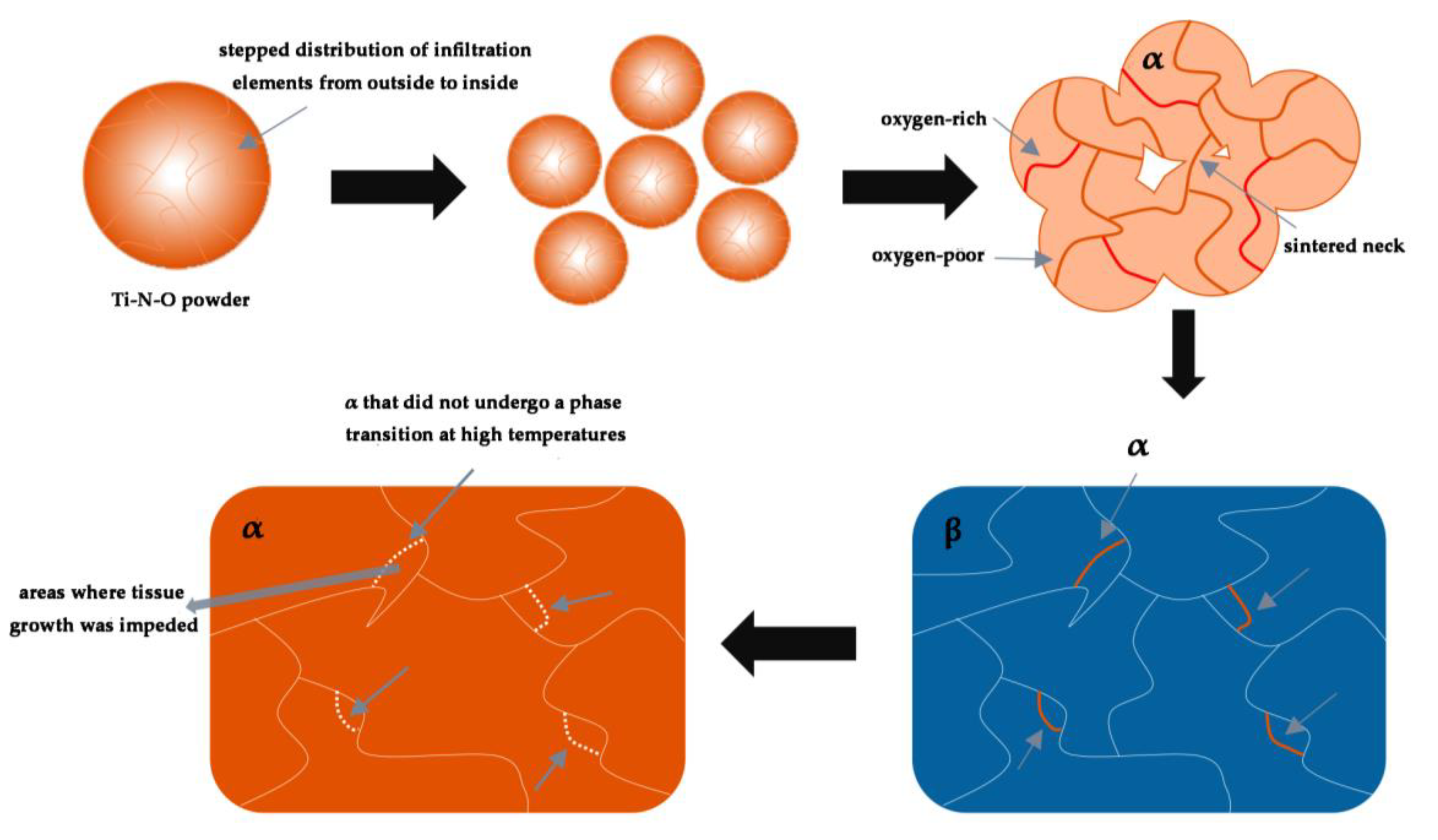
3.3. Organization Formation of Ti-N-O Alloys During Sintering

Figure 10 shows the schematic diagram of the organization growth of the Ti-N-O alloys throughout the sintering process. Firstly, powders with solid solution elements distributed in a stepwise manner from the outside to the inside are prepared. Among them, the N and O contents of each powder vary due to the different infiltration conditions of the different powders. Immediately thereafter, the prepared powders are sintered. At this point, a sintered neck starts to form between the powders. Electric current and Joule heat are transferred between the powders, and energy converges throughout the interior of the embryo. Solid solution atoms begin to migrate at this time, diffusing in all directions toward the matrix while large angular grain boundaries and regions of high deformation become their preferred destinations. Although the temperatures in all regions of the embryo have not reached the β-phase transition point, the rapid temperature increase of 150 °C/min does not leave much time for the atoms to migrate. The oxygen-poor and oxygen-rich distribution has been identified. The oxygen-rich interface is marked with a thick red line in the figure. After reaching 1100 °C, the vast majority of the α-phase inside the embryo reaches the β-phase transition point. However, a small number of oxygen-rich interfaces retain the α-phase in this small region due to the stabilizing effect of O (marked by the thick orange line in the figure). During cooling to room temperature, the transient β-phase transforms back into the α-phase, which starts to form the typical α-Ti lath shape during this process. This is hindered by the α-phase, which has not been involved in the phase transition throughout the process (marked by the white dashed line in the figure). In some places, the growth of the lath-like morphology is limited, showing an equiaxed rather than a lath-like morphology. These equiaxed organizations intersect with the surrounding lath-like organization, and ultimately make up the organization morphology of the Ti-N-O alloys.

4. Conclusions

In this work, the effects of N/O on the microstructure and mechanical properties of Ti-N-O alloys were reported. The main conclusions are as follows:
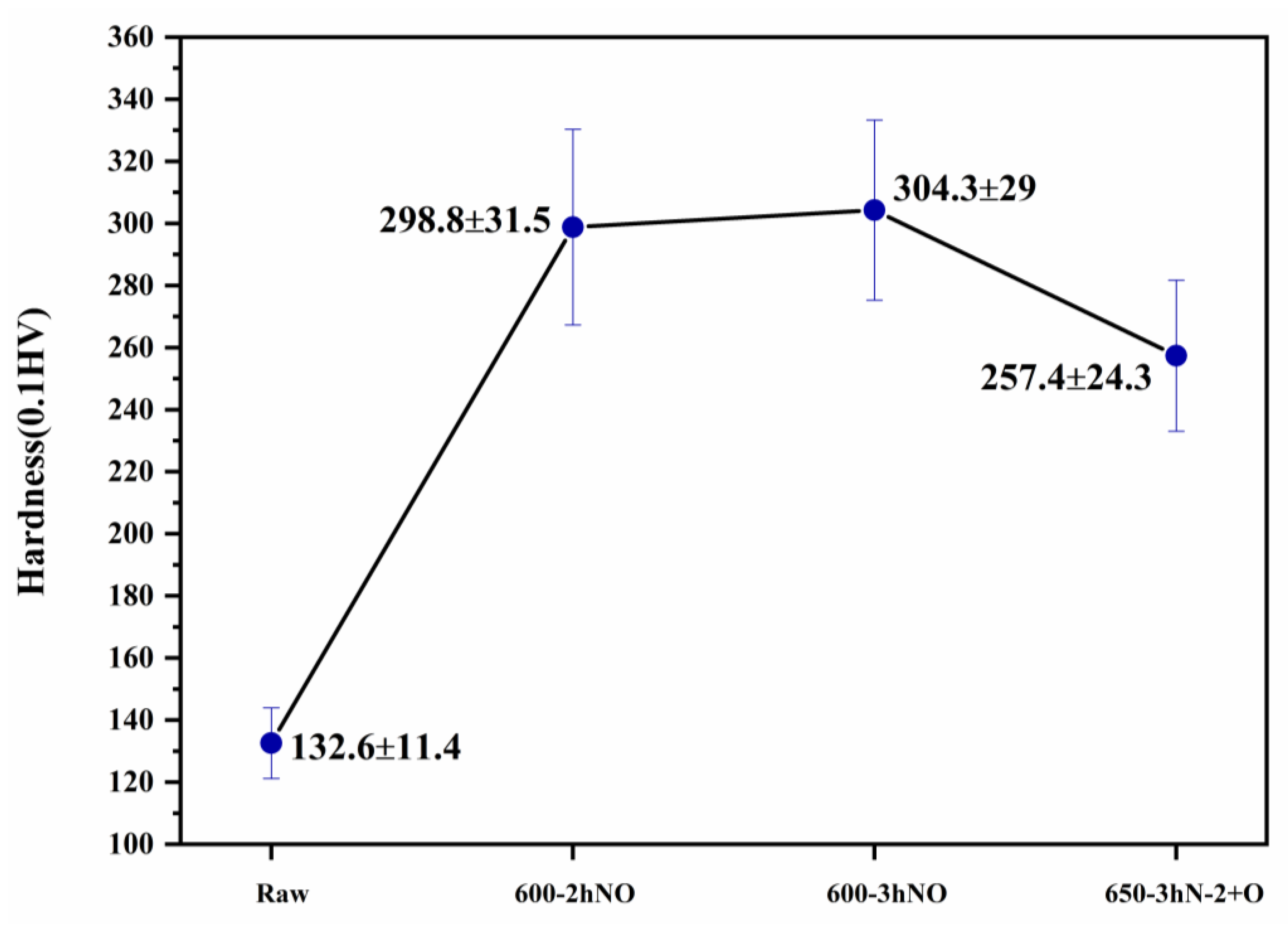
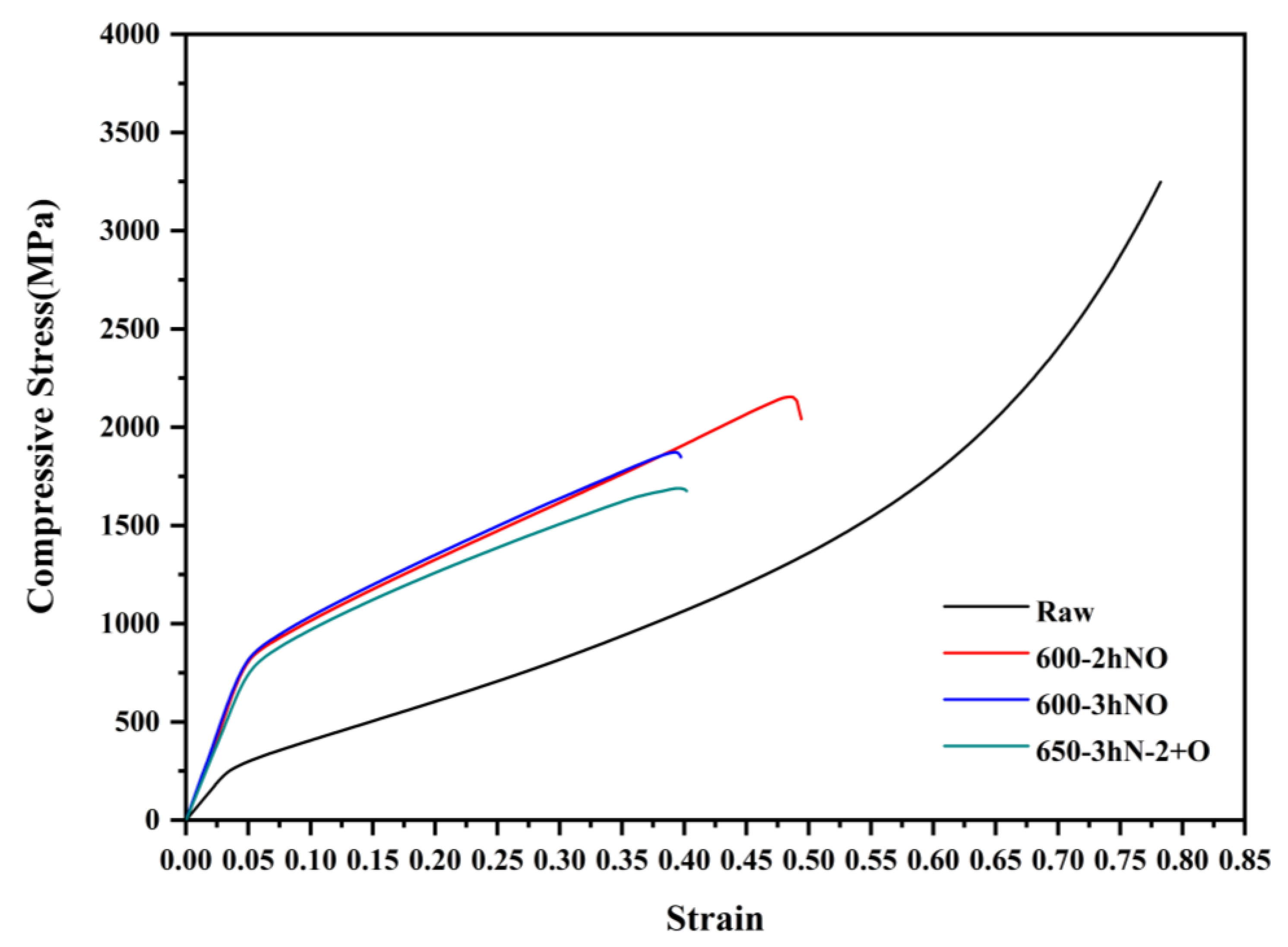
  • The yield strength of the Ti-N-O alloy prepared by powder oxynitriding at 600 °C for 2 h was 666 MPa, which was 203% higher than that of the cp-Ti, and the hardness was 298.8 HV0.1, which was 125% higher.
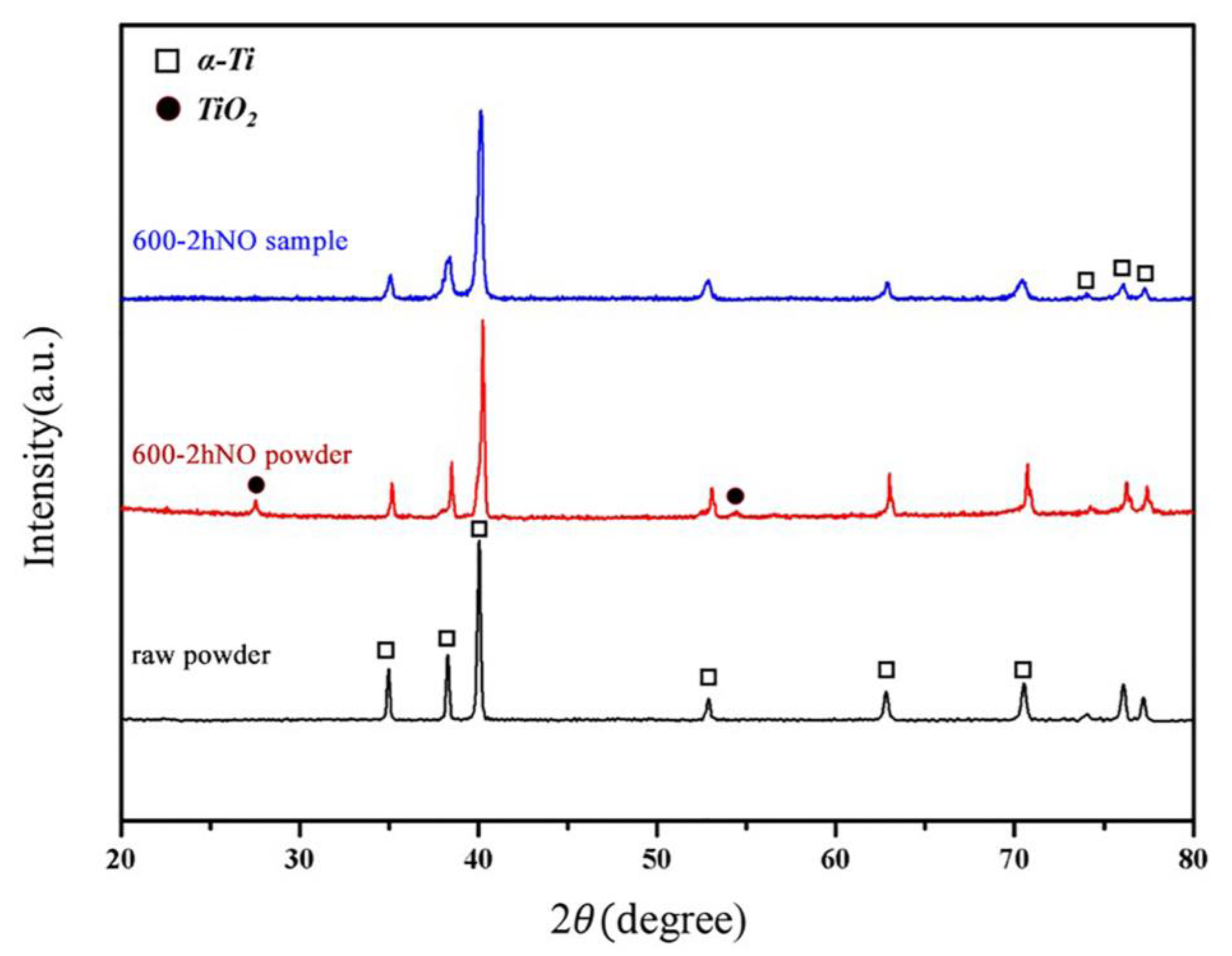
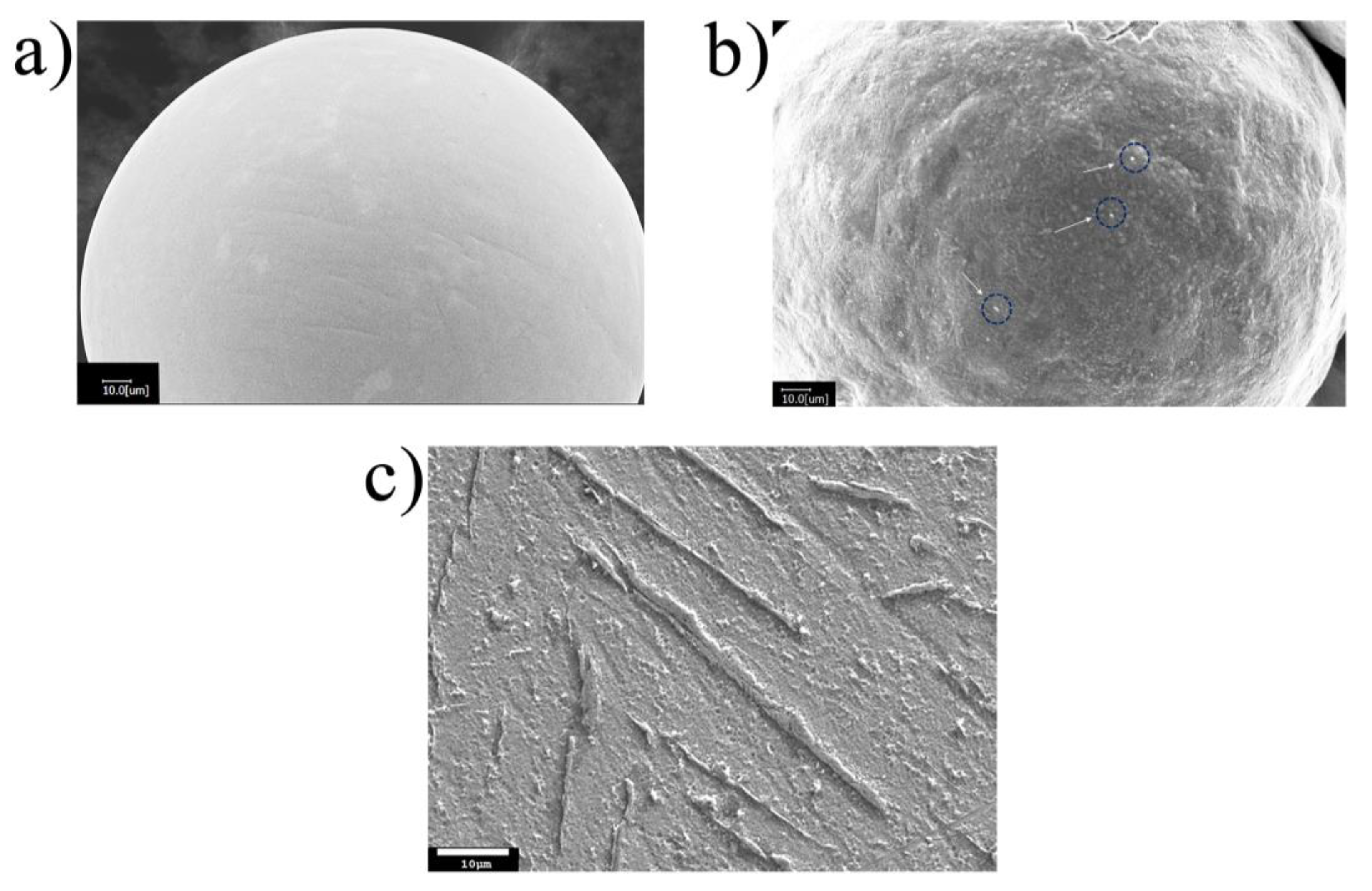
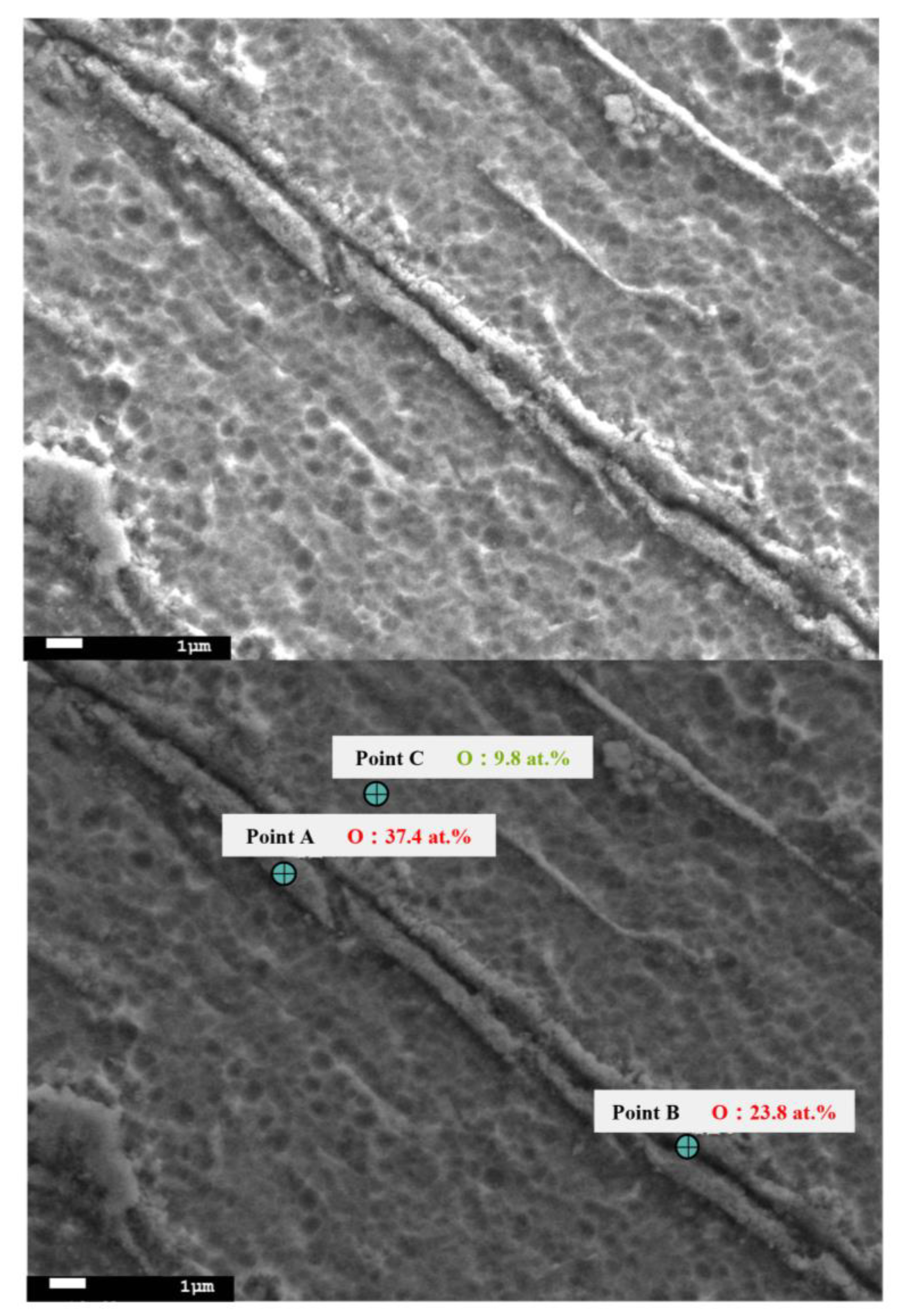
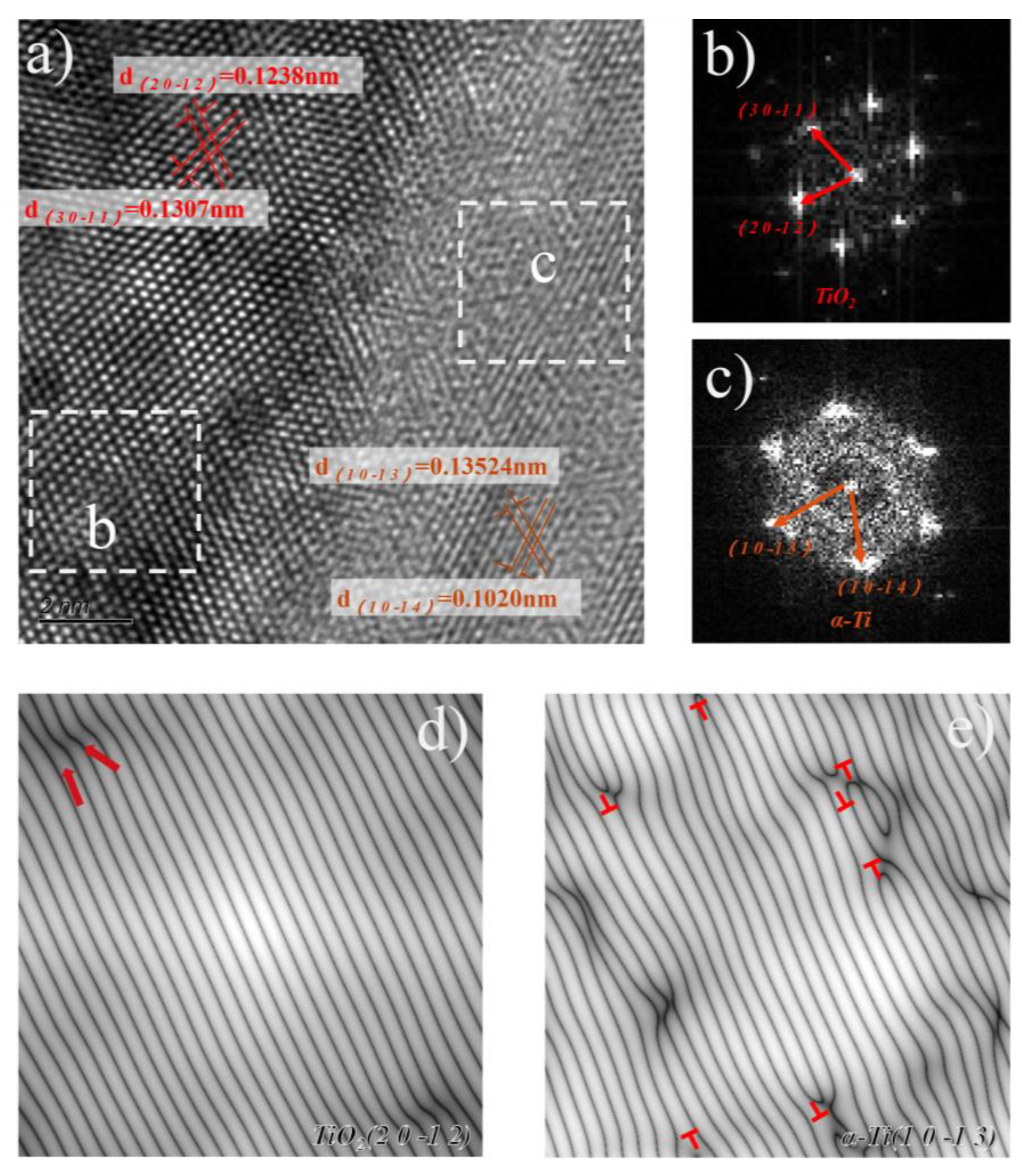
  • In the process of preparing the Ti-N-O powder, TiO2 was formed on the surface of the powders. After the powder was sintered into a bulk, TiO2 did not completely disappear, forming a second phase strengthening effect on the matrix, and a large number of dislocations could be observed nearby.
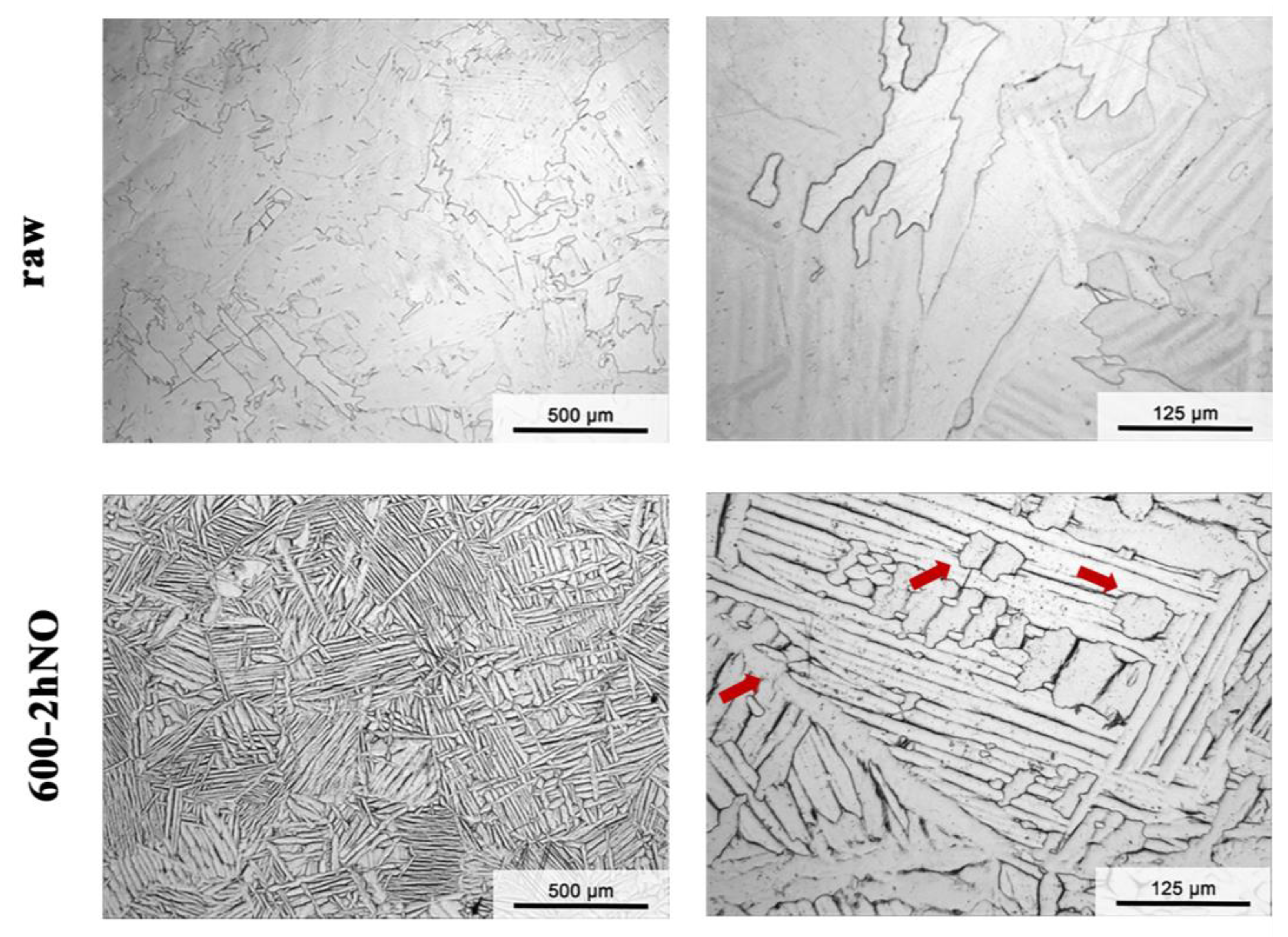
  • The local O element aggregation played a stabilizing role, and the original morphology of the α phase was partially preserved, showing a lath + equiaxed α phase structure.
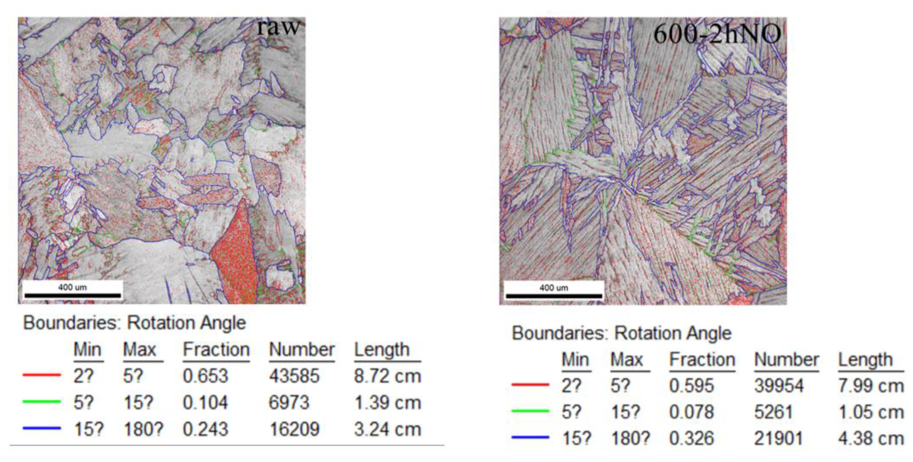
  • More large-angle grain boundaries were produced in the Ti-N-O alloy, which was due to the extrusion deformation between powders leading to the edge breaking, and the sintering temperature rise was equivalent to recrystallization.
  • Due to the low strength of cp-Ti, its application was previously limited. The Ti-N-O alloys prepared in this study have excellent mechanical properties and are prepared as bulk materials. This makes many applications possible, such as orthopedic load-bearing implants, core components of sports equipment, and so on.

Author Contributions

Conceptualization, M.S., C.Z. and G.C.; methodology, M.S., R.C. and H.H.; software, X.Z.; validation, H.H. and X.Z.; formal analysis, M.S., R.C. and Z.X.; investigation, H.H. and X.Z.; resources, C.Z. and G.C.; data curation, R.C. and Z.X.; writing—original draft preparation, M.S.; writing—review and editing, Z.X., C.Z. and G.C.; visualization, H.H. and R.C.; supervision, Z.X. and X.Z.; funding acquisition, C.Z. and G.C. All authors have read and agreed to the published version of the manuscript.

Funding

This research was supported by Sichuan Innovative Experimental Projects of Higher Education Institutions (Grant No. 2023-027). Thanks to the Southwest Jiaotong University Analysis and Testing Center and the Sinoma Analysis Center for their help in characterizing the microstructure.

Data Availability Statement

The original contributions presented in this study are included in the article. Further inquiries can be directed to the corresponding author.

Conflicts of Interest

The authors declare no conflicts of interest.

References

  1. Agrawal, R.K.; Pandey, V.; Barhanpurkar-Naik, A.; Wani, M.R.; Chattopadhyay, K.; Singh, V. Effect of Ultrasonic Shot Peening Duration on Microstructure, Corrosion Behavior and Cell Response of Cp-Ti. Ultrasonics 2020, 104, 106110. [Google Scholar] [CrossRef] [PubMed]
  2. Li, X.P.; Ji, G.; Eder, K.; Yang, L.M.; Addad, A.; Vleugels, J.; Van Humbeeck, J.; Cairney, J.M.; Kruth, J.P. Additive Manufacturing of a Novel Alpha Titanium Alloy from Commercially Pure Titanium with Minor Addition of Mo2C. Materialia 2018, 4, 227–236. [Google Scholar] [CrossRef]
  3. Maj, Ł.; Muhaffel, F.; Jarzębska, A.; Trelka, A.; Trembecka-Wójciga, K.; Kawałko, J.; Kulczyk, M.; Bieda, M.; Çimenoğlu, H. Enhancing the Tribological Performance of MAO Coatings through Hydrostatic Extrusion of Cp-Ti. J. Alloys Compd. 2025, 1010, 178246. [Google Scholar] [CrossRef]
  4. Ma, T.-H.; Chang, L.; Zhao, J.-P.; Zhou, C.-Y. Comparation of Non-Proportional Hardening Behavior and Microscopic Mechanism for CP-Ti under Strain-Controlled and Stress-Controlled Multiaxial Low Cycle Fatigue. J. Alloys Compd. 2024, 1003, 175724. [Google Scholar] [CrossRef]
  5. Atik, B.; Bozkurt, Y.B.; Kavasoğlu, Y.S.; Kovacı, H.; Çelik, A. Pitting Corrosion Performance of Plasma Oxidized Cp-Ti and Effects of Fabrication Methods. Surf. Coat. Technol. 2024, 478, 130384. [Google Scholar] [CrossRef]
  6. Zhang, L.-C.; Chen, L.-Y. A Review on Biomedical Titanium Alloys: Recent Progress and Prospect. Adv. Eng. Mater. 2019, 21, 1801215. [Google Scholar] [CrossRef]
  7. Shah, F.A.; Trobos, M.; Thomsen, P.; Palmquist, A. Commercially Pure Titanium (Cp-Ti) versus Titanium Alloy (Ti6Al4V) Materials as Bone Anchored Implants—Is One Truly Better than the Other? Mater. Sci. Eng. C 2016, 62, 960–966. [Google Scholar] [CrossRef]
  8. Senocak, T.C. Characterization and Performance of Tantalum-Tungsten Based Coatings Deposited on Cp-Ti Substrates by PVD Technique. Mater. Today Commun. 2023, 37, 107091. [Google Scholar] [CrossRef]
  9. In Vivo Assessment of Bone Enhancement in the Case of 3D-Printed Implants Functionalized with Lithium-Doped Biological-Derived Hydroxyapatite Coatings: A Preliminary Study on Rabbits. Available online: https://www.mdpi.com/2079-6412/10/10/992 (accessed on 11 May 2025).
  10. Choi, S.-W.; Jeong, J.S.; Won, J.W.; Hong, J.K.; Choi, Y.S. Grade-4 Commercially Pure Titanium with Ultrahigh Strength Achieved by Twinning-Induced Grain Refinement through Cryogenic Deformation. J. Mater. Sci. Technol. 2021, 66, 193–201. [Google Scholar] [CrossRef]
  11. Cai, Z.; Xiang, T.; Bao, W.; Chen, J.; Gao, T.; Xie, G. Enhancing Strength and Ductility of Pure Titanium by Interstitial Oxygen Atoms. Mater. Sci. Eng. A 2022, 854, 143806. [Google Scholar] [CrossRef]
  12. Aslan Çakır, M.; Yetim, T.; Bozkurt, Y.B.; Kovacı, H.; Çelik, A. Wear and Tribocorrosion Behavior of UV Curable Coated CP-Ti. Mater. Lett. 2023, 331, 133518. [Google Scholar] [CrossRef]
  13. Lütjering, G.; Williams, J.C. Commercially Pure (CP) Titanium and Alpha Alloys. In Titanium; Engineering Materials, Processes; Springer: Berlin/Heidelberg, Germany, 2007; pp. 175–201. ISBN 978-3-540-71397-5. [Google Scholar]
  14. Bosco, R.; Edreira, E.R.U.; Wolke, J.G.C.; Leeuwenburgh, S.C.G.; Van Den Beucken, J.J.J.P.; Jansen, J.A. Instructive Coatings for Biological Guidance of Bone Implants. Surf. Coat. Technol. 2013, 233, 91–98. [Google Scholar] [CrossRef]
  15. Mohammadi, M.; Akbari, A.; Warchomicka, F.; Pichon, L. Depth Profiling Characterization of the Nitride Layers on Gas Nitrided Commercially Pure Titanium. Mater. Charact. 2021, 181, 111453. [Google Scholar] [CrossRef]
  16. Körkel, A.F.K.; Jellesen, M.S.; Foss, M.; Ceccato, M.; Somers, M.A.J.; Christiansen, T.L. Thermochemical Oxidation of Commercially Pure Titanium; Controlled Formation of Robust White Titanium Oxide Layers for Biomedical Applications. Surf. Coat. Technol. 2023, 467, 129716. [Google Scholar] [CrossRef]
  17. Ye, Y.; Kure-Chu, S.-Z.; Sun, Z.; Matsubara, T.; Tang, G.; Hihara, T.; Okido, M.; Yashiro, H. Self-Lubricated Nanoporous TiO2-TiN Films Fabricated on Nanocrystalline Layer of Titanium with Enhanced Tribological Properties. Surf. Coat. Technol. 2018, 351, 162–170. [Google Scholar] [CrossRef]
  18. Yaskiv, O.I.; Pohrelyuk, I.M.; Fedirko, V.M.; Lee, D.B.; Tkachuk, O.V. Formation of Oxynitrides on Titanium Alloys by Gas Diffusion Treatment. Thin Solid Film. 2011, 519, 6508–6514. [Google Scholar] [CrossRef]
  19. Raju, K.A.K.; Biswas, A. Surface Modifications and Coatings to Improve Osseointegration and Antimicrobial Activity on Titanium Surfaces: A Statistical Review over the Last Decade. J. Orthop. 2025, 67, 68–87. [Google Scholar] [CrossRef]
  20. Fang, Y.; Liu, C.; Jin, K.; Wei, X.; Zhao, X.; Bei, H.; Zhang, Z. Additive Manufacturing of Titanium Alloys with Enhanced Strength and Uniform Ductility via Multi-Element Alloying. J. Mater. Res. Technol. 2023, 24, 6854–6860. [Google Scholar] [CrossRef]
  21. Additive Manufacturing of Ultrafine-Grained High-Strength Titanium Alloys|Nature. Available online: https://www.nature.com/articles/s41586-019-1783-1 (accessed on 27 February 2025).
  22. Wang, H.; Luo, H.L.; Chen, J.Q.; Tang, J.C.; Yao, X.Y.; Zhou, Y.H.; Yan, M. Cost-Affordable, Biomedical Ti-5Fe Alloy Developed Using Elemental Powders and Laser in-Situ Alloying Additive Manufacturing. Mater. Charact. 2021, 182, 111526. [Google Scholar] [CrossRef]
  23. Effect of Solution Treatment Temperature on Microstructure, Mechanical Properties and Corrosion Resistance of Ultra-High Nitrogen Stainless Steel|Metallurgical and Materials Transactions A. Available online: https://link.springer.com/article/10.1007/s11661-024-07568-5 (accessed on 27 February 2025).
  24. Zhang, Z.-H.; Liu, Z.-F.; Lu, J.-F.; Shen, X.-B.; Wang, F.-C.; Wang, Y.-D. The Sintering Mechanism in Spark Plasma Sintering—Proof of the Occurrence of Spark Discharge. Scr. Mater. 2014, 81, 56–59. [Google Scholar] [CrossRef]
  25. Yang, J.; Li, J.; Yan, C.; Wang, P.; Yang, H.; Qian, X.; Yang, K.; Xu, S.; Lin, J. Microstructure, Thermal Properties and Irradiation Behaviors of Uranium Nitride (UN) Nuclear Fuel Densified by Spark Plasma Sintering (SPS). J. Nucl. Mater. 2025, 608, 155709. [Google Scholar] [CrossRef]
  26. Silva, M.C.L.; Leite, M.M.B.; Raimundo, R.A.; Henriques, G.F.; Valcacer, S.M.; Mashhadikarimi, M.; Morales, M.A.; Gomes, U.U. Consolidation and Mechanical Properties of WC-Al2O3 Composite Prepared via High Energy Ball Milling and Spark Plasma Sintering. Ceram. Int. 2022, 48, 19026–19035. [Google Scholar] [CrossRef]
  27. Zabihi, M.; Emadoddin, E.; Qods, F. Enhanced Mechanical Behavior and Texture Development of Al/Al2O3 Composites Produced by Spark Plasma Sintering (SPS) and Vacuum Hot Pressing (VHP) Followed by Simple Shear Extrusion (SSE). J. Mater. Res. Technol. 2024, 33, 796–805. [Google Scholar] [CrossRef]
  28. Liu, L.; Hou, Z.; Zhang, B.; Ye, F.; Zhang, Z.; Zhou, Y. A New Heating Route of Spark Plasma Sintering and Its Effect on Alumina Ceramic Densification. Mater. Sci. Eng. A 2013, 559, 462–466. [Google Scholar] [CrossRef]
  29. Low-Temperature Nitriding of Pure Titanium by Using Hollow Cathode RF-DC Plasma—IOPscience. Available online: https://iopscience.iop.org/article/10.1088/1757-899X/202/1/012026 (accessed on 27 February 2025).
  30. Liu, J.; Wang, Z.; Ye, Z.; Jin, W.; Chen, Z.; Hu, Y.; Wu, J.; Chen, D.; Bai, B.; Wang, X.; et al. Improved Dry Sliding Wear Behavior of TA1 Titanium by Low-Temperature Plasma Nitriding by CCPN Method. Vacuum 2024, 221, 112945. [Google Scholar] [CrossRef]
  31. Kikuchi, S.; Akebono, H.; Ueno, A.; Ameyama, K. Formation of Commercially Pure Titanium with a Bimodal Nitrogen Diffusion Phase Using Plasma Nitriding and Spark Plasma Sintering. Powder Technol. 2018, 330, 349–356. [Google Scholar] [CrossRef]
  32. Dong, S.; Song, Y.; Savvakin, D.; Ivasishin, O.; Cheng, T. Impact of Hot Rolling on the Evolution of Microstructure and Mechanical Properties of Sintered Commercially Pure Ti Compacts. J. Mater. Res. Technol. 2024, 31, 133–141. [Google Scholar] [CrossRef]
  33. Zhao, P.-C.; Yuan, G.-J.; Wang, R.-Z.; Guan, B.; Jia, Y.-F.; Zhang, X.-C.; Tu, S.-T. Grain-Refining and Strengthening Mechanisms of Bulk Ultrafine Grained CP-Ti Processed by L-ECAP and MDF. J. Mater. Sci. Technol. 2021, 83, 196–207. [Google Scholar] [CrossRef]
  34. Zhang, Y.S.; Zhang, W.; Wang, X.; Lu, J.W.; Zhao, Y.H. Microstructure and Mechanical Property Evolutions of Bulk Core-Shell Structured Ti-N Alloys during Annealing. J. Alloys Compd. 2017, 710, 418–423. [Google Scholar] [CrossRef]
  35. Ye, J.; Lin, X.; Quan, L.; Yang, H.; Fu, S. Transformation of Guinier-Preston Zone in a Pre-Deformed Mg-Zn-Y-Zr Alloy. Mater. Lett. 2020, 258, 126815. [Google Scholar] [CrossRef]
Figure 1. The hardness curve of the Ti-N-O samples.
Metals 15 00554 g001
Figure 2. The compression stress–strain curve of the Ti-N-O samples.
Metals 15 00554 g002
Figure 3. The fractured surface morphology of (a) the raw sample; (b) the other Ti-N-O sample (600-2hNO, 600-3hNO, or 650-3hN-2+O).
Metals 15 00554 g003
Figure 4. The XRD patterns obtained from the 600-2hNO powder, the 600-2hNO sample, and the raw powder.
Metals 15 00554 g004
Figure 5. The SEM images of the surface of (a) the raw powder; (b) the 600-2hNO powder (the white particles in the circles are presumed to be TiO2); and (c) the 600-2hNO sample.
Metals 15 00554 g005
Figure 6. The OM images of the 600-2hNO sample and the raw sample. Red arrows point to equiaxed structures in lath structures.
Metals 15 00554 g006
Figure 7. The SEM image and EDS analysis of the 600-2hNO sample.
Metals 15 00554 g007
Figure 8. (a) The TEM image of the 600-2hNO sample; (b) the Fourier images of b; (c) the Fourier images of c; (d) the inverse Fourier images of b; and (e) the inverse Fourier images of c.
Metals 15 00554 g008
Figure 9. The grain boundary images of the raw sample and the 600-2hNO sample taken under EBSD.
Metals 15 00554 g009
Figure 10. The schematic diagram of the organization growth of the Ti-N-O alloys throughout the sintering process.
Metals 15 00554 g010
Table 1. Processing parameters of Ti-N-O alloys.
Process of Powder Nitriding/OxynitridingSample
Raw
Oxynitriding at 600 °C for 2h600-2hNO
Oxynitriding at 600 °C for 3h600-3hNO
Nitriding at 650 °C for 3 h, repeat the process twice; keep the first nitriding unchanged, and introduce air for the last 20 min of the second nitriding, i.e., oxynitriding650-3hN-2+O
Disclaimer/Publisher’s Note: The statements, opinions and data contained in all publications are solely those of the individual author(s) and contributor(s) and not of MDPI and/or the editor(s). MDPI and/or the editor(s) disclaim responsibility for any injury to people or property resulting from any ideas, methods, instructions or products referred to in the content.

