Abstract
CoCrFeNiSix (where x = 0, 0.5, 1.0, 1.5, 2.0 mol, named as H4, Si0.5, Si1.0, Si1.5, and Si2.0, respectively) high-entropy alloys (HEAs) were fabricated via hot-press sintering. The effects of Si content on the phase structure, microstructure, and mechanical properties of HEAs were investigated. The results show that the H4 alloy consists of a single FCC phase. As the Si content increases, the phases of CoCrFeNiSix HEAs transform from the FCC phase to the BCC and silicide phases. An increase in Si content can significantly enhance the hardness and yield strength of the alloys, yet at the expense of their plasticity. When the Si content increases from 0 to 2.0 mol, the hardness of the alloy increases from 280 HV to 1060 HV, the yield strength rises from 760 MPa to 1640 MPa, and the fracture strain drops to 6%. The strengthening mechanism of this HEA system mainly stems from the synergistic effect of solid solution strengthening and precipitation strengthening of silicide phases.
1. Introduction
High-entropy alloys (HEAs) represent a novel class of alloy systems. Typically, they are composed of five or more principal metallic elements, with each element’s atomic percentage ranging from 5% to 35% [1,2]. The core design concept of HEAs is to suppress the formation of intermetallic compounds by maximizing the mixing entropy (ΔSmix ≥ 1.5R), thereby facilitating the formation of simple solid solutions, such as face-centered cubic (FCC), body-centered cubic (BCC), or dual-phase structures. This unique “high-entropy effect” endows HEAs with excellent comprehensive properties, including high strength, high hardness, good wear resistance, corrosion resistance, and high-temperature stability [3,4,5,6]. For instance, the typical CoCrFeNi HEA, featuring a single FCC structure, demonstrates remarkable ductility and fracture toughness. As a result, it holds great promise in various fields, such as aerospace, nuclear industry, and high-end manufacturing [7,8]. However, the strength of the single FCC structure is relatively low, falling short of meeting performance requirements under extreme working conditions. Therefore, regulating the microstructure and mechanical properties of CoCrFeNi HEA through alloying has become a research hotspot at present.
Alloying serves as a crucial approach to regulate the microstructures and properties of HEAs. In recent years, researchers have successfully achieved multi-scale strengthening of CoCrFeNi-based alloys by adding metallic elements with large atomic radii, such as Al, Nb, V, Ti, and Mo [9,10,11,12,13]. Li et al. [14] studied AlxCoCrFeNi (x = 1, 1.5, 2, 2.5, 3) HEAs and found that the addition of Al promoted the transformation of the alloy from a single FCC structure to an FCC + BCC mixed structure. Moreover, the hardness increased gradually with the increase in Al content, reaching up to 740 HV. This was mainly attributed to the solid solution strengthening of Al atoms and the precipitation strengthening of the ordered B2 phase. He et al. [15] introduced Nb elements and formed a fine lamellar eutectic structure in CoCrFeNiNbx alloys, achieving a good combination of strength and ductility. Among them, the CoCrFeNiNb0.5 alloy exhibited outstanding comprehensive mechanical properties, with a compressive fracture strength exceeding 2300 MPa and a compressive strain of 23.6%. Hu et al. [16] showed that V had a relatively small impact on the phase structure of CoCrFeNiVx alloys. However, through solid solution strengthening and grain refinement, the hardness of the alloy increased from 240 HV to 451 HV. Kratochvíl et al. [17] found in CoCrFeNiTix alloys that the addition of Ti promoted the formation of Laves and σ phases. Through solid solution strengthening and second-phase strengthening, the hardness of the alloy reached 968 HV, and the compressive yield strength reached 2157 MPa. Shun et al. [18] studied and found that the introduction of Mo formed σ or μ phases in CoCrFeNiMox alloys. Through solid solution strengthening and second-phase strengthening, the yield stress and compressive strength of the alloy were increased from 136 MPa and 871 MPa to 929 MPa and 1441 MPa, respectively, while the fracture strain decreased from 75% to 21%.
Compared with metallic elements, non-metallic elements with small atomic radii, such as C, N, B, and Si, have been less studied in HEAs. However, their unique atomic sizes and electronic structures may trigger more complex strengthening mechanisms. Zhu et al. [19] found in AlCoCrFeNiCx alloys that the addition of C promoted the formation of ɛ phases and compositional segregation. When the carbon content was 1.0 and 1.5, the Young’s modulus of the alloy decreased significantly, but the yield stress increased. Zhang et al. [20] prepared (CoCrFeNi)100−xNx HEAs using selective laser melting and found that an increase in nitrogen content led to an increase in alloy strength but a decrease in ductility. Zhang et al. [21] studied CoCrFeNiBx eutectic HEA coatings and showed that the addition of B promoted the formation of a eutectic structure, increasing the coating hardness from 267 HV to 555 HV. Luo et al. [22] prepared CoCrFeNiSix HEAs using powder plasma arc additive manufacturing technology and found that the content of the second phase increased with the increase in Si content, resulting in a significant increase in the hardness and yield strength of the alloy, but a sharp decrease in the elongation. Cheng et al. [23] designed Al0.3CoCrFeNiSix (x = 0, 0.2, 0.5, 0.8, 1.0) HEAs and found that the addition of Si promoted the transformation from FCC to BCC/B2 phases. When x = 0.2, the yield strength and tensile strength of the alloy increased by 63% and 60%, respectively, and the elongation remained at 56%. When x = 1.0, the hardness reached 826 HV, and the wear rate decreased by two orders of magnitude. This indicates that Si can not only enhance strength through solid solution strengthening but also achieve a synergistic optimization of strength and toughness by regulating the phase structure. Although previous studies have shown that Si has a significant strengthening effect on HEAs, its strengthening mechanism in single FCC structures remains unclear. In this study, CoCrFeNiSix (x = 0, 0.5, 1.0, 1.5, and 2.0 mol) HEAs were prepared through vacuum hot-press sintering. The effects of Si content on the microstructure and mechanical properties of CoCrFeNi HEAs were investigated. The aim was to reveal the strengthening mechanism of Si elements with small atomic radii on the HEA with a single FCC structure.
2. Experimental Materials and Methods
CoCrFeNiSix (x = 0, 0.5, 1.0, 1.5, 1.0 mol, named H4, Si0.5, Si1.0, Si1.5, and Si2.0, respectively) HEAs were prepared via powder metallurgy. The specific composition design is shown in Table 1. The raw powders used in the experiment were Co, Cr, Fe, Ni, and Si powders with a purity of 99.9 wt.% and an average particle size of 75 μm. Mechanical alloying was carried out using a DECO planetary horizontal ball mill to (DECO-PBM-H-0.4L, Deke Instrument Equipment Co., Ltd., Changsha, China) prepare HEA powders. The ball-to-powder ratio of stainless-steel balls was set at 10:1. Before ball-milling, the chamber was purged with high-purity argon for 5 min to remove air interference. The ball-milling speed was set at 300 rpm. First, dry-milling was performed for 45 h to initially mix the elemental powders uniformly. Subsequently, anhydrous ethanol was added as a process control agent, and wet-milling was performed for 5 h to further refine the powders and promote uniform mixing among the elements. After wet-milling, the powders were placed in a vacuum drying oven and dried at 50 °C for 24–48 h to remove moisture and ethanol from the powders. Finally, the powders were sieved to obtain CoCrFeNiSix HEA powders with a particle size less than 75 μm.

Table 1.
Composition of CoCrFeNiSix HEA (at.%).
A vacuum hot-press furnace (ZT-25-20YVHP, Shanghai Chenhua Technology Co., Ltd., Shanghai, China) was used to sinter the alloy powders to prepare bulk CoCrFeNiSix HEA materials. Before hot-press sintering, the furnace chamber was evacuated to 5 × 10⁻² Pa to reduce the influence of impurity gases on the alloy quality. Then, heating was initiated, and oil pressure was applied. The heating rate was set at 15 °C/min, and the oil pressure index was set at 50 MPa. When the furnace temperature reached 950 °C, it was held for 2 h to allow sufficient diffusion and reaction of the alloy elements. After that, heating was stopped. When the furnace temperature dropped to 500 °C, the pressure was stopped. After the furnace temperature dropped to 100 °C, cylindrical sintered specimens with dimensions of Φ12.5 mm × 7 mm were taken out. After sintering, the carburized layer of the samples was removed through electric discharge machining, and then the samples were cut into disc specimens with a thickness of 3 mm. The disc specimens were successively rough ground and fine ground with SiC sandpapers, and then rough polished and fine polished with diamond polishing paste to meet the surface quality requirements for microstructure detection and analysis.
After the CoCrFeNiSix HEA were polished and wax-sealed, its true density (ρm) was tested using the Archimedes principle. The measurement medium was anhydrous ethanol (99.7 wt.%), and its density ρ0 was 0.79 g·cm−3. The true density of the alloy can be calculated using Formula (1).
where m0, m1, and m2 represent the mass of the sample in air before wax-sealing, the mass of the sample in air after wax-sealing, and the mass of the sample immersed in anhydrous ethanol after wax-sealing, respectively. The mass of the samples is measured using an electronic balance with a precision of 0.1 mg. The theoretical density of the bulk HEA is ρt, which can be calculated using Formula (2).
where xi is the atomic percentage of the ith component, and ρi is the density of the ith component. The relative density D of the bulk HEA sample is calculated using Formula (3).
The phase structure of bulk CoCrFeNiSix HEAs was tested using a German Bruker-D8 Advance X-ray diffractometer (XRD) (Munich, Germany). During the test, Cu-Kα radiation with a wavelength of 1.54056 Å was used. The operating tube voltage and tube current were set at 40 kV and 40 mA, respectively. The scanning angle range was 20–90° (2θ), the scanning speed was 5°/min, and the scanning step size was 0.02°. Through XRD analysis, the phase composition and phase structure changes of the alloys can be determined. The microstructures of as-sintered HEAs were observed and analyzed using a Quanta 250 cold field emission scanning electron microscope (SEM, FEI Czech Republic Limited, Brno, Czech Republic). Meanwhile, the composition of the HEAs was analyzed using an energy-dispersive X-ray spectrometer (EDAX, FEI Czech Republic Limited, Brno, Czech Republic) integrated with the SEM system to determine the distribution of each element in the alloy. The hardness of the HEAs was tested using an HVS-50 hardness tester (SFMIT, Changzhou Sanfeng Instrument Technology Co., Ltd., Changzhou, China). During the test, a load of 98 N was applied, and the holding time was 20 s. Five measurements were taken for each specimen, and the average value was taken as the measured hardness of the alloy to ensure the accuracy and reliability of the hardness data. The compression performance of HEAs was tested using an MTS810 universal testing machine (Metes Industrial Systems (China) Co., Ltd., Shanghai, China). The compression specimen had dimensions of Φ3 × 6 mm. The loading rate during the compression experiment was 2 × 10⁻⁴/s. For plastic materials, compression was carried out until 50% deformation. Four compression specimens were taken for each alloy, and four measurements were made. To reduce experimental errors, the compression mechanical properties of the alloy were determined by taking the average value of the performance indicators.
3. Results and Discussion
3.1. Density
The densities of the CoCrFeNiSix bulk HEAs after hot-press sintering are shown in Table 2. The densities of all five alloys reach over 96%, indicating that the hot-press sintering process can fabricate bulk HEAs with relatively high density. This is related to the high temperature, high pressure, and holding time. A temperature of 950 °C can provide sufficient energy for the diffusion of alloying elements, promoting the full diffusion of atoms, and thus affecting the phase structure and microstructure of the alloy. The pressure of 50 MPa helps the particles to come into close contact, which not only promotes the diffusion of elements but also affects the density of the alloy. The increase in density can significantly enhance the strength of the alloy. The 2 h holding time allows the alloying elements to diffuse and react fully, making the phase structure and properties more stable. It can also be seen from Table 2 that the density of the CoCrFeNiSix HEAs shows an upward trend with the increase of Si content. This phenomenon may be closely related to the phase evolution during the sintering process. As known from the subsequent XRD analysis results, when Si element is added to the soft CoCrFeNi HEA matrix, hard silicides are formed. During the hot-press sintering process, the hard silicides are embedded in the soft matrix, making the internal structure of the alloy more compact, thus correspondingly increasing the density of the alloy.
Table 2.
Densities of CoCrFeNiSix high-entropy alloys after hot-press sintering.
3.2. Phase Structure
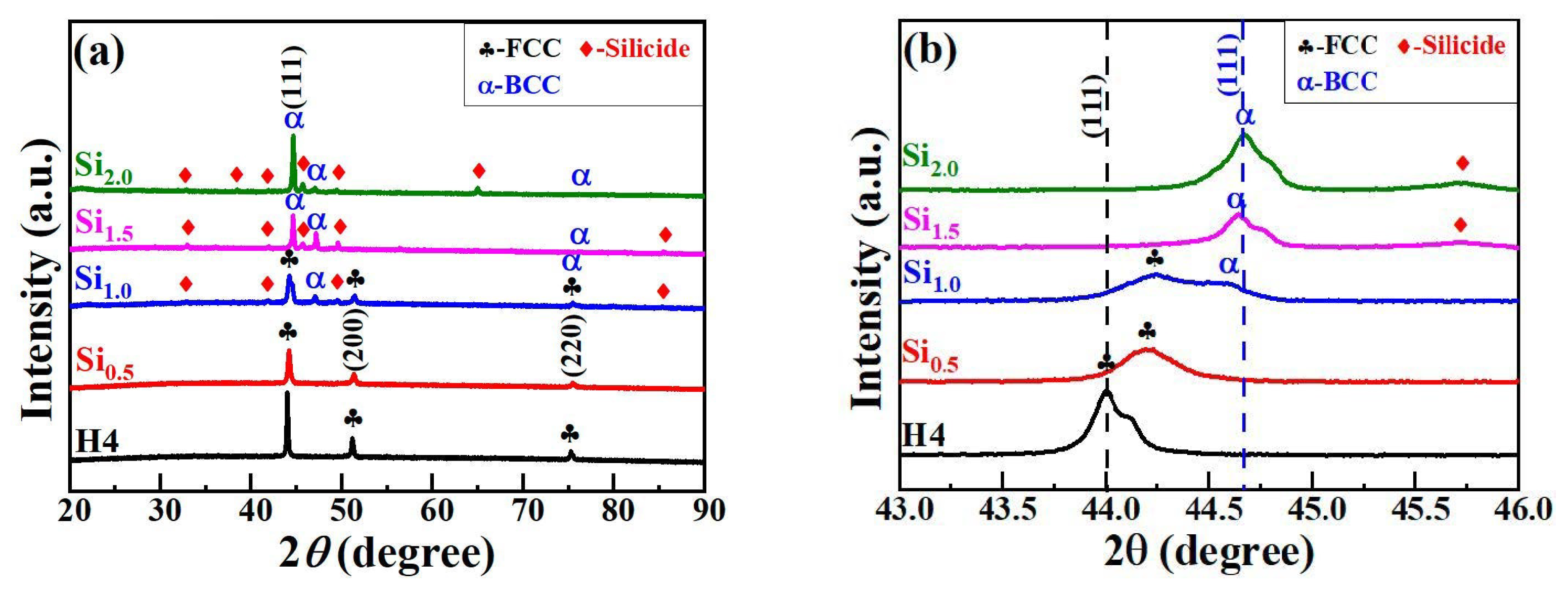
Figure 1 presents the XRD results of CoCrFeNiSix HEAs. H4 and Si0.5 alloys consist of a single FCC structure. However, as shown in Figure 1b, the FCC phase diffraction peak of the Si0.5 alloy, which is located near 44°, is significantly shifted to the right. The lattice constants of the FCC phase in H4 and Si0.5 alloys are 0.3561 nm and 0.3545 nm, respectively. Kai et al. [24] indicated that the lattice constant of H4 and Si0.5 alloys were 0.356 nm and 0.360 nm, respectively, and the lattice constant increased significantly with the increase in Si content. They believed that this was due to the entry of Si atoms into the FCC phase sublattice, leading to an increase in the lattice constant. However, in AlCoCrFeNiSix alloy, an increase in Si content resulted in a decrease in the BCC phase lattice constant from 0.2878 nm to 0.2861 nm, which is similar to the trend observed in this study [25]. This may be because of the small radius of Si atoms. When Si atoms replace larger atoms in the FCC solid solution, they cause lattice shrinkage, which leads to a decrease in the lattice constant and results in a rightward shift of the FCC diffraction peaks. When the Si content reaches 1.0 mol, a small number of BCC diffraction peaks and silicide diffraction peaks appear in the Si1.0 alloy, and the content of the FCC phase decreases accordingly. This directly leads to a decrease in the intensity of the FCC phase diffraction peak, while the intensity of the BCC phase diffraction peak begins to increase. When the Si content further increases to 1.5 mol and 2.0 mol, the FCC phase in the Si1.5 and Si2.0 alloys gradually disappears, and the BCC phase becomes one of the main phases as its content increases continuously. Therefore, the intensity of the BCC diffraction peak continues to increase. The XRD results of CoCrFeNiSix HEAs fully indicate that the Si element promotes the phase transition from the FCC phase to the BCC phase and silicide phase.
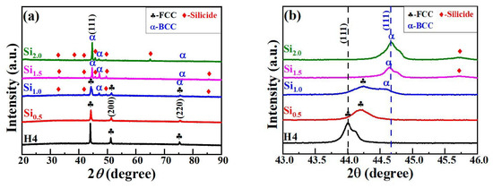
Figure 1.
XRD results of CoCrFeNiSix HEAs: (a) 20°–90°; (b) 43°–46°.
Zhang [26], Yang [27], and Guo [28] proposed the H-S-δ criterion, the Ω-δ criterion, and the VEC criterion, respectively, based on existing research on the phase structures of HEAs. The H-S-δ criterion indicates that when the ΔHmix, ΔSmix, and δ of an alloy satisfy the following conditions: −20 < ΔHmix < 5 KJmol−1, 12 < ΔSmix < 17.5 JK−1mol−1, and δ < 6.4%, the alloy has a tendency to form a simple solid solution phase. Yang et al. [27] put forward a new criterion for solid solution formation by integrating the theoretical melting point (Tm), ΔHmix, ΔSmix, and δ of HEAs: Ω ≥ 1.1 and δ ≤ 6.6%. Guo et al. [28] proposed the VEC criterion, which can better predict the type of solid solution phase: (a) when VEC < 6.87, a single BCC structure solid solution phase is formed; (b) when VEC ≥ 8, a single FCC structure solid solution phase is formed; (c) when 6.87 ≤ VEC < 8, the alloy is composed of FCC+BCC phases. The formulas for calculating ΔHmix, ΔSmix, δ, Ω, and VEC are presented below.
where represents the binary mixing enthalpy of the ith and jth components. The binary mixing enthalpies among the elements in the CoCrFeNiSix HEAs are presented in Table 3. ci and cj are the atomic percentage contents of the ith and jth components, respectively. R = 8.314 J/(mol·K), n is the number of components, and ri is the atomic radius of the ith component. (Tm)i is the melting point of the ith component; and (VEC)i is the valence electron concentration of the ith component. The thermodynamic parameters and VEC values of the CoCrFeNiSix HEAs, calculated according to Formulas (4)–(8), are listed in Table 4.
Table 3.
Binary mixing enthalpies among the elements in the CoCrFeNiSix HEAs. Adapted from Ref. [29].
Table 4.
Thermodynamic parameters, δ and VEC values of the CoCrFeNiSix HEAs.
According to the H-S-δ criterion, only the Si0.5 alloy meets this condition and has a tendency to form a simple solid solution phase, while the other alloys tend to form intermetallic compound phases. In fact, both the H4 and Si0.5 alloys are of the FCC solid solution phase, and the other alloys have structures of FCC+BCC+silicide phases or BCC + silicide phases. Evidently, this criterion is not applicable to the phase prediction of CoCrFeNiSix HEAs. According to the Ω-δ criterion, both the H4 and Si0.5 alloys are of the FCC solid solution phase, and the other alloys tend to form compound phases. The prediction results of this criterion are in good agreement with the XRD analysis results. According to the VEC criterion, the VEC value of the Si2.0 alloy is less than 6.87, and it should form a single BCC phase. However, this alloy consists of BCC+silicide phases. The Si0.5, Si1.0, and Si1.5 alloys should form FCC + BCC phases, but the actual results do not match the predictions. The VEC value of the H4 alloy is greater than 8, and it should form a single FCC phase, which is basically consistent with the XRD results. This indicates that the above-mentioned solid solution phase formation criteria cannot accurately predict the phase structure of CoCrFeNiSix HEAs and need to be further improved.
In addition, the phase structure of CoCrFeNiSix HEAs is also closely related to its preparation process. Kai et al. [24] prepared CoCrFeNiSix (x = 0.25, 0.5, 1.0) HEAs via the arc melting process and found that two alloys with low Si content consisted of a single FCC phase, while the CoCrFeNiSi alloy was composed of FCC+BCC phases. Huang et al. [30] prepared CoCrFeNiSix (x = 0, 0.5, 1.0) HEAs using the arc melting process and discovered that the CoCrFeNi alloy was a single FCC phase, the Si0.5 alloy was composed of FCC + BCC phases, and the Si1.0 alloy was composed of FCC + BCC + NixSiy phases. Hao et al. [31] prepared CoCrFeNiSix (x = 0, 0.5, 1.0, 1.5, 2.0) HEA coatings through the laser cladding process and found that the CoCrFeNi alloy was a single FCC phase, and the Si0.5 alloy was composed of FCC + BCC1 + BCC2 phases. When the Si content increased to 2.0, the Si2.0 alloy coating completely transformed into BCC1 + BCC2 phases. However, in this study, the CoCrFeNiSix alloys prepared using the powder metallurgy process exhibited a phase structure of the FCC phase at low Si content (x = 0 and 0.5). When x = 1.0, the BCC phase and silicide phase began to form. With the further increase in Si content, the FCC phase transformed into the BCC phase and silicide phase. These results may be attributed to two factors. Firstly, low Si content facilitates the improvement of lattice vacancies during alloy crystallization and reduces lattice distortion, and thus the phase structure does not change significantly. When the Si content is high, the excess Si atoms exist in the form of substitutional solid solutions. This increases the distortion energy of the alloy while reducing the free energy, which promotes the formation of the BCC phase. On the other hand, the high temperature, high pressure, and long-term heat preservation conditions during hot-press sintering are conducive to the full diffusion of alloying elements. Moreover, the binary mixing enthalpies of Si with other alloying elements are more negative. For example, the binary mixing enthalpies of Si-Ni, Si-Co, and Si-Cr are −40 kJ/mol, −38 kJ/mol, and −37 kJ/mol, respectively. This provides favorable conditions for the formation of silicide phases.
3.3. Microstructure
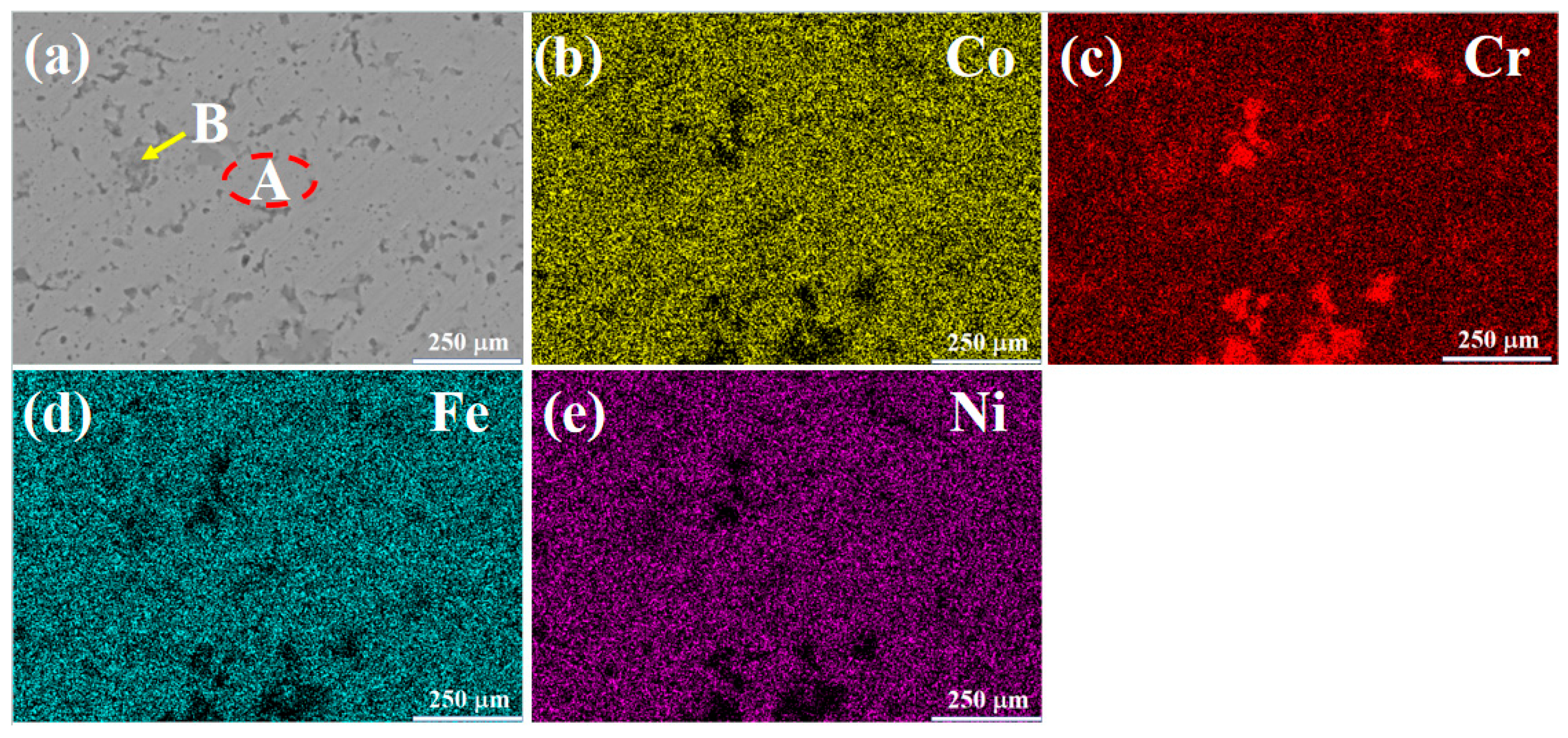
Figure 2 presents the SEM morphology and mapping results of the CoCrFeNi (H4) alloy. The microstructure is composed of a light-colored matrix phase (Region A) and a dark gray intergranular phase (Region B). From the mapping results, the matrix phase mainly contains Co, Fe, and Ni elements, while the dark gray phase is mainly composed of Cr elements. By combining with the XRD results, it can be inferred that the matrix is an FCC solid solution phase, and the dark gray phase is a Cr-rich FCC solid solution phase. These two FCC phases have the same crystal structure but different lattice constants. Consequently, a slight peak shift can be observed in Figure 1b. Table 5 shows the EDS results of the light-colored Region A and the dark gray Region B in the microstructure of the H4 alloy. Region A of this alloy has higher contents of Co, Fe, and Ni, while Region B has a higher Cr content.
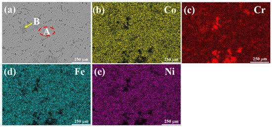
Figure 2.
SEM images and mapping results of H4 alloy: (a) SEMimage; (b) Co; (c) Cr; (d) Fe; (e) Ni.
Table 5.
EDS results of H4 alloy (at.%).
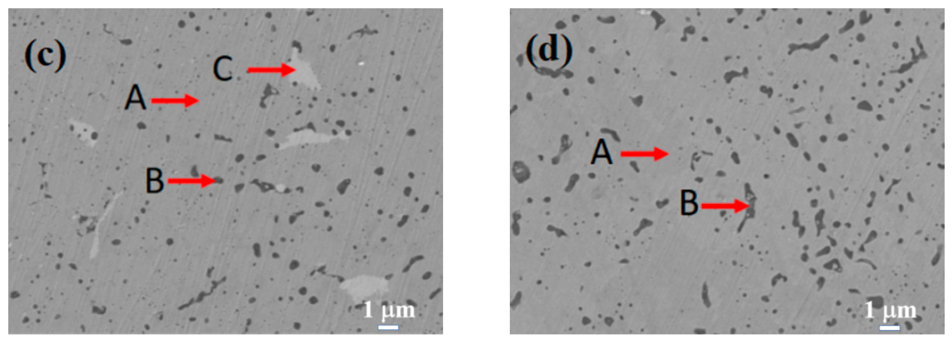
Figure 3 displays the SEM images of the Si0.5, Si1.0, Si1.5, and Si2.0 alloys. Table 6 presents the EDS results of these four alloys. As depicted in Figure 3a, in the matrix structure (Region A) of the Si0.5 alloy, some pit-shaped structures and a small number of dark gray regions (Region B) are distributed. These pit-shaped structures might be grain boundaries or defects exposed after being corroded by aqua regia. Based on the EDS and XRD results, it can be deduced that the light gray matrix Region A is an FCC solid solution phase. The EDS results of the dark gray Region B indicate that it is a Cr-rich phase. Its content is relatively low, so it is not shown in the XRD pattern. In the matrix of the Si1.0 alloy (Region A), there are more intergranular structures (Region C) and a small number of black structures (Region B). From the EDS results, the contents of alloying elements in the matrix phase are relatively uniform. Region B has higher contents of Si and Ni, and Region C has higher contents of Cr, Fe, and Si. By integrating with the XRD results, it can be inferred that Region A remains an FCC solid solution phase, Region B is a silicide phase, and Region C is a BCC phase. Unlike the H4, Si0.5, and Si1.0 alloys, the matrices (Region A) of both the Si1.5 and Si2.0 alloys have more black-dot-shaped structures (Region B). The matrix of the Si1.5 alloy also contains a small number of gray-white structures (Region C). By combining the XRD and EDS results, it is inferred that Region A is a BCC phase region, Region B is a silicide phase region, and Region C is a Cr-rich phase.
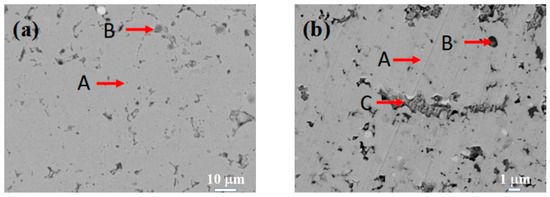
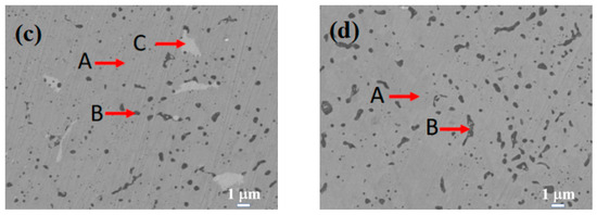
Figure 3.
SEM images of CoCrFeNiSix HEAs: (a) Si0.5; (b) Si1.0; (c) Si1.5; (d) Si2.0.
Table 6.
EDS results of the CoCrFeNiSix alloys (at.%).
3.4. Mechanical Properties
3.4.1. Hardness
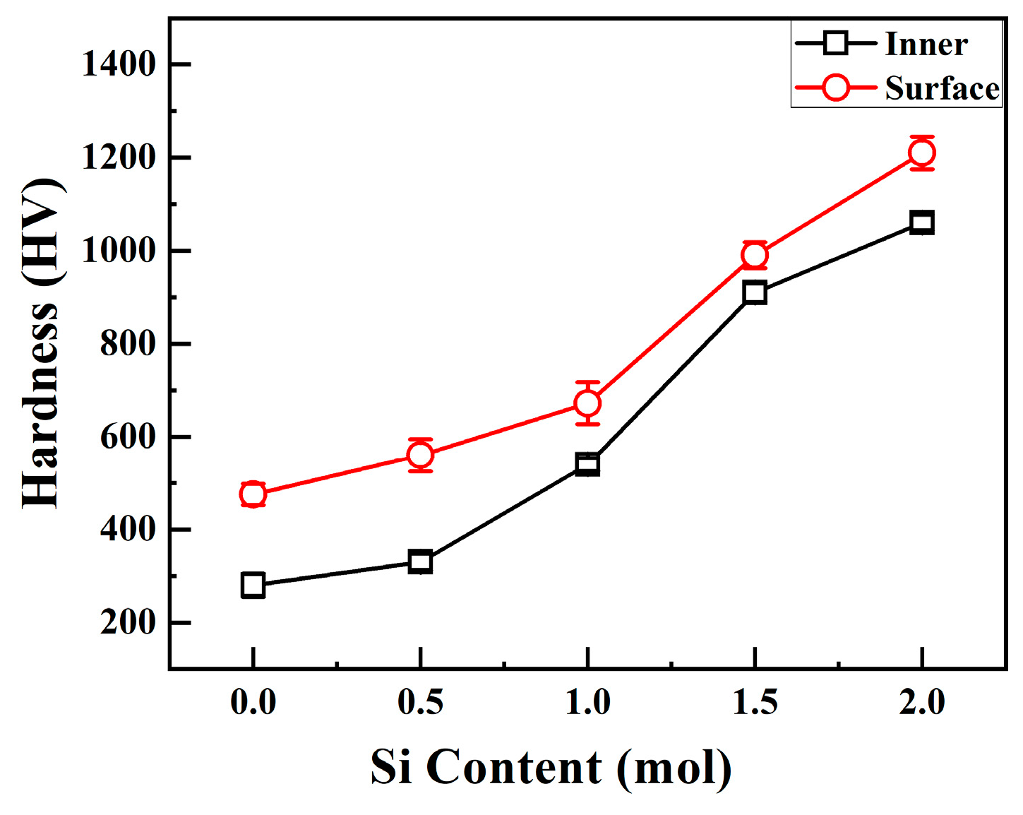
Figure 4 shows the relationship between the interior and surface hardness of CoCrFeNiSix HEAs and the Si content. When x = 0, the interior and surface hardness values of the H4 alloy are 280 HV and 386 HV, respectively. When x = 0.5 mol, the surface and interior hardness values of the Si0.5 alloy increase to 330 HV and 560 HV, respectively. As the Si content continues to increase, the hardness of the alloy keeps rising. When the Si content increases to 2.0 mol, the surface and interior microhardness values of the Si2.0 alloy increase to 1060 HV and 1210 HV, respectively. Both the surface and interior hardness of CoCrFeNiSix HEAs increase with the increase in Si content.
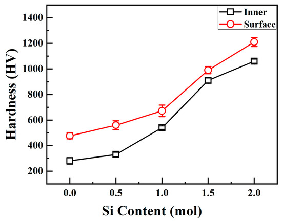
Figure 4.
Surface and internal hardness of CoCrFeNiSix HEAs.
It can also be observed from Figure 4 that the surface hardness of CoCrFeNiSix HEAs is higher than the interior hardness. This phenomenon is similar to the increase in the hardness of cemented carbide caused by the diffusion carburization during the preparation of cemented carbide. During the hot-press sintering process of HEAs, the graphite mold comes into contact with the alloy powder. Under high-temperature conditions, the carbon atoms inside the graphite mold diffuse and combine with the alloy powder, forming a hard carburized layer on the surface of the alloy. In the carburized layer, both carbon atoms and silicon atoms have small atomic radii and are easily dissolved in the lattice sites. Alternatively, carbon atoms form hard metal carbides and silicides with other alloying elements. Consequently, solid solution strengthening and precipitation strengthening effects are exerted on the surface, resulting in a significant increase in the surface hardness of the alloy.
Huang et al. [30] prepared the CoCrFeNi alloy using the vacuum arc melting process, and its hardness was approximately 90 HV. The hardness values of the Si0.5 and Si1.0 alloys were approximately 150 HV and 654 HV, respectively. Hao et al. [31] prepared the H4 alloy using the laser cladding process, and its hardness was approximately 452 HV. The hardness values of the Si0.5 and Si1.0 alloys were approximately 483 HV and 550 HV, respectively. The hardness values of the H4, Si0.5, and Si1.0 alloys prepared using the vacuum hot-press sintering process in this study are 280 HV, 330 HV, and 540 HV, respectively. It can be seen that for the same alloy, the hardness varies significantly when prepared using different processes, which may be related to the alloy phase structure and micro defects. In addition, Mohammadpour et al. [32] found that the hardness of the CrSiN thin film formed after doping Si into CrN increased from 29 GPa to 36 GPa. In this study, when the Si content increased from 0 to 2.0 mol, the hardness of the CoCrFeNiSix alloy significantly increased from 280 HV to 1060 HV. By comparison, the increase in the hardness of the alloy in this study is more remarkable. This may be due to the differences in the research systems. Reference [32] focuses on thin-film coatings, while this study is aimed at bulk high-entropy alloys. Moreover, the differences in alloy composition and preparation processes can also affect the effect of hardness enhancement.
3.4.2. Room-Temperature Compression Property
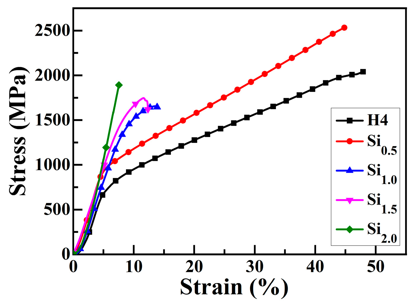
Figure 5 presents the engineering stress–strain curve of CoCrFeNiSix HEAs under compression at room temperature. The mechanical performance parameters of CoCrFeNiSix HEAs obtained from Figure 5 are listed in Table 7. The compressive yield (σ0.2) of H4 and Si0.5 alloys are 760 MPa and 910 MPa, respectively. After being compressed to 50% deformation, no fracture failure occurs, indicating that these alloys have relatively low strength but high plasticity. When the Si content increases above 1.0 mol, the strength of the HEA is enhanced, yet its plasticity is significantly reduced. The yield strength, fracture strength, and fracture strain of the Si1.0 alloy are 1570 MPa, 1630 MPa, and 17%, respectively, exhibiting a good combination of high strength and ductility. When the Si content increases to 1.5 mol, the fracture strain of the alloy decreases to 4%, while its compressive yield strength and compressive fracture strength increase to 1640 MPa and 1710 MPa, respectively. When the Si content is further increased to 2.0 mol, the fracture strength of the alloy increases to 1880 MPa, the compressive fracture strain decreases to 6%, and no significant plastic deformation is observed, displaying significant brittle characteristics. In comparison, the Si1.0 alloy not only has high strength but also possesses certain plasticity, which makes it promising to be used as a structural material in modern industry.
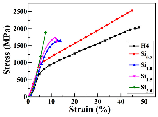
Figure 5.
Engineering stress–strain curve of CoCrFeNiSix HEAs under compression at room temperature.
Table 7.
Room-temperature compression properties of CoCrFeNiSix HEAs.
3.4.3. Strengthening Mechanism of Mechanical Property
The mechanical properties of CoCrFeNiSix HEAs are closely associated with their phase evolution law. Compared with the BCC phase, HCP phase, and intermetallic compound phase, the FCC solid solution generally has lower strength and higher plasticity. Therefore, the H4 and Si0.5 alloys, which possess a single FCC solid solution phase, exhibit low hardness, low compressive yield strength, and high compressive fracture strain. When the Si content increases to 1.0 mol, due to the large difference between its atomic radius and those of the four elements Co, Cr, Fe, and Ni in the same second period, the substitutional solid solution formed is not as stable as before, resulting in severe lattice distortion. Simultaneously, Si tends to cluster around dislocations, forming Cottrell atmospheres that impede dislocation slip, thus generating a strong solid solution strengthening effect. This leads to a significant increase in alloy strength and a notable decrease in alloy plasticity. Additionally, the formation of the BCC phase and silicide phase, which have higher strength and lower plasticity, further enhances the alloy’s strength, causing a substantial increase in the strength of the Si1.0 alloy. When the Si content increases to 1.5 mol, the FCC phase in the Si1.5 alloy is completely transformed into the BCC phase and silicide phase. As a result, the compressive yield strength and fracture strength of the alloy are further enhanced, while the compressive fracture strain is further reduced. However, when the Si content increases to 2.0 mol, although the alloy phase structure remains a single silicide phase, the increase in silicide content causes a sharp increase in grain size. This leads to an increase in alloy brittleness and a drastic decrease in plasticity, yet the improvement in compressive fracture strength is not significant.
Zhang et al. [33] studied the phase evolution and mechanical properties of CrFeNiSix (x = 0.05, 0.15, 0.25) alloys and found that the addition of Si led to the formation of (Cr, Si)-rich σ phases. These effectively hindered the migration of dislocations and grain boundaries, resulting in grain refinement. Meanwhile, the presence of the σ phase suppressed the formation of twinning. Compared with the CrFeNi alloy, the strength and hardness of the CrFeNiSix alloy were significantly improved, but the plasticity was slightly reduced. Xu et al. [34] studied the microstructure and mechanical properties of (VNbTiTa)100−xSix (x = 0, 2.5, 5, 10) refractory HEAs and found that the equimolar VNbTiTa alloy had a room temperature yield strength of 704 MPa and good compressive ductility (fracture strain > 50%). After adding the Si element, a BCC + M5Si3 eutectic formed in the interdendritic region. When the Si content reached 10%, a larger block-shaped M3Si phase formed, resulting in a yield strength of 1671 MPa for the HEA. The phase structure of the CoCrFeNiSix HEAs prepared using the powder metallurgy method in this study transforms from a single FCC phase to an FCC + silicide phase, then to an FCC + BCC + silicide phase, and finally to a BCC + silicide phase. Meanwhile, the hardness of the alloy increases from 280 HV to 1060 HV, and the compressive fracture strength also increases to 1880 MPa. Evidently, the high strength of the CoCrFeNiSix alloys is the result of the combined action of solid solution strengthening, precipitation strengthening, and strengthening due to phase structure transformation.
4. Conclusions
(1) The CoCrFeNiSix HEAs prepared using hot-press sintering exhibit good density performance. The relative density of all alloys exceeds 96% and shows an upward trend with increasing Si content.
(2) The phase composition varies with the Si content: The H4 and Si0.5 alloys show a single FCC structure. The Si1.0 alloy is composed of an FCC phase, a minor BCC phase, and a minor silicide phase. The Si1.5 and Si2.0 alloys consist of a BCC phase and a silicide phase. Silicon plays a key role as a modifier. It promotes the transformation from the FCC phase to a combination of the BCC and silicide phases. This is achieved by increasing the lattice distortion energy and facilitating the formation of silicides. The negative binary mixing enthalpies of Si with Co, Cr, and Ni contribute to this process.
(3) Increasing the Si content remarkably enhances the hardness and yield strength while reducing plasticity. When the Si content increases from 0 to 2.0 mol, the hardness increases from 280 HV to 1060 HV, the yield strength rises from 760 MPa to 1640 MPa, and the fracture strain drops to 6%. The main strengthening mechanisms are the synergistic effects of solid solution strengthening, which is caused by Si atoms inducing lattice distortion, and precipitation strengthening, resulting from the formation of hard silicide phases.
Author Contributions
Methodology, B.R. and Y.Z.; Investigation, B.R., R.Z., and A.J.; Resources, A.J. and J.L.; Data curation, J.L. and Z.L.; Writing—original draft preparation, B.R. and J.L.; Writing—review and editing, A.J., R.Z. and Z.L.; Project administration, B.R., J.L. and Y.Z.; Funding acquisition, R.Z., J.L. and B.R. All authors have read and agreed to the published version of the manuscript.
Funding
This research was funded by the key scientific research project plan of colleges and universities in Henan Province, Grant No. 22A430014, HENAN PROVINCE SCIENCE AND TECHNOLOGY RESEARCH PLAN PROJECT, Grant No. 232102231007, YOUNG BACKBONE TEACHER TRAINING PROGRAM OF HENAN PROVINCIAL COLLEGES AND UNIVERSITIES, Grant No. 2020GGJS271, ZHENGZHOU BASIC RESEARCH AND APPLIED BASIC RESEARCH SPECIAL FUND PROJECT, Grant No. ZZSZX202105.
Data Availability Statement
The original contributions presented in this study are included in the article. Further inquiries can be directed to the corresponding authors.
Conflicts of Interest
The authors declare no conflicts of interest.
References
- Yeh, J.W.; Chen, S.K.; Lin, S.J.; Gan, J.Y.; Chin, T.S.; Shun, T.T.; Tsai, C.H.; Chan, S.Y. Nanostructured high-entropy alloys with multiple principal elements: Novel alloy design concepts and outcomes. Adv. Eng. Mater. 2004, 6, 299–303. [Google Scholar] [CrossRef]
- Cantor, B. Multicomponent and high entropy alloys. Entropy 2014, 16, 4749–4768. [Google Scholar] [CrossRef]
- Yang, Y.-F.; Hu, F.; Xia, T.; Li, R.-H.; Bai, J.-Y.; Zhu, J.-Q.; Xu, J.-Y.; Zhang, G.-F. High entropy alloys: A review of preparation techniques, properties and industry applications. J. Alloys Compd. 2025, 1010, 177691. [Google Scholar] [CrossRef]
- Liu, J.; Lv, Z.; Wu, Z.; Zhang, J.; Zheng, C.; Chen, C.; Ju, D.; Che, L. Research progress on the influence of alloying elements on the corrosion resistance of high-entropy alloys. J. Alloys Compd. 2024, 1002, 175394. [Google Scholar] [CrossRef]
- Laurent-Brocq, M.; Denax, L.; Joubert, J.-M.; Esin, V.A.; Duchateau, T.; Mereib, D.; Monnier, J.; Perrière, L.; Pires Brazuna, R.; Villeroy, B. High-temperature stability of chemically architectured high entropy alloys studied by X-ray diffraction and diffusion modelling. J. Alloys Compd. 2024, 998, 175003. [Google Scholar] [CrossRef]
- Wang, X.; Wang, B.; Yu, Y.; Liu, S.; Tian, H.; Jiang, L.; Chen, F.; Gao, H. Combining spark plasma sintering with laser cladding: A new strategy for fabricating microstructure of defect-free and highly wear-resistant AlCoCrFeNi high-entropy alloy. J. Mater. Res. Technol. 2024, 32, 2101–2114. [Google Scholar] [CrossRef]
- Zhang, F.; Chen, X.; Liu, H.; Che, L.; Pan, L.; Zhou, T.; Guo, C. Recent developments in CoCrFeNi-based high entropy alloy coatings: Design, synthesis, and properties. J. Alloys Compd. 2025, 1018, 179193. [Google Scholar] [CrossRef]
- Miao, X.; Liu, G.; Sun, L.; Liu, Z.; Xu, C.; Han, Z.; Zhang, G. Serrated flow stress in the CoCrFeNi multi-principal element alloys with different grain sizes and added Re. Intermetallics 2024, 172, 108385. [Google Scholar] [CrossRef]
- Zhang, F.; He, J.; Wu, Y.; Mao, H.; Wang, H.; Liu, X.; Jiang, S.; Nieh, T.G.; Lu, Z. Effects of Ni and Al on precipitation behavior and mechanical properties of precipitation-hardened CoCrFeNi high-entropy alloys. Mater. Sci. Eng. A 2022, 839, 142879. [Google Scholar] [CrossRef]
- Liu, W.H.; He, J.Y.; Huang, H.L.; Wang, H.; Lu, Z.P.; Liu, C.T. Effects of Nb additions on the microstructure and mechanical property of CoCrFeNi high-entropy alloys. Intermetallics 2015, 60, 1–8. [Google Scholar] [CrossRef]
- Fan, R.; Wang, L.; Zhao, L.; Wang, L.; Zhao, S.; Zhang, Y.; Cui, B. Synergistic effect of Nb and Mo alloying on the microstructure and mechanical properties of CoCrFeNi high entropy alloy. Mater. Sci. Eng. A 2022, 829, 142153. [Google Scholar] [CrossRef]
- Zeng, Y.; Guo, Y.; Yang, Q.; Li, Z.; Wang, Y.; Wang, G.; Guo, Z.; Chen, Z. Effect of Ti, Mn and Mo on the microstructure and properties of CoCrFeNi high entropy alloy coatings prepared by laser cladding. Mater. Today Commun. 2024, 41, 110509. [Google Scholar] [CrossRef]
- Wang, W.L.; Kong, Z.H. Phase separation and microhardness of rapidly solidified high-entropy CoCrFeNiCux alloys. J. Alloys Compd. 2021, 853, 156451. [Google Scholar] [CrossRef]
- Li, D.Y.; Zhang, Y. The ultrahigh charpy impact toughness of forged AlxCoCrFeNi high entropy alloys at room and cryogenic temperatures. Intermetallics 2016, 70, 24–28. [Google Scholar] [CrossRef]
- He, F.; Wang, Z.; Cheng, P.; Wang, Q.; Li, J.; Dang, Y.; Wang, J.; Liu, C.T. Designing eutectic high entropy alloys of CoCrFeNiNbx. J. Alloys Compd. 2016, 656, 284–289. [Google Scholar] [CrossRef]
- Hu, M.; Jiang, X.; Dong, M.; Hu, M.; Yang, Y. Preparation and effect of vanadium addition on the mechanical properties of CoCrFeNiVx high-entropy alloy. J. Mater. Res. Technol. 2023, 27, 7705–7712. [Google Scholar] [CrossRef]
- Kratochvíl, P.; Thürlová, H.; Nováček, V.; Strakošová, A.; Čech, J.; Karlík, M.; Haušild, P.; Čapek, J.; Průša, F. Understanding the influence of Ti content on mechanically alloyed and sintered CoCrFeNiTix high entropy alloy. J. Mater. Res. Technol. 2025, 35, 7371–7383. [Google Scholar] [CrossRef]
- Shun, T.-T.; Chang, L.-Y.; Shiu, M.-H. Microstructure and mechanical properties of multiprincipal component CoCrFeNiMox alloys. Mater. Charact. 2012, 70, 63–67. [Google Scholar] [CrossRef]
- Zhu, J.M.; Fu, H.M.; Zhang, H.F.; Wang, A.M.; Li, H.; Hu, Z.Q. Microstructure and compressive properties of multiprincipal component AlCoCrFeNiCx alloys. J. Alloys Compd. 2011, 509, 3476–3480. [Google Scholar] [CrossRef]
- Zhang, Y.; Ye, S.; Ke, H.; Chan, K.C.; Wang, W. In situ synthesis of N-containing CoCrFeNi high entropy alloys with enhanced properties fabricated by selective laser melting. Mater. Des. 2023, 229, 111891. [Google Scholar] [CrossRef]
- Zhang, Q.; Si, Y.; Han, B.; Li, M.; Wang, Q.; Bian, W.; Xue, X. Solidification evolution and corrosion performance of CoCrFeNiBx eutectic high entropy alloy coatings. Surf. Coat. Technol. 2024, 483, 130760. [Google Scholar] [CrossRef]
- Luo, J.L.; Wang, J.K.; Su, C.C.; Geng, Y.F.; Chen, X.Z. Microstructure and mechanical properties of CoCrFeNiSix (x=0, 0.25, 0.5, 0.75) high-entropy alloys based on powder plasma arc additive manufacturing. J. Mater. Eng. Perform. 2024, 33, 12413–12423. [Google Scholar] [CrossRef]
- Cheng, P.; Zhao, Y.; Xu, X.; Wang, S.; Sun, Y.; Hou, H. Microstructural evolution and mechanical properties of Al0.3CoCrFeNiSix high-entropy alloys containing coherent nanometer-scaled precipitates. Mater. Sci. Eng. A 2020, 772, 138681. [Google Scholar] [CrossRef]
- Kai, W.; Cheng, F.P.; Liao, C.Y.; Li, C.C.; Huang, R.T.; Kai, J.J. The oxidation behavior of the quinary FeCoNiCrSix high-entropy alloys. Mater. Chem. Phys. 2018, 210, 362–369. [Google Scholar] [CrossRef]
- Liu, H.; Sun, S.; Zhang, T. Effect of Si addition on microstructure and wear behavior of AlCoCrFeNi high-entropy alloy coatings prepared by laser cladding. Surf. Coat. Technol. 2021, 405, 126522. [Google Scholar] [CrossRef]
- Zhang, Y.; Zhou, Y.J. Solid solution formation criteria for high entropy alloys. Mater. Sci. Forum 2007, 561–565, 1337–1339. [Google Scholar]
- Yang, X.; Zhang, Y. Prediction of high-entropy stabilized solid-solution in multi-component alloys. Mater. Chem. Phys. 2012, 132, 233–238. [Google Scholar] [CrossRef]
- Guo, S.; Liu, C.T. Phase stability in high entropy alloys: Formation of solid-solution phase or amorphous phase. Prog. Nat. Sci. Mater. Int. 2011, 21, 433–446. [Google Scholar] [CrossRef]
- Takeuchi, A.; Inoue, A. Classification of bulk metallic glasses by atomic size difference, heat of mixing and period of constituent elements and its application to characterization of the main alloying element. Mater. Trans. 2005, 46, 2817–2829. [Google Scholar] [CrossRef]
- Huang, L.; Wang, X.J.; Jia, F.C.; Zhao, X.C.; Huang, B.X.; Ma, J.; Wang, C.Z. Effect of Si element on phase transformation and mechanical properties for FeCoCrNiSix high entropy alloys. Mater. Lett. 2021, 282, 128809. [Google Scholar] [CrossRef]
- Hao, W.J.; Sun, R.L.; Niu, W.; Li, X.L.; Gu, M.; Zuo, R.Y. Study on microstructure and corrosion resistance of CoCrFeNiSix high-entropy alloy coating by laser cladding. Surf. Technol. 2021, 50, 343–348. (In Chinese) [Google Scholar]
- Mohammadpour, E.; Liew, W.Y.H.; Radevski, N.; Lee, S.; Mondinos, N.; Altarawneh, M.; Minakshi, M.; Amri, A.; Rowles, M.R.; Lim, H.N.; et al. High temperature (up to 1200 °C) thermal-mechanical stability of Si and Ni doped CrN framework coatings. J. Mater. Res. Technol. 2021, 14, 2406–2419. [Google Scholar] [CrossRef]
- Zhang, H.; Chen, K.; Wang, Z.; Zhou, H.; Gao, K.; Du, Y.; Su, Y. Microstructure and mechanical properties of novel Si-added CrFeNi medium-entropy alloy prepared via vacuum arc-melting. J. Alloys Compd. 2022, 904, 164136. [Google Scholar] [CrossRef]
- Xu, Z.Q.; Ma, Z.L.; Tan, Y.; Wang, M.; Zhao, Y.; Cheng, X.W. Effects of Si additions on microstructures and mechanical properties of VNbTiTaSix refractory high-entropy alloys. J. Alloys Compd. 2022, 900, 163517. [Google Scholar] [CrossRef]

Disclaimer/Publisher’s Note: The statements, opinions and data contained in all publications are solely those of the individual author(s) and contributor(s) and not of MDPI and/or the editor(s). MDPI and/or the editor(s) disclaim responsibility for any injury to people or property resulting from any ideas, methods, instructions or products referred to in the content. |
© 2025 by the authors. Licensee MDPI, Basel, Switzerland. This article is an open access article distributed under the terms and conditions of the Creative Commons Attribution (CC BY) license (https://creativecommons.org/licenses/by/4.0/).