Article

Lightweight Ti3VNbAl0.5Zrx (x = 0, 0.1, 0.5, and 1) Refractory High-Entropy Alloys with an Optimized Balance of Strength and Ductility

1
College of Material Science and Engineering, Taiyuan University of Technology, Taiyuan 030024, China
2
Key Laboratory of Interface Science and Engineering in Advanced Materials, Ministry of Education, Taiyuan of Technology, Taiyuan 030024, China
*
Authors to whom correspondence should be addressed.
Metals 2025, 15(5), 503; https://doi.org/10.3390/met15050503
Submission received: 20 March 2025 / Revised: 28 April 2025 / Accepted: 29 April 2025 / Published: 30 April 2025
(This article belongs to the Special Issue Feature Papers in Entropic Alloys and Meta-Metals)

Abstract

:
Achieving a balance between strength and room-temperature ductility remains an urgent need and a significant challenge for body-centered cubic (BCC) structure materials. In this paper, a good combination of strength and ductility in single-phase BCC-structured Ti3VNbAl0.5Zrx (x = 0, 0.1, 0.5, and 1) lightweight high-entropy alloys (LHEAs) was designed by reducing the valence-electron concentration in combination with the d-electron theory. The influences of Zr on the microstructures and mechanical properties of the alloys were systematically studied. The yield strengths of Zr0, Zr0.1, Zr0.5, and Zr1 alloys were 644 MPa, 703 MPa, 827 MPa, and 904 Mpa, respectively. The tensile strains of Zr0, Zr0.1, Zr0.5, and Zr1 alloys were 29%, 30%, 20%, and 16%, respectively. The deformation mechanism was studied using transmission electron microscopy (TEM). The results demonstrate that the alloys could still maintain single-phase BCC structure after deformation, and neither phase transformation nor twinning was detected during the deformation process. The main deformation mechanism of the Zr1 alloy is dislocation slip. The current work has great significance for developing high-strength, ductile, and low-density structural materials.

1. Introduction

In the history of alloys, a significant advancement has been the concept of high-entropy alloys (HEAs) [1,2]. In 2004, Ye Junwei [3] was the first to propose this new alloy design concept, which is different from the traditional alloys generally composed of 1–2 kinds of main elements. As a new material, HEAs consist of five or more elements, each in equal or nearly equal atomic ratios, with each element’s atomic percentage ranging between 5% and 35%. Due to their complex and varied compositions, HEAs can possess exceptional properties through the careful adjustment of elemental composition and proportion. Over the past decade, numerous HEAs with outstanding performance have been developed [4,5,6], attracting extensive research interest in materials design and preparation [7].
By incorporating high-melting-point elements such as Cr, Mo, W, Nb, Ta, V, and Hf, HEAs exhibit elevated melting points and subsequent excellent mechanical properties at high temperatures [8]. To date, a series of refractory high-entropy alloys (RHEAs) with body-centered cubic (BCC) structures have been designed. The yield strengths of the first reported NbMoTaW and VNbMoTaW [9] RHEAs at 1600 °C even reach up to 405 MPa and 447 Mpa, respectively. Although these elements significantly improve the mechanical properties of RHEAs at high temperatures, their high densities limit their applications in the aerospace field. Consequently, low-density elements such as Al, Ti, Cr, and Zr have been added to reduce the weight of RHEAs [10,11,12,13]. Following this strategy, a series of lightweight high-entropy alloys (LHEAs) with optimized compositions have been successfully developed, such as CrNbTiZrAl0.25 [14], Al20Cr20Nb25Ti25Zr10 [15], Ti1.6ZrNbAl0.5 [16], and TiAlV0.5CrMo [17]. These alloys exhibit densities between 5.0 and 8.0 g/cm3 and high yield strengths (1245 MPa, 1870 MPa, 895 MPa, and 900 MPa) but low tensile ductility (8.85%, 0.4%, 5.8%, and 4%). However, the problem of low tensile ductility remains unresolved. The brittleness at room temperature of these alloys arises from the generation of second phases, primarily originating from strongly negative mixing enthalpies. For instance, Cr promotes brittle Laves phase precipitation [15], while Al induces brittle B2 phase formation [18,19]. Thus, developing single-phase BCC-structured LHEAs with balanced ductility remains a challenge.
In this study, single-phase BCC-structured lightweight Ti3VNbAl0.5Zrx (x = 0, 0.1, 0.5, and 1) LHEAs were designed using phase formation rules and d-electron theory. The microstructure, mechanical behaviors, and deformation mechanisms were systematically investigated.

2. Materials and Methods

LHEAs with nominal compositions of Ti3VNbAl0.5Zrx (x = 0, 0.1, 0.5, and 1, named Zr0, Zr0.1, Zr0.5, and Zr1, respectively) were prepared by vacuum arc melting under an argon atmosphere. The purity of all raw materials was higher than 99.9 wt%. Ti-Al and Zr-Nb-V pre-alloys were prepared separately to avoid the volatility of Al during melting. The ingots, with weights of about 25 g, were remelted at least 10 times in a water-cooled copper furnace to achieve chemical uniformity. The alloys were homogenized at 1100 °C for 1 h, followed by cold-rolling for the 80% reduction and recrystallization at 1100 °C for 5 min.
The crystal structures of the alloys were characterized using a PANalytical Aeris X-type X-ray diffraction (XRD, Malvern Panalytical, Almelo, The Netherlands) system. Monochromatic Co-Kα radiation was used to scan at the range of 2θ (diffraction angle) from 30° to 80°. The density of the alloys was measured by the Archimedes method. Uniaxial tensile tests under a strain rate of 1 × 10⁻³ s−1 were performed on an electronic universal testing machine Instron 5969 (Instron, Norwood, MA, USA), and digital image correlation (DIC, GOM mbH, Braunschweig, Germany) full-field strain measurement technology was used to dynamically record the tensile process. The microstructures and elemental distributions of the alloy prior to deformation were analyzed using Phenom XL scanning electron microscopy (SEM, Phenom-World, Eindhoven, The Netherlands) and energy-dispersive spectroscopy (EDS, Phenom-World, Eindhoven, The Netherlands). Fracture surface morphologies of four alloys were investigated using backscattered electron (BSE, Phenom-World, Eindhoven, The Netherlands) imaging. The annealed samples were processed into dog-bone tensile samples with gauge size of 1.2 (thickness) × 3 (width) × 25 mm (length) by wire-cutting technology. The TEM sample was extracted from the vicinity of the tensile fracture region and mechanically thinned to 50 μm. Subsequently, the sample was subjected to a double-jet electropolishing procedure using an RL-2 type electrochemical double-jet thinning instrument (Rui Ling Innovation Technology Co., Ltd., Beijing, China). The electropolishing was conducted using a solution composed of 6% perchloric acid, 35% 2-butoxyethanol, and 59% methanol. The microstructure and dislocation configurations of the Zr1 alloy after deformation at room temperature were observed using a transmission electron microscope (TEM) with the model number JEM-F200 (JEOL, Tokyo, Japan).

3. Results

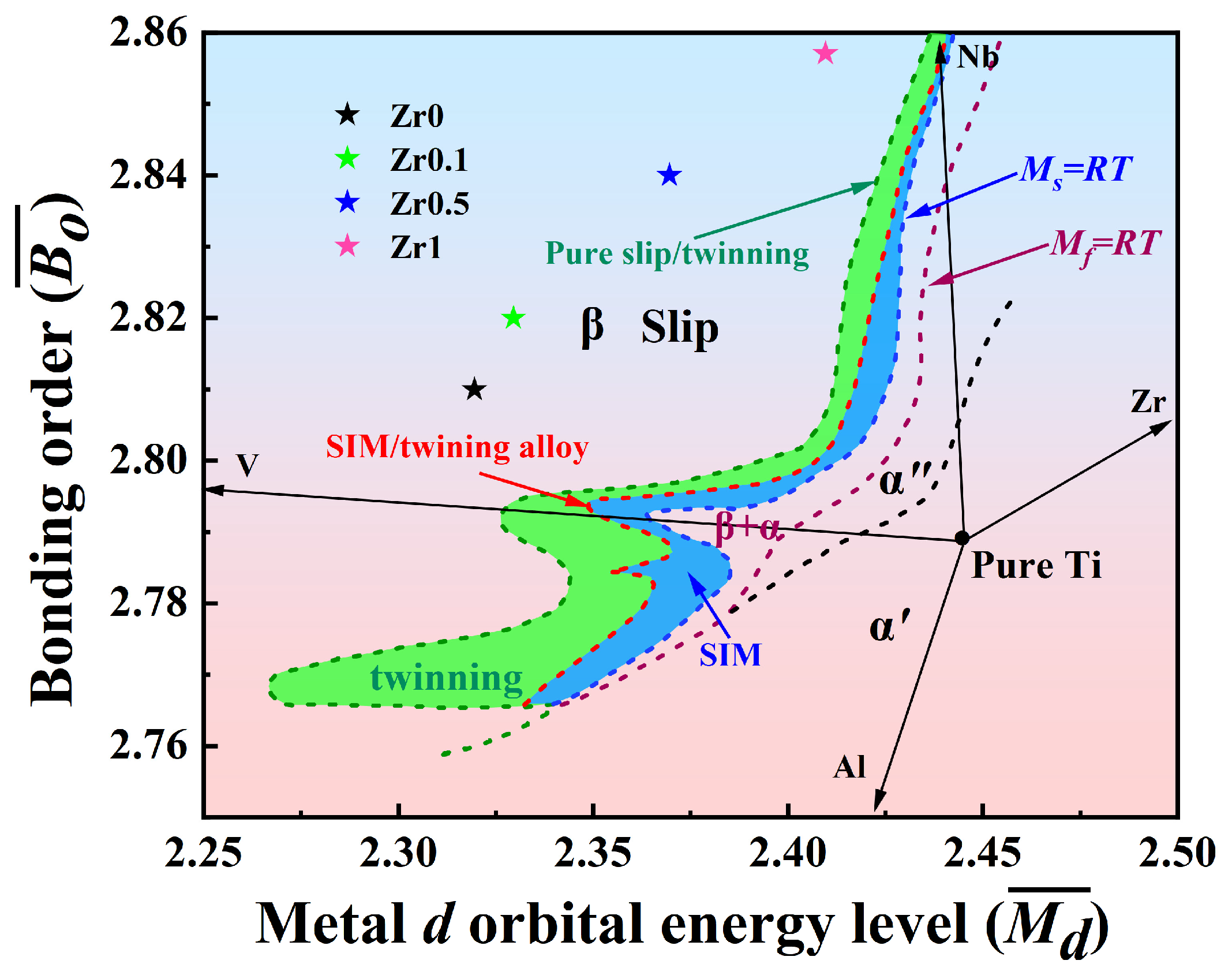
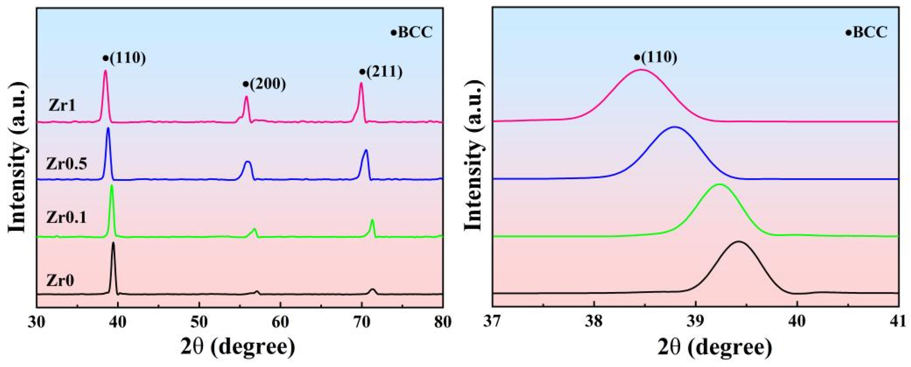
3.1. Phases and Alloys Design

The theoretical foundation of solid solution design is primarily based on thermodynamics and Hume–Rothery solid-solubility criteria, which encompass three key principles: the size effect rule, the electronegativity effect rule, and the relative valence effect rule.
It is known that alloys with small atomic radii differences, small electronegativity differences, and similar valences for each component are more likely to form solid solutions. In this study, Nb, Ti, V, Zr, and Al were selected to design LHEAs. Their fundamental properties are listed in Table 1. Al, Ti, and V exhibit similar atomic radii and low densities, ensuring lightweight characteristics. Zr exhibits a larger atomic radius and higher density compared with Al, Ti, and V, contributing to increased dislocation density for enhanced strength. Since Nb has a high melting point and density as well as good corrosion resistance, it could improve the corrosion resistance and high-temperature performance of these materials.
Previous studies have indicated that most LHEAs exhibit multiphase structures and may contain a variety of intermetallic compounds [20]. It is very easy to induce the formation of B2-type TiAl/ZrAl-ordered crystalline structure or C14 Laves phases, which form owing to the negative mixing enthalpy between Al and Ti/Zr elements (Table 2). These intermetallic compounds and ordered phases would lead to the deterioration of tensile plasticity at room temperature.
We next summarize the commonly used empirical parameters for predicting the phase formation of target alloys. These empirical parameters mainly include enthalpy of mixing (ΔHmix), entropy of mixing (ΔSmix), thermodynamic parameters (Ω), atomic radii difference (δ), electronegativity difference (Δχ), and valence-electron concentration (VEC) [21,22,23,24]. Their expressions are as follows:
Δ H m i x = i = 1 i j n 4 c i c j Δ H i j m i x
Δ S m i x = R c i ln   c i
Ω = T m Δ S m i x | Δ H m i x |
δ = i = 1 n c i 1 r i / i = 1 n c i r i 2
Δ χ = i = 1 n c i χ i i = 1 n c i χ i 2
V E C = i = 1 n c i V E C i
T m = i = 1 n c i T m
where R represents the molar gas constant; ci and cj represent the atomic percentages of the i-th and j-th elements, respectively; and n is the principal component of the alloy. Hij is the enthalpy of mixing between the i-th and j-th elements, and ri represents the atomic radius of element i. Tm is the melting point of the alloy calculated by the mixing law. χ i is the electronegativity of element i, and (VEC)i denotes the valence-electron concentration of element i. The ΔHmixδ criterion [21] suggests that in HEAs, when −15 kJ/mol < Δ H m i x < 5 kJ/mol and when 1% < δ < 6.6%, the alloy tends to form a disordered solid solution. The Ω–δ criterion [22] proposes that when Ω ≥ 1 and when the atomic mismatch δ ≤ 6.6%, the high-entropy alloy is more likely to form a single-phase solid solution structure. The valence-electron concentration (VEC) [23] can be used as another important parameter to predict the crystal structure. The statistical results show that when VEC ≥ 8.0, HEAs tends to form a single-phase FCC structure, and when 6.87 ≤ VEC < 8.0, the alloy tends to form dual-phase FCC + BCC structures. When VEC < 6.8, the alloy forms a single-phase BCC structure. VEC also has an effect on the mechanical properties of the alloy. When VEC < 4.5, the alloy exhibits enhanced intrinsic plasticity compared to conventional alloys [24]. Dong et al. [25] found that the formation of disordered solid solution is facilitated when χ < 11.7. This is because a large electronegativity difference facilitates the formation of intermetallic compounds [26]. We formulated the Ti3VNbAl0.5Zrx (x = 0, 0.1, 0.5, and 1) alloys by analyzing empirical parameters. All relevant empirical parameters are summarized in Table 3.
LHEAs [27] are defined as alloys with a density of less than 7 g/cm3. In this paper, the actual densities of the alloys are measured by Archimedes drainage method, and the theoretical density of the alloy is calculated by the mixing rule [28]. The calculation formula is as follows:
ρ = C i A i C i A i ρ i
where Ci, Ai, and i represent the atomic percentage, atomic mass, and the density of the i-th element, respectively. The experimental and calculated values of all four alloys’ densities are shown in Table 4.
Based on the molecular orbital calculation method of DV-Xα clusters, Morinaga et al. [29] proposed the d-electron theory to reveal the relationship between the stability of the β-phase and plastic deformation behavior. This method involves two main parameters, B o ¯ and M d ¯ . B o ¯ represents the overlap of electron clouds between atoms, and M d ¯ represents the combined effects of atomic size, electronegativity, and alloying. For multi-component Ti alloys, the average values of B o ¯ and M d ¯ can be calculated as follows [30,31,32]:
M d ¯ = X i · ( M d ) i
B o ¯ = X i · ( B o ) i
where ( M d ) i , ( B o ) i , and Xi are the M d and B o values and atomic percentage of each element in the alloy, respectively. The calculated values of B o ¯ and M d ¯ for the Ti3VNbAl0.5Zrx (x = 0, 0.1, 0.5, and 1) alloys are listed in Table 5.
Figure 1 shows the B o ¯ M d ¯ diagrams of the annealed Ti3VNbAl0.5Zrx (x = 0, 0.1, 0.5, and 1) alloys. The diagram is divided into three distinct regions, that is, α, α + β, and β by different boundary lines. Each region represents the possible phase structure and corresponds to different deformation mechanisms. According to the calculated results, all four alloys are located within the β-phase range. This indicates that the designed alloys exhibit a single-phase BCC structure and exhibit dislocation slip as the primary deformation mechanism.

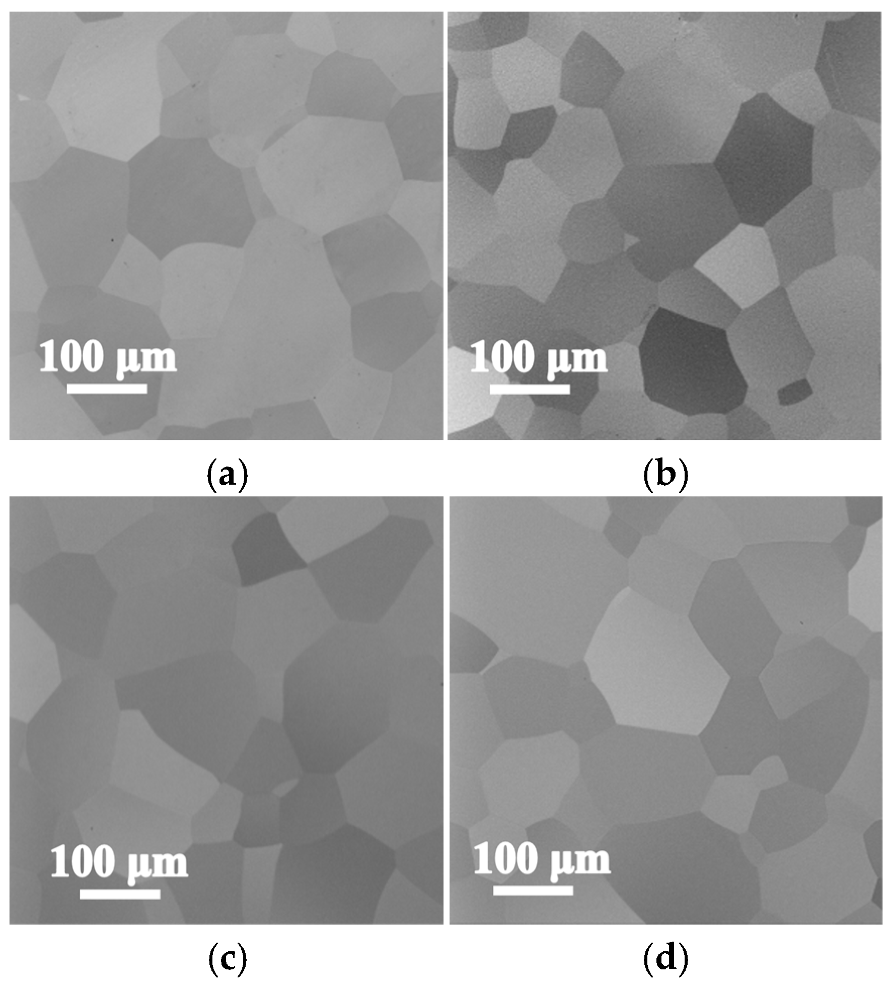
3.2. Microstructures and Phase Constitution of the Annealed Ti3VNbAl0.5Zrx Alloys

Figure 2 presents the XRD patterns of the annealed Ti3VNbAl0.5Zrx (x = 0, 0.1, 0.5, and 1) alloys. It can be seen that a single-phase BCC structure is identified for all compositions, with no secondary peaks detected. This confirms the B2 phases (commonly observed in Al/Zr-containing HEAs [33]) do not exist in all four alloys, demonstrating that it is an effective method to obtain a single-phase BCC structure by reasonably controlling the Zr/Al content. It can also be observed that with the increase in Zr content, the (110)BCC diffraction peaks shift towards lower diffraction angles, indicating an increase in lattice constant. According to the Bragg equation, the diffraction angle is negatively correlated with the lattice constant. As the change of Zr element content, the diffraction angle decreases and the lattice constant increases. The lattice parameters (Table 6) of Zr0, Zr0.1, Zr0.5, and Zr1 were calculated to be 3.219 Å, 3.237 Å, 3.279 Å, and 3.303 Å, respectively.
Figure 3 shows the SEM images of the annealed four alloys, revealing that all four alloys exhibit equiaxed crystals. The grain sizes (Table 6) of Zr0, Zr0.1, Zr0.5, and Zr1 are 124 μm, 101 μm, 120 μm, and 110 μm, measured by Imagepro software 6.0. EDS analysis revealed that no element segregation exists in these alloys.

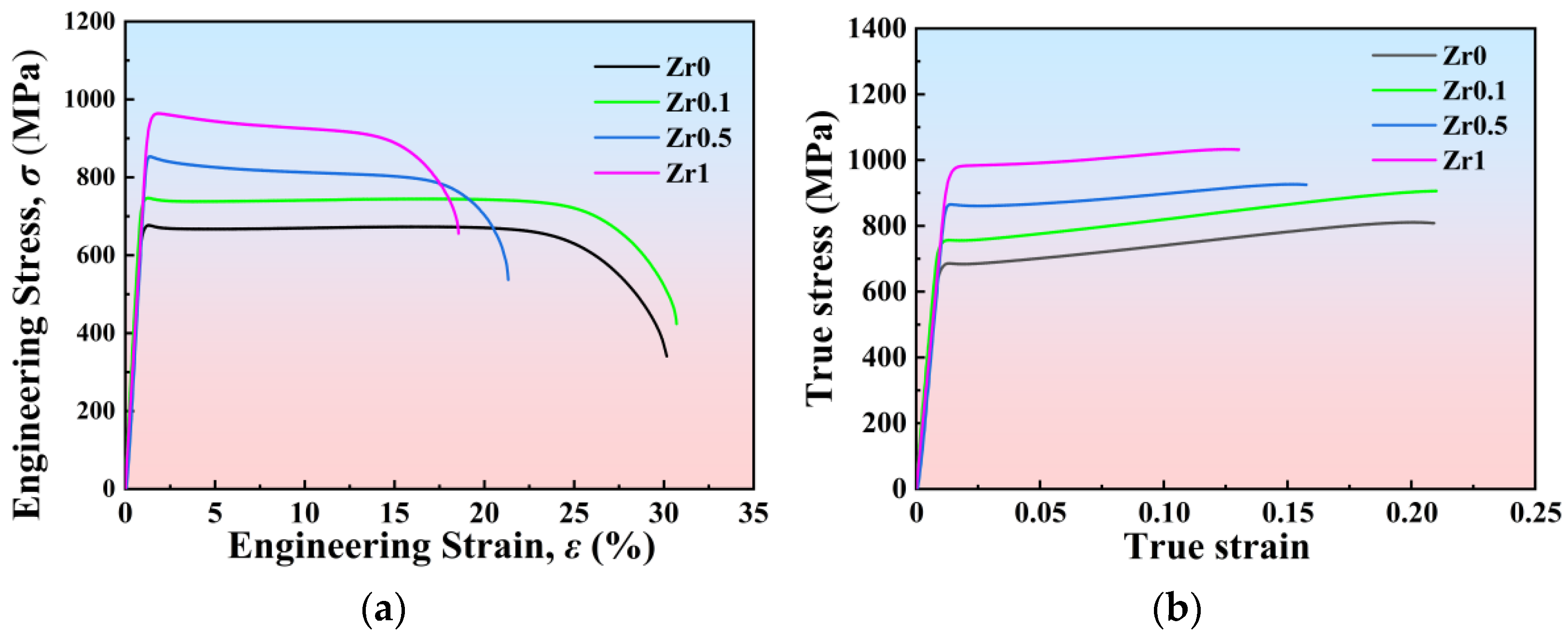
3.3. Tensile Properties of the Annealed Ti3VNbAl0.5Zrx Alloys

Figure 4a illustrates the tensile behavior of the annealed Ti3VNbAl0.5Zrx (x = 0, 0.1, 0.5, and 1) LHEAs at room temperature. It can be seen that all four alloys exhibit good tensile ductility. With the increase in Zr content from 0 to 1 at.%, there is a notable increase in the yield strengths in these alloys. The yield strengths of Zr0, Zr0.1, Zr0.5, and Zr1 alloys are 644 MPa, 703 MPa, 827 MPa, and 904 Mpa, respectively. With the increase in Zr content, the tensile strains of the four alloys exhibit a non-monotonic variation trend. When the Zr content is relatively low, the fracture strain increases. However, as the Zr content continues to increase, the tensile strains begin to decrease. The tensile strains of the Zr0, Zr0.1, Zr0.5, and Zr1 alloys are 29%, 30%, 20%, and 16%, respectively. For the Zr0.1 alloy, when a small amount of Zr element is added, the tensile elongation of the alloy does not change significantly, and the yield strength increases by about 60 MPa. The true stress–strain curves presented in Figure 4b show that all four alloys have weak work-hardening ability. This trend is similar to that observed in previously studied titanium alloys [34].
The specific strength is an important parameter to evaluate the mechanical properties of HEAs, which is defined as the ratio of yield strength to density. The densities of the Zr0, Zr0.1, Zr0.5, and Zr1 alloys are 5.39 g/cm3, 5.41 g/cm3, 5.47 g/cm3, and 5.68 g/cm3, respectively, which are significantly lower than those of most RHEAs. Figure 5 shows the relationship between specific yield strength and elongation for some previously reported RHEAs and LHEAs. With the addition of Zr, the specific yield strengths of the Zr0, Zr0.1, Zr0.5, and Zr1 alloys are 119 MPa·g−1·cm3, 130 MPa·g−1·cm3, 151 MPa·g−1·cm3, and 166 MPa·g−1·cm3, respectively. Obviously, the specific strengths exceed those of most reported RHEAs and LHEAs [35,36,37,38,39,40,41,42,43,44]. The excellent specific yield strength–plasticity synergistic effect of Ti3VNbAl0.5Zrx (x = 0, 0.1, 0.5, and 1) LHEAs indicates their great potential in the application of advanced structural materials.
Representative tensile fracture morphologies of the annealed four alloys are presented in Figure 6. It is clear that all four deformed samples exhibit similar ductile fracture characteristics, and the fracture surfaces all consist of a uniform distribution of dimples. The large amount of dimples indicates the great plastic deformation ability of the Ti3VNbAl0.5Zrx (x = 0, 0.1, 0.5, and 1) alloys.

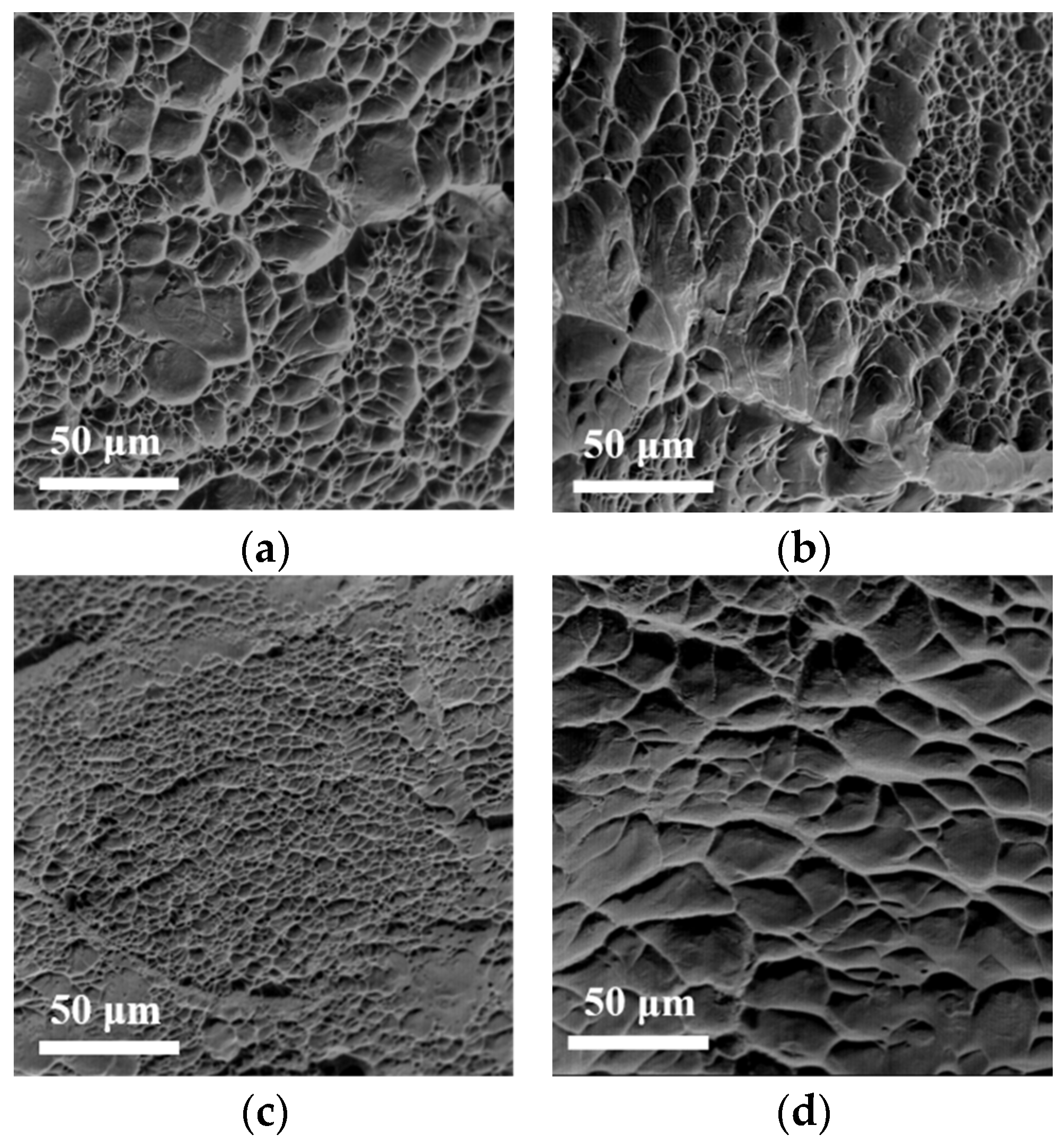
3.4. Microstructures of the Annealed Ti3VNbAl0.5Zrx Alloys After Tensile Deformation

It is known that dislocation interaction, phase transformation, or deformation twinning occurs normally during the plastic deformation of alloys. Among these, the phase transformation process mainly results from the structural instability. To confirm whether phase transformation occurs during tensile tests, XRD structural analysis was conducted on the samples after fracture. The corresponding XRD patterns in Figure 7 reveal that annealed Ti3VNbAl0.5Zrx (x = 0, 0.1, 0.5, and 1) alloys are still single-phase BCC structures after tensile deformation, suggesting that the BCC structure is stable during deformation.
TEM analysis was conducted to investigate the microstructure–deformation relationship in the studied Zr1 alloy. As shown in Figure 8a, the post-tension-annealed Zr1 alloy was analyzed via the selected area diffraction (SAED) pattern along the [001] zone axis, and neither phase transformation nor deformation twinning was detected during the deformation process, in agreement with the XRD results. Abundant dislocations were found to form dislocation networks, and there was an angle of 80 degrees between the double-slip bands, as shown in Figure 8b. Double slip enables dislocations to activate on two distinct slip systems, providing more slip paths for dislocation movement, effectively dissipating stress concentrations during plastic deformation, reducing local stress concentration, and improving the plastic deformation ability of Zr1 alloy.
In Figure 8c, the Taylor lattices are clearly visible. The Taylor lattice represents an arrangement of low-energy dislocation structures, and its presence is indicative of the dissipation of deformation energy. Along a specific slip plane, dislocations with alternating orientations (+dislocations and −dislocations) are present. These dislocations interact with each other, thereby reducing the stored energy and lattice distortion while facilitating enhanced dislocation mobility. Consequently, the alloy exhibits favorable room-temperature plastic deformation capability, albeit with a corresponding reduction in its work-hardening capacity. The Taylor lattice is composed of high-density dislocation walls (HDDWs), with regions of lower dislocation density surrounding these walls. HDDWs act as barriers to dislocation motion, causing localized dislocation accumulation and the development of complex tangles and loops. Figure 8d presents a large number of dislocation pile-ups near the grain boundary. Dislocation tangles, loops, and pile-ups collectively increase the resistance to dislocation movement, thereby stabilizing plastic deformation and enhancing the alloys’ yield strength [45,46,47].
Based on the results presented above, it can be concluded that dislocation slip is the main deformation mechanism of the Zr1 alloy, and dislocation interactions are key to achieving superior strength–ductility synergy.

4. Discussion

4.1. Deformation Mechanism of Annealed Ti3VNbAl0.5Zrx Alloys

The mechanical properties of β-Ti alloys under solution treatment conditions are governed by on their deformation modes, such as stress-induced martensite, mechanical twinning, and dislocation slip [4]. With increasing β-phase stability, the primary deformation mechanism of β-Ti alloys evolves from martensitic transformation to mechanical twinning and ultimately to dislocation glide. As shown in Figure 1, the four alloys maintain β-phase with single-phase BCC structures, and their dominant deformation mechanism is dislocation slip.
The B o ¯ M d ¯ diagram can reliably predict the two deformation mechanisms of dislocation slip and stress-induced martensite transformation. However, this method has a large error in predicting the formation of mechanical twins. As a step forward, Wang et al. [48] advanced the d-electron method by introducing two supplementary parameters other than B o ¯ and M d ¯ to predict the activation of twins, martensitic transformation, and dislocation slip. These parameters include average electron-to-atom ( e / a ¯ ) and the average atomic radius difference ( Δ r ¯ ) between each element and Ti element. The theory establishes that when e / a ¯ > 4.2, the deformation can only be carried out by dislocation slip. When e / a ¯ < 4.2 and Δ r ¯ > −2.5, mechanical twinning occurs. The ( e / a ¯ ) and radius difference ( Δ r ¯ ) are expressed as follows:
e / a ¯ = i n X i e i
Δ r ¯ = i n X i r i r T i
where X i is the atomic percentage of element i, r i represents the atomic radius of the i-th element, and r T i represents the atomic radius of Ti element. The calculation is carried out according to the numerical values of metal atom radii in the Pauling scale. The calculated values are listed in Table 7, while Figure 9 is the e / a ¯ Δ r ¯ diagram of Ti3VNbAl0.5Zrx (x = 0, 0.1, 0.5, and 1) alloys. Based on the results, All four alloys fall within the dislocation slip-dominated regime of the e / a ¯ Δ r ¯ diagram, with no detectable mechanical twinning or stress-induced martensitic transformation. This is consistent with the characterization results from XRD and TEM in Figure 7 and Figure 8.
To probe the influence of Zr content on the mechanical properties of the alloy, we quantified dislocation density via post-tensile XRD patterns (Figure 7) in the annealed Ti3VNbAl0.5Zrx alloys. The calculations of dislocation density were performed using the Williamson–Hall method, with the following expression [49]:
ρ = 2 3 ε / D b
where b is the Burgers vector, and D is the grain size. The strain ε was derived from the linear fit between the full width at half maximum (FWHM) of the XRD patterns and FWHM·cosθ and 4sinθ. The dislocation densities of the Zr0, Zr0.1, Zr0.5, and Zr1 are 4.8 × 10¹⁴ m−2, 5.1 × 10¹⁴ m−2, 5.4 × 10¹⁴ m−2, and 6.8 × 10¹⁴ m−2, respectively. Figure 10 correlates Zr content with dislocation density evolution and stress–strain responses.
The results of the analysis indicate a significant increase in dislocation density with the addition of Zr. This trend suggests that the incorporation of Zr enhances dislocation generation due to lattice distortion caused by Zr atoms. As the Zr content rises from 0 at.% to 0.1 at.%, limited Zr disrupts atomic ordering, increasing dislocation density and concurrently improving strength (644→703 MPa) and ductility (29→30%). However, as the Zr content rises from 0.5 at.% to 1.0 at.%, the excessive dislocation density triggers defect accumulation, including pile-ups, loops, and tangles. These defects hinder dislocation glide, increasing yield strength (827→904 MPa) and causing a reduction in ductility (20→16%).

4.2. Strengthening Mechanism of Annealed Ti3VNbAl0.5Zrx Alloys

The yield strength of the annealed Ti3VNbAl0.5Zrx (x = 0, 0.1, 0.5, and 1) alloys is calculated by combining the inherent yield strength and several strengthening mechanisms, as expressed by the following equation [50]:
σ c a l = σ m i x + Δ σ g + Δ σ s
where σ c a l represents the calculated value of yield strength, σ m i x represents the inherent yield strength of the alloys, Δ σ g is the grain boundary strengthening, and Δ σ s is the solid solution strengthening. σ m i x is calculated using the mixing rule:
σ m i x = i = 1 n c i σ y i
where c i and σ y i are the atomic ratio and yield strength of i-th element. Elemental properties (atomic radius R, shear modulus G, and yield strength σy) are listed in Table 8. The σ m i x values of Zr0, Zr0.1, Zr0.5, and Zr1 alloys were calculated to be 125 MPa, 126 MPa, 132 MPa, and 138 MPa, respectively.
According to the Hall–Petch model, the contribution to the yield strength due to the grain boundaries strengthening can be expressed as follows:
Δ σ g = k h p d 1 / 2
where k h p represents the strengthening factor, and d represents the average grain diameter. In this study, we used the k h p value of the TiZrTaNbHf system, which was derived by Chen et al. [51] to be 270 MPa/μm1/2. The average grain sizes for Zr0, Zr0.1, Zr0.5, and Zr1 alloys are 124 μm, 101 μm, 120 μm, and 110 μm, respectively. Therefore, the strength increments Δ σ g of grain boundary strengthening were calculated to be 24 MPa, 27 MPa, 25 MPa, and 26 MPa, respectively.
Primarily, the classic solid solution strengthening model is utilized for dilute solution alloys. However, the unique chemical properties of HEAs impede the direct application of classical solid solution strengthening theories to these materials. Consequently, building upon the traditional solid solution strengthening models proposed by Labusch [52] and Fleischer [53], researchers [50] developed a novel solid solution strengthening model tailored for multi-principal HEAs. The individual solid solution strengthening contributions of each constituent element is calculated as follows:
Δ σ i = A G f i 4 / 3 c i 2 / 3
where A is a dimensionless constant, which is only related to the material, taken as 0.04 [54]. G represents the shear modulus of each element, and fi represents the mismatch parameter and can be expressed as follows:
f i = δ G i 2 + α 2 δ r i 2
where δ G i represents the shear modulus mismatch of element i, and δ r i represents the atomic size mismatch of element i. The α is a constant related to the type of moving dislocations and is equal to 9 typically. In the BCC lattice structure, the atomic coordination number is 8, forming a 9-atom cluster. Therefore, δ r i and α can be expressed by the following formula:
δ G i = 9 8 c j δ G i j
δ r i = 9 8 c j δ r i j
where c j represents the atomic percentage of the j-th element in the alloy; δ G i j and δ r i j represent the modulus difference and atomic size difference between elements i and j, respectively. They can be obtained by the following formula:
δ G i j = 2 G i G j / G i + G j
δ r i j = 2 r i r j / r i + r j
where Gi and Gj represent the shear modulus of elements i and j, and ri and rj represent the atomic size of elements i and j. The solid solution strengthening effect can be calculated by superimposing the individual solid solution strengthening contributions of each constituent element:
Δ σ s = Δ σ i 3 / 2     3 / 2
The calculated values of solid solution strengthening for the Zr0, Zr0.1, Zr0.5, and Zr1 alloys are 567 MPa, 592 MPa, 647 MPa, and 721 MPa, respectively.
Building on the earlier discussion, Figure 11 illustrates the strengthening contribution from the individual mechanisms to the yield strength in Ti3VNbAl0.5Zrx (x = 0, 0.1, 0.5, and 1) alloys. Upon comparing the calculated and experimental yield strengths of the alloys, discrepancies of 11%, 6%, 3%, and 2% were observed between the calculated and experimental data for the respective alloys. This deviation belongs to the confidence interval (27%) [50]. As the Zr content increases, the solid solution strengthening effect increases and plays a dominant role in the overall strengthening contribution.

5. Conclusions

In this work, a series of non-equiatomic Ti3VNbAl0.5Zrx (x = 0, 0.1, 0.5, and 1) alloys with an optimized balance of strength and ductility were designed and prepared. The microstructures, mechanical properties, deformation mechanisms, and strengthening mechanisms were studied, and the following conclusions can be drawn:
  • The four alloys were designed using the phase formation law and d-electron theory. By increasing the Ti content, controlling the content of Al and Zr elements, and adding the BCC structure-stabilizing element Nb, these methods effectively suppressed the formation of intermetallic compounds and B2 phases. The final results demonstrate that all the alloys successfully achieved a single-phase BCC structure;
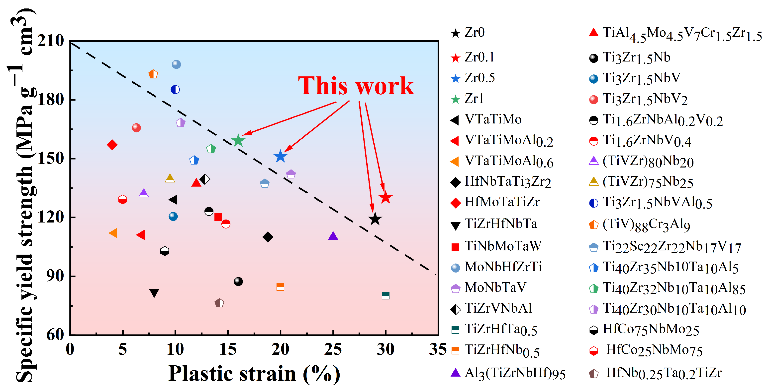
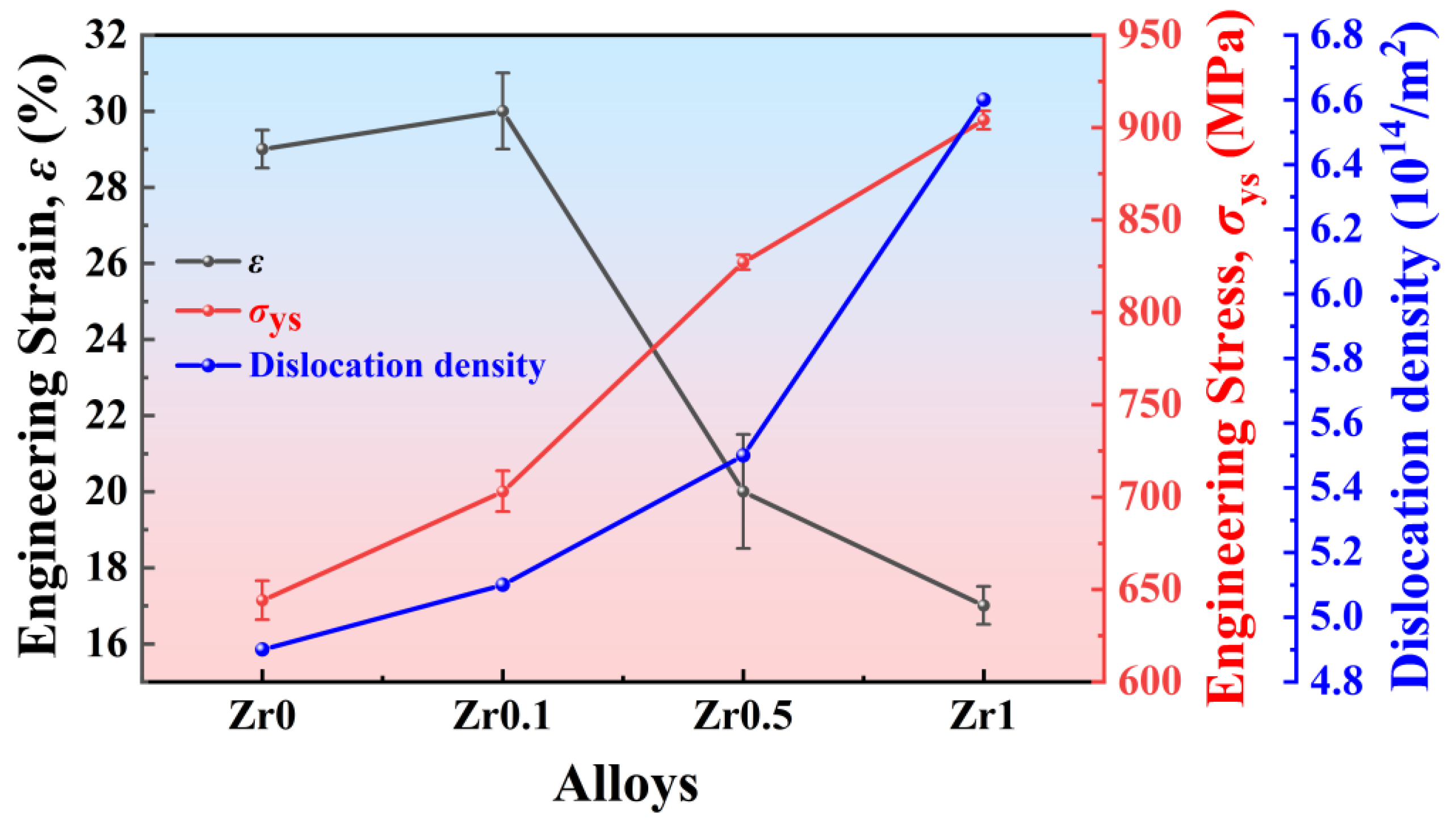
  • The yield strength of Ti3VNbAl0.5Zrx (x = 0, 0.1, 0.5, and 1) LHEAs increases significantly from 644 MPa (x = 0) to 904 MPa (x = 1). This substantial enhancement in yield strength is primarily attributed to the progressive increase in Zr content. However, the increase in Zr content also leads to a notable reduction in ductility, with ductility decreasing from 29% (x = 0) to 16% (x = 1). Additionally, it is observed that these alloys exhibit weak strain-hardening ability during the deformation process. Furthermore, the specific yield strength and tensile ductility of the Ti3VNbAl0.5Zrx LHEAs are better than those of most RHEAs and LHEAs;
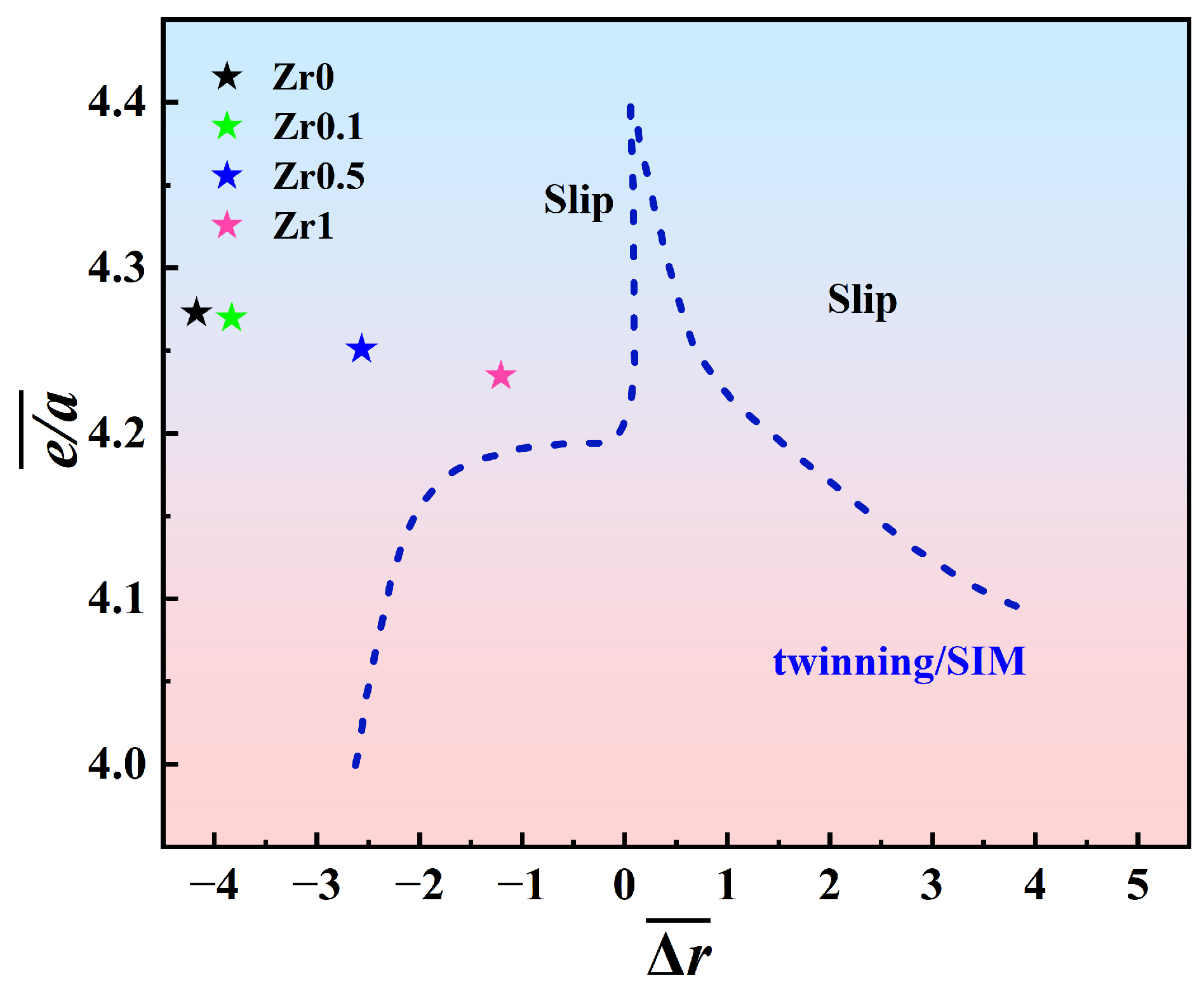
  • The deformation mechanism of Zr1 alloys is based on dislocation slip. The observation of deformation microstructure shows that the slip bands and Taylor lattices are the main deformation products in Zr1 alloy, which makes the alloy exhibit excellent tensile plasticity at room temperature. In addition, dislocation tangles, dislocation walls, dislocation loops, and dislocation pile-ups could also be observed. These substructures increase the resistance of dislocation movement and contribute to the stability of plastic deformation, thereby contributing to the weak strain-hardening ability of the alloys.

Author Contributions

Conceptualization, J.Q.; methodology, X.W., X.J., J.Q. and H.F.; validation, J.Q. and H.F.; formal analysis, H.F.; investigation, X.W., X.J., A.L. and H.F.; data curation, H.F.; writing—original draft preparation, H.F.; writing—review and editing, J.Q.; supervision, J.Q.; project administration, J.Q.; funding acquisition, X.W., X.J. and A.L. All authors have read and agreed to the published version of the manuscript.

Funding

This research was funded by the National Natural Science Foundation of China, Grant Number No. 12405316; the National Natural Science Foundation of China, Grant Number No. 52301217; and Natural Science Foundation of Shanxi Province, Grant Number No. 202203021221083.

Data Availability Statement

The original contributions presented in this study are included in the article. Further inquiries can be directed to the corresponding authors.

Acknowledgments

I would like to extend my sincere gratitude to all the instructors for their substantial contributions to research methodology, experimental design, data curation, manuscript writing, editing, and funding support. We are also grateful to the editors and reviewers for their valuable comments and suggestions, which have significantly enhanced the logic and rigor of this paper.

Conflicts of Interest

The authors declare no conflicts of interest.

Abbreviations

The following abbreviations are used in this manuscript:
BCCBody-centered cubic
LHEAsLightweight high-entropy alloys
RHEAsRefractory high-entropy alloys
HEAsHigh-entropy alloys
XRDX-ray diffraction
SEMScanning electron microscopy
EDSEnergy-dispersive spectroscopy
BSEBackscattered electron
TEMTransmission electron microscopy
SAEDSelected area diffraction
HDDWsHigh-density dislocation walls

References

  1. Bridges, D.; Fieser, D.; Santiago, J.J.; Hu, A. Novel Frontiers in High-Entropy Alloys. Metals 2023, 13, 1193. [Google Scholar] [CrossRef]
  2. Xiong, W.; Guo, A.X.; Zhan, S.; Liu, C.-T.; Cao, S.C. Refractory High-Entropy Alloys: A Focused Review of Preparation Methods and Properties. J. Mater. Sci. Technol. 2023, 142, 196–215. [Google Scholar] [CrossRef]
  3. Yeh, J.-W.; Chen, S.-K.; Lin, S.-J.; Gan, J.-Y.; Chin, T.-S.; Shun, T.-T.; Tsau, C.-H.; Chang, S.-Y. Nanostructured High-Entropy Alloys with Multiple Principal Elements: Novel Alloy Design Concepts and Outcomes. Adv. Eng. Mater. 2004, 6, 299–303. [Google Scholar] [CrossRef]
  4. Li, W.; Xie, D.; Li, D.; Zhang, Y.; Gao, Y.; Liaw, P.K. Mechanical Behavior of High-Entropy Alloys. Prog. Mater. Sci. 2021, 118, 100777. [Google Scholar] [CrossRef]
  5. Pandey, V.; Seetharam, R.; Chelladurai, H. A Comprehensive Review: Discussed the Effect of High-Entropy Alloys as Reinforcement on Metal Matrix Composite Properties, Fabrication Techniques, and Applications. J. Alloys Compd. 2024, 1002, 175095. [Google Scholar] [CrossRef]
  6. Yang, F.; Wang, J.; Zhang, Y.; Wu, Z.; Zhang, Z.; Zhao, F.; Huot, J.; Grobivć Novaković, J.; Novaković, N. Recent Progress on the Development of High Entropy Alloys (HEAs) for Solid Hydrogen Storage: A Review. Int. J. Hydrogen Energy 2022, 47, 11236–11249. [Google Scholar] [CrossRef]
  7. Arun, S.; Radhika, N.; Saleh, B. Advances in Vacuum Arc Melting for High Entropy Alloys: A Review. Vacuum 2024, 226, 113314. [Google Scholar] [CrossRef]
  8. Zhuo, L.; Xie, Y.; Chen, B. A Review on Recent Progress of Refractory High Entropy Alloys: From Fundamental Research to Engineering Applications. J. Mater. Res. Technol. 2024, 33, 1097–1129. [Google Scholar] [CrossRef]
  9. Senkov, O.N.; Wilks, G.B.; Scott, J.M.; Miracle, D.B. Mechanical Properties of Nb25Mo25Ta25W25 and V20Nb20Mo20Ta20W20 Refractory High Entropy Alloys. Intermetallics 2011, 19, 698–706. [Google Scholar] [CrossRef]
  10. Yu, B.; Ren, Y.; Zeng, Y.; Ma, W.; Morita, K.; Zhan, S.; Lei, Y.; Lv, G.; Li, S.; Wu, J. Recent Progress in High-Entropy Alloys: A Focused Review of Preparation Processes and Properties. J. Mater. Res. Technol. 2024, 29, 2689–2719. [Google Scholar] [CrossRef]
  11. Wang, Z.; Chen, S.; Yang, S.; Luo, Q.; Jin, Y.; Xie, W.; Zhang, L.; Li, Q. Light-Weight Refractory High-Entropy Alloys: A Comprehensive Review. J. Mater. Sci. Technol. 2023, 151, 41–65. [Google Scholar] [CrossRef]
  12. Dou, B.; Pan, Y.; Liu, S.; Wang, B.; Cheng, B.; Wang, L.; Sun, S.; Xue, Y. Achieving Outstanding Strength-Ductility Matching in BCC Light-Weight High Entropy Alloys via High Content Ordered Nanoprecipitates. Mater. Sci. Eng. A 2024, 889, 145861. [Google Scholar] [CrossRef]
  13. Ren, K.; Liu, H.; Chen, R.; Tang, Y.; Guo, B.; Li, S.; Wang, J.; Wang, R.; Lu, F. Compression Properties and Impact Energy Release Characteristics of TiZrNbV High-Entropy Alloy. Mater. Sci. Eng. A 2021, 827, 142074. [Google Scholar] [CrossRef]
  14. Zhu, M.; Yao, L.; Liu, Y.; Zhang, M.; Li, K.; Jian, Z. Microstructure Evolution and Mechanical Properties of a Novel CrNbTiZrAlx (0.25 ≤ x ≤ 1.25) Eutectic Refractory High-Entropy Alloy. Mater. Lett. 2020, 272, 127869. [Google Scholar] [CrossRef]
  15. Yurchenko, N.; Panina, E.; Salishchev, G.; Stepanov, N. Structure and Mechanical Properties of Near-Eutectic Refractory Al-Cr-Nb-Ti-Zr High Entropy Alloys. IOP Conf. Ser. Mater. Sci. Eng. 2021, 1014, 012058. [Google Scholar] [CrossRef]
  16. Wang, H.; Chen, W.; Chu, C.; Fu, Z.; Jiang, Z.; Yang, X.; Lavernia, E.J. Microstructural Evolution and Mechanical Behavior of Novel Ti1.6ZrNbAl Lightweight Refractory High-Entropy Alloys Containing BCC/B2 Phases. Mater. Sci. Eng. A 2023, 885, 145661. [Google Scholar] [CrossRef]
  17. Gao, F.; Deng, C.; Sun, Y.; Hu, L.; Ba, M. Lightweight Refractory High Entropy Alloys with Excellent Specific Strength and Enhanced Malleability by In-Situ Heterogeneous Structure. Mater. Charact. 2023, 203, 113127. [Google Scholar] [CrossRef]
  18. Qiao, D.; Liang, H.; Wu, S.; He, J.; Cao, Z.; Lu, Y.; Li, T. The Mechanical and Oxidation Properties of Novel B2-Ordered Ti2ZrHf0.5VNb0.5Alx Refractory High-Entropy Alloys. Mater. Charact. 2021, 178, 111287. [Google Scholar] [CrossRef]
  19. Soni, V.; Gwalani, B.; Alam, T.; Dasari, S.; Zheng, Y.; Senkov, O.N.; Miracle, D.; Banerjee, R. Phase Inversion in a Two-Phase, BCC+B2, Refractory High Entropy Alloy. Acta Mater. 2020, 185, 89–97. [Google Scholar] [CrossRef]
  20. Yurchenko, N.Y.; Stepanov, N.D.; Shaysultanov, D.G.; Tikhonovsky, M.A.; Salishchev, G.A. Effect of Al Content on Structure and Mechanical Properties of the AlxCrNbTiVZr (x = 0; 0.25; 0.5; 1) High-Entropy Alloys. Mater. Charact. 2016, 121, 125–134. [Google Scholar] [CrossRef]
  21. Heydari, H.; Tajally, M.; Habibolahzadeh, A. Calculations to Introduce Some Light High Entropy Alloys Based on Phase Formation Rules. J. Alloys Compd. 2022, 912, 165222. [Google Scholar] [CrossRef]
  22. Huang, R.; Tan, J.; Li, W.; Dong, Q.; Li, C.J.; Qin, X.M.; Guo, S.F.; Lu, Y.P. Effects of V Content on the Microstructure and Mechanical Properties of Nb31Ti37-Zr26Al6V Refractory Medium-Entropy Alloys. Intermetallics 2022, 143, 107472. [Google Scholar] [CrossRef]
  23. Li, Y.; Yang, J.; Yao, Z.; Zhao, W.; Fu, Y.; Jin, Z.; Dong, J.; Jin, L. Effect of Zr on Microstructure and Mechanical Properties of Novel Al0.5Mo0.5NbTi1.25V0.5Zrx Lightweight Refractory High-Entropy Alloys. J. Alloys Compd. 2025, 1024, 180085. [Google Scholar] [CrossRef]
  24. Feng, R.; Zhang, C.; Gao, M.C.; Pei, Z.; Zhang, F.; Chen, Y.; Ma, D.; An, K.; Poplawsky, J.D.; Ouyang, L.; et al. High-Throughput Design of High-Performance Lightweight High-Entropy Alloys. Nat. Commun. 2021, 12, 4329. [Google Scholar] [CrossRef]
  25. Dong, Y.; Lu, Y.; Jiang, L.; Wang, T.; Li, T. Effects of Electro-Negativity on the Stability of Topologically Close-Packed Phase in High Entropy Alloys. Intermetallics 2014, 52, 105–109. [Google Scholar] [CrossRef]
  26. Ma, Y.; Zhang, Y.; Zhang, Z.; Liu, L.; Sun, L. Two Novel Zr-Rich Refractory High-Entropy Alloys with Excellent Tensile Mechanical Properties. Intermetallics 2023, 157, 107872. [Google Scholar] [CrossRef]
  27. Cai, Z.; Guo, Y.; Liu, J.; Liu, J.; Guo, J.; Du, X.; Huang, S. Progress in Light-Weight High Entropy Alloys. J. Wuhan Univ. Technol.-Mat. Sci. Ed. 2021, 36, 737–753. [Google Scholar] [CrossRef]
  28. Heydari, H.; Tajally, M.; Habibolahzadeh, A. Computational Analysis of Novel AlLiMgTiX Light High Entropy Alloys. Mater. Chem. Phys. 2022, 280, 125834. [Google Scholar] [CrossRef]
  29. Abdel-Hady, M.; Hinoshita, K.; Morinaga, M. General Approach to Phase Stability and Elastic Properties of β-Type Ti-Alloys Using Electronic Parameters. Scr. Mater. 2006, 55, 477–480. [Google Scholar] [CrossRef]
  30. Ng, C.H.; Bermingham, M.J.; Yuan, L.; Dargusch, M.S. Towards β-Fleck Defect Free Additively Manufactured Titanium Alloys by Promoting the Columnar to Equiaxed Transition and Grain Refinement. Acta Mater. 2022, 224, 117511. [Google Scholar] [CrossRef]
  31. Cui, S.; Liu, S.; Nie, J.; Chen, D.; Wu, X.; Qin, G.; Zhang, E. Design and Preparation of a Biomedical Titanium Alloy with Low Elastic Modulus and High Antibacterial Property Based on Ti-Mo-Ag System. J. Alloys Compd. 2022, 908, 164639. [Google Scholar] [CrossRef]
  32. Yang, J.K.; Zhang, C.L.; Zhang, H.; Li, J.; Zhang, J.Y.; Kuang, J.; Liu, G.; Sun, J. Spinodal Decomposition-Mediated Multi-Architectured α Precipitates Making a Metastable β-Ti Alloy Ultra-Strong and Ductile. J. Mater. Sci. Technol. 2024, 191, 106–121. [Google Scholar] [CrossRef]
  33. Liu, F.; Chen, S.; Wang, B.; Wang, L.; Xiao, Y.; Wang, L.; Sun, S.; Xue, Y. High Specific Yield Strength TiZrAlNbV High-Entropy Alloys via Coherent Nanoprecipitation Strengthening. Mater. Sci. Eng. A 2022, 861, 144346. [Google Scholar] [CrossRef]
  34. Zhao, Q.; Bolzoni, L.; Chen, Y.; Xu, Y.; Torrens, R.; Yang, F. Processing of Metastable Beta Titanium Alloy: Comprehensive Study on Deformation Behaviour and Exceptional Microstructure Variation Mechanisms. J. Mater. Sci. Technol. 2022, 126, 22–43. [Google Scholar] [CrossRef]
  35. Xu, Z.Q.; Ma, Z.L.; Wang, M.; Chen, Y.W.; Tan, Y.D.; Cheng, X.W. Design of Novel Low-Density Refractory High Entropy Alloys for High-Temperature Applications. Mater. Sci. Eng. A 2019, 755, 318–322. [Google Scholar] [CrossRef]
  36. Li, G.; Wu, Z.; Dong, Y.; Hu, Z.; Jia, Y.; Wu, S.; Mu, Y.; Sun, K.; Jia, Y.; Wang, G. Microstructures, Properties and Preparations of Lightweight Refractory High-Entropy Alloys: A Review. J. Mater. Res. Technol. 2025, 35, 3183–3204. [Google Scholar] [CrossRef]
  37. Zheng, W.; Lü, S.; Wu, S.; Chen, X.; Guo, W. Development of MoNbVTax Refractory High Entropy Alloy with High Strength at Elevated Temperature. Mater. Sci. Eng. A 2022, 850, 143554. [Google Scholar] [CrossRef]
  38. Wang, S.; Shu, D.; Shi, P.; Zhang, X.; Mao, B.; Wang, D.; Liaw, P.K.; Sun, B. TiZrHfNb Refractory High-Entropy Alloys with Twinning-Induced Plasticity. J. Mater. Sci. Technol. 2024, 187, 72–85. [Google Scholar] [CrossRef]
  39. Juan, C.-C.; Tsai, M.-H.; Tsai, C.-W.; Lin, C.-M.; Wang, W.-R.; Yang, C.-C.; Chen, S.-K.; Lin, S.-J.; Yeh, J.-W. Enhanced Mechanical Properties of HfMoTaTiZr and HfMoNbTaTiZr Refractory High-Entropy Alloys. Intermetallics 2015, 62, 76–83. [Google Scholar] [CrossRef]
  40. Wang, S.; Wu, M.; Shu, D.; Zhu, G.; Wang, D.; Sun, B. Mechanical Instability and Tensile Properties of TiZrHfNbTa High Entropy Alloy at Cryogenic Temperatures. Acta Mater. 2020, 201, 517–527. [Google Scholar] [CrossRef]
  41. Han, Z.D.; Luan, H.W.; Liu, X.; Chen, N.; Li, X.Y.; Shao, Y.; Yao, K.F. Microstructures and Mechanical Properties of Ti NbMoTaW Refractory High-Entropy Alloys. Mater. Sci. Eng. A 2018, 712, 380–385. [Google Scholar] [CrossRef]
  42. Guo, W.; Liu, B.; Liu, Y.; Li, T.; Fu, A.; Fang, Q.; Nie, Y. Microstructures and Mechanical Properties of Ductile NbTaTiV Refractory High Entropy Alloy Prepared by Powder Metallurgy. J. Alloys Compd. 2019, 776, 428–436. [Google Scholar] [CrossRef]
  43. Wu, Y.; Si, J.; Lin, D.; Wang, T.; Wang, W.Y.; Wang, Y.; Liu, Z.; Hui, X. Phase Stability and Mechanical Properties of AlHfNbTiZr High-Entropy Alloys. Mater. Sci. Eng. A 2018, 724, 249–259. [Google Scholar] [CrossRef]
  44. Huang, R.; Zhang, L.; Amar, A.; Liaw, P.K.; Wang, T.; Li, T.; Lu, Y. Achieving Excellent Uniform Tensile Ductility and Strength in Dislocation-Cell-Structured High-Entropy Alloys. Int. J. Plast. 2024, 181, 104079. [Google Scholar] [CrossRef]
  45. Huang, W.; Hou, J.; Wang, X.; Qiao, J.; Wu, Y. Excellent Room-Temperature Tensile Ductility in as-Cast Ti37V15Nb22Hf23W3 Refractory High Entropy Alloys. Intermetallics 2022, 151, 107735. [Google Scholar] [CrossRef]
  46. Dou, B.; Zhang, Y.; Chen, A.; Cui, J.; Li, B.; Chen, S.; Li, Y.; Liu, S.; Wang, X.; Wang, B.; et al. Grain Refinement Induced Dynamic Plasticity Improvement in Lightweight High Entropy Alloys. J. Alloys Compd. 2024, 997, 174968. [Google Scholar] [CrossRef]
  47. Zhang, Y.; Wang, H.; Zhu, Y.; Zhang, S.; Cheng, F.; Yang, J.; Su, B.; Yang, C. High Specific Yield Strength and Superior Ductility of a Lightweight Refractory High-Entropy Alloy Prepared by Laser Additive Manufacturing. Addit. Manuf. 2023, 77, 103813. [Google Scholar] [CrossRef]
  48. Wang, C.H.; Russell, A.M.; Cao, G.H. A Semi-Empirical Approach to the Prediction of Deformation Behaviors of β-Ti Alloys. Scr. Mater. 2019, 158, 62–65. [Google Scholar] [CrossRef]
  49. Liu, D.; Jin, X.; Guo, N.; Liaw, P.K.; Qiao, J.W. Non-Equiatomic FeMnCrNiAl High-Entropy Alloys with Heterogeneous Structures for Strength and Ductility Combination. Mater. Sci. Eng. A 2021, 818, 141386. [Google Scholar] [CrossRef]
  50. Zeng, S.; Zhou, Y.; Li, H.; Zhang, H.; Zhang, H.; Zhu, Z. Microstructure and Mechanical Properties of Lightweight Ti3Zr1.5NbVAlx (x = 0, 0.25, 0.5 and 0.75) Refractory Complex Concentrated Alloys. J. Mater. Sci. Technol. 2022, 130, 64–74. [Google Scholar] [CrossRef]
  51. Hong, C.; Lu, Y.H.; Zheng, H.B.; Li, Z.H.; Guo, G.J. Uniaxial Tensile Behaviors and Hall-Petch Relationship of Polycrystalline 316LN Stainless Steel via Molecular Dynamics Simulation. Comput. Mater. Sci. 2024, 244, 113195. [Google Scholar] [CrossRef]
  52. Labusch, R. A Statistical Theory of Solid Solution Hardening. Phys. Status Solidi B 1970, 41, 659–669. [Google Scholar] [CrossRef]
  53. Fleischer, R.L. Solution hardening by tetragonal dist ortions: Application to irradiation hardening in FCC crystals. Acta Metall. 1962, 10, 835–842. [Google Scholar] [CrossRef]
  54. Yang, L.; Xiong, K.; Jin, C.; Dai, H.; Wu, H.; Zhang, S.; He, J.; Wang, Y.; Mao, Y. Effects of Ti Content on the Tensile Ductility, Lattice Distortion and Mechanical Properties of VNbTaTi Refractory High-Entropy Alloys. J. Mater. Res. Technol. 2024, 30, 3886–3899. [Google Scholar] [CrossRef]
Figure 1. Extended B o ¯ M d ¯ diagram for the annealed Ti3VNbAl0.5Zrx (x = 0, 0.1, 0.5, and 1) alloys.
Metals 15 00503 g001
Figure 2. XRD patterns of the annealed Ti3VNbAl0.5Zrx (x = 0, 0.1, 0.5, and 1) alloys.
Metals 15 00503 g002
Figure 3. SEM images of the annealed Ti3VNbAl0.5Zrx (x = 0, 0.1, 0.5, and 1) alloys (a) Zr0 alloy, (b) Zr0.1 alloy, (c) Zr0.5 alloy, and (d) Zr1 alloy.
Metals 15 00503 g003
Figure 4. Tensile curves of the annealed Ti3VNbAl0.5Zrx (x = 0, 0.1, 0.5, and 1) alloys at room temperature. (a) Engineering stress–strain curves, (b) true stress–strain curves.
Metals 15 00503 g004
Figure 5. Comparison diagram between specific yield strength–ductility at room temperature of the annealed Ti3VNbAl0.5Zrx (x = 0, 0.1, 0.5, and 1) alloys with previous reported RHEAs and LHEAs.
Metals 15 00503 g005
Figure 6. SEM images of fracture surfaces of tensile samples of the annealed Ti3VNbAl0.5Zrx (x = 0, 0.1, 0.5, and 1) alloys. (a) Zr0 alloy, (b) Zr0.1 alloy, (c) Zr0.5 alloy, and (d) Zr1 alloy.
Metals 15 00503 g006
Figure 7. The XRD patterns of annealed Ti3VNbAl0.5Zrx (x = 0, 0.1, 0.5, and 1) alloys after fracture.
Metals 15 00503 g007
Figure 8. TEM results of the annealed Zr1 alloy after tensile deformation. (a) SAED pattern; (bd) bright-field TEM micrographs of dislocation substructure.
Metals 15 00503 g008
Figure 9. e / a ¯ r ¯ diagram for the annealed Ti3VNbAl0.5Zrx (x = 0, 0.1, 0.5, and 1) alloys.
Metals 15 00503 g009
Figure 10. Correlation between Zr content, tensile yield strength, strain, and dislocation density in annealed Ti3VNbAl0.5Zrx (x = 0, 0.1, 0.5, and 1) alloys.
Metals 15 00503 g010
Figure 11. The calculated and experimental yield stress values of the annealed Ti3VNbAl0.5Zrx (x = 0, 0.1, 0.5, and 1) alloys.
Metals 15 00503 g011
Table 1. Melting point, atomic radius, VEC, density, and electronegativity of Al, Ti, V, Nb, and Zr.
ElementMelting Point (°C)Atomic Radius (Å)VECDensity (g/cm3)Pauling Electronegativity
Al6601.4332.71.61
Ti16601.4644.511.54
V18901.3256.111.63
Zr18521.6046.491.33
Nb24681.4358.571.60
Table 2. The relationships among the mixing enthalpies of elements.
Hmix (kJ/mol)AlTiVNbZr
Al−30−16−18−44
Ti −220
V −14
Nb 4
Zr
Table 3. The empirical parameters for the annealed Ti3VNbAl0.5Zrx (x = 0, 0.1, 0.5, and 1) alloys.
AlloysΔHmix (kJ/mol)ΔSmix (J/Kmol)VECΔδΔΩΔχ
Zr0−8.3361.16 R4.2733.78%2.033.37
Zr0.1−8.3121.239 R4.274.09%2.394.98
Zr0.5−8.1891.237 R4.2514.92%2.727.65
Zr1−8.0631.418 R4.2355.7%39.47
Table 4. Experimental and theoretical densities of the annealed Ti3VNbAl0.5Zrx (x = 0, 0.1, 0.5, and 1) alloys.
AlloysExperimental Density (g/cm3)Theoretical Density (g/cm3)
Zr05.39 ± 0.035.37
Zr0.15.41 ± 0.045.40
Zr0.55.47 ± 0.025.49
Zr15.68 ± 0.045.70
Table 5. The values of B o ¯ and M d ¯ for the annealed Ti3VNbAl0.5Zrx (x = 0, 0.1, 0.5, and 1) alloys.
Alloy B o ¯ M d ¯
Zr02.702.38
Zr0.12.712.39
Zr0.52.742.43
Zr12.762.46
Table 6. Lattice constant values (α) and grain sizes (D) of annealed Ti3VNbAl0.5Zrx (x = 0, 0.1, 0.5, and 1) alloys.
Zr0Zr0.1Zr0.5Zr1
α (Å)3.219 ± 0.00053.237 ± 0.00633.279 ± 0.00683.303 ± 0.0091
D (μm)124 ± 12101 ± 8120 ± 13110 ± 13
Table 7. The values of e / a ¯ and Δ r ¯ for the annealed Ti3VNbAl0.5Zrx (x = 0, 0.1, 0.5, and 1) alloys.
Alloy e / a ¯ Δ r ¯ (%)
Zr04.273−4.36
Zr0.14.270−4.05
Zr0.54.251−2.91
Zr14.235−1.69
Table 8. Elemental properties for the annealed Ti3VNbAl0.5Zrx (x = 0, 0.1, 0.5, and 1) alloys.
PropertiesTiZr Nb V Al
R (Å)1.4621.6031.4291.3121.432
G (GPa)4535384725
σy (MPa)14020710515030
Disclaimer/Publisher’s Note: The statements, opinions and data contained in all publications are solely those of the individual author(s) and contributor(s) and not of MDPI and/or the editor(s). MDPI and/or the editor(s) disclaim responsibility for any injury to people or property resulting from any ideas, methods, instructions or products referred to in the content.

