Abstract
Additive friction stir deposition (AFSD) enables solid-state, layer-by-layer metal deposition, minimizing defects and elemental loss from melting. Consequently, AFSD is highly effective for manufacturing aluminum alloys. Systematic studies indicate that grain structure influences properties along different processing directions in AFSD aluminum alloys. Accordingly, this study used AFSD to fabricate an aluminum alloy wall and rigorously characterized its microstructure and mechanical properties in both the XOY plane (X direction) specimen and the YOZ plane (Z direction) specimen. Results demonstrate that AFSD-fabricated 6061 aluminum alloys exhibit refined grains. Microhardness tests revealed directional variation, with the YOZ plane (Z direction) specimens showing lower hardness. Tensile tests showed that the transverse direction (X direction) specimens had slightly higher tensile strength than the deposition direction (Z direction) specimens. This study offers theoretical guidance for optimizing AFSD metal fabrication and provides data supporting the broader adoption of AFSD-fabricated 6061 aluminum alloys.
1. Introduction
Aluminum alloys feature low density as well as high specific strength and stiffness compared to other materials. AA6061-T6(ASTM) aluminum alloy exhibits excellent ductility, enhanced electrical and thermal conductivity, and pronounced corrosion resistance. As a result, AA6061-T6 aluminum alloy sees widespread use in transportation, aerospace, and composite manufacturing. This broad adoption underscores its significant research relevance and practical importance [1]. Conventional subtractive manufacturing methods generate considerable waste and fail to provide the design freedom characteristic of additive manufacturing. Conversely, additive manufacturing utilizes only the necessary material, thereby minimizing waste, shortening production cycles, and improving efficiency. This approach empowers designers to create more flexible, innovative structures and to fabricate products with diverse dimensions and intricate geometries [2,3].
Additive manufacturing (AM), commonly known as three-dimensional (3D) printing or rapid prototyping, fabricates objects through a layer-by-layer process. It deposits thin material layers guided by digital 3D model data [4,5]. Additive manufacturing, according to the melting and solidification behavior of materials in the additive manufacturing process, can be divided into two categories: fusion-based additive manufacturing technology and solid-phase additive manufacturing technology [6]. Fusion-based additive manufacturing (AM) operates under inert-gas or vacuum conditions and employs high-energy heat sources—such as lasers, electron beams, plasma jets, and arcs—to selectively melt metallic feedstocks along predefined trajectories, enabling rapid melting–solidification cycles and layer-by-layer deposition of the desired component [7]. However, these repeated thermal cycles introduce a range of defects—including internal porosity, lack of fusion, gas pores, thermal cracks, elemental vaporization, and localized metallurgical flaws—that compromise part integrity [1]. These issues are particularly severe in lightweight alloys such as aluminum and magnesium: Their high thermal conductivity, low melting point, and large thermal expansion coefficient exacerbate post-deposition distortion and produce heterogeneous microstructures [8]. As summarized in Table 1 [8], solid-state AM operates without metal melting or solidification, thereby eliminating fusion-related defects—such as porosity, cracking, and elemental vaporization [9,10]—and overcoming the distortion and heterogeneous microstructure issues that plague fusion-based AM of lightweight alloys (Al, Mg, and Ti). Consequently, solid-state AM offers distinct advantages for fabricating lightweight alloy structures, including enhanced part integrity, uniform microstructure, and reduced thermal distortion [11,12,13,14,15]. The vigorous plastic flow and near-zero porosity strengthen interfacial bonding [16]. Moreover, AFSD (additive friction stir deposition)’s minimal feedstock consumption eliminates any requirement for pretreatment.

Table 1.
Comparison of characteristics between solid-phase AM and fusion-based AM techniques. Adapted from [8].
Perry M E J et al. [17] observed dynamic recrystallization at the interface between the substrate and deposited layer during AFSD. Subsequent electron backscatter diffraction (EBSD) and energy-dispersive X-ray spectroscopy (EDS) analyses revealed that the average grain size decreased markedly from 59.4 µm in the substrate to 4.9 µm in the deposited layer. This grain refinement results from continuous dynamic recrystallization driven by high shear strains, yielding a uniform, equiaxed, and weakly textured microstructure in the deposited layer. Phillips et al. [18] examined how processing parameters affect the mechanical properties of 6061 aluminum alloy components produced by additive friction stir deposition (AFSD). The hardness of the deposited material decreased by approximately 20% compared to the as-received feedstock. This reduction resulted from elevated temperatures and plastic deformation during processing, which induced dynamic recrystallization and precipitate dissolution. Across the processing window, hardness exhibited a consistent trend. Higher tool rotation speeds combined with lower traverse speeds increased deposit hardness through enhanced shear deformation and localized thermal effects, whereas lower rotation speeds or higher traverse speeds produced insufficient plastic deformation and reduced hardness.
In studies by Phillips et al. [19] on 5083 aluminum alloy and by Rivera et al. [20] on 2219 aluminum alloy, differences in tensile performance were observed between the deposition direction and the tool-travel direction. Phillips et al. [19] attributed these disparities to crystallographic texture, interfacial grain-size heterogeneity, and interlayer bonding defects, while Rivera et al. [20] offered no specific explanation. Lyu W et al. [21] systematically revealed the relationship between grain structure and tensile anisotropy of AFSD Al-Zn-Mg-Cu alloy. It was found that the components showed obvious anisotropies in different directions. Thus, the effect of grain structure on the anisotropy of friction stir deposited aluminum alloy needs further characterization and research, which will help to study the effect of the construction process of AFSD aluminum alloy on the microstructure development of aluminum alloy.
Collectively, these studies show that AFSD invariably produces severe plastic-deformation–driven grain refinement and dynamic recrystallization, accompanied by precipitate dissolution and the emergence of processing-dependent textures, all of which give rise to measurable directional differences in hardness and tensile behavior, and additive friction stir deposition (AFSD) technology remains at an exploratory stage, with most studies to date focusing on equipment integration, process optimization, and the influence of processing parameters on component formation. However, quantitative understanding of how AFSD-induced microstructural changes govern anisotropic mechanical behavior in AA6061-T6 is still underdeveloped.
In this work, AA6061-T6 walls were fabricated by AFSD and systematically compared with the as-received feedstock: X-ray diffraction (XRD) was used to quantify lattice-parameter contractions and peak broadenings; scanning electron microscopy (SEM) and electron backscatter diffraction (EBSD) mapped grain-size reduction, recrystallization fractions, and texture evolution; microhardness testing determined directional hardness gradients; and tensile tests along both the transverse (XOY plane) and deposition (YOZ plane) directions quantified strength and ductility anisotropy. By integrating these multi-modal data, explicit correlations among grain refinement, precipitate dissolution, texture development, and lattice strain are established, providing a comprehensive framework for tailoring AFSD processing to achieve targeted performance in AA6061-T6 components.
2. Materials and Methods
Commercial AA6061-T6 aluminum alloy extruded cylindrical bar stock (ASTM B209, nominal diameter: 24 mm), purchased from Alcoa Corporation, Pittsburgh, PA, USA, was used as the consumable feedstock. Deposition was carried out onto the AA6061-T6(ASTM) aluminum alloy substrate. The chemical composition of the feedstock material is presented in Table 2.
Table 2.
Chemical composition mass fraction of 6061 aluminum alloy material (mass fraction, %).
A schematic of the AFSD process (deposition and transverse directions) and a plan view of the processing steps are shown in Figure 1a,b, and the samples obtained with a height of 540 mm are shown in Figure 2. AA6061-T6 was processed using a solid-state friction stir deposition machine. The main AFSD process variables include the stirring tool rotational speed, traverse speed, and the feed rate of the aluminum alloy. The experimental parameters were a stirring tool rotational speed of 375 r/min, a traverse speed of 300 mm/min, and a feed rate of 3000 mm/min for the aluminum alloy.
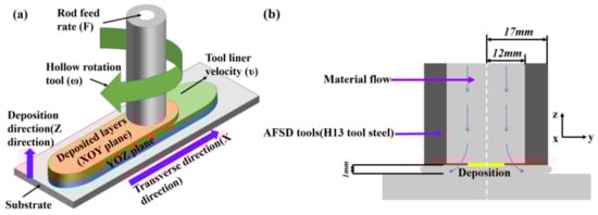
Figure 1.
Schematic diagram of AFSD process: (a) schematic illustration of the additive friction stir deposition (AFSD) process and (b) plan view of the AFSD process.
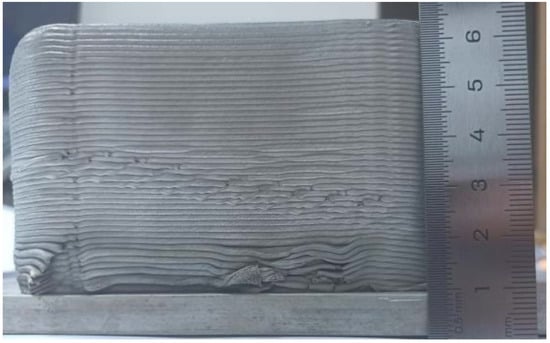
Figure 2.
AFSD 6061 aluminum alloy sample.
The microstructures of the base material (BM, AA6061-T6(ASTM)), AFSD (deposition direction and transverse direction) samples were quantitatively compared and analyzed, and the mechanical properties, including microhardness and tensile properties, were evaluated. The present work provides a pathway for solid-state additive manufacturing of light alloy parts.
This study examined samples from two processing planes: the YOZ plane (Z direction) and the XOY plane (X direction) to the AFSD path. Sample cross-sections were prepared via electrical discharge machining. Phases degrade aluminum alloy strength, toughness, ductility, and corrosion resistance while impairing surface quality and machinability. Phases were analyzed via an Empyrean X-ray diffraction (XRD) instrument (Malvern Panalytical, Almelo, The Netherlands) (20–90° scan range, 2°/min scan speed). To assess microstructural bonding, polished samples were etched with Kroll reagent before observation. Microstructural characterization was conducted via a Gemini 300 field-emission scanning electron microscope (FESEM; Carl Zeiss, Oberkochen, Germany). Grain, boundary misorientation, orientation, and texture were quantified via a Gemini SEM 300 field-emission scanning electron microscope equipped with an electron backscatter diffraction (EBSD) system (Carl Zeiss, Oberkochen, Germany). EBSD sampling is depicted in Figure 3a. The cut sample is shown in Figure 4a,b. After obtaining the EBSD analysis data, the Oxford Instruments OIM Analysis software (version 7.0; Oxford Instruments, Abingdon, UK) was used to randomly select five non-overlapping fields of view (each approximately 100 × 100 µm2 at 500× magnification) for each of the AFSD-X (XOY plane) and AFSD-Z (YOZ plane) specimens. In each field of view, the recrystallized, substructured, and deformed phases were classified by Grain Orientation Spread (GOS), and their area fractions were calculated.
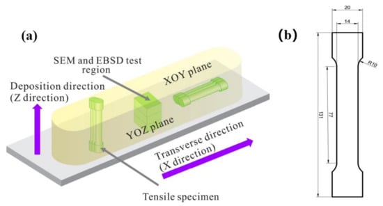
Figure 3.
(a) AFSD tensile specimen, EBSD specimen, and SEM specimen sampling location; (b) AFSD tensile specimen size (unit: mm).
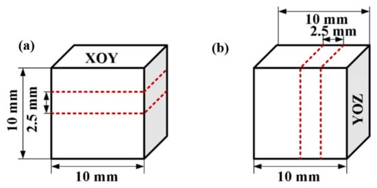
Figure 4.
(a,b) Test surface and sample size.
In accordance with the standard test methods of metallic materials [22], microhardness was measured with an FM-800 (Future Tech, Kawasaki, Japan) A 50 g load and 5 s dwell time were applied. Hardness was mapped across the YOZ plane (Z direction) and the XOY plane (X direction).
Rod-shaped tensile samples were extracted from AFSD specimens via electrical discharge machining. Sampling positions and dimensions are shown in Figure 3a,b. In accordance with the standard test methods for tension testing of metallic materials [23], tensile tests were conducted at room temperature on an SDS500 electro-hydraulic servo testing machine (Changchun Mechanical Science Research Institute Co., Ltd., Changchun, China) at a crosshead speed of 0.5 mm/min. Three specimens per direction were tested, and stress–strain curves recorded.
3. Results and Discussion
3.1. XRD Phase Analysis of Additive Samples
The X-ray diffraction (XRD) patterns of both the AA6061-T6 aluminum alloy (BM) and AFSD-processed samples in two processing directions are depicted in Figure 5a. The primary α-Al peaks corresponding to the (022), (200), and (311) planes dominate the XRD patterns of all three samples. In the XRD pattern of the BM specimen, weak diffraction peaks of the secondary phase Al5FeSi are also observed. After AFSD processing, the α-Al peaks remain pronounced. Table 3 records the 2θ position, dhkl, and the full width at half maximum (FWHM) of the (022), (200), and (311) main peaks.
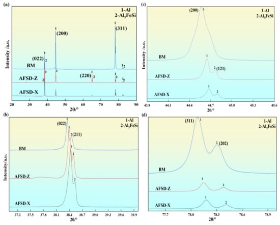
Figure 5.
XRD diffraction patterns of BM and AFSD with different construction directions: (a) XRD diffraction patterns, (b) the magnification of (022) peak, (c) the magnification of (200) peak, and (d) the magnification of (311) peak.
Table 3.
Variation in the 2θ location, FWHW, dhkl, and a of the diffraction peaks.
Compared with the AA6061-T6 Al alloy (BM), AFSD-Z and AFSD-X specimens show a systematic peak shift toward higher angles in the (022), (200), and (311) reflections. This shift corresponds to slight contractions in interplanar spacings and lattice constants: For the (022) plane, the interplanar spacing dhkl decreased from 2.3443 nm to 2.3419 nm in AFSD-Z and to 2.3401 nm in AFSD-X, while the lattice constant a contracted from 6.6306 nm to 6.6240 nm and to 6.6193 nm. Similar contraction trends were observed for the (200) and (311) planes. Meanwhile, the FWHM of the (311) peak narrows in the Z direction deposition (from 0.3430° to 0.0945°) compared to the BM, while in the X direction (0.0994°), it is slightly broader than in the Z direction but still lower than that of the BM [24]. Similar contraction trends were observed for the (200) and (022) planes. This disparity reflects directional thermo-mechanical coupling: Thermal accumulation in the Z direction promotes dynamic recovery and reduces internal strain [25], whereas uniform heat input in the X direction facilitates simultaneous dynamic recrystallization and dislocation accumulation, leading to moderate lattice distortion [25].
3.2. Microscopic Morphology of Samples in Different Construction Directions
After preparing AFSD samples in the two different orientations, the specimens were polished and then directly examined by scanning electron microscopy (SEM). The SEM images of AFSD samples in the XOY plane (X direction), the YOZ plane (Z direction), and AA6061-T6 Al alloy are shown in Figure 6a–c. The relative proportions of the elements were determined by energy-dispersive X-ray spectroscopy (EDS) point scans, as shown in Table 4, revealing that the white particles consist predominantly of Al, Fe, and Si. No pores or cracks were observed in the AFSD specimens, indicating that material flow during processing was uniform.
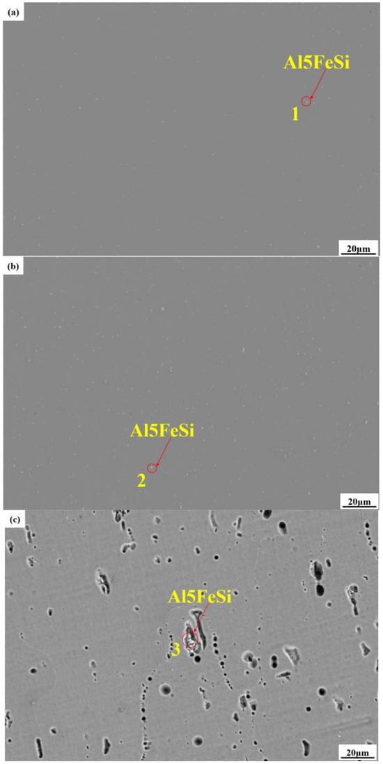
Figure 6.
Microscopic morphology of secondary phases in different construction directions of BM and AFSD: (a) the XOY plane (X direction) specimen, (b) the YOZ plane (Z direction) specimen, and (c) AA6061-T6 Al alloy specimen.
Table 4.
The element compositions corresponding to the regions marked in Figure 6 (at%).
The AFSD process reduces the size of the Al5FeSi phase. Figure 6a shows that the XOY plane (X direction) processing yields dispersed Al5FeSi particles. Conversely, the YOZ plane (Z direction) samples display aggregation of Al5FeSi particles. This aggregation reflects uneven heat input in the Z direction [26] and may impact performance. Figure 6c reveals larger Al5FeSi particles. During heat treatment of AA6061-T6 aluminum alloy in the production process, strengthening phases dissolve into the matrix; localized Fe and Si enrichment fosters the formation of Al5FeSi particles [25].
The XOY plane (X direction) equiaxed grains are shown in Figure 7a. Figure 7b displays equiaxed grains; however, compared to the X direction, the grains exhibit a varied distribution. Uniform grain distribution enhances mechanical properties [27]. During AFSD, the X direction undergoes intense frictional stirring, which induces plastic deformation and heating that trigger dynamic recrystallization [24], producing a homogenized equiaxed grain structure that promotes uniform mechanical properties. In contrast, uneven heat input during each deposition layer causes Z-direction specimens to experience complex thermal cycles and non-uniform plastic strains, leaving dynamic recrystallization incomplete in localized regions [28], which often correlates with reduced mechanical performance [29]. The AA6061-T6 aluminum alloy, which does not undergo the intense recrystallization characteristic of AFSD, exhibits lower plastic deformability than AFSD-deposited layers [30].
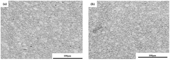
Figure 7.
Grain in different construction directions of AFSD: (a) the XOY plane (X direction) specimen and (b) the YOZ plane (Z direction) specimen.
3.3. EBSD Analysis
In the transverse XOY section (Figure 8(a-1)), intense plastic deformation and subsequent dynamic recrystallization reconstruct the microstructure: Equiaxed grains nucleate uniformly, and residual shear textures are removed. This is reflected in the {100} pole figure, which exhibits a strong cube component (peak = 9.1 MRD), while the {110} pole lacks any Goss ({110}<001>) intensity and the {111} pole shows only weak {111}<110>/{111}<112> fibers—clear evidence of full recrystallization and texture elimination [26]. By contrast, in the YOZ plane aligned with the deposition (Z) direction (Figure 8(b-1)), the {100} pole figure becomes more diffuse, while the {111}<110> and {111}<112> fiber components strengthen (peak = 4.2 MRD) alongside a faint Goss ({110}<001>) signature; this indicates ongoing shear-deformation effects in this orientation [26].
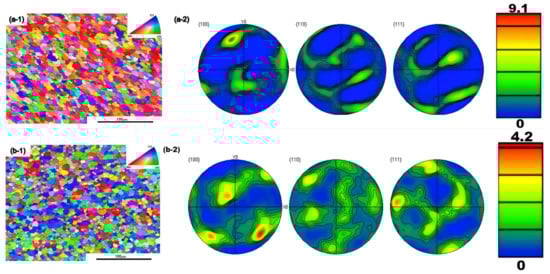
Figure 8.
Analysis diagram of EBSD samples with different construction directions in AFSD: (a-1,a-2) the XOY plane (X direction) specimens and (b-1,b-2) the YOZ plane (Z direction) specimens.
Cube texture delays fatigue crack nucleation and propagation along grain boundaries by promoting the formation of coincidence site lattice (CSL) boundaries while suppressing random high-angle grain boundaries; conversely, the Goss orientation lowers the fatigue crack initiation threshold by concentrating stress at grain boundaries [31,32]. Therefore, comprehensive performance optimization of AFSD AA6061-T6 aluminum alloy can be achieved by reinforcing cube texture in the XOY plane and suppressing Goss texture in the YOZ plane [27,33].
Recrystallization imaging of AA6061-T6 after AFSD processing (Figure 9) revealed grains predominantly at the triple junctions of grain boundaries in both X- and Z-oriented specimens, indicating extensive dynamic recrystallization. In the false-colored maps, blue grains indicate fully recrystallized areas, yellow grains denote subgrains, and red grains represent deformed grains. Under combined thermal–mechanical coupling during AFSD, plastic deformation induced dynamic recrystallization, allowing strain-free grains to replace original boundaries and form robust metallurgical bonds [34,35]. Notably, specimens in the XOY plane (X direction) exhibited more uniform and complete recrystallization, whereas the YOZ plane (Z direction) specimen—exposed to frequent interlayer thermal cycling and localized strain heterogeneity—showed subgrain-refined regions lacking full recrystallization [34,35].
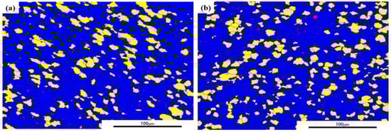
Figure 9.
Recrystallization diagram of AFSD in different construction directions: (a) the XOY plane (X direction) and (b) the YOZ plane (Z direction).
Quantitative analysis (Table 5) indicates that approximately 80.35% of grains in X direction specimens are fully recrystallized, with subgrains comprising 18.69% and deformed grains accounting for less than 1%. By contrast, Z-direction specimens exhibit 77.75% fully recrystallized grains, 21.24% subgrains, and just over 1% deformed grains. This difference confirms a higher degree of recrystallization and a more uniform microstructure in the X direction, correlating with lower residual stresses [28]. Mechanically, the higher fraction of recrystallized grains in the X direction should improve ductility and reduce defect sensitivity, whereas the increased subgrain fraction in the Z direction may slightly diminish overall ductility and fatigue life [36,37].
Table 5.
Recrystallization and deformation degree of samples in various directions after the AFSD process (mass fraction %).
3.4. Hardness Analysis
Microhardness testing, a simple and direct measure of mechanical performance, reflects microstructural features and indicates wear resistance in engineering applications. The resulting hardness contour map is shown in the Figure 10. In AFSD-fabricated 6061 aluminum, substrate hardness exceeds that of the deposited regions, and the substrate displays a uniform hardness profile without fluctuations, reflecting the AA6061-T6 Al alloy’s initial condition. Following solution treatment and aging, densely dispersed Mg2Si precipitates enhance hardness and strength, resulting in the substrate’s elevated initial hardness [38].
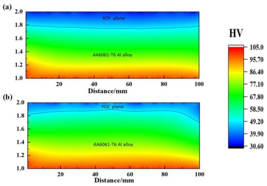
Figure 10.
Microhardness cloud maps of specimens with different construction planes: (a) the XOY plane and AA6061-T6 substrate specimens and (b) the YOZ plane and AA6061-T6 substrate specimens.
Microhardness profiles reveal a clear decrease in hardness from the as-rolled substrate into the AFSD-deposited region. This decline results from repeated high-temperature thermal cycles and plastic deformation during AFSD processing [26]. High-temperature thermal cycles during AFSD processing induce the redissolution of strengthening precipitates into the matrix, thereby weakening the precipitation-strengthening effect and ultimately reducing the overall hardness of the deposited zone [39,40]. Further comparison indicates that hardness on the XOY plane slightly exceeds that on the YOZ plane, primarily due to differences in the degree of dynamic recrystallization and thermal buildup [26,41]. During deposition, underlying layers experience repeated thermal cycling, which attenuates grain-refinement strengthening [34,35].
3.5. Tensile Performance
Tensile properties are fundamental for assessing a material’s mechanical performance. They provide essential insight into how microstructure influences mechanical behavior. Figure 11a shows the stress–strain curves of AA6061-T6 aluminum alloy and AFSD samples processed in the X and Z directions. Figure 11b presents the corresponding Ultimate Tensile Strength (UTS), Yield Strength (YS), and Elongation at Fracture (EL) values, allowing an intuitive comparison of the mechanical performance of AFSD-deposited material in the X and Z directions with that of the feedstock.
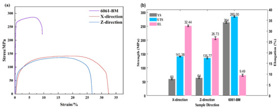
Figure 11.
(a) The stress–strain curves of specimens with different construction directions and AA6061-T6 aluminum alloy and (b) UTS, YS, and EL in all directions and AA6061-T6 aluminum alloy.
From the stress–strain curve in Figure 11a, the AA6061-T6 substrate exhibits a high tensile strength, with a stress of approximately 285 MPa. However, its elongation was low, at about 9.49%. The coexistence of high strength and low ductility—resulting in premature fracture during tensile testing—is attributed to the precipitation of the Mg2Si strengthening phase in the feedstock [39]. During AFSD, repeated thermal cycles can dissolve these precipitates in the AA6061-T6 material, reducing its strength [26]. In contrast, the AFSD-deposited material shows significantly lower tensile strengths in both X and Z directions. This decrease arises from changes in strengthening mechanisms during deposition [40] and from Mg2Si phase dissolution [42], which diminishes solid-solution strengthening. However, the AFSD-deposited material exhibits markedly improved ductility compared to the substrate. As shown in Figure 11b, elongation reaches approximately 32.44% in the X direction and approximately 26.73% in the Z direction, both well above the substrate’s 9.49%. This improvement is attributed to dynamic recrystallization during AFSD, which refines the grain structure and thereby enhances ductility [26].
The UTS of the AFSD-deposited material in the X direction is slightly higher than in the Z direction. During the AFSD process, the quality of interlayer bonding directly affects tensile behavior [41]; weaker interfacial cohesion can induce microcracks or localized stress concentrations [38], resulting in a lower UTS in the Z direction compared to the X direction. In terms of elongation, the EL in the X direction is markedly higher than in the Z direction, further indicating more uniform material flow in the X direction, whereas insufficient dynamic recrystallization may compromise ductility in the Z direction [38,41]. The 0.2%-offset yield strength (YS) of the AA6061-T6 alloy decreases from 264 MPa to 60 MPa in the AFSD-X direction and 64 MPa in the AFSD-Z direction, reflecting the near-complete dissolution of strengthening precipitates during solid-state deposition and the loss of solid-solution strengthening mechanisms [29,40]. Although the YS in the Z direction is slightly higher than in the X direction (64 MPa vs. 60 MPa), microstructural analysis shows that the X direction undergoes more extensive dynamic recrystallization—sustained frictional heating and plastic deformation produce equiaxed grains, enhancing ductility at the expense of yield strength [29,40].
3.6. Fracture Mode
The above tensile results demonstrate that, relative to the AA6061-T6 substrate, the deposited material exhibits lower strength and enhanced ductility in both the X and Z directions. The low-magnification fracture surface of the AFSD-X tensile specimen (Figure 12a) shows distinct shear lips and a cup-and-cone necking morphology. This indicates extensive plastic shear deformation before failure [26,42]. Higher-resolution imaging (Figure 12c) reveals homogeneous nucleation and coalescence of microvoids within the matrix, which act as primary crack initiation sites. Detailed examination (Figure 12e) reveals numerous deep, equiaxed dimples and tearing ridges, reflecting significant plastic elongation and localized strain concentration just before fracture [28].
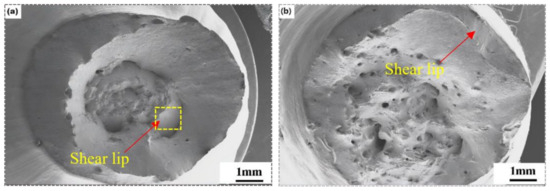
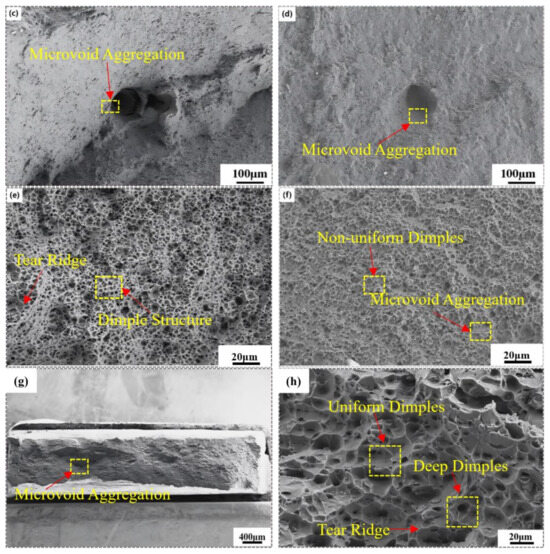
Figure 12.
(a,c,e) The transverse direction (X direction) tensile fracture, (b,d,f) deposition direction (Z direction) tensile fracture, and (g,h) AA6061-T6 aluminum alloy tensile fracture.
In the AFSD-Z tensile fracture surface, Figure 12b reveals a continuous array of shear lips around the periphery, indicating that the interlayer interface underwent extensive plastic deformation [26]. Microvoid coalescence observed in Figure 12d demonstrates that, during plastic deformation, voids nucleated uniformly within the matrix and merged to form the primary failure zone [26,42]. Furthermore, the presence of dimples of varying size and depth (Figure 12f) indicates that, although localized regions experienced severe plastic flow, the majority of plastic energy was concentrated at void coalescence sites, resulting in a lower elongation than in the X direction [28].
In the tensile fracture surface of the AA6061-T6 substrate, Figure 12g exhibits microvoid agglomeration, indicating that voids nucleated uniformly and coalesced into the principal failure zone during plastic deformation [26,41,42]. At Figure 12h, deep, uniformly equiaxed dimples and well-defined tearing ridges are visible. These features confirm that the material absorbed substantial plastic strain energy before fracture, characteristic of ductile failure [28].
4. Conclusions
- Variation in coherent diffraction domain size by AFSD: X-ray diffraction revealed that the coherent diffraction domain size in the AA6061-T6 substrate (60 nm) decreases to approximately 25 nm in the transverse (XOY) specimens and to 30 nm in the deposition (YOZ) specimens.
- Directional microstructural variation: SEM–EDS and EBSD analyses showed that the X-direction specimens feature uniformly dispersed Al5FeSi particles and a strong {100} <001> cube texture (peak MRD = 9.1), whereas the Z direction specimens exhibit aggregated secondary phases and a weaker preferred orientation (peak MRD = 4.2), reflecting the influence of shear deformation on texture development.
- Hardness distribution: Vickers microhardness mapping demonstrated that the AFSD-deposited regions possess lower hardness than the AA6061-T6 substrate, with the XOY plane exhibiting slightly higher values than the YOZ plane due to differences in dynamic recrystallization and thermal cycling effects, which influenced grain dimensions in the X and Z directions.
- Mechanical performance and anisotropy: Tensile testing showed that, relative to the substrate’s high strength (285 MPa) and low elongation (9.49%), AFSD-deposited material displays reduced tensile strength but markedly improved ductility (elongation of 32.44% in X direction and 26.73% in Z direction), with the X-direction specimens achieving marginally higher ultimate strength than Z-direction specimens owing to dynamic recrystallization and more uniform material flow. The YS in the Z direction is slightly higher than in the X direction (64 MPa vs. 60 MPa); microstructural analysis shows that the X direction undergoes more extensive dynamic recrystallization—sustained frictional heating and plastic deformation produce equiaxed grains, enhancing ductility at the expense of yield strength.
Author Contributions
Conceptualization, H.G., P.D. and Z.W.; methodology, H.G., P.D. and Z.W.; validation, H.G., P.D. and Z.W.; formal analysis, H.G., Z.W. and P.D.; investigation, H.G., P.D. and Z.W.; resources, P.D.; data curation, P.D.; writing—original draft preparation, H.G.; writing—review and editing, H.G., P.D. and Z.W.; visualization, P.D.; supervision, P.D.; project administration, P.D.; funding acquisition, P.D. All authors have read and agreed to the published version of the manuscript.
Funding
The authors are grateful for the financial support from the key R&D project plan of Shanxi Province (No. 202302150401001).
Data Availability Statement
The original contributions presented in this study are included in the article. Further inquiries can be directed to the corresponding author.
Conflicts of Interest
Author Peng Dong was employed by the company China State Shipbuliding Industry Group Fenxi Heavy Industry Co., Ltd. The remaining authors declare that the research was conducted in the absence of any commercial or financial relationships that could be construed as a potential conflict of interest.
References
- Gao, Q.W.; Zhao, J.; Shu, F.Y.; Lyu, C.C.; Qi, B.L.; Yu, Z.S. Research progress in aluminum alloy additive manufacturing. J. Mater. Eng. 2019, 47, 32–42. [Google Scholar] [CrossRef]
- Palanivel, S.; Mishra, R.S. Building without melting: A short review of friction-based additive manufacturing techniques. Int. J. Addit. Subtractive Mater. Manuf. 2017, 1, 82–103. [Google Scholar] [CrossRef]
- Labonnote, N.; Rønnquist, A.; Manum, B.; Rüther, P. Additive construction: State-of-the-art, challenges and opportunities. Autom. Constr. 2016, 72, 347–366. [Google Scholar] [CrossRef]
- Attaran, M. The rise of 3-D printing: The advantages of additive manufacturing over traditional manufacturing. Bus. Horiz. 2017, 60, 677–688. [Google Scholar] [CrossRef]
- Thomas, D. Costs, benefits, and adoption of additive manufacturing: A supply chain perspective. Int. J. Adv. Manuf. Technol. 2016, 85, 1857–1876. [Google Scholar] [CrossRef]
- Chen, G.; Wu, K.; Sun, Y.; Jia, H.; Zhu, Z.; Hu, F. Research progress in additive friction stir deposition. J. Mater. Eng. 2023, 51, 52–63. [Google Scholar] [CrossRef]
- Wang, H.M. Materials’ fundamental issues of laser additive manufacturing for high-performance large metallic components. Acta Aeronaut. Et Astronaut. Sin. 2014, 35, 2690–2698. [Google Scholar]
- Shi, L.; Li, Y.; Xiao, Y.; Wu, C.; Liu, H. Research progress of metal solid phase additive manufacturing based on friction stir. J. Mater. Eng. 2022, 50, 1–14. [Google Scholar] [CrossRef]
- Ghadimi, H.; Ding, H.; Emanet, S.; Talachian, M.; Cox, C.; Eller, M.; Guo, S. Hardness Distribution of Al2050 Parts Fabricated Using Additive Friction Stir Deposition. Materials 2023, 16, 1278. [Google Scholar] [CrossRef]
- Patil, S.M.; Krishna, K.M.; Sharma, S.; Joshi, S.S.; Radhakrishnan, M.; Banerjee, R.; Dahotre, N.B. Thermo-mechanical process variables driven microstructure evolution during additive friction stir deposition of IN625. Addit. Manuf. 2024, 80, 103958. [Google Scholar] [CrossRef]
- Li, W.Y.; Cao, C.C.; Yang, X.W.; Xu, Y.X. Cold spraying hybrid processing technology and its application. J. Mater. Eng. 2019, 47, 53–63. [Google Scholar] [CrossRef]
- Srivastava, A.K.; Kumar, N.; Dixit, A.R. Friction stir additive manufacturing—An innovative tool to enhance mechanical and microstructural properties. Mater. Sci. Eng. B 2021, 263, 114832. [Google Scholar] [CrossRef]
- Gopan, V.; Wins, K.L.D.; Surendran, A. Innovative potential of additive friction stir deposition among current laser based metal additive manufacturing processes: A review. CIRP J. Manuf. Sci. Technol. 2021, 32, 228–248. [Google Scholar] [CrossRef]
- Khodabakhshi, F.; Gerlich, A. Potentials and strategies of solid-state additive friction-stir manufacturing technology: A critical review. J. Manuf. Process. 2018, 36, 77–92. [Google Scholar] [CrossRef]
- Yu, H.Z.; Mishra, R.S. Additive friction stir deposition: A deformation processing route to metal additive manufacturing. Mater. Res. Lett. 2020, 9, 71–83. [Google Scholar] [CrossRef]
- Shen, Y.Z.; Zhou, Z.X.; Lv, W.C.; Guo, X.; Chen, X.; Wang, X. Research Progress on Solid-State Additive Friction Stir Deposition Manufacturing Technology. J. Nanjing Univ. Aeronaut. Astronaut. 2024, 56, 1–16. [Google Scholar] [CrossRef]
- Perry, M.E.; Griffiths, R.J.; Garcia, D.; Sietins, J.M.; Zhu, Y.; Yu, H.Z. Morphological and microstructural investigation of the non-planar interface formed in solid-state metal additive manufacturing by additive friction stir deposition. Addit. Manuf. 2020, 35, 101293. [Google Scholar] [CrossRef]
- Phillips, B.; Avery, D.; Liu, T.; Rodriguez, O.; Mason, C.; Jordon, J.; Brewer, L.; Allison, P. Microstructure-deformation relationship of additive friction stir-deposition Al–Mg–Si. Materialia 2019, 7, 100387. [Google Scholar] [CrossRef]
- Phillips, B.J.; Williamson, C.J.; Kinser, R.P.; Jordon, J.B.; Doherty, K.J.; Allison, P.G. Microstructural and Mechanical Characterization of Additive Friction Stir-Deposition of Aluminum Alloy 5083 Effect of Lubrication on Material Anisotropy. Materials 2021, 14, 6732. [Google Scholar] [CrossRef]
- Rivera, O.; Allison, P.; Brewer, L.; Rodriguez, O.; Jordon, J.; Liu, T.; Whittington, W.; Martens, R.; McClelland, Z.; Mason, C.; et al. Influence of texture and grain refinement on the mechanical behavior of AA2219 fabricated by high shear solid state material deposition. Mater. Sci. Eng. A 2018, 724, 547–558. [Google Scholar] [CrossRef]
- Lyu, W.; Shen, Y.; Huang, C.; Liu, F.; Wang, X.; Zhou, Z.; Chen, X.; Xia, Y.; Guo, X. Relationship between grain structure evolution and tensile anisotropy in Al-Zn-Mg-Cu cylindrical part formed by additive friction stir deposition. Mater. Sci. Eng. A 2024, 918, 1. [Google Scholar] [CrossRef]
- ASTM E384-17; Standard Test Method for Microindentation Hardness of Materials. ASTM International: West Conshohocken, PA, USA, 2017.
- ASTM E8/E8M-22; Standard Test Methods for Tension Testing of Metallic Materials. ASTM International: West Conshohocken, PA, USA, 2022.
- Zeng, C.; Ghadimi, H.; Ding, H.; Nemati, S.; Garbie, A.; Raush, J.; Guo, S. Microstructure Evolution of Al6061 Alloy Made by Additive Friction Stir Deposition. Materials 2022, 15, 3676. [Google Scholar] [CrossRef] [PubMed]
- Zhu, X.; Wang, R.; Wang, L.; Liu, M.; Li, S. Effect of Rotational Shear and Heat Input on the Microstructure and Mechanical Properties of Large-Diameter 6061 Aluminium Alloy Additive Friction Stir Deposition. Crystals 2024, 14, 581. [Google Scholar] [CrossRef]
- Chen, L.; Li, Y.; Lu, L.; Yang, Z.; Ren, X.; Zhang, X. The effect of heat treatment on the microstructure and mechanical properties of multilayer AA6061 alloy fabricated by additive friction stir deposition. Mater. Today Commun. 2024, 38, 108078. [Google Scholar] [CrossRef]
- Sridharan, N.; Gussev, M.; Seibert, R.; Parish, C.; Norfolk, M.; Terrani, K.; Babu, S.S. Rationalization of anisotropic mechanical properties of Al-6061 fabricated using ultrasonic additive manufacturing. Acta Mater. 2016, 117, 228–237. [Google Scholar] [CrossRef]
- Zhu, N.; Avery, D.Z.; Chen, Y.; An, K.; Jordon, J.B.; Allison, P.G.; Brewer, L.N. Residual Stress Distributions in AA6061 Material Produced by Additive Friction Stir Deposition. J. Mater. Eng. Perform. 2023, 32, 5535–5544. [Google Scholar] [CrossRef]
- Wells, M.C. Mechanical and Physical Properties in Additive Friction Stir Deposited Aluminum. Master’s Thesis, Virginia Tech, Blacksburg, VA, USA, 2022. Available online: http://hdl.handle.net/10919/111285 (accessed on 1 March 2025).
- Kinser, R.; Zhu, N.; Williams, M.; Rushing, T.; Doherty, K.; Allison, P.; Jordon, J. Effects on microstructure and mechanical properties of aluminum alloy 6061 processed via underwater additive friction stir deposition. J. Manuf. Process. 2025, 134, 932–942. [Google Scholar] [CrossRef]
- Kalinenko, A.; Kim, K.; Vysotskiy, I.; Zuiko, I.; Malopheyev, S.; Mironov, S.; Kaibyshev, R. Microstructure-strength relationship in friction-stir welded 6061-T6 aluminum alloy. Mater. Sci. Eng. A 2020, 793, 139858. [Google Scholar] [CrossRef]
- Khalfallah, A.; Azzeddine, H.; Baudin, T.; Brisset, F.; Huang, Y.; Langdon, T.G. Texture and microstructural evolution in an Al-6061 alloy processed by high-pressure torsion. Mater. Charact. 2024, 212, 114020. [Google Scholar] [CrossRef]
- Liu, W.; Wu, Y.; Deng, B.; Liu, A.; Liu, W.; Xu, Z.; Ye, T. Mechanical properties and microstructure of extruded 6061 aluminum alloy. Heat Treat. Met. 2020, 45, 172–177. [Google Scholar]
- Alam, C.S.; Karami, V.; Guo, S.; Rahman, M.S. Thermo-mechanical response of aluminum alloy in the additive friction-stir deposition process. Addit. Manuf. Lett. 2025, 12, 100263. [Google Scholar] [CrossRef]
- Stubblefield, G.; Fraser, K.; Phillips, B.; Jordon, J.; Allison, P. A meshfree computational framework for the numerical simulation of the solid-state additive manufacturing process, additive friction stir-deposition (AFS-D). Mater. Des. 2021, 202, 109514. [Google Scholar] [CrossRef]
- Modina, I.M.; Dyakonov, G.S.; Stotskiy, A.G.; Yakovleva, T.V.; Semenova, I.P. Effect of the Texture of the Ultrafine-Grained Ti-6Al-4V Titanium Alloy on Impact Toughness. Materials 2023, 16, 1318. [Google Scholar] [CrossRef] [PubMed]
- Tang, W.; Yang, X.; Tian, C. Influence of rotation speed on interfacial bonding mechanism and mechanical performance of aluminum 6061 fabricated by multilayer friction-based additive manufacturing. Int. J. Adv. Manuf. Technol. 2023, 126, 4119–4133. [Google Scholar] [CrossRef]
- Cheng, L.; Yang, X.; Tang, W.; Luo, T.; Wang, R. Processes and repair area properties of AA6061 repaired via additive friction stir deposition. Trans. China Weld. Inst. 2024, 45, 12–23. [Google Scholar] [CrossRef]
- Chen, L.; Lu, L.; Zhu, L.; Yang, Z.; Zhou, W.; Ren, X.; Zhang, X. Microstructure Evolution and Mechanical Properties of Multilayer AA6061 Alloy Fabricated by Additive Friction Stir Deposition. Met. Mater. Trans. A 2024, 55, 1049–1064. [Google Scholar] [CrossRef]
- Ghadimi, H.; Talachian, M.; Ding, H.; Emanet, S.; Guo, S. The Effects of Layer Thickness on the Mechanical Properties of Additive Friction Stir Deposition-Fabricated Aluminum Alloy 6061 Parts. Metals 2024, 14, 101. [Google Scholar] [CrossRef]
- Yang, F.; Pei, S.C.; Luo, X.R.; Chen, Y.X.; Li, N.Y.; Chang, Y.Q. Microstructure Evolution and Mechanical Properties of 6061 Aluminum Alloy Fabricated by Friction Stir Additive Manufacturing. Acta Metall. Sin. 2024, 1–18. [Google Scholar] [CrossRef]
- Chen, L.; Zhu, L.; Lu, L.; Yang, Z.; Ren, X.; Zhang, X. The effect of heat treatment on the microstructure and electrochemical corrosion behavior of multilayer AA6061 alloy fabricated by additive friction stir deposition. Appl. Surf. Sci. 2024, 650, 159167. [Google Scholar] [CrossRef]
Disclaimer/Publisher’s Note: The statements, opinions and data contained in all publications are solely those of the individual author(s) and contributor(s) and not of MDPI and/or the editor(s). MDPI and/or the editor(s) disclaim responsibility for any injury to people or property resulting from any ideas, methods, instructions or products referred to in the content. |
© 2025 by the authors. Licensee MDPI, Basel, Switzerland. This article is an open access article distributed under the terms and conditions of the Creative Commons Attribution (CC BY) license (https://creativecommons.org/licenses/by/4.0/).