Article

Impact of Heat Treatment on Microstructure Evolution in Grey Cast Iron EN-GJL-300

Faculty of Special Technology, Alexander Dubcek University of Trencin, Ku Kyselke 469, 911 06 Trencin, Slovakia
*
Author to whom correspondence should be addressed.
Metals 2025, 15(5), 530; https://doi.org/10.3390/met15050530
Submission received: 31 March 2025 / Revised: 2 May 2025 / Accepted: 6 May 2025 / Published: 8 May 2025

Abstract

This work investigated changes in the microstructure and local mechanical properties after the application of selected heat treatments to EN-GJL-300 grey cast iron. The main goal was to optimize heat treatment to achieve increased mechanical properties and subsequently wear resistance. The heat and heat–mechanical treatment were investigated by using a dilatometer as a physical simulator of treatment on real samples. Continuous cooling with three different rates and two other non-continuous treatments (austempering and ausforming) were used to treat the experimental samples. The research was focused on modification of the matrix microstructure, initially pearlitic. No change in the shape or morphology of the graphitic lamellae was required to preserve the damping properties. The results showed that, in terms of the specified conditions, heat treatment with continuous cooling at a rate of 10 °C s−1 appeared to be optimal. This variant showed the presence of bainite and martensite in the microstructure with high hardness measured by nanoindentation as well as the optimal value of general Brinell hardness.

1. Introduction

The presented research was applied on a part of lathe machine ways, where the main goal was to design and optimize the heat treatment of the part to increase its operating life. The part was made of grey cast iron with flake-shaped graphite. Grey cast iron has excellent damping properties, machinability, and thermal conductivity, where lamellar graphite also serves as a chip breaker [1]. Quenching and tempering are commonly used for ductile cast iron with nodular graphite [2], but in special cases, they could be applied also for grey cast iron. In the case of grey iron with a pearlitic matrix, quenching and tempering can be applied to transform the microstructure of the matrix to a bainitic or martensitic one. Several authors have studied the heat treatment of grey cast iron [3,4,5]. Heat treatment causes the microstructure change of the matrix, resulting in hardness increase and, consequently, elevated wear resistance.
Grey cast iron can be considered a heterogeneous multi-phase material in which the mechanical and functional properties are closely dependent on the morphology, distribution, and interfacial bonding between the carbon phase and metallic matrix. The stability of the graphite lamellae, as well as the kinetics of the phase transformations within the matrix, play a crucial role in determining the final performance of thermally processed components. Specific emphasis must be placed on diffusion-controlled and diffusionless transformation mechanisms, grain boundary mobility, and carbon redistribution during heat treatment. In particular, the transformation behavior under non-equilibrium conditions, such as during rapid cooling or isothermal holding, leads to the formation of complex microstructures involving bainitic ferrite, retained austenite, and even fresh martensite in selected cases.
The properties of grey cast iron can also be improved by non-continuous isothermal quenching, such as austempering (for bainite) or martempering (for martensite), as presented in [6,7,8]. Austempered grey iron (AGI) shows significantly enhanced mechanical properties and improved wear resistance under both dry and wet conditions compared to as-cast grey iron, as demonstrated by Navarro-Mesa et al. [9]. In austempering, iron is quenched from a temperature above the transformation range in a hot quenching bath and kept in the bath at constant temperature below the eutectoid temperature in the range from 260 to 400 °C (below the pearlite range but above the martensite range) until the austempering transformation is complete. Martempering is used to produce martensite without developing the high stresses that usually accompany its formation. It is similar to conventional hardening, except that distortion is minimized. The casting is quenched from above the transformation range in a salt, oil, or lead bath held in the bath at a temperature slightly above the range at which martensite forms (200 to 260 °C for unalloyed irons) only until the casting has reached the bath temperature; then, it is cooled to room temperature. The microstructure of grey cast iron after such heat treatment depends on the treatment parameters, i.e., on the temperature and duration of the austenitizing and of the isothermal quenching [7]. The microstructure after such heat treatment can also include atypical phases like acicular ferrite, since most of the ferritic platelets are nucleated around graphite flakes due to the high potential energy [10]. The grey cast iron manufactured by this treatment is called AGI (austempered grey cast iron). In addition, ausforming can be applied to heat treatment of grey iron. The process is like austempering, but the deformation is added to the isothermal tempering stage. The main purpose of the deformation application is the accelerated kinetics of the bainitic transformation [11]. Some authors have suggested that ausforming not only decreases the transformation rate but also reduces the final amount of bainite [12,13].
From a tribological point of view, the resulting microstructure significantly affects not only the hardness but also the surface integrity, crack propagation resistance, and residual stress profiles, especially in cyclically loaded applications. The interfacial interaction between retained austenite and harder transformation products such as martensite or bainite contributes to transformation-induced plasticity (TRIP) effects that can further influence the functional fatigue behavior [14].
Research on the heat treatment of ductile iron is preferred and widespread, while there is relatively less knowledge in the literature on the heat treatment of grey cast iron. Some authors investigated the heat treatment of grey cast iron and its benefit in increasing wear resistance [15,16,17]. Recent studies also point out the link between austempering parameters and not only strength but also fatigue resistance. Teng et al. [18] demonstrated that increasing the austempering temperature leads to coarser bainitic structures with higher retained austenite content, which results in a decrease in the tensile strength but an increase in the fatigue strength of AGI. The authors also proposed a quadratic relationship between the tensile and fatigue properties of cast irons.
The main goal of the research is to study several heat and heat mechanical treatments of the EN-GJL-300 to observe microstructure and consequently some changes in mechanical properties to increase their values with the benefit of increasing wear resistance as well. One of the tools that allows investigation of the changes in microstructure with respect to different heat treatment parameters is the dilatometric analysis. The dilatometer can be used to perform physical simulation of various heat treatments on real samples, where the key parameters (temperature, time) are computer controlled. Therefore, the sample is subjected to controlled heat treatment, and the resulting microstructure and its mechanical properties can be investigated.

2. Materials and Methods

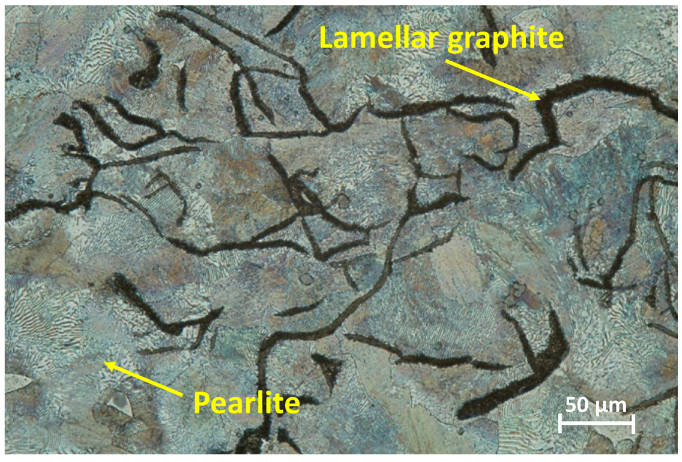
2.1. Experimental Material

The cast iron EN-GJL-300 used for experiment consists of flake graphite in a pearlite matrix in its as-delivered condition (Figure 1). Heating and subsequent cooling by different quenching rates can cause microstructure changes in the matrix and formation of the bainitic or martensitic structures.
The investigated grey cast iron has high compressive strength [19]. However, it has excellent casting ability, with mainly slight shrinking during casting. In addition, the mechanical properties are not favorable at high temperatures as a result of the higher carbon content. The chemical composition of the experimental cast iron EN-GJL-300, verified by optical atomic emission spectrometer SPECTROMAXx (LMX10, Kleve, Germany) is shown in Table 1. Its basic mechanical properties evaluated by standard tests are shown in Table 2.
A standard tensile test was performed to determine the tensile strength, yield strength, and elongation, where the values obtained from five samples were averaged [20]. The Brinell hardness measurement of experimental samples was performed, using a testing device with a loading of 500 N, for a specified period of time: t = 10 s, using a ball of 10 mm diameter hardened steel [21].

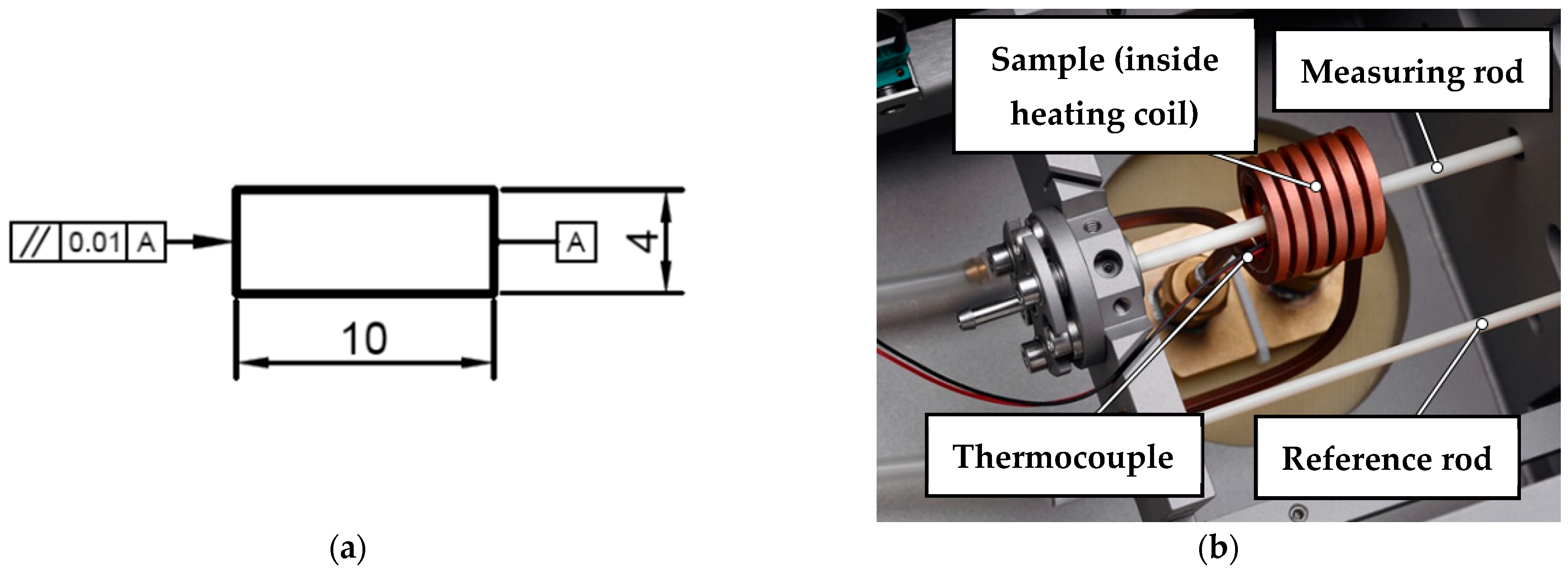
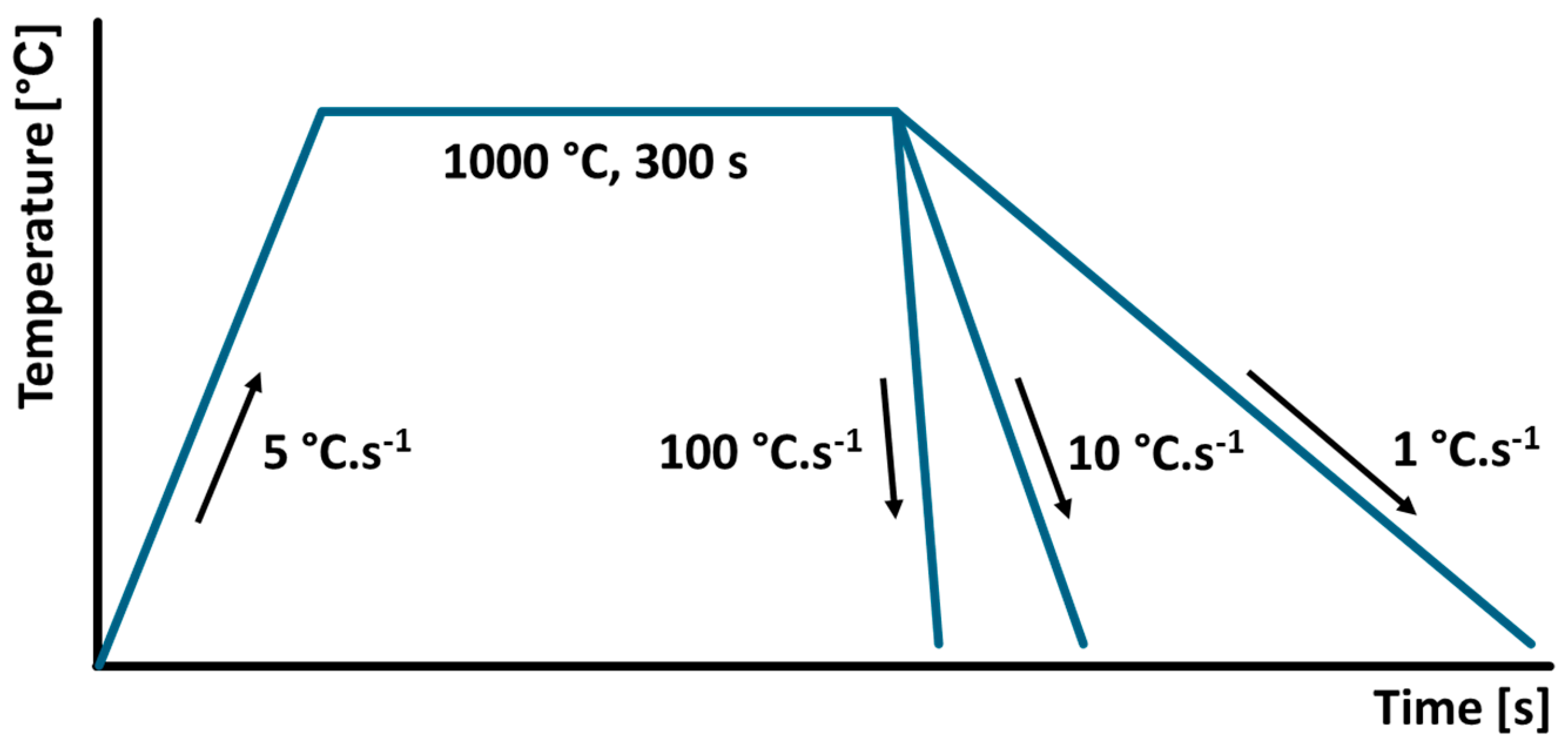
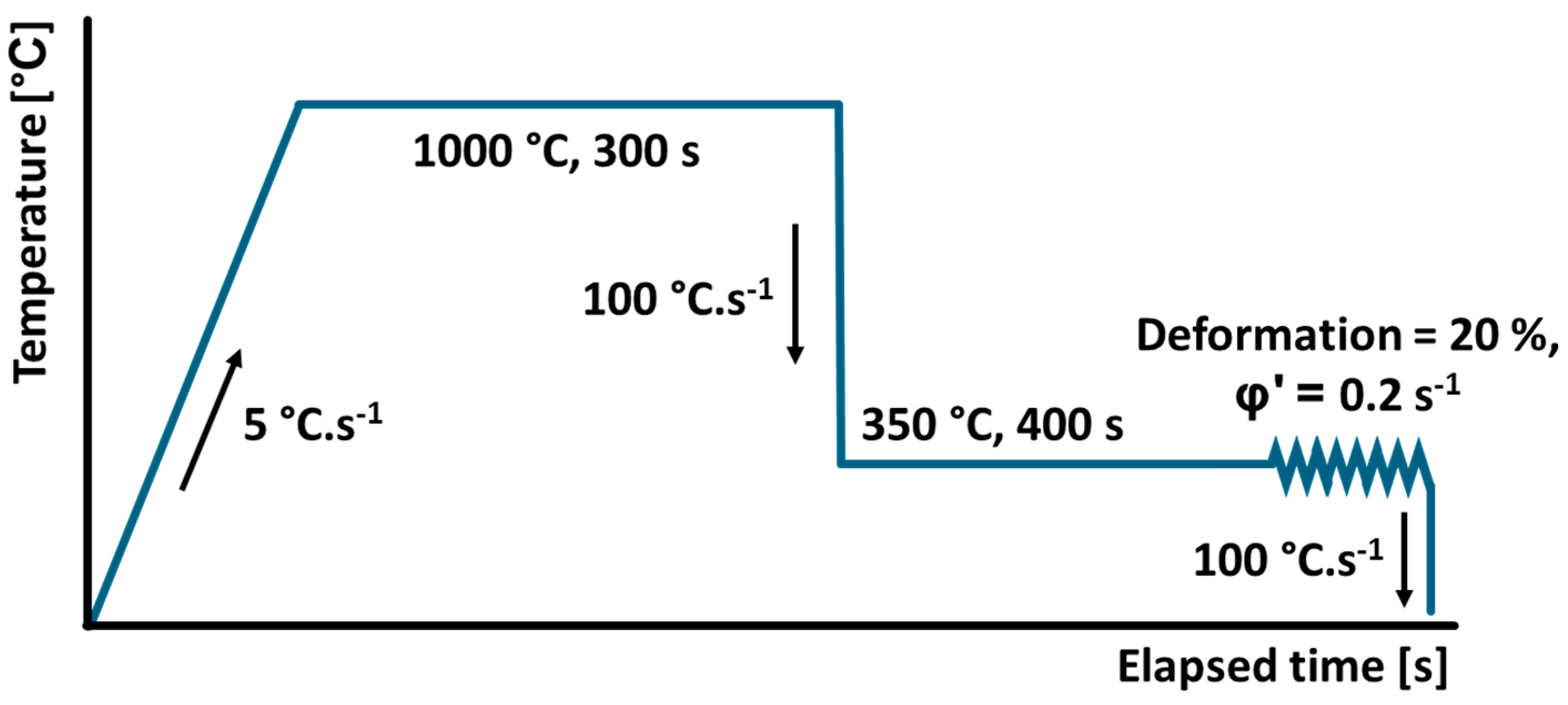
2.2. Heat Treatment of Experimental Samples

A dilatometer DIL805A was used to simulate the heat treatment of the samples in real conditions. The experimental sample required for treatment by the dilatometer and its basic dimensions are shown in Figure 2a. The sample was fixed between measuring rods and then inserted into the heating coil (Figure 2b). The coil was hollow and cooled by water during the measurement cooling cycle. The change in length was measured with the help of the reference rod. The temperature of the sample was measured by a thermocouple whose outputs were welded to the sample surface.
The sample was then subjected to the programmed thermal cycle. The heating stage of the cycle was performed by induction heating under vacuum and a cooling stage with helium as the protective and cooling gas. Equal parameters were used for all experimental samples during the heating stage, consisting of heating (5 °C s−1) to the austenitizing temperature (1000 °C) and a holding period at the temperature (300 s) to provide austenitizing in the sample volume. The austenitizing temperature was chosen under eutectic temperature, because even partial melting of the sample volume leads to dilatometric measurement failure.
Five different individual heat treatments were used to process the experimental samples. Samples 1 to 3 were cooled using continuous quenching by three different cooling rates (100 °C s−1, 10 °C s−1 and 1 °C s−1) from very fast to slow (Figure 3).
The last two samples were tested by an austempering- and ausforming-like process with a holding period on the tempering temperature of 350 °C. The heat treatment of sample 3 is shown in Figure 4. The last sample (4) was also tempered this way but was subjected to controlled deformation (Figure 5) with a degree of 20% and a rate of 0.2 s−1 at the end of tempering period.

2.3. Microstructure Analysis and Hardness Measurements

The microstructure of each experimental sample previously subjected to the specific thermal regime in dilatometer was subsequently observed by optical microscopy. The samples were treated by a standard metallographic procedure consisting of grinding, polishing, and etching by Nital (3% HNO3 in ethanol) to emphasize the microstructure. The microstructures were observed by confocal microscopy Olympus LEXT OLS 5100 (Olympus, Tokyo, Japan). After that, the Brinell hardness measurement of the experimental samples was carried out in accordance with the STN EN ISO 6506-1 standard [23] using a special testing device. During the measurement, a load of 500 N was applied to the sample, which lasted for 10 s. A hardened steel ball with a diameter of 10 mm was used as an indenter. This test was performed using a universal hardness tester Qness 250 CS evo (Qness GmbH, Hamburg, Germany). The impressions thus obtained were subsequently evaluated to determine the hardness of individual materials.

2.4. Quasistatic Nanoindentation

Quasistatic nanoindentation and SPM in situ scanning were performed on a Hysitron TI-950 measuring device (St. Minneapolis, MN, USA) equipped with Triboscan software (SPSS version 20.0). Nanoindentation tests were performed to determine the nanomechanical properties of some specific phases and structure constituents after different heat treatments of the experimental specimens. This method is mainly used in areas where it is necessary to evaluate the local mechanical properties (nanohardness, reduced Young modulus) of phases, structural components, or thin layers under microscopic magnification [24,25]. This cannot be measured by conventional methods of measuring mechanical properties such as Brinell, Vickers, Knoop, or Rockwell. These have a different geometry of test bodies and methodology of the indentation of one material into another, which include measuring the size of the resulting indentation geometry in the sample based on the applied load of the test body [24].
Quasistatic nanoindentation tests involve pushing a diamond tipped indenter head into a material under load and displacement control. Displacement (h) is monitored as a function of the load (F) throughout the load–unload cycle, where the resulting relation F-h is known as the nanoindentation curve. The plastic part of deformation is typically used to determine the Young’s Modulus, while the elastic–plastic part along with the indented surface are used to evaluate the hardness. The area bounded by both loading and unloading curves is equivalent to the dissipation energy [24]. The reduced modulus Er [Pa] was obtained from the initial unloading stiffness S [N·m−1]. The stiffness contact is then related to the reduced modulus Er according to Equation (1):
E r = π 2 β S A c ,
where β [m−1] is a constant which depends on the geometry of the used indenter, and Ac [m2] is the contact area of indentation [26]. The Berkovitch indenter loaded by a trapezoid loading curve was used during all the nanoindentations with a maximal load F = 10,000 µN and an indentation holding period t = 2 s.

3. Results and Discussion

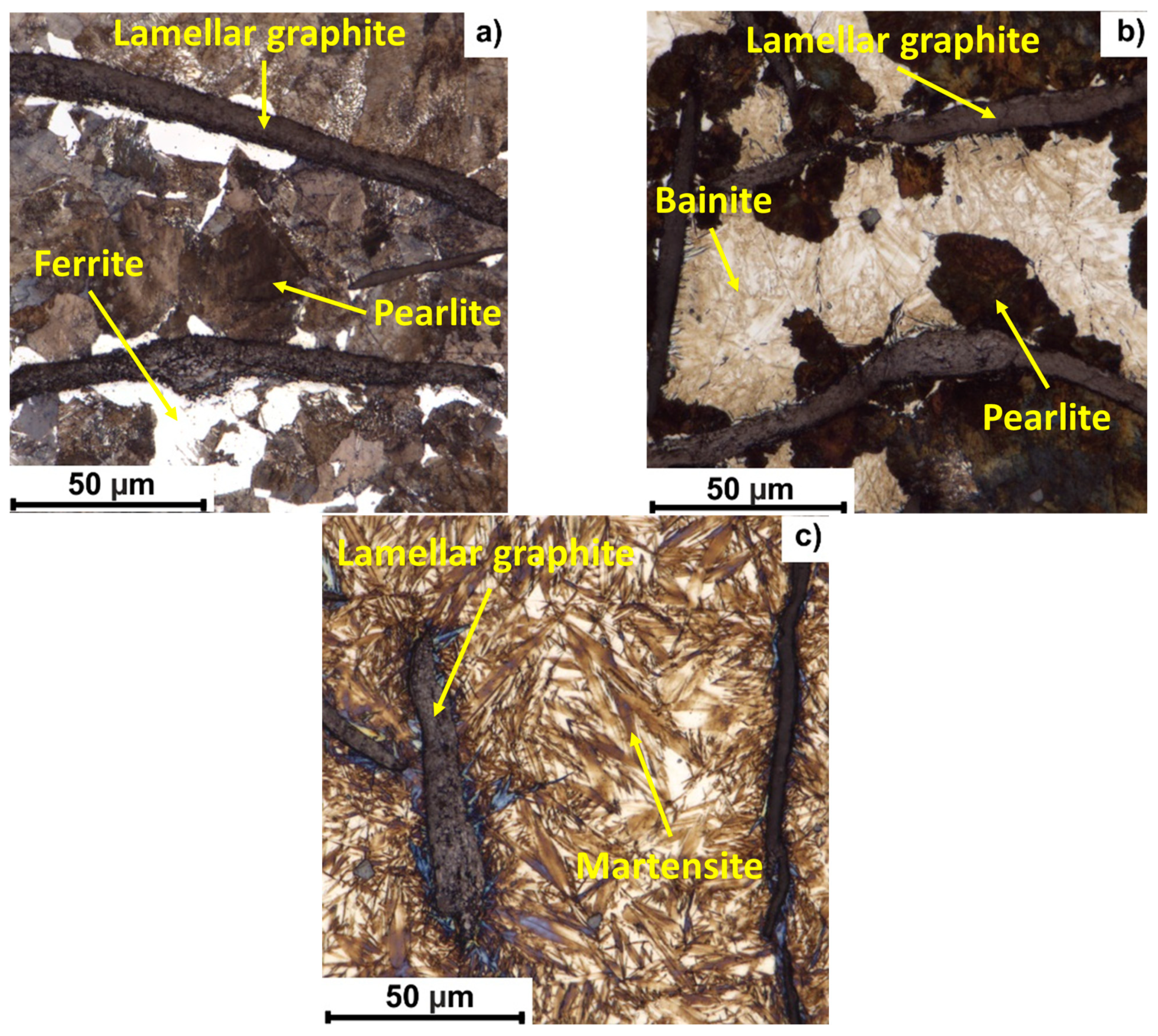
3.1. Evolution of Microstructure and Surface Hardness in Relation to the Heat Treatment

The microstructures observed after three different cooling rates are shown in Figure 6a–c. Figure 6a represents the microstructure after a very slow cooling rate (1 °C s−1). An inhomogeneous pearlitic matrix was observed in this case. Graphitic flakes are surrounded by a white ferritic area, which was later confirmed by nanoindentation of this phase. Figure 6b shows the microstructure after cooling at a rate of 10 °C s−1, including an assumed light grey bainitic region in the immediate vicinity of the flakes. Next, the microstructure (Figure 6c) was observed at very high cooling rate 100 °C s−1. As expected, the microstructure consists of martensitic needles and some retained austenite in the matrix surrounding graphite flakes. The formation of a homogeneous martensitic microstructure under rapid cooling is consistent with studies on Mn-alloyed steels designed for Q&P processes, where a wide temperature range between Ms and Mf enables flexibility in quenching strategies [27].
The microstructures acquired by austempering (Figure 7a) and ausforming (Figure 7b) are shown in Figure 7. In both cases, a needle-shaped microstructure was observed. Larger clusters of needles occur mainly at the interface of the graphite lamellae. Similar bainitic structures with increasing retained austenite and coarser acicular morphology at higher austempering temperatures were also observed in alloyed cast irons austempered in salt baths, where the mechanical properties and fracture mechanisms were shown to depend strongly on the morphology and fraction of the retained austenite [28]. Further analysis by quasistatic nanoindentation identified the structural constituent as ausferrite based on its local mechanical properties. A comparable ausferritic structure, morphology, and its mechanical performance were discussed by Kaboli et al. [29], who highlighted the effect of the section thickness and austempering temperature on the graphite morphology and bainitic transformation in AGI.
The surface hardness of the samples treated by each of used thermal regimes was then measured, and the resulting values are shown in Table 3. The hardness values correspond with the observed microstructures.

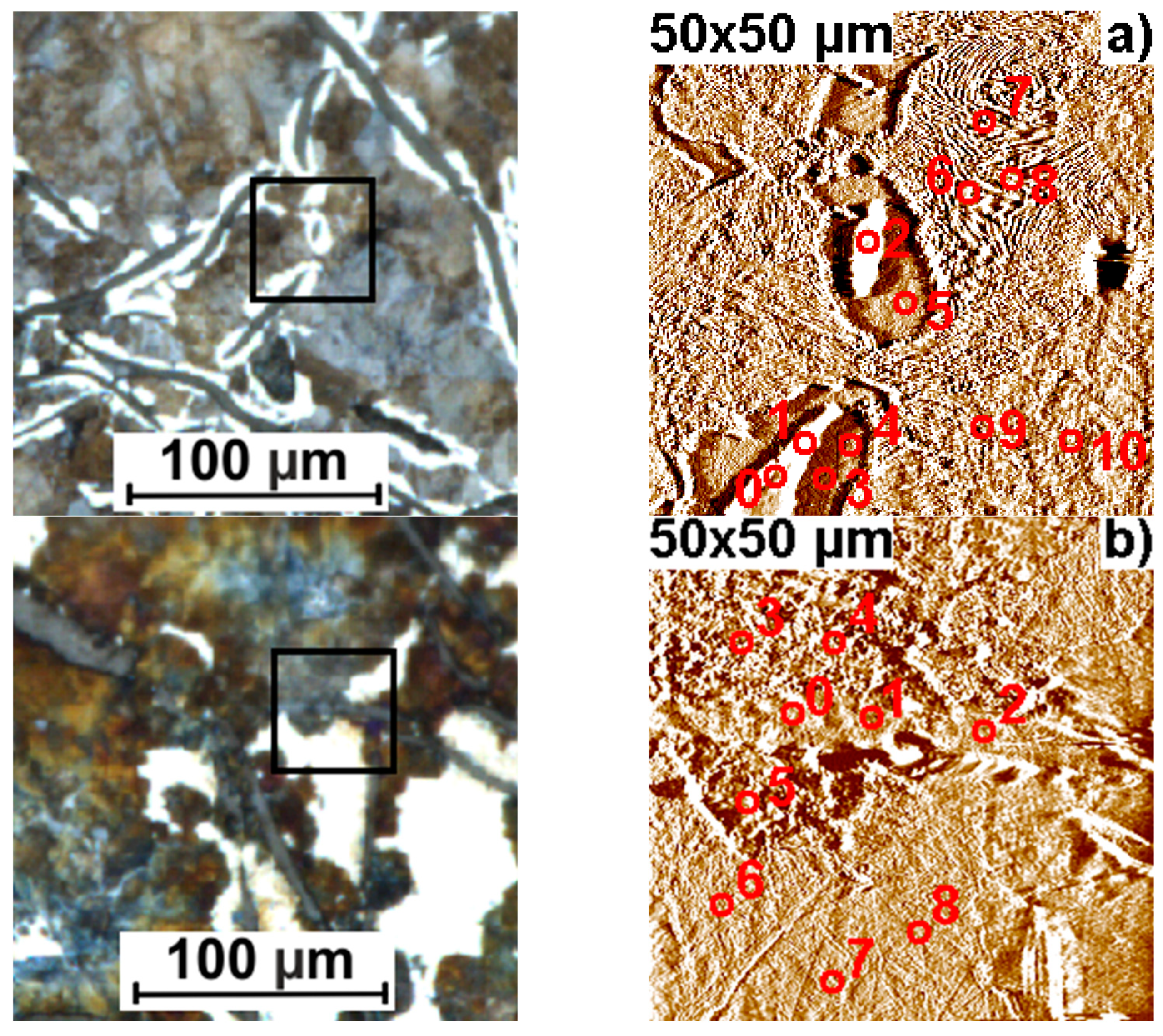
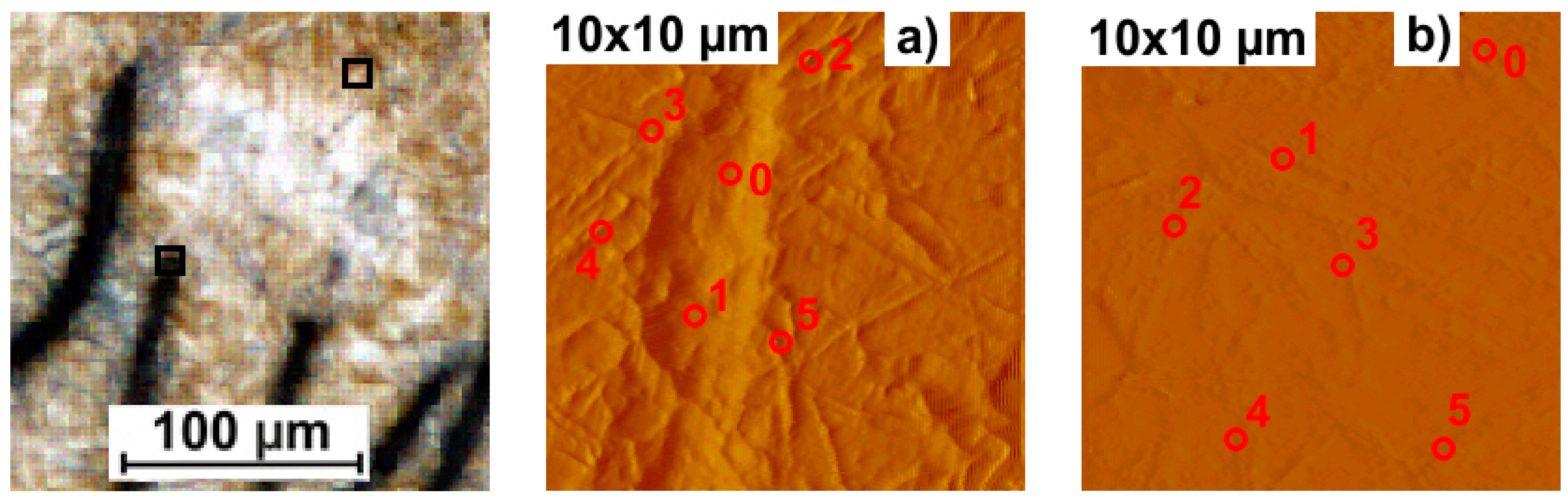
3.2. Nanoindentation Study of Selected Structure Components

The experimental samples subjected to different heat treatment conditions and then observed by light optical microscopy (LOM) were subsequently tested using quasistatic nanoindentation to confirm the presence of the structural components. Figure 8a–c show the of observations of samples after the continuous cooling treatments. The left pictures in Figure 8a–c show the investigated area observed by LOM with specific analysis locations indicated by a black square, where the right picture is the SPM scan of this location. The sample surfaces at these chosen locations were scanned by scanning probe microscopy (SPM). The scanned images were made by indenting tip oscillation with a specific frequency over the surface, while scanning the selected area without causing any physical changes to the surface.
The mapping of the microstructural components in all investigated cases of heat or mechanical–heat treatment was carried out based on the resulting values of the local mechanical properties and using visual information from the LOM (Figure 6 and Figure 7) and SPM indentation scans.
The microstructure of the matrix and the structural constituents present in it varied according to the applied heat treatment, and the nanoindentation results confirmed the presence of the estimated phases in all the investigated cases of the continuously cooled samples. At cooling by 1 °C s−1 (Figure 8a), there was a pearlite matrix (P; H = 4.17 ± 0.43 GPa; Er = 206.39 ± 14.49 GPa) with small areas of white ferrite (F; H = 2.71 ± 0.13 GPa; Er = 157.74 ± 6.29 GPa) around the lamellae (Table 4). This microstructure corresponds to very slow cooling in the equilibrium state. The presence of ferrite areas indicates even slower cooling than in treatment of the as-delivered state. Moreover, the presence of graphite lamellae surrounded by ferritic halos plays an important role not only in the mechanical properties but also in the vibration-damping capacity of the material. Cao et al. [30] demonstrated that the damping performance of cast iron is closely linked to the graphite morphology, content, and the distribution of phases in the matrix. A higher number of phase interfaces enhances interfacial slip and friction, leading to improved damping behavior. Therefore, preserving the graphite structure and optimizing the surrounding matrix composition can contribute to maintaining both the mechanical stability and the functional damping properties of grey cast iron.
In the case of the 10 °C s−1 continuous cooling rate (Figure 8b), dark pearlite areas (P; H = 3.68 ± 0.05 GPa; Er = 193.36 ± 4.68 GPa) were observed together with light areas of bainite (B; H = 5.99 ± 0.45 GPa; Er = 224.85 ± 7.60 GPa). The white area appears compact in the preview image, but the LOM analysis with significantly higher resolution revealed the presence of needle particles in the area (Figure 6b). The high value of the nanohardness in location b8 indicates the possible presence of martensite (M; H = 7.22 GPa; Er = 222.46 GPa) (Table 5).
The matrix in the last case of continuous quenching at a rate of 100 °C s−1 (Figure 8c) was fully martensitic (M; H = 9.82 ± 0.84 GPa; Er = 172.94 ± 8.79 GPa) with clearly visible needles (Table 6). The high nanohardness indicates that it is fresh martensite after rapid cooling. The small sample used and also fixed in the clamps of the dilatometer during the experiment did not show the negative effects of internal stresses caused by such rapid cooling. However, high internal stresses up to cracks can be expected in the real heat treatment of a larger component.
Figure 9 shows the LOM and SPM scan for the austempered sample, which includes a specific tempering holding period. In this case, two SPM scans were carried out. The first was the area at the boundary of the lamella, where the needle network was densest (a). A second scan was chosen in the matrix at a location significantly distant from the graphitic lamellae (b).
The hardness values and reduced Young’s modulus of the needle-like structure located mostly at the lamella’s boundaries (Table 7) confirm that the structure is ausferrite (AF, H = 2.62 ± 0.24 GPa; Er = 82.09 ± 2.73 GPa). Several authors [11,31,32] present such results in a case of similar austempering heat treatment of cast irons. The nanoindentation analysis of the matrix shows the presence of martensite and some ausferrite too (Table 8). The nanohardness of this martensite (M, H = 7.83 ± 0.88 GPa; Er = 153.61 ± 19.26 GPa) was lower than the fresh martensite by continuous cooling at 100 °C s−1. The local mechanical properties of ausferrite (AF, H = 3.20 ± 0.24 GPa; Er = 93.57 ± 1.88 GPa) were similar to the values measured near the lamellae.
The last case of treatment (Figure 10) is ausforming, which includes the application of controlled deformation. The selection of measurement locations followed the same principle as for austempering. The increased occurrence of ausferrite (AF, H = 2.82 ± 0.19 GPa; Er = 91.46 ± 7.07 GPa) was also shown at the boundary of the graphite lamella (Table 9). However, the matrix showed more martensite presence compared to the austempered sample (Table 10). The applied deformation accelerates the nucleation rate during the isothermal transformation, and the C-enriched austenite leads to a greater amount of martensitic structure (M, H = 7.65 ± 0.45 GPa; Er = 147.60 ± 3.75 GPa), resulting in an increase in the general hardness HB of this sample compared to the austempering sample.

4. Conclusions

The study focused on the influence of selected heat treatments on the microstructure and local mechanical properties of EN-GJL-300 grey cast iron in terms of increasing its hardness and durability. The presented research offers the following conclusions:
  • The local mechanical properties of graphite lamellae were almost unchanged in all heat treatment cases, with average values of H = 0.65 ± 0.12 GPa and Er = 32.8 ± 4.55 GPa. The shape, size, and morphology of the lamellae did not change significantly, which is important for maintaining the damping properties of the material.
  • The three investigated continuous cooling rates confirmed the expected phase transformations in the matrix. Cooling at a rate of 100 °C s−1 appears to be unsuitable due to high internal stresses and the risk of cracking. At a rate of 1 °C s−1, ferritic regions around the graphite lamellae were formed in the microstructure, while the surface hardness (247 HB) was lower than in the as-delivered state (277 HB). The most advantageous was the cooling rate of 10 °C s−1, which led to the formation of a bainitic matrix with a small proportion of martensite and a significant increase in hardness to 415 HB. The measured nanomechanical properties corresponded to the phases—bainite (H = 5.99 ± 0.45 GPa; Er = 224.85 ± 7.60 GPa) and martensite (H = 7.22 GPa; Er = 222.46 GPa).
  • After austempering and ausforming, an acicular microstructure appeared in the structure, especially around the graphite lamellae. Local mechanical properties of these areas confirmed the presence of ausferite—after austempering (H = 3.20 ± 0.24 GPa; Er = 93.57 ± 1.88 GPa) and after ausforming (H = 2.82 ± 0.19 GPa; Er = 91.46 ± 7.07 GPa). The matrix after austempering contained martensite (H = 7.83 ± 0.88 GPa; Er = 153.61 ± 19.26 GPa) and some ausferite, while after ausforming it was mainly composed of martensite (H = 7.65 ± 0.45 GPa; Er = 147.60 ± 3.75 GPa), the increased proportion of which was a consequence of the applied deformation. The measured values of the general hardness (HBAT = 331; HBAF = 376 ± 9) correspond to the local properties of the matrix.
  • The austempering and ausforming heat treatments resulted in a fine-grained microstructure, but the hardness achieved was lower than with continuous cooling at a rate of 10 °C s−1. Therefore, this regime appears to be the most suitable from the point of view of optimizing wear resistance. A disadvantage of ausforming is its limited applicability to parts with complex shapes.
The presented research will be used to further investigation of the wear and tribological properties of EN-GJL-300 after heat treatment. Heat treatment will not be applied to the entire volume to preserve the damping properties of the product but just to specific subsurface layers by applying one of the progressive methods of case hardening, which will be another area of interest for future research.

Author Contributions

Conceptualization, P.P. and I.B.; methodology, J.M.; software, M.K. (Michal Krbata); validation, M.K. (Marcel Kohutiar), M.B. and M.K. (Michal Krbata); formal analysis, P.P. and I.K.; investigation, I.B.; resources, J.M. and M.K. (Marcel Kohutiar); writing—original draft preparation, I.B. and M.K. (Michal Krbata); writing—review and editing, M.K. (Michal Krbata); visualization, M.B. and I.K.; supervision, P.P. and I.K.; project administration, I.B. and M.K. (Marcel Kohutiar); funding acquisition, J.M. and M.B. All authors have read and agreed to the published version of the manuscript.

Funding

This work was supported by the Slovak Research and Development Agency under the Contract no. SK-PL-23-0018.

Data Availability Statement

The original contributions presented in this study are included in the article. Further inquiries can be directed to the corresponding author.

Conflicts of Interest

The authors declare no conflicts of interest.

References

  1. Shivarudrappa, P.K. Changes in Gray Cast Iron over the Last Century—An Initial Study. Master‘s Thesis, Lund University, Lund, Sweden, 2021. [Google Scholar]
  2. Ujjal, T.; Paul, D.; Mehtani, H.K.; Bhagavath, S.; Alankar, A.; Mohapatra, G.; Sahay, S.S.; Panwar, A.S.; Karagadde, S.; Samajdar, I. The Origin of Graphite Morphology in Cast Iron. Acta Mater. 2022, 226, 117660. [Google Scholar] [CrossRef]
  3. Eperješi, Š.; Matvija, M.; Bartošová, D.; Fecko, D.; Pribulová, A. Effect of Heat Treatment Conditions on Microstructure of Cast Iron. Manuf. Technol. 2017, 17, 29–33. [Google Scholar]
  4. Xing, J.; Wang, Q.; Chang, J. Microstructure of Martensite/Bainite Dual-Phase Grey Cast Iron and Its Strengthening Mechanism. ISIJ Int. 2007, 47, 1776–1780. [Google Scholar] [CrossRef]
  5. Kovacs, B.V.; Keough, J.R. Physical Properties and Application of Austempered Gray Iron. AFS Trans. 1993, 101, 283–291. [Google Scholar]
  6. Wang, B.; Pan, Y.; Liu, Y.; Lyu, N.; Barber, G.C.; Wang, R.; Hu, M. Effects of quench-tempering and laser hardening treatment on wear resistance of gray cast iron. J. Mater. Res. Technol. 2020, 9, 8163–8171. [Google Scholar] [CrossRef]
  7. Sarkar, T.; Bose, P.K.; Sutradhar, G. Effect of the Time and Temperature of Isothermal Quenching on Microstructure and Mechanical Properties of Bainitic Gray Cast Iron. Met. Sci. Heat Treat. 2020, 61, 552–558. [Google Scholar] [CrossRef]
  8. Hsu, C.H.; Shy, Y.H.; Yu, Y.H.; Lee, S.C. Effect of Austempering Heat Treatment on Fracture Toughness of Copper-Alloyed Gray Iron. Mater. Chem. Phys. 2000, 63, 75–81. [Google Scholar] [CrossRef]
  9. Navarro-Mesa, C.H.; Gomez-Botero, M.; Montoya-Mejía, M.; Ríos-Diez, O.; Aristizabal-Sierra, R. Wear Resistance of Austempered Grey Iron under Dry and Wet Conditions. J. Mater. Res. Technol. 2022, 21, 4174–4183. [Google Scholar] [CrossRef]
  10. Wang, B.; Han, X.; Barber, G.C.; Pan, Y. Wear Behavior of Austempered and Quenched and Tempered Gray Cast Irons under Similar Hardness. Metals 2019, 9, 1329. [Google Scholar] [CrossRef]
  11. Hu, H.; Xu, G.; Dai, F.; Tian, J.; Chen, G. Critical Ausforming Temperature to Promote Isothermal Bainitic Transformation in Prior-Deformed Austenite. Mater. Sci. Technol. 2019, 35, 420–428. [Google Scholar] [CrossRef]
  12. Chiou, C.S.; Yang, J.R.; Huang, C.Y. The Effect of Prior Compressive Deformation of Austenite on the Toughness Property in an Ultra-Low Carbon Bainite Steel. Mater. Chem. Phys. 2001, 69, 113–124. [Google Scholar] [CrossRef]
  13. Lee, C.H.; Bhadeshia, H.K.D.H.; Lee, H.C. Effect of Plastic Deformation on the Formation of Acicular Ferrite. Mater. Sci. Eng. A 2003, 360, 249–257. [Google Scholar] [CrossRef]
  14. Agnani, M.; Findley, K.O. Effects of Retained Austenite and Martensite Microstructure on Fatigue Crack Propagation in Quenched and Tempered High Carbon Steels. Int. J. Fatigue 2024, 188, 108529. [Google Scholar] [CrossRef]
  15. Fernández-Valdivielso, A.; López de Lacalle, L.N.; Fernández-Lucio, P.; González, H. Turning of austempered ductile iron with ceramic tools. Proc. Inst. Mech. Eng. Part B J. Eng. Manuf. 2021, 235, 484–493. [Google Scholar] [CrossRef]
  16. Balachandran, G.; Aravind, V.; Kamaraj, M.; Ekusa, K. Mechanical and Wear Behavior of Alloyed Gray Cast Iron in the Quenched and Tempered and Austempered Conditions. Mater. Des. 2011, 32, 4042–4049. [Google Scholar] [CrossRef]
  17. Akinribide, O.J.; Akinwamide, S.O.; Obadele, B.A.; Ogundare, O.D.; Ayeleru, O.O.; Olubambi, P.A. Tribological Behaviour of Ductile and Austempered Grey Cast Iron under Dry Environment. Mater. Today Proc. 2021, 38 Pt 2, 1174–1182. [Google Scholar] [CrossRef]
  18. Teng, X.Y.; Pang, J.C.; Liu, F.; Zou, C.L.; Gao, C.; Li, S.X.; Zhang, Z.F. Fatigue Strength Optimization of Gray Cast Iron Processed by Different Austempering Temperatures. Int. J. Fatigue 2023, 175, 107831. [Google Scholar] [CrossRef]
  19. Feldshtein, E.; Devojno, O.; Wojciechowski, S.; Kardapolava, M.; Kasiakova, I. On the Microstructure, Microhardnessand Wear Behavior of Gray Cast Iron Surface Layer after Laser Strengthening. Materials 2022, 15, 1075. [Google Scholar] [CrossRef]
  20. ISO 6892-1:2016; Metallic Materials—Tensile Testing—Part 1: Method of Test at Room Temperature. International Organization for Standardization: Geneva, Switzerland, 2016.
  21. Barényi, I.; Majerík, J.; Bezecný, J.; Krbaťa, M.; Sedlák, J.; Jaroš, A. Material and Technological Aspects while Processing of Selected Ultra High Strength Steel. Manuf. Technol. 2019, 19, 184–189. [Google Scholar] [CrossRef]
  22. Cíger, R.; Barényi, I.; Krbaťa, M. Analysis of heat treatment parameters on the properties of selected tool steels M390 and M398 produced with powder metallurgy. Manuf. Technol. 2021, 21, 774–780. [Google Scholar] [CrossRef]
  23. ISO 6506-1; Metallic Materials-Brinell Hardness Test—Test Method. 3rd Edition. International Organization for Standardization (ISO): Geneva, Switzerland, 2014.
  24. Escherová, J.; Majerík, J.; Barényi, I.; Kohutiar, M.; Chochlíková, H. Experimental research and evaluation of mechanical properties of microstructural of high-components strenght steels by quasistatic nanoindentation. Eng. Rev. 2024, 44, 1–10. [Google Scholar] [CrossRef]
  25. Barényi, I.; Majerík, J.; Pokorný, Z.; Sedlák, J.; Bezecný, J.; Dobrocký, D.; Jaroš, A.; Eckert, M.; Jambor, J.; Kusenda, R. Material and Technological Investigation of Machined Surfaces of the OCHN3MFA Steel. Kov. Mater./Met. Mater. 2019, 57, 131–142. [Google Scholar]
  26. Fischer-Cripps, A.C. Nanoindentation; Springer: Berlin/Heidelberg, Germany, 2011. [Google Scholar]
  27. Kozłowska, A. Dilatometric Study on Phase Transformations in Non-Deformed and Plastically Deformed Medium-Mn Multiphase Steels with Increased Al and Si Additions. J. Therm. Anal. Calorim. 2025, 150, 1051–1058. [Google Scholar] [CrossRef]
  28. Zheng, J.; Li, J.; Li, S.; Tu, X.; Li, R. Effect of Salt Bath Temperature on Microstructure and Mechanical Properties of an Austempered Alloyed Cast Iron. China Foundry 2024, 21, 709–716. [Google Scholar] [CrossRef]
  29. Kaboli, K.; Mostafapour, M.; Kheirkhahan, N.; Edalati, E.; Solbi, E.; Babakhani, A.; Kiani-Rashid, A.R. Revisiting the Effect of Casting Thickness and Austempering Temperature of Gray Iron. J. Mater. Eng. Perform. 2024, 33. [Google Scholar] [CrossRef]
  30. Cao, X.; Zhang, Q.; Yu, J.; Yu, X. Effect of Compositional Changes and Heat Treatment on Microstructure and Mechanical Properties of Gray Cast Iron. J. Mater. Res. Technol. 2025, 35, 5336–5352. [Google Scholar] [CrossRef]
  31. Pereira, L.N.D.G.; Medeiros, R.G.D.C.; Freitas, P.G.M.D.; Silva, C.F.D.; Silva, L.M.D.; Leal, R.H. Microstructural Evaluation of an Austempered Cast Iron Alloy. Mater. Res. 2022, 25, e20210256. [Google Scholar] [CrossRef]
  32. Seikh, A.H.; Sarkar, A.; Singh, J.K.; Mohammed, S.M.A.K.; Alharthi, N.; Ghosh, M. Corrosion Characteristics of Copper-Added Austempered Gray Cast Iron (AGCI). Materials 2019, 12, 503. [Google Scholar] [CrossRef]
Figure 1. Microstructure of EN-GJL-300 in as-delivered state.
Metals 15 00530 g001
Figure 2. Shape and dimensions of the experimental sample [22].
Metals 15 00530 g002
Figure 3. Thermal regimes used for heat treating the samples.
Metals 15 00530 g003
Figure 4. Thermal regime used for heat treating the sample by austempering.
Metals 15 00530 g004
Figure 5. Thermal regime used for heat treating the sample by ausforming.
Metals 15 00530 g005
Figure 6. Evolution of microstructure in relation to the quenching (a) 1 °C s−1, (b) 10 °C s−1, and (c) 100 °C s−1.
Metals 15 00530 g006
Figure 7. Microstructure of the samples after (a) austempering and (b) ausforming.
Metals 15 00530 g007
Figure 8. In situ SPM scans of measured surfaces of continuous cooling samples with indentation locations: (a) 1 °C s−1, (b) 10 °C s−1, (c) 100 °C s−1.
Metals 15 00530 g008aMetals 15 00530 g008b
Figure 9. In situ SPM scans of measured surfaces with indentation locations of samples after austempering: (a) graphite lamellae adjacent area, (b) matrix.
Metals 15 00530 g009
Figure 10. In situ SPM scans of measured surfaces with indentation locations of samples after ausforming: (a) graphite lamellae adjacent area, (b) matrix.
Metals 15 00530 g010
Table 1. Chemical composition of experimental cast iron EN-GJL-300 (wt. %).
CSiMnSPFe
3.112.320.620.060.17Balance
Table 2. Basic mechanical properties of experimental cast iron EN-GJL-300.
Tensile Strength
Rm [MPa]
Yield Point
Rp0.2% [MPa]
Toughness at 20 °C [J·cm−2]Hardness [HB]Elongation
A5 [%]
2272158.52772.2
Table 3. Course of hardness HB in relation to the cooling rate.
Cooling Rate [°C s−1]110100AustemperingAusforming
Hardness HB247 ± 8415 ± 9534 ± 10331 ± 8360 ± 8
Table 4. Local mechanical properties of microstructure constituents for cooling rate (a) 1 °C s−1.
Locationa0a1a2a3a4a5a6a7a8a9a10
H [GPa]0.920.591.082.572.682.884.054.264.273.464.80
E r  [GPa]28.5231.0637.25150.91156.27166.04203.22225.72197.03186.32219.67
Phase/Structure constituentGGGFFFPPPPP
Table 5. Local mechanical properties of microstructure constituents for cooling rate (b) 10 °C s−1.
Locationb0b1b2b3b4b5b6b7b8
H [GPa]0.710.630.773.673.743.625.546.437.22
E r  [GPa]31.6633.5127.65187.40193.84198.83217.25232.44222.46
Phase/Structure
constituent
GGGPPPBBM
Table 6. Local mechanical properties of microstructure constituents for cooling rate (c) 100 °C s−1.
Locationc0c1c2c3c4c5
H [GPa]0.650.660.458.6610.6210.19
E r  [GPa]36.2535.7529.55171.29184.44163.10
Phase/Structure constituentGGGMMM
Table 7. Local mechanical properties of microstructure constituents for austempering—graphite lamellae adjacent area.
Locationa0a1a2a3a4a5
H [GPa]0.480.492.772.522.292.91
E r  [GPa]39.5140.8584.7778.6284.9780.01
Phase/Structure constituentGGAFAFAFAF
Table 8. Local mechanical properties of matrix microstructure constituents for austempering.
Locationb0b1b2b3b4b5
H [GPa]9.347.177.307.492.963.43
E r  [GPa]142.73186.92143.93140.8695.4591.69
Phase/Structure constituentMMMMAFAF
Table 9. Local mechanical properties of microstructure constituents for ausforming—graphite lamellae adjacent area.
Locationa0a1a2a3a4a5
H [GPa]0.630.482.822.522.903.04
E r  [GPa]26.3328.6597.8484.9283.9099.16
Phase/Structure constituentGGAFAFAFAF
Table 10. Local mechanical properties of matrix microstructure constituents for ausforming.
Locationb0b1b2b3b4b5
H [GPa]8.287.057.837.308.197.27
E r  [GPa]153.04143.61143.36150.09150.45145.06
Phase/Structure constituentMMMMMM
Disclaimer/Publisher’s Note: The statements, opinions and data contained in all publications are solely those of the individual author(s) and contributor(s) and not of MDPI and/or the editor(s). MDPI and/or the editor(s) disclaim responsibility for any injury to people or property resulting from any ideas, methods, instructions or products referred to in the content.

