Article

Study of Electrochemical Migration Behavior of Sn1.0Ag Solder

School of Materials Science and Engineering, Dalian University of Technology, Dalian 116024, China
*
Author to whom correspondence should be addressed.
Metals 2025, 15(4), 434; https://doi.org/10.3390/met15040434
Submission received: 10 March 2025 / Revised: 9 April 2025 / Accepted: 10 April 2025 / Published: 12 April 2025
(This article belongs to the Special Issue Advances in Welding and Joining of Alloys and Steel)

Abstract

With the enhancement of environmental protection awareness and the implementation of related regulations, lead-free soldering materials are gradually replacing the traditional leaded soldering materials in the field of electronics manufacturing. Sn–Ag soldering materials have become a research hotspot because of their good mechanical properties, solderability, and thermal fatigue reliability, but their high cost limits their large-scale application. The low silver content of the Sn–Ag solder reduces the cost while maintaining an excellent performance. However, as the size of electronic components shrinks and the package density increases, the solder joint spacing decreases, the potential gradient increases, and electrochemical migration (ECM) becomes a key factor affecting the reliability of solder joints. In this study, the ECM failure process was simulated by the water droplet method, and the SEM and XPS analyses were utilized to investigate the ECM mechanism of Sn1.0Ag solder alloys, and the effects of different concentrations of NaCl solutions on their ECM were investigated. The results showed that the ECM of the Sn1.0Ag solder occurred in a 0.01 M NaCl solution, the dendritic composition was pure Sn, and the white precipitate was a mixture of Sn(OH)2 and Sn(OH)4. With the increase in the NaCl concentration, the corrosion resistance of the Sn1.0Ag solder alloy decreases and the ECM reaction intensifies, but with a high concentration of the NaCl solution, a large amount of precipitation hinders the migration of Sn ions, resulting in the generation of no dendrites. The present study provides new insights into the ECM behavior of a low-silver-content Sn–Ag solder system.

1. Introduction

The traditional lead-containing solder has long dominated electronic assemblies by virtue of its good wettability, moderate melting point, and low cost. However, Pb is a heavy metal that is extremely harmful to the human body and the environment. With the increasing awareness of environmental protection and the implementation of related regulations (e.g., the EU RoHS directive), Pb-free soldering materials are gradually replacing the traditional Pb-containing soldering materials in the field of electronics manufacturing [1,2]. The Sn–Ag alloy has better toughness and plasticity and wettability which results in good welding reliability, and the mechanical properties of its welded joints, such as shear resistance, tensile strength, and fatigue resistance, are better than the Sn–Pb alloy [3].
Sn–Ag solder is an important lead-free solder material, the material of choice for high-end electronics manufacturing and high-temperature applications, and is commonly used in aerospace electronics, military equipment, and medical devices where solder joint reliability is critical. In the civilian fields of automotive electronics engine control unit (ECU) and power modules (such as IGBT) welding, photovoltaic industry solar panels interconnection welding, high-power LED heat dissipation substrate welding. Moreover, Sn-Ag alloy is often used as an interconnect solder for millimeter-wave device soldering in 5G base stations, where high signal integrity is required. [4,5]. But their large-scale application has been hindered by the high cost of Ag. The low silver content of Sn–Ag lead-free solders has been a research hotspot, and the lower Ag content not only reduces the production cost, but also maintains the advantages of the good mechanical properties, good solderability, and high thermal fatigue reliability of Sn–Ag solder [6].
With the continuous development of chip technology, the size of electronic components is constantly shrinking, and the package density is getting higher and higher, which makes the spacing between solder joints become smaller and the potential gradient higher, which makes them highly susceptible to ECM-induced insulation failures between wires [7,8,9]. Failure due to electrochemical migration (ECM) is one of the key factors affecting the reliability of component solder joints. ECM is a common failure phenomenon in electronic devices that occurs mainly between two metal electrodes [10,11]. It refers to the migration of metal ions from the anode to the cathode through an electrolyte medium (usually a water film or a thin electrolyte layer) under the action of a DC electric field and the deposition of conductive dendrites or filaments on the cathode surface [12]. These conductive deposits may ultimately lead to short circuits, thereby affecting the reliability and service life of the equipment. In recent years, there has been a lot of interest in studying the factors affecting the ECM process in solder alloys. The voltage, spacing, concentration, and pH of the electrolyte solution all have an effect on the ECM process [13,14,15,16].
The water droplet method has become the main method to study ECM because of its advantages of an easy operation, intuitive results, and good reproducibility. This method can rapidly characterize the anti-migration properties of materials by simulating a humid environment, dropping an electrolyte solution on the surface of insulating materials, and directly observing the growth of dendrites after applying a direct current (DC) voltage. Although the water droplet method is an accelerated test, the cost of the experimental equipment is low, and it can effectively reflect the risk of the ion migration of materials in the actual humid and hot environments, so it has become an effective means of evaluating ECM.
The ECM of Sn [17,18,19] and Ag [20,21] has been studied, but there is still a lack of research on the electrochemical migration of Sn–Ag-based lead-free solders with a low silver content. In this study, the water droplet method was used to simulate the electrochemical migration failure process, and SEM and XPS analyses were applied to determine the electrochemical migration mechanism of Sn1.0Ag solder alloys. In addition, the effects of different concentrations of NaCl solutions on the electrochemical migration of Sn1.0Ag solder alloys were also investigated.

2. Materials and Methods

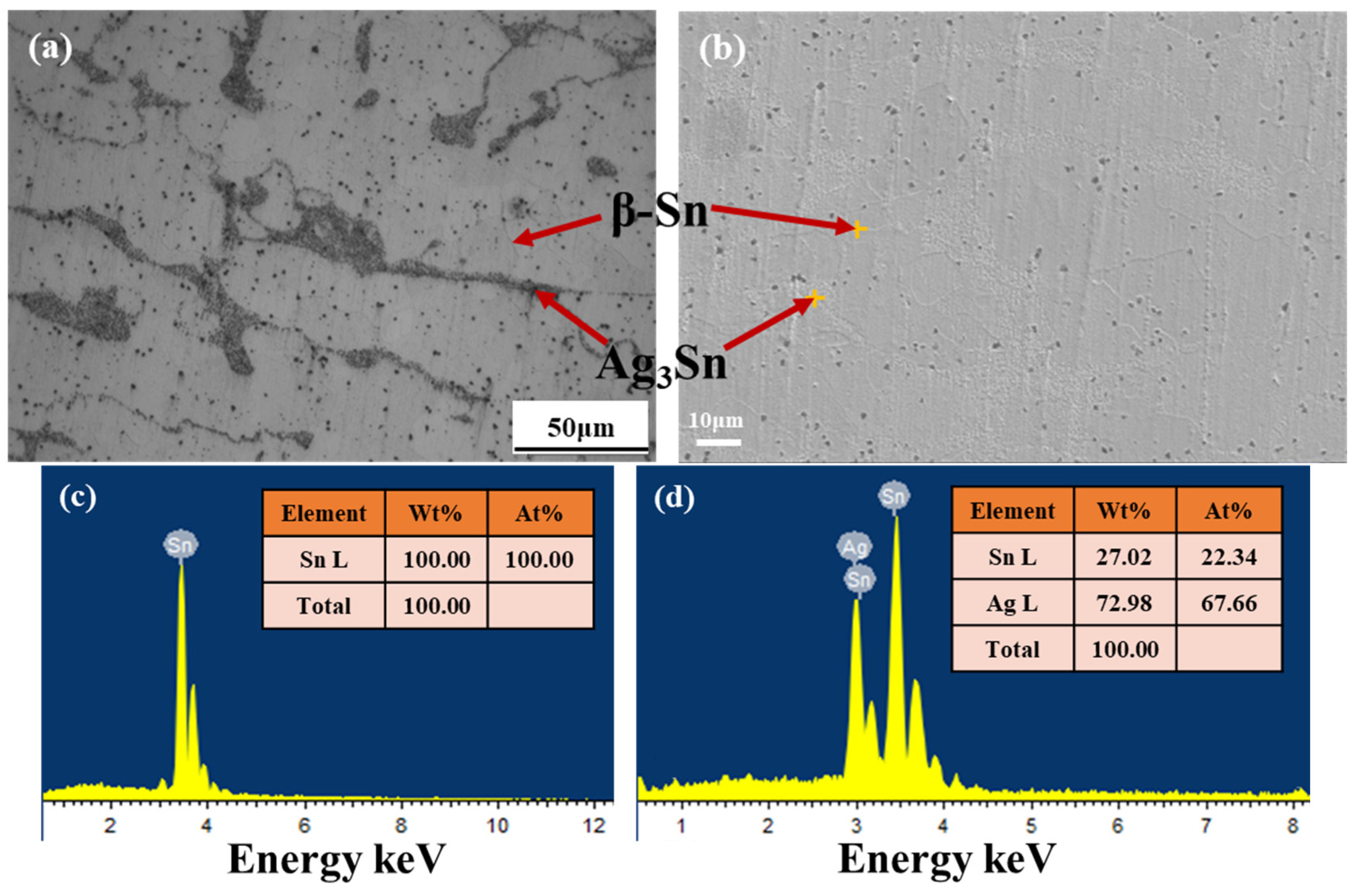
2.1. Sample Preparation

First, the Sn1.0Ag alloy block (Zhenjiang Pan-Asia-Tech Electronic Technology Co., Zhenjiang, China) was cut into sheets with dimensions of 10 × 3 × 0.3 mm3. Then, the cross-section of the solder alloy piece was sanded with 800–1200–2000 mesh silicon carbide hydroabrasive sandpaper to remove surface oxides, and the sanding ensured that the scratches were uniform and of the same depth. Subsequently, the polished alloy sheet was placed in acetone and ultrasonicated for 5 min to remove surface grease. Finally, it was removed, the surface was rinsed with deionized water, blown dry, and fixed on the resin substrate (Shanghai Weitao Rubber & Plastic Products Co., Shanghai, China) with the two electrodes 0.5 mm apart.
A thin slice of Sn1.0Ag alloy block with a size of 2 × 1 × 0.5 mm3 was cut. Its surface was gradually polished with 800–1200–1500–2000 mesh silicon carbide hydroabrasive sandpaper and polished with 0.05 μm Al2O3 suspension to a mirror-like surface and then ultrasonicated in acetone for 5 min, and the surface was blown clean. The prepared metallographic samples were etched in 2% HCl + 98% ethanol for 20 s [22], removed, the surface was rinsed with deionized water, blown dry, and the microstructure of the Sn1.0Ag alloy was characterized using optical microscopy and scanning electron microscopy.

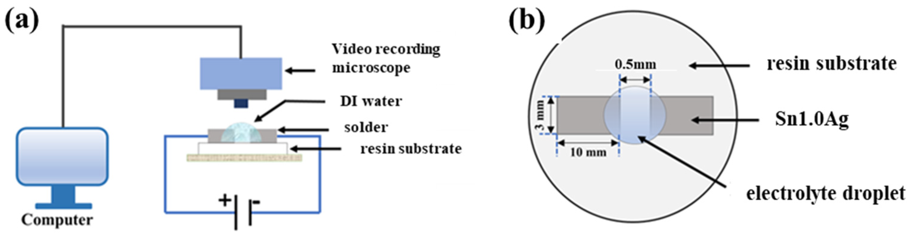
2.2. Experimental System Construction for Water Droplet Method

The water droplet experiment is an accelerated experiment that simulates a realistic solder joint after liquid attachment in a humid environment. As shown in Figure 1, the electrodes were connected to an electrochemical workstation (CS350M) and placed under a stereomicroscope (Olympus SZX12, Tokyo, Japan), and a drop of electrolyte solution with a volume of 5 μL was dropped between the two electrodes. The stereomicroscope was responsible for real-time observation of the growth of dendrites and precipitates between the two electrodes, and the electrochemical workstation was responsible for supplying a 1.5 V DC voltage and recording the change in current in the whole circuit over time.

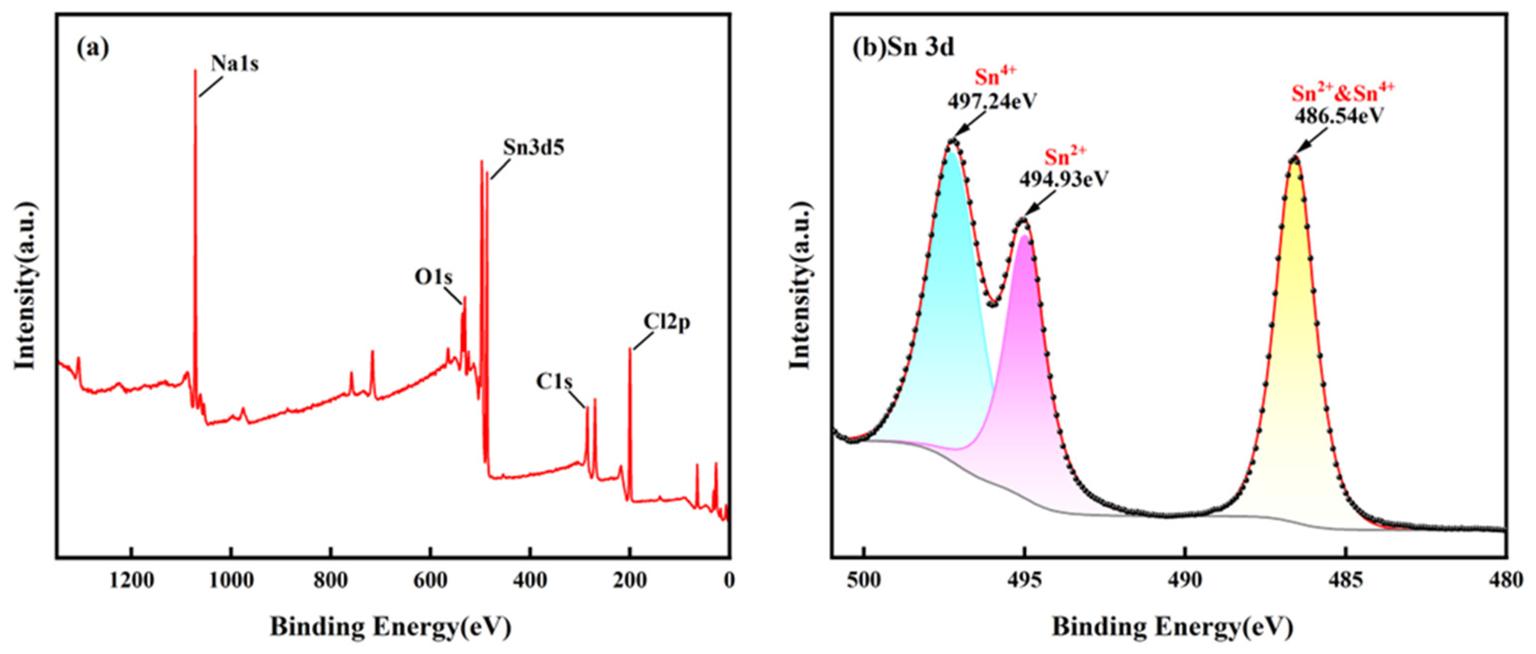
2.3. Analyzing ECM Generators

After the ECM experiment, the samples were dried at room temperature. After drying, the samples were gold-sprayed using a vacuum coater (Leica EM ACE 600, Leica Microsystems, Wetzlar, Germany), followed by characterization of the morphology of the electrochemical migration products using a scanning electron microscope [SEM, Zeiss supra 55 (Vp), Carl Zeiss AG, Oberkochen, Germany]. The precipitates were analyzed by XPS (ESCALAB 250Xi, Thermo Fisher Scientific, East Grinstead, United Kingdom), the spectra were measured with Al Ka (hv = 1486.6 eV) radiation, and the overall energy resolution was approximately 0.45 eV.

2.4. Polarization Test

To investigate the effect of NaCl concentration on the corrosion resistance of Sn1.0Ag solder, the polarization curves of Sn1.0Ag solder were measured using an electrochemical workstation (CS350M, Corrtest Instruments, Wuhan, China) and a three-electrode system (Sn1.0Ag solder at the anode, Pt at the cathode, and saturated mercuric glycol electrode at the reference electrode). The potential scanning range was from −1.0 V to 0.1 V, the scanning rate was 1 mV/s, and the electrolyte solution was NaCl solution (0.001 M, 0.01 M, and 0.6 M).

3. Results

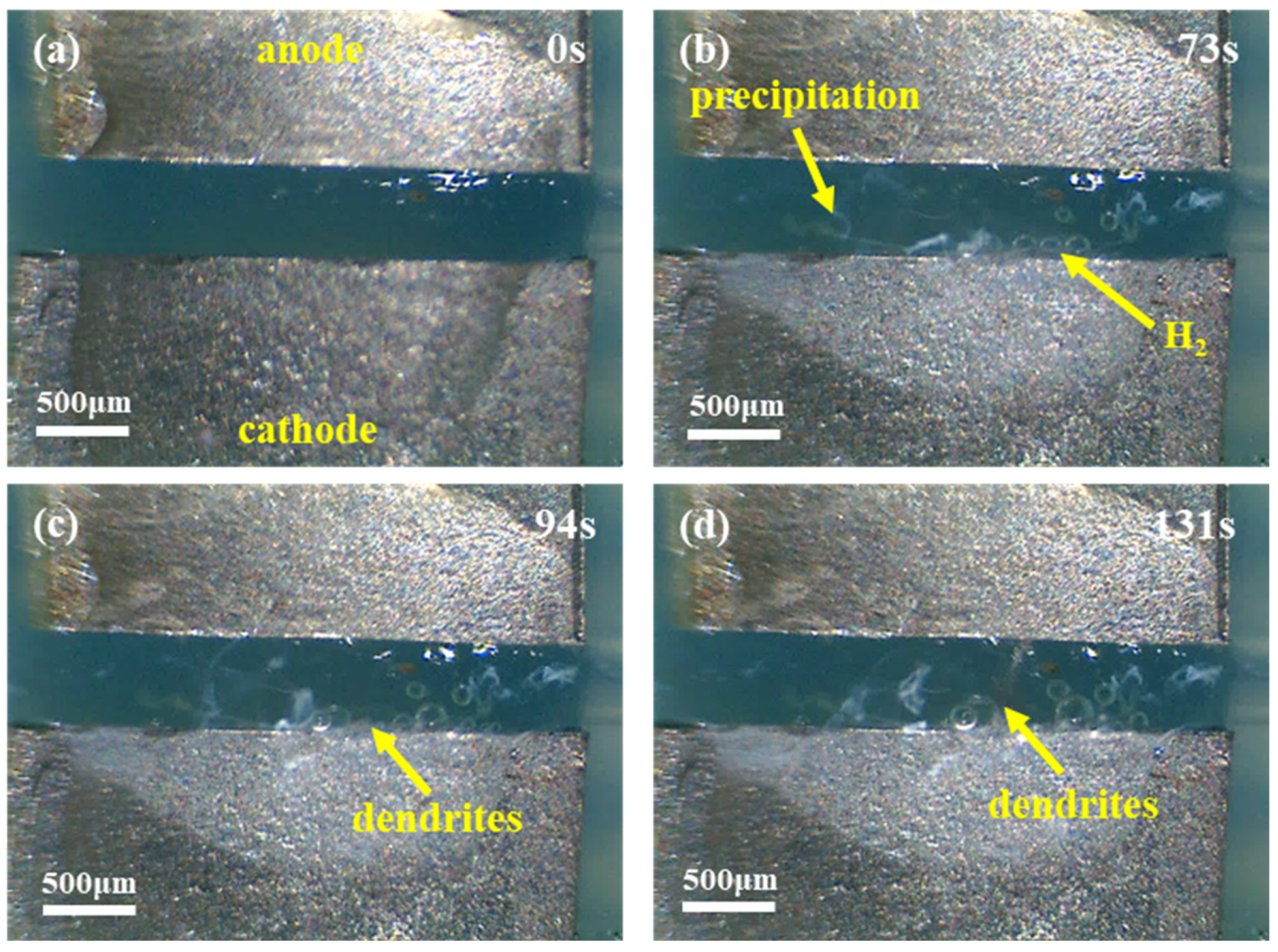
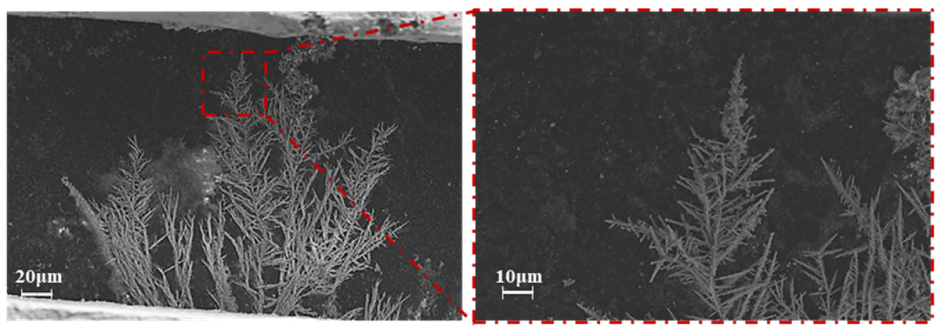
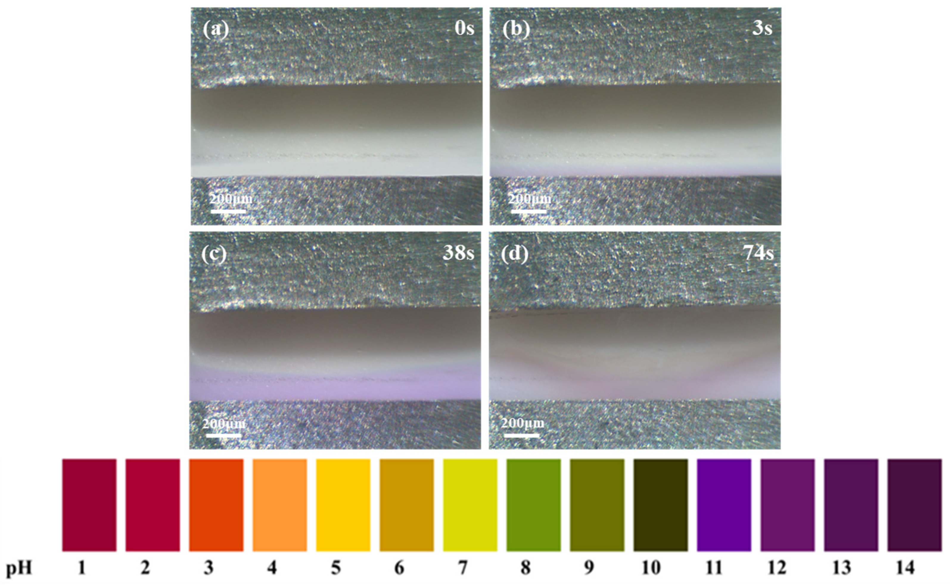
3.1. ECM of Sn1.0Ag Solder

Figure 2 shows the microstructure of the Sn1.0Ag solder alloy. It can be found that the Sn1.0Ag alloy consists of two phases, β-Sn and Ag3Sn. The granular Ag3Sn is diffusely distributed in the β-Sn collective, which gives the solder alloy an excellent plastic deformation capability.
Figure 3 shows the in situ observation of the ECM phenomenon occurring in the Sn1.0Ag solder in the de-energized 0.01 M NaCl droplet. Figure 3a shows the initial state without energization, with a spacing of 0.5 mm between the two Sn1.0Ag solder electrodes and a drop of 5 μL in volume with a concentration of 0.01 M of the NaCl solution in the middle. After being energized for a period of time (73 s), a small number of bubbles would be generated at the end face of the cathode, and a small amount of white precipitate would be generated in the middle of the two electrodes, as shown in Figure 3b. As the energization time continued, after about 94s, dendritic crystals precipitated at the cathode end face (Figure 3c) and grew toward the anode. Eventually, after 131 s, the dendritic crystals bridged the cathode and anode together to form a short circuit (Figure 3d).
Figure 4 shows the variation in the current in the circuit with time during the process. It can be seen that during the whole process of electrochemical migration, the current is very small and varies smoothly for a long period of time, and the moment the current surge occurs, it is the dendrite that connects the two electrodes and the circuit fails. Therefore, in this work, the time of the current surge is subsequently taken as the electrochemical migration failure time.

3.2. ECM Mechanism of Sn1.0Ag Solder

During ECM, the metal atoms at the anode lose electrons to ions in the solution under the action of the power source, move toward the cathode under the action of the electric field, and subsequently accept electrons at the cathode to reduce to atoms and grow toward the anode in the form of dendrites. Figure 5 shows the SEM image of the dendrites generated by the ECM of the Sn1.0Ag solder material. Through observation, it can be found that the dendrite growth sites are concentrated in part of the region, one with the most rapid growth, and the rest of the dendrites are “clustered” in the periphery, slowly growing toward the anode. All the dendrites consist of a main stem and many branches, and secondary branches are formed on the branches, and the growth rate of the branches is much smaller than that of the main stem. The EDS analysis of the dendrite composition was performed and the results are shown in Figure 6. From the EDS results, it can be seen that only Sn is contained in the dendritic elements, which means that only Sn participated in the reaction of the dendritic growth during the ECM process of the Sn1.0Ag solder alloy, and Ag continued to remain in the solder alloy in the form of Ag3Sn.
In order to determine the composition of the white precipitate produced during the ECM of the Sn1.0Ag solder, five drops of the pH indicator were added to a 0.01 M NaCl solution to observe the pH change during the ECM process. As shown in Figure 7a–d, at the very beginning the solution was light yellow in color and the pH was near 7. After applying the voltage, a lavender color was observed near the cathode, which indicated that the oxygen absorption and hydrogen precipitation reaction occurred at the cathode, generating a large amount of OH. And due to the hydrogen precipitation reaction, the bubble evacuation convection effect occurs at the surface of the cathode [23], the concentration of OH near the cathode increases, and the purple color area becomes larger and larger (Figure 7c). At the same time, the Sn in the anode loses electrons and turns into ions in the solution, moving toward the cathode under the action of the electric field. When Sn ions and OH ions meet between the two electrodes, a white precipitate is produced (Figure 7d).
Figure 8 shows a SEM image of the precipitate produced by the electrochemical migration of the Sn1.0Ag solder. From the Pourbaix plot of the Sn (Figure 9), it can be seen that the white precipitate produced by electrochemical migration may be a mixture of Sn(OH)2 and Sn(OH)4. The white precipitate was analyzed by XPS, and the results are shown in Figure 10. From Figure 10a, it can be seen that the precipitate contains mainly Sn and O elements, and Cl and Na are electrolyte solution elements. The XPS peak spectra of the known Sn species were checked [24,25]: SnO-486 eV and 494.4 eV and SnO2-486.6 eV and 495.7 eV. The results of Figure 10b show that the elemental Sn in the precipitate has three characteristic peaks, 486.54 eV, 494.93 eV, and 497.24 eV, which suggests that the precipitate is a mixture of SnO and SnO2.
It can be determined that the main reactions of the Sn1.0Ag solder alloy material in the occurrence of ECM are as follows [27,28,29]:
Anode:
S n 2 e S n 2 +
S n 2 + 2 e S n 4 +
Cathode:
2 H 2 O + 2 e H 2 + 2 O H
2 H 2 O + O 2 + 4 e 4 O H
S n 2 + + 2 e S n
S n 4 + + 4 e S n
Droplet:
S n 2 + + 2 O H S n ( O H ) 2
S n 2 + + 2 H 2 O S n ( O H ) 2 + 2 H 2 O + 2 H +
S n 4 + + 4 O H S n ( O H ) 4
S n 4 + + 4 H 2 O S n ( O H ) 4 + 4 H +
During the ECM of the Sn1.0Ag solder, the standard electrode potential of Sn is ESn = −0.1375 V (SHE), which is much smaller than the standard electrode potential of Ag (EAg = +0.7996 V (SHE) [23,30]), and Ag exists as Ag3Sn intermetallic compounds in the Sn1.0Ag solder, as shown in Figure 2. Ag3Sn is very stable, which results in Ag not being involved in ECM processes [31]. Only Sn in the anode loses electrons and becomes Sn2+ dissolved into the electrolyte solution (reaction 1). Part of the Sn2+ moves toward the cathode under the action of the electric field, while part of the Sn2+ will be further oxidized to Sn4+ at the anode (reaction 2). At the same time, hydrogen precipitation (reaction 3) and oxygen absorption (reaction 4) reactions occur at the cathode. Bubbles and a large amount of OH appear at the cathode end surface, and OH moves toward the anode under the action of the applied electric field. Under the continuous action of the applied electric field, Sn2+ and Sn4+ met with OH traveling in the opposite direction during their migration toward the cathode. At room temperature, the solubility products of Sn(OH)2 and Sn(OH)4 are Ksp (Sn(OH)2) = 5.45 × 10⁻²⁸) and Ksp (Sn(OH)4) = 10−56), respectively [32]. This indicates that both substances readily form precipitates at room temperature (Reactions (7)–(10)). The free states of Sn2+ and Sn4+ that do not participate in the reaction reach the cathode end face and are reduced to monomers, forming dendrites (Reactions (5) and (6)).

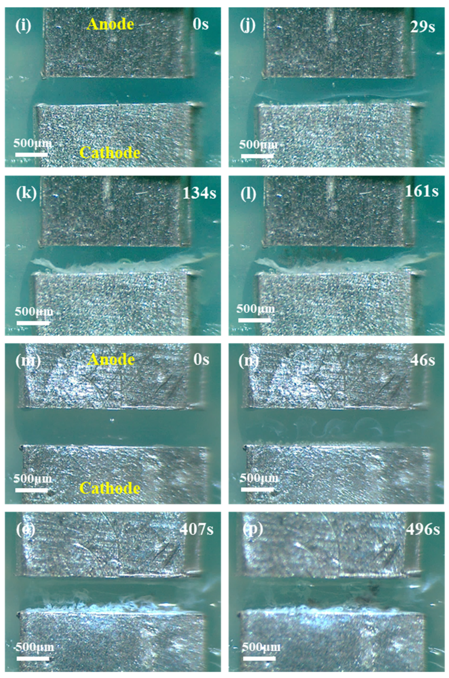
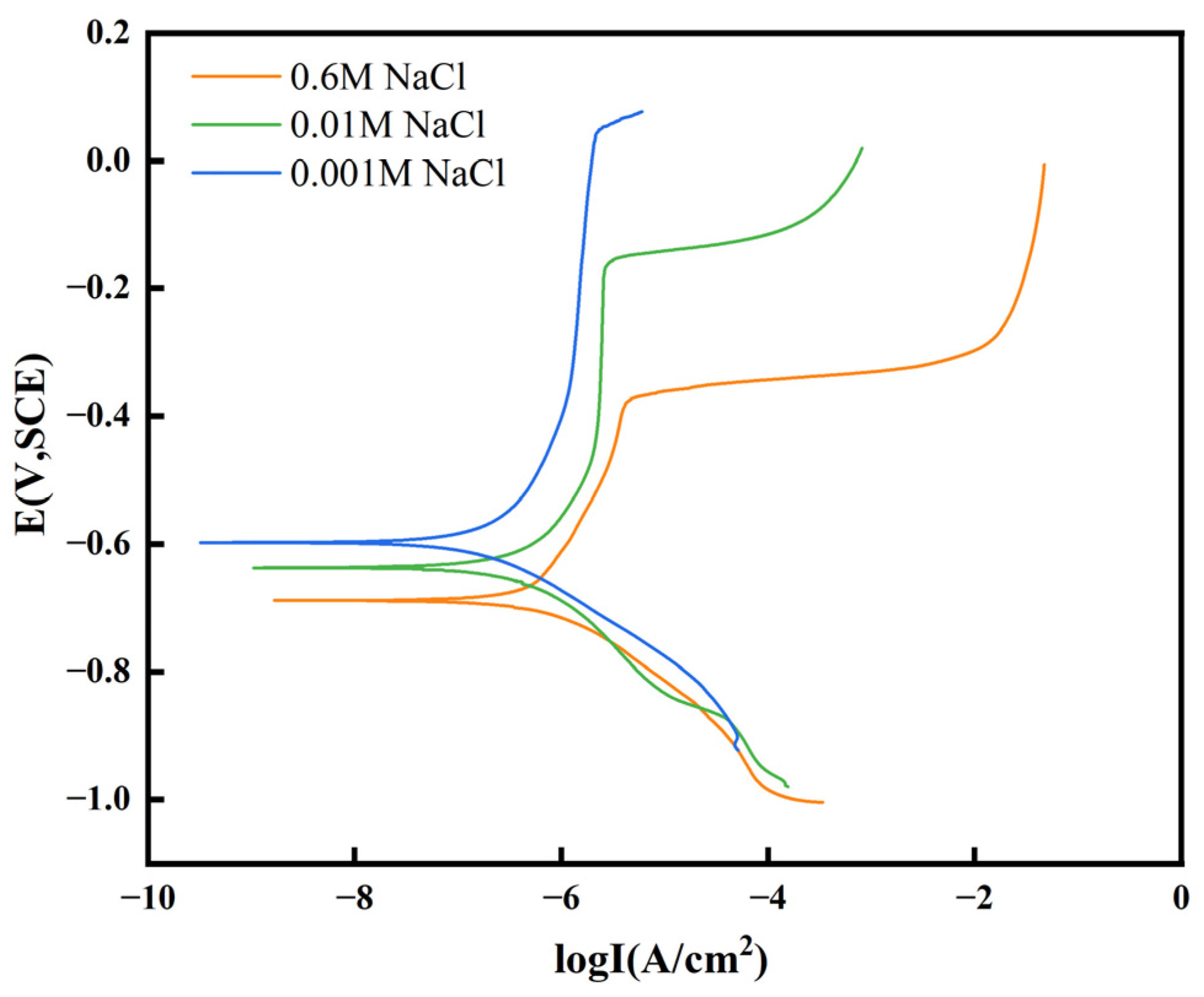
3.3. Effect of Different Concentrations of NaCl Solutions on ECM of Sn1.0Ag Solder

Electrochemical migration includes three important processes: anodic dissolution, ionic migration, and cathodic deposition [18,33]. The electrochemical migration behavior is mainly affected by the migration medium, electric field strength, and material composition. The droplet between two electrodes has a key role in electrochemical migration. Chloride ions are one of the most important contaminants in electronic devices and are very common in humid marine atmospheric environments as well as in flux residues [34].
In this paper, the electrochemical migration of the Sn1.0Ag solder was investigated in different concentrations of chloride ion solutions, high, medium, and low concentrations. The chloride ion concentration was 0.6 M in the high concentration solution (the mass fraction of the NaCl solution at this concentration is about 3.5%), 0.01 M in the medium concentration solution, and 0.001 M in the low concentration solution. Figure 11 demonstrates the effect of different chloride ion concentrations on the ECM of the Sn1.0Ag solder at 1.5 V. Overall, dendrites were generated in deionized water (0 M), low (0.001 M) and medium (0.01 M) NaCl droplets, while no dendrites grew in high (0.6 M) NaCl droplets. The amount of white precipitate during the process decreased with the decreasing NaCl concentration, and the extent of the bubble precipitation at the cathode also decreased with the decreasing NaCl concentration. The absence of dendrites in the 0.6 M NaCl droplet can be attributed to the fact that a large amount of the generated precipitate was deposited between the two electrodes, forming a barrier that impeded the movement of Sn ions toward the cathode. And with the high concentration droplet conductivity, the reaction at the cathode is intense and the OH generation rate is fast, and it is difficult to have free Sn ions deposited on the cathode end surface, so no dendrites were generated in the 0.6 M NaCl droplet.
In this study, the corrosion behavior of the Sn1.0Ag solder in 0.6 M NaCl, 0.01 M NaCl, and 0.001 M NaCl solutions was analyzed using polarization curves, as shown in Figure 12. The corrosion currents were determined by Tafel extrapolation. The corrosion parameters of Sn1.0Ag solder alloys at different concentrations are listed in Table 1. In the Sn1.0Ag solder in the 0.6 M NaCl solution the corrosion potential was −0.67 V, the corrosion current was 5.80 × 10⁻⁷ A/cm2, and the pitting potential was −0.38 V; in the 0.01 M NaCl solution the corrosion potential was −0.62 V, the corrosion current was 4.63 × 10⁻⁷ A/cm2, and the pitting potential was −0.16 V; in the 0.001 M NaCl solution the corrosion potential was −0.60 V, the corrosion current was 2.06 × 10⁻⁷ A/cm2, and the pitting potential was 0.05 V.
ECM is caused by anodic dissolution. It can be seen that the corrosion potential of the Sn1.0Ag solder alloy decreases with the increase in the NaCl concentration, the corrosion current increases with the increase in the NaCl concentration, and the pitting potential decreases with the increase in the NaCl concentration. This indicates that the corrosion resistance of the Sn1.0Ag solder decreases with increasing NaCl concentrations, pitting corrosion is more likely to occur in high NaCl solutions, and alloys located at the anode are more likely to dissolve. This also explains the more intense ECM reaction of the Sn1.0Ag solder alloy with increasing NaCl concentrations, which is manifested by the large number of bubbles at the cathode and the large amount of precipitation between the two electrodes, as shown in Figure 11.

4. Conclusions

In this study, the mechanism of electrochemical migration failure and the effect of the NaCl concentration on the electrochemical migration of Sn1.0Ag solders were investigated using the water droplet experimental method. The following conclusions can be drawn:
(1) The Sn1.0Ag solder in 0.01 M NaCl droplets under the action of the 1.5 V DC voltage electrochemical migration phenomenon, after 131 s, in the cathode growth of dendrites will be connected to the two electrodes; the circuit current causes a short-circuit surge.
(2) The SEM and XPS analyses revealed that the dendrite composition was pure Sn, and the white precipitate was a mixture of Sn(OH)2 and Sn(OH)4, which then introduced the possible reactions in the process. The reason for the non-participation of Ag in the process may be that the standard electrode potential of Ag is much higher than that of Sn, and Ag is present in the solder alloy material in the form of Ag3Sn, which is difficult to detach into the solution.
(3) In NaCl droplets of different concentrations, the Sn1.0Ag solder ECM results in two situations: (i) metal dendrites mixed with hydroxide and (ii) only hydroxide precipitation but no dendrites. The amount of precipitation and bubbles increases with increasing NaCl concentrations, and the failure time is gradually shortened, but at a high concentration (0.6 M), the large amount of generated precipitate forms a barrier that blocks the migration of Sn ions, resulting in no dendrite generation. The polarization curve test revealed that the corrosion resistance of the Sn1.0Ag solder alloy material decreased with the increase in the NaCl concentration, and it was easier to dissolve in a high-concentration NaCl solution with a more intense ECM reaction.

Author Contributions

Conceptualization, T.Z. and M.S.; methodology, T.Z. and F.L.; formal analysis, T.Z., F.L. and M.S.; investigation, T.Z.; resources, Y.W. and H.M.; data curation, T.Z.; writing—original draft preparation, T.Z.; writing—review and editing, T.Z., F.L., M.S., Y.W. and H.M.; supervision, Y.W. and H.M.; funding acquisition, Y.W. and H.M. All authors have read and agreed to the published version of the manuscript.

Funding

This research received no external funding.

Data Availability Statement

The raw data supporting the conclusions of this article will be made available by the authors on request.

Conflicts of Interest

The authors declare no conflicts of interest.

References

  1. Pecht, M.; Shibutani, T.; Wu, L. A reliability assessment guide for the transition planning to lead-free electronics for companies whose products are RoHS exempted or excluded. Microelectron. Reliab. 2016, 62, 113–123. [Google Scholar] [CrossRef]
  2. Medgyes, B.; Horvath, B.; Illes, B.; Shinohara, T.; Tahara, A.; Harsanyi, G.; Krammer, O. Microstructure and elemental composition of electrochemically formed dendrites on lead-free micro-alloyed low Ag solder alloys used in electronics. Corros. Sci. 2015, 92, 43–47. [Google Scholar] [CrossRef]
  3. Mavoori, H.; Chin, J.; Vaynman, S.; Moran, B.; Keer, L.; Fine, M. Creep, stress relaxation, and plastic deformation in Sn-Ag and Sn-Zn eutectic solders. J. Electron. Mater. 1997, 26, 783–790. [Google Scholar] [CrossRef]
  4. Coyle, R.J. Lead (Pb)-free solders for high reliability and high-performance applications. In Lead-Free Soldering Process Development and Reliability; Wiley: Hoboken, NJ, USA, 2020; pp. 191–247. [Google Scholar]
  5. Dele-Afolabi, T.T.; Ansari, M.N.M.; Azmah Hanim, M.A.; Oyekanmi, A.A.; Ojo-Kupoluyi, O.J.; Atiqah, A. Recent advances in Sn-based lead-free solder interconnects for microelectronics packaging: Materials and technologies. J. Mater. Res. Technol. 2023, 25, 4231–4263. [Google Scholar] [CrossRef]
  6. Tunthawiroon, P.; Kanlayasiri, K. Effects of Ag contents in Sn–xAg lead-free solders on microstructure, corrosion behavior and interfacial reaction with Cu substrate. Trans. Nonferrous Met. Soc. China 2019, 29, 1696–1704. [Google Scholar] [CrossRef]
  7. Yi, P.; Xiao, K.; Dong, C.; Zou, S.; Li, X. Effects of mould on electrochemical migration behaviour of immersion silver finished printed circuit board. Bioelectrochemistry 2018, 119, 203–210. [Google Scholar] [CrossRef]
  8. Medgyes, B.; Gharaibeh, A.; Harsanyi, G.; Pecz, B.; Felhosi, I. Electrochemical corrosion and electrochemical migration characteristics of SAC-1Bi-xMn solder alloys in NaCl solution. Corros. Sci. 2023, 213, 110965. [Google Scholar] [CrossRef]
  9. Chen, Y.; Wang, J.; Wang, J.; Li, S.; Tian, F.; Chen, H.; Peng, G.; Li, M. Corrosion resistance and electrochemical migration behavior of InSnBiAgxZn low-melting-point alloy solders. J. Mater. Res. Technol. 2024, 32, 792–801. [Google Scholar] [CrossRef]
  10. Zeng, Q.; Chen, H.; Liao, B.; Guo, X. Electrochemical Migration Failure of Pure Tin Under Bromide-Polluted Thin Electrolyte Layer. Surf. Rev. Lett. 2022, 29, 2250089. [Google Scholar] [CrossRef]
  11. Yang, M.; Zhang, D.; Cao, C.; Xu, T.; Tian, X.; Zhao, X.; Huo, Y. The reliability study on electrochemical migration evaluations for common substrates in power electronics. In Proceedings of the 2023 24th International Conference on Electronic Packaging Technology (ICEPT), Shihezi, China, 8–11 August 2023. [Google Scholar]
  12. Lee, S.-B.; Yoo, Y.-R.; Jung, J.-Y.; Park, Y.-B.; Kim, Y.-S.; Joo, Y.-C. Electrochemical migration characteristics of eutectic SnPb solder alloy in printed circuit board. Thin Solid Film. 2006, 504, 294–297. [Google Scholar] [CrossRef]
  13. Du, S.; Li, F.; Bjerg Grumsen, F.; Ambat, R. Effect of bias potential and dimension on electrochemical migration of capacitors for implantable devices. NPJ Mater. Degrad. 2024, 8, 24. [Google Scholar] [CrossRef]
  14. Lee, E.L.; Goh, Y.S.; Haseeb, A.S.M.A.; Wong, Y.H.; Mohd Sabri, M.F.; Low, B.Y. Review—Electrochemical migration in electronic materials: Factors affecting the mechanism and recent strategies for inhibition. J. Electrochem. Soc. 2023, 170, 021505. [Google Scholar] [CrossRef]
  15. Song, X.; Wang, K.; Chen, Z.; Ren, K.; Liu, P. Electrochemical migration behavior on fr-4 printed circuit board with different surface finishes. J. Electron. Mater. 2023, 52, 6121–6132. [Google Scholar] [CrossRef]
  16. Zhang, Q.; Li, S.; Cai, L.; Sun, D. Failure analysis of GaN-based optoelectronic devices: Insights into photo-induced electrochemical migration. Microelectron. Reliab. 2025, 164, 115568. [Google Scholar] [CrossRef]
  17. Liao, B.; Wang, H.; Wan, S.; Xiao, W.; Guo, X. Electrochemical migration inhibition of tin by disodium hydrogen phosphate in water drop test. Metals 2020, 10, 942. [Google Scholar] [CrossRef]
  18. Minzari, D.; Jellesen, M.S.; Moller, P.; Ambat, R. On the electrochemical migration mechanism of tin in electronics. Corros. Sci. 2011, 53, 3366–3379. [Google Scholar] [CrossRef]
  19. Noh, B.I.; Lee, J.B.; Lee, B.Y.; Jung, S.B. Characteristic of electrochemical migration on flexible printed circuit board. Mater. Sci. Forum 2008, 580, 229–232. [Google Scholar] [CrossRef]
  20. Cao, C.; Yang, M.; Liang, C.; Zhang, D.; Chen, X.; Zhao, X.; Lee, C.C.; Huo, Y. A phase-field model of electrochemical migration for silver-based conductive adhesives. Electrochim. Acta 2023, 471, 143388. [Google Scholar] [CrossRef]
  21. Medgyes, B.; Adam, S.; Szikora, B.; Gal, L.; Tamasi, P. Electrochemical migration of Ag in Na2SO4 environment. In Proceedings of the 2015 IEEE 21st International Symposium for Design and Technology in Electronic Packaging (SIITME), Brasov, Romania, 22–25 October 2015. [Google Scholar]
  22. Farina, S.; Morando, C. Comparative corrosion behaviour of different Sn-based solder alloys. J. Mater. Sci. Mater. Electron. 2015, 26, 464–471. [Google Scholar] [CrossRef]
  23. Liao, B.; Chen, Z.; Qiu, Y.; Zhang, G.; Guo, X. Effect of citrate ions on the electrochemical migration of tin in thin electrolyte layer containing chloride ions. Corros. Sci. 2016, 112, 393–401. [Google Scholar] [CrossRef]
  24. Hien, V.X.; Lee, J.-H.; Kim, J.-J.; Heo, Y.-W. Structure and NH3 sensing properties of SnO thin film deposited by RF magnetron sputtering. Sens. Actuators B Chem. 2014, 194, 134–141. [Google Scholar] [CrossRef]
  25. Yan, L.; Pan, J.S.; Ong, C.K. XPS studies of room temperature magnetic Co-doped SnO2 deposited on Si. Mater. Sci. Eng. B 2006, 128, 34–36. [Google Scholar] [CrossRef]
  26. Yi, P.; Yang, Z.; Wang, W.; Zhang, T.; Xu, J.; Xiao, K.; Dong, C. In situ study the effects of bias and electric field intensity on electrochemical migration behavior of Sn96.5Ag3.0Cu0.5 solder alloy. J. Mater. Res. Technol. 2023, 27, 5607–5614. [Google Scholar] [CrossRef]
  27. Goh, Y.S.; Haseeb, A.S.M.A.; Basirun, W.J.; Wong, Y.H.; Mohd Sabri, M.F.; Low, B.Y. Effects of Concentration of Adipic Acid on the Electrochemical Migration of Tin for Printed Circuit Board Assembly. J. Electron. Mater. 2023, 52, 2236–2249. [Google Scholar] [CrossRef]
  28. Yi, P.; Dong, C.; Ao, M.; Xiao, K. A study on protection behavior of inorganic coating prepared by magnetron sputtering technology for electrochemical migration corrosion failure of SAC305 alloy. Ceram. Int. 2020, 46, 25568–25575. [Google Scholar] [CrossRef]
  29. Hong, M.-S.; Kim, J.-G. Method for mitigating electrochemical migration on printed circuit boards. J. Electron. Mater. 2019, 48, 5012–5017. [Google Scholar] [CrossRef]
  30. Bard, A.J.; Parsons, R.; Jordan, J. Standard Potentials in Aqueous Solution; Routledge: Abingdon, UK, 2017. [Google Scholar]
  31. Gharaibeh, A.; Felhosi, I.; Keresztes, Z.; Harsanyi, G.; Illes, B.; Medgyes, B. Electrochemical corrosion of SAC alloys: A review. Metals 2020, 10, 1276. [Google Scholar] [CrossRef]
  32. Séby, F.; Potin-Gautier, M.; Giffaut, E.; Donard, O.F.X. A critical review of thermodynamic data for inorganic tin species. Geochim. Cosmochim. Acta 2001, 65, 3041–3053. [Google Scholar] [CrossRef]
  33. Qi, X.; Ma, H.; Li, X.; Shang, S.; Wang, Y.; Ma, H. Electrochemical Migration behavior of Sn9Zn. In Proceedings of the 2019 20th International Conference on Electronic Packaging Technology (ICEPT), Hong Kong, China, 12–15 August 2019. [Google Scholar]
  34. Zhong, X.; Zhang, G.; Qiu, Y.; Chen, Z.; Zou, W.; Guo, X. In situ study the dependence of electrochemical migration of tin on chloride. Electrochem. Commun. 2013, 27, 63–68. [Google Scholar] [CrossRef]
Figure 1. (a) Schematic diagram of experimental setup for water droplet method. (b) Top view of electrode.
Metals 15 00434 g001
Figure 2. Sn1.0Ag solder alloy organization results: (a) 500× optical micrograph, (b) 2000× SEM image, and (c) EDS results for β-Sn phase. (d) EDS results for Ag3Sn particles.
Metals 15 00434 g002
Figure 3. In situ observation of electrochemical migration phenomena of Sn1.0Ag solder in 0.01 M NaCl at 1.5 V (anode on top, cathode on bottom). (a) Image in unpowered state; (b) Image captured at 73s post-power-on; (c) Image captured at 94s post-power-on; (d) Image captured at 131s post-power-on.
Metals 15 00434 g003
Figure 4. Current–time curve of Sn1.0Ag solder during ECM in 0.01 M NaCl droplet.
Metals 15 00434 g004
Figure 5. SEM image of dendrites formed during ECM of Sn1.0Ag solder in 0.01M NaCl solution.
Metals 15 00434 g005
Figure 6. EDS analysis of dendrites generated by Sn1.0Ag in volume of 5 μL of 0.01 M NaCl droplets at 1.5 V.
Metals 15 00434 g006
Figure 7. In situ observation of pH changes during ECM of Sn1.0Ag solder. (a) Image in unpowered state; (b) Image captured at 3s post-power-on; (c) Image captured at 38s post-power-on; (d) Image captured at 74s post-power-on.
Metals 15 00434 g007
Figure 8. SEM images of precipitates formed during ECM of Sn1.0Ag solder in 0.01 M NaCl solution.
Metals 15 00434 g008
Figure 9. Pourbaix diagram of Sn. Adapted from Ref. [26].
Metals 15 00434 g009
Figure 10. XPS results of ECM precipitates generated from Sn1.0Ag alloy in volume of 5 μL of 0.01 M NaCl droplets at 1.5 V. (a) XPS full spectrum scan and (b) narrow area scan of Sn 3d.
Metals 15 00434 g010
Figure 11. Electrochemical migration of Sn1.0Ag solder observed in situ in NaCl droplets of different concentrations ((ad): 0 M, (eh): 0.6 M, (il): 0.01 M, and (mp): 0.001 M).
Metals 15 00434 g011aMetals 15 00434 g011b
Figure 12. Polarization curves of Sn1.0Ag solder in different concentrations of NaCl solution.
Metals 15 00434 g012
Table 1. Summary of corrosion parameters of Sn1.0Ag solder in different concentrations of NaCl solutions.
Concentration of NaCl SolutionEocp (V)Ecorr (V)Icorr (A/cm2)Epit (V)
0.6 M−0.50−0.675.80 × 10−7−0.38
0.01 M−0.47−0.624.63 × 10−7−0.16
0.001 M−0.42−0.602.06 × 10−70.05
Disclaimer/Publisher’s Note: The statements, opinions and data contained in all publications are solely those of the individual author(s) and contributor(s) and not of MDPI and/or the editor(s). MDPI and/or the editor(s) disclaim responsibility for any injury to people or property resulting from any ideas, methods, instructions or products referred to in the content.

