Article

Numerical Analysis of the Laser Forming Process of Cylindrical Surfaces

by
Daniel Cabezas
1,2,*,
Diego J. Celentano
1,2,
Marcela A. Cruchaga
3,
Claudio García-Herrera
3 and
Alberto Monsalve
4
1
Departamento de Ingeniería Mecánica y Metalúrgica, Pontificia Universidad Católica de Chile (PUC), Av. Vicuña Mackenna 4680, Macul, Santiago 7820436, Chile
2
Centro de Investigación en Nanotecnología y Materiales Avanzados (CIEN-UC), Pontificia Universidad Católica de Chile (PUC), Av. Vicuña Mackenna 4680, Macul, Santiago 7820436, Chile
3
Departamento de Ingeniería Mecánica, Universidad de Santiago de Chile (USACH), Av. Bernardo O’Higgins 3363, Estación Central, Santiago 9160000, Chile
4
Departamento de Ingeniería Metalúrgica, Universidad de Santiago de Chile (USACH), Av. Bernardo O’Higgins 3363, Estación Central, Santiago 9160000, Chile
*
Author to whom correspondence should be addressed.
Metals 2025, 15(4), 402; https://doi.org/10.3390/met15040402
Submission received: 26 February 2025 / Revised: 25 March 2025 / Accepted: 31 March 2025 / Published: 3 April 2025
(This article belongs to the Special Issue Numerical Modelling of Metal-Forming Processes)

Abstract

:
This research reports on numerical simulations of the multi-pass laser forming process aimed at obtaining cylindrical surfaces from planar AISI 304 stainless-steel sheets. The effect of laser power, scanning speed, and distance between irradiation lines on the thermomechanical material response is assessed, with particular emphasis on the final curvature radius, maximum temperature, and final plastic deformation. To this end, a coupled thermomechanical finite element formulation is applied to the analysis of different experimental tests reported in the literature. The predictive capabilities of this model are demonstrated in the analysis of bent parts exhibiting a wide range of curvature radii, whose values were found in this work to inversely correlate with the total line energy input to the workpiece. In such situations, it was found that both the thermal response and the effective plastic strain values obtained in each test correlate directly with the line energy value. Furthermore, the distance between irradiation lines was identified as a key parameter in the formation of cylindrical surfaces, as it significantly influences the displacement and induced deformation. However, no significant impact of this parameter on the effective plastic strain was observed.

1. Introduction

Laser beam forming (LBF) is a flexible manufacturing process that does not involve mechanical contact through presses or dies for bending metal sheets [1]. The deformation of the workpiece is achieved by thermomechanical stresses generated by localized heating on the sheet due to laser irradiation [2,3].
With the advancement of computing capabilities in recent years, numerical simulation has become an essential tool for analyzing the relationship between the parameters that define a process and their impact on the final behavior of the material. In the context of sheet metal bending, numerical modeling provides a robust framework for predicting heating patterns and induced deformations, thereby enabling process optimization and more efficient industrial applications [4].
Recent laser bending research has focused on developing scanning strategies to manufacture parts with complex geometries, including single and multiple run sequences, as well as linear and curved laser paths [5,6,7]. However, a review of the literature shows that research on the LBF of curved surfaces is limited. The forming of curved shapes is an important process for many industries such as shipbuilding, aeronautics, and biomedical implants, among others [1,8].
In laser forming to generate curved shapes, it is crucial to precisely define the process parameters (laser power, scan speed, and laser paths) to accurately obtain the desired shape. In this context, Pennuto and Choi [9] studied the influence of heating conditions (laser beam power, speed, and diameter), along with the spacing between parallel irradiation lines and the dwell time between irradiations, to determine their effect on successive laser paths and the total curvature angle in the forming of stainless steel plates. Shen et al. [10] proposed a procedure to laser-bend plates into doubly curved shapes using an approach that minimizes the energy required and comprehensively controls deformations. The methodology was experimentally validated through two types of double curvature surfaces. On the other hand, Vásquez and Ramos [11] analyzed the scan width, scan pitch, and transversal scanning speed using a staggered pattern in the plate width direction. Their results indicated that this laser bending technique enables the formation of continuous rounded corners along the scan axis, as opposed to the traditional sharp corners. Similarly, Maji et al. [12] conducted laser forming experiments using multiple parallel line scans on a flat AISI 304 stainless-steel sheet to investigate the effects of the process parameters on the bending angle. In a more recent study, Thomsen et al. [13] led an experimental investigation into the effects of scanning distance variation, the number of passes per scan line, and the number of scan lines on the shape of a “V” bending profile and the resulting angle. Their results showed that overlapping the laser beam on parallel scan lines is necessary to achieve a smooth profile. Moreover, Shahabad et al. [14] examined the influence of different process parameters on the formation of a dome-shaped structure from a flat circular aluminum sheet, employing a spider-like scanning pattern. The authors analyzed the effects of laser power, beam diameter, scanning speed, and the number of scan passes on the dome height. Gollo et al. [15] studied the effect of different scanning paths under the same conditions to obtain lid parts from circular plates. They compared radii, curvatures, and edge distortions, concluding that, due to their continuity, spiral irradiation paths produce better lid shapes than those obtained via circular scanning patterns. Scanning spiral scanning paths to induce the saddle shape on a plate have been also proposed by Safari and Farzin [16]. In this study, the authors investigated the effects of parameters such as the pitch of the spiral path, the number of spiral paths, and the path directions (in-out and reverse path). In a later work, Safari et al. [17] used a scanning path of parallel segments to obtain curved surfaces on plates. Similarly, Nunobiki et al. [18] proposed a laser forming procedure to bend pure-titanium sheets into a parabolic shape by applying multiple sequential straight-line bends. On the other hand, Abolhasani et al. [19] studied 3D zig-zag irradiation without repetitive scanning. They found that the amounts of deformations depended significantly on the overlap between adjacent irradiation lines, which can be controlled by changing their spacing and the laser diameter. In another study, Abolhasani et al. [20] investigated the effects of the beam diameter and hatch spacing between scanning paths on the flexibility and microstructural behavior of an AISI 316 stainless-steel sheet in three-dimensional laser forming. Their results showed that a larger hatch spacing reduces overall deformation, while a larger beam diameter and a smaller spacing promote the formation of small equiaxed dendritic grains, thus improving bendability. More recently, Wang et al. [21] developed a design methodology for laser forming of 3D surfaces considering factors such as processing parameters and heating paths, while Safari et al. [22] conducted an experimental investigation of the effects of process parameters on the radius of curvature of cylindrical surfaces generated by LBF. In this last work, increase/decrease trends in the radius of curvature were only established separately with each of the operating parameters considered in the study but not, however, assessing the coupled effect of all of them on such trends.
This work presents a numerical analysis of the laser forming process aimed at obtaining cylindrical surfaces from AISI 304 stainless-steel sheets. The main original contribution is twofold: to experimentally validate the radius of curvature of the curved surfaces generated using different sets of processing parameters and to quantitatively characterize the influence of these parameters, i.e., laser power, scanning speed, and distance between parallel irradiation lines, on the temperature and deformation fields. For this purpose, a thermomechanical finite element formulation fully reported in [2] is used and applied to a selection of experiments from the study presented in [22]. These procedures are described in more detail in Section 2. The numerical results obtained are presented and analyzed in Section 3. Finally, the conclusions derived from the study are summarized in Section 4.

2. Material and Methods

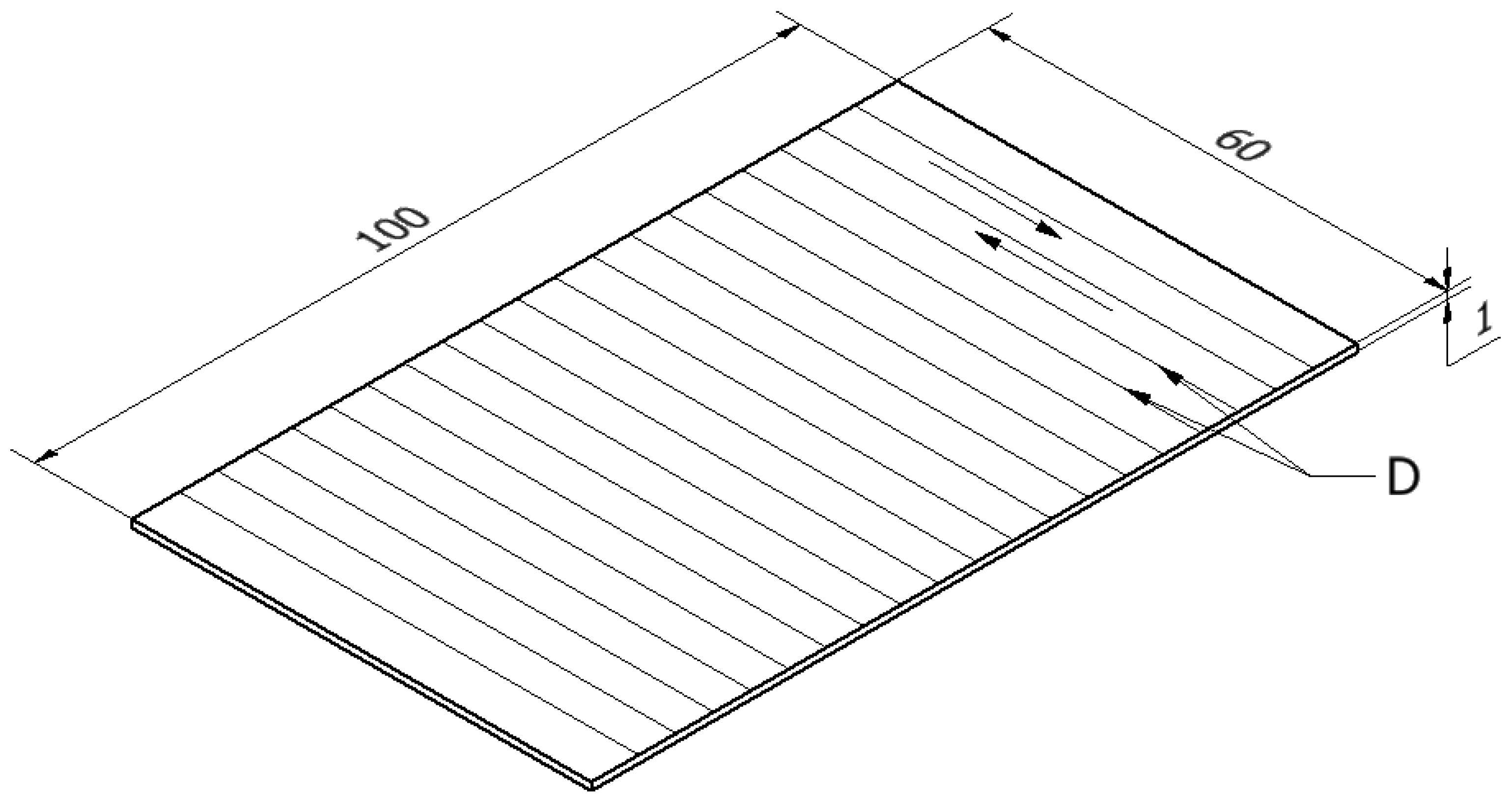
2.1. Experimental Cases Analyzed

The LBF tests studied in the present research correspond to a selection of the experiments carried out by Safari et al. [22] with the objective of attaining cylindrical surfaces from AISI 304 stainless-steel flat plates. These cases are considered representative since, as presented below, they cover a wide range of curvature radii of the final processed parts. Table 1 shows the specific cases to be analyzed along with the respective values of the laser power parameters, scanning speed, and distance between parallel irradiation lines. The CO2 laser beam diameter is 2 mm. To enhance laser beam absorption, the authors coated the sheet surfaces with graphite powder.
The dimensions of the sample are as follows: length (L)—100 mm; width (W)—60 mm; and thickness (T)—1 mm. A schematic representation of the sheet with the multiple zig-zag linear scanning paths is depicted in Figure 1.

2.2. Numerical Simulation

The thermomechanical formulation reported in [2], which is summarized in Box 1, is used in the numerical simulations carried out in the present research. This model is based on the associate-rate-independent plasticity theory considering large deformations, temperature-dependent material properties, and convection–radiation heat transfer through the sheet boundary. The von Mises yield function combined with the Hollomon isotropic hardening law is assumed to govern the material plastic behavior. In LBF, it is well documented that strain hardening is not relevant, while the yield strength, whose values strongly decrease with temperature, is a crucial variable with a marked influence on the sheet bending mechanism. Moreover, for simplicity, no phase transformations are taken into account in the analysis since they are widely recognized to not play a significant role in the thermomechanical response of the sheet during the laser beam irradiation [23].
Box 1. Thermomechanical formulation.
Governing equations (written in a Lagrangian description)
Continuity equation ρ J = ρ 0
Equation of motion · σ = 0
Energy balance equation ρ c T ˙ · q = 0
All equations are valid in the domain Ω × γ, where Ω is the spatial configuration of a body and γ is the time interval of interest, where:
J Determinant of the deformation gradient tensor F (where F 1 = I u , I being the unity tensor and u being the displacement field)
ρ : Density
: Spatial gradient operator
σ : Cauchy stress tensor (symmetric for the nonpolar case adopted in this work)
c : Specific heat capacity
T : Temperature of the body
q : Heat flux vector
Subscript 0: Denotes values in the initial configuration 0
The effects of body forces, acceleration, external heat source, and heat due to mechanical work are assumed to be negligible.
Thermal boundary conditions
The normal heat flux boundary condition of the energy balance (considered valid in   Γ f   x   γ , where   Γ f is the thermal boundary of the spatial configuration   ) is written as follows:
q · n = q c + q l
where q c is the convection–radiation normal heat flux, q l   is the normal heat flux provided by the laser beam, and n is the outward unit normal vector to   Γ f . The following laws are adopted:
q c = h c r ( T T e n v )
q l = a f l ( P l , d l )
where:
h c r : Convection–radiation heat transfer coefficient.
T e n v : Environmental temperature.
a : Absorption coefficient. It represents the fraction of incident energy that a material can absorb when irradiated by an external source.
f l : Laser heat flux distribution function, with P l and d l being the power and diameter of the laser beam, respectively. In this work, a Gaussian distribution is adopted: f l = 8 P l π d l 2 e 8 r 2 d l 2 , where r is the radial distance to the center of the laser beam.
A parallel convection–radiation mechanism is typically assumed, i.e., h c r = h c + h r , with h c   and h r being the convection and radiation coefficients, respectively. In this work, a constant value is adopted for h c , while the radiation is described in this context as    h r = ε σ B ( T + T e n v ) ( T 2 + T e n v 2 ) , where ε is the emissivity coefficient and σ B is the Boltzmann constant.
Constitutive relations
Isotropic Fourier’s law q = k T
Stress–strain relation σ = C : ( e e P e t h )
Thermal Almansi strain tensor e t h = 1 2 1 ( 1 a t h ) 2 / 3   I
where:
k : Conductivity coefficient, taken from Figure 2
C : Isotropic elastic constitutive tensor, Young’s modulus, and Poisson’s ratio taken from Figure 2
e e p : Almansi strain tensor (e = 1/2 ( I F T F 1 ) )
: Plastic Almansi strain tensor
a t h : Thermal dilatation function ( a t h = α t h T T o , with α t h being the thermal dilatation coefficient
Von Mises yield function F = 3 J 2 C Y 0 C
where J 2   is the second invariant of the deviatoric part of σ ( σ e q = 3 J 2 is the so-called equivalent or von Mises stress), C is the plastic isotropic hardening function, and C Y 0 is the yield strength defining the initial material elastic bound.
Hardening function C = A P e p ¯ n p
where:
A P :
n p :
e P ¯ :
Hardening coefficient
Hardening exponent
Equivalent plastic deformation
Plastic model
Flow rule          L v e p = λ ˙ F σ                    e p ¯ ˙ = λ ˙   F C
where:
  L v :
λ ˙ :
Lie (frame-indifferent) derivative
Plastic consistency parameter (derived from the condition F ˙ = 0 )
The plate is clamped in one end along its width. The initial temperature is set to the environmental temperature of 25 °C. The moving laser beam is assumed to induce a heat flux with a Gaussian distribution on the upper surface of the plate. The temperature-dependent thermomechanical properties of the AISI 304 stainless steel as well as the thermal parameters involved in the modeling were obtained from [2]. The choice of the absorption coefficient is based on the results reported by Cook et al. [24], where, according to Cook et al. [25], a constant value is adopted since relatively low inclination angles (i.e., angle between the directions of the laser beam and the normal vector to the sheet) are achieved in all the tests analyzed.
Figure 2. Comparison of experimental (E) and simulated (S) radius of curvature in terms of the total energy line for the tests analyzed. Trend lines corresponding to both results are also plotted. The red dotted lines represent the tendency of the Tests E, and the blue dotted lines represent the tendency of the Tests S.
Metals 15 00402 g002
This thermomechanical formulation is solved in the context of the finite element method via an in-house computational code widely validated in different LBF applications [2,8]. Due to the scanning path strategy used in the tests, a 3D uniformly distributed mesh composed of 216,000 hexahedral 8-noded isoparametric elements is used (300, 180, and 4 elements for the length, width, and thickness, respectively). A time step interval of 0.01 s is chosen for all cases.

3. Results and Discussion

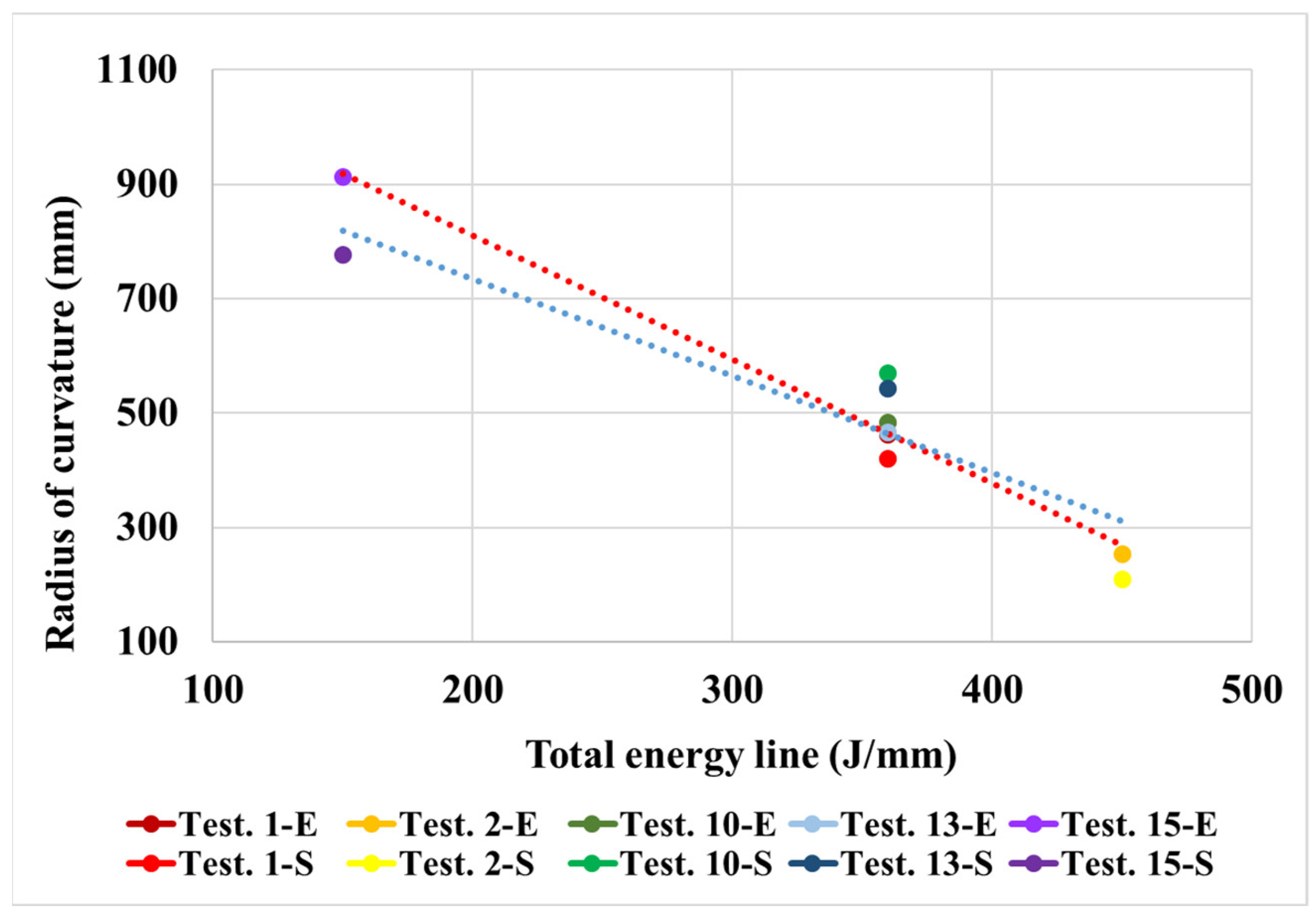
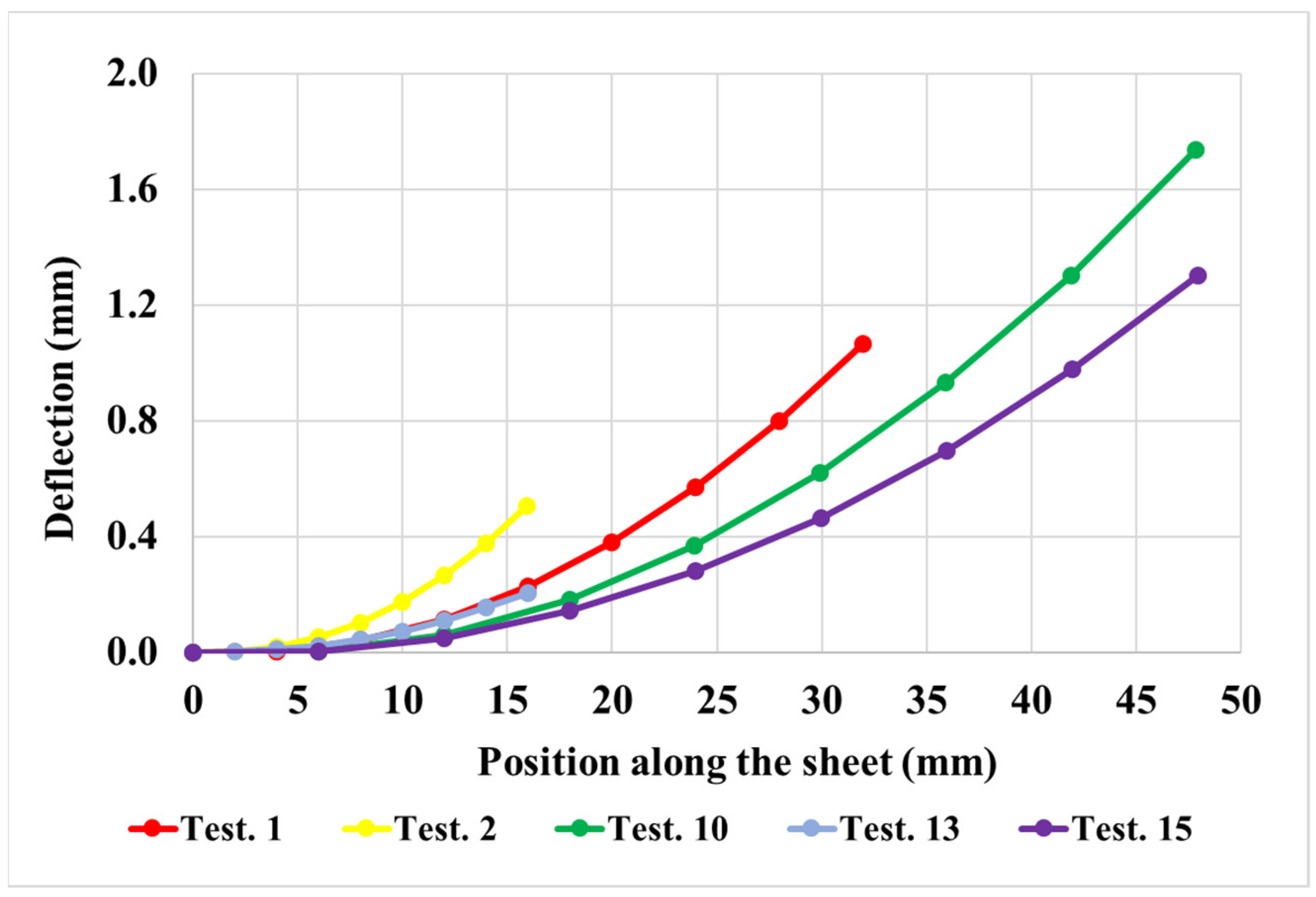
3.1. Experimental Validation of the Radius of Curvature

Table 2 shows the experimental measurements reported in [22] of the radius of curvature for the tests summarized in Table 1. It should be noted that only test number 1 was repeated three times, whereas the rest of the tests were carried out once. For test number 1, the difference between the maximum and minimum measured values of the radius of curvature with respect to the mean is about 20%. Table 2 also summarizes the corresponding numerical results obtained from the simulations performed in the present study together with the relative differences of these values with respect to the experimental ones. Overall, it can be seen that all simulations yield relative differences of less than 20% (in absolute values), which therefore indicates a reasonable approximation in the predictive capabilities of the model.
Table 3 displays the standard (i.e., single line) energy line values for the tests analyzed. In this multiple-pass application, it is clearly seen that these values do not present a relationship with the radius of curvature since tests with similar values of Q can generate very different levels of R. On the contrary, the radius of curvature is found in this work, as depicted in Figure 2, to inversely correlate with the total energy line definition, whose values are also included in Table 3. Both the experimental and numerical results show a decrease in the radius of curvature as the total thermal input increases. Therefore, it is seen that this trend in the radius of curvature involves the coupling effect of the three process parameters considered in the study. This behavior is consistent with what is expected in laser forming processes, where greater thermal inputs generally induce greater deformations, thus giving rise in these cases to smaller radii of curvature [9].

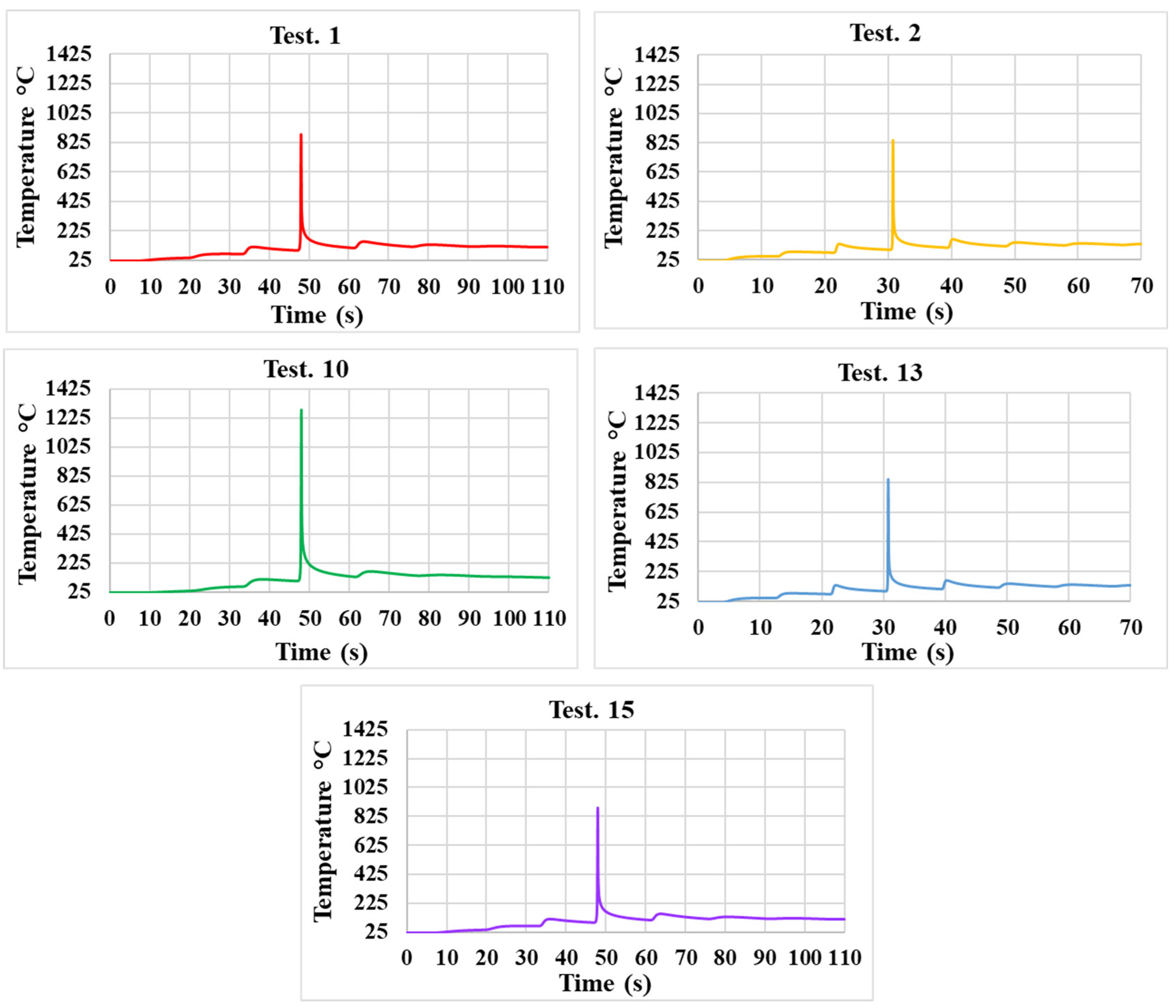
3.2. Influence of Processing Parameters on the Thermomechanical Material Response

Before presenting the results of this study, it is important to highlight that the finite element method (FEM) remains the most reliable tool for mechanical and thermal analysis in laser bending. This FEM approach differs from models based on artificial neural networks (ANNs), which although computationally more efficient, rely on experimental data and may not fully capture complex physical effects such as stress evolution and material property variations. For instance, Yamada et al. [26] developed an ANN to predict the deformation of sheets subjected to multi-pass laser bending, achieving accuracy comparable to experimental results. However, their predictions were based on empirical correlations without an underlying physical model. Similarly, Lambiase et al. [27] applied ANNs to laser bending, but without explicitly considering stress distribution or the cumulative effect of multiple passes. In contrast, the FEM model presented in this study enables a precise simulation of the deflection profile, incorporating nonlinear effects and the influence of material properties on deformation. Compared to other studies on three-dimensional surfaces, it shares key characteristics with the model proposed by Abolhasani et al. [20], such as thermomechanical coupling, heat flow modeling with a Gaussian distribution, and boundary conditions that include thermal dissipation through convection and radiation. Likewise, Gollo et al. [15] used a similar approach, integrating temperature-dependent material properties and obtaining numerical results that align well with experimental data. Both our model and those mentioned above have demonstrated strong agreement with the literature [28,29], thereby validating their accuracy and applicability in the study of laser bending.
Figure 3 shows the behavior of the vertical displacement profile of the plate in the analyzed tests after eight passes. It can be seen that for experiments with the distance between irradiation lines D, a greater displacement is obtained in those that present a greater value of total thermal energy input QN (compare Test 2 with Test 13 and Test 10 with Test 15). On the other hand, tests with a greater distance between irradiation lines (i.e., Tests 10 and 15) tend to generate a greater displacement in absolute terms. However, tests with a shorter distance between the irradiation lines (i.e., Tests 2 and 13), although requiring a greater number of passes, manage to induce more significant deformations in a shorter length of the piece. This is more apparent when comparing Tests 2 and 15, which have identical power and speed parameters but present a notable difference in the displacement values when the same position along the sheet length is analyzed. This behavior is reported in the study by Thomsen et al. [13], which states that a higher number of irradiations on the sample leads to increased deformation. It should additionally be mentioned that a nearly negligible warping was obtained in the numerical results of all the tests analyzed.
The tables presented below show results in sheet locations related to a generic laser beam trajectory since for all the N passes described in Table 3, the same response of the material is obtained according to the scanning strategy depicted in Figure 1.
Table 4 presents computed temperature values along the thickness of the plate when the laser beam is located at its half width for the tests analyzed. The denoted top face is the laser-irradiated one. It is observed that the temperatures reach high values on the scanning surface and decrease drastically as one moves towards the interior of the plate. This confirms the occurrence of a noticeable temperature gradient through the thickness, thus indicating the presence for all cases of the so-called temperature gradient mechanism (TGM), which is known to always generate controlled sheet bends towards the laser beam source [1]. This behavior has been widely reported in numerical finite element studies, such as those conducted by Naqvi [23] and Nath [29], who demonstrated that the formation of thermal gradients in the plate thickness is a key factor in controlling the angular deformation.
In general, and as expected, the values of the temperature profile attained in each test directly correlate with its energy line level. However, it can be seen that the distance between irradiation lines has a notable effect on the temperature, since tests with the same energy line value (e.g., Tests 2 and 15) achieved different temperatures, the lowest corresponding to the case with the greatest distance D (i.e., Test 15).
Figure 4 illustrates the temperature evolution over time for the different tests analyzed. In each case, the temperature is measured at a central point on the plate, located at a distance equivalent to four times the parameter D, to assess the effect of multiple pre- and post-irradiations. Each graph exhibits a characteristic trend, with a distinct temperature peak occurring when the laser irradiates the corresponding line at the analyzed position. According to studies conducted by other authors, this peak-shaped behavior in temperature is characteristic of laser forming processes [29]. Due to the localized application of heat, the temperature does not increase progressively. Even in multi-pass scanning processes [28,30], despite the considerable heat accumulation generated during successive irradiations, well-defined temperature peaks are still observed.
In all tests, a slight temperature increase is observed before the main irradiation, attributed to the thermal influence of the preceding lines. Similarly, cooling does not occur immediately after the temperature peak, as subsequent irradiation lines continue to contribute heat to the material. As expected, the tests with a higher line energy and a shorter distance between irradiation lines not only exhibit a higher peak temperature but also show more pronounced temperature increases both before and after the main irradiation.
It is also important to highlight that no temperatures higher than the melting one were reached in any case, which validates the assumption of not modeling the effect of latent absorption and release, associated with fusion and subsequent solidification of the material, respectively, during the process. In addition, the solid-state phase transformations that may occur in the heating and cooling stages are assumed to not have a significant influence on the thermomechanical response of the sheet. On the other hand, the moderate temperature levels achieved inhibit the appearance of strain-rate-dependent effects, thus validating the choice of the plastic model adopted in the numerical simulations [2].
Table 5 presents for the tests analyzed computed temperature T and final effective plastic deformation e p   values at the top surface of the plate when the laser beam is located at the beginning, middle, and end of the scanning path. For each test, the well-known boundary effect on the temperature profile is observed, i.e., the temperature exhibits a lower value at the beginning of the irradiation line, then it stabilizes, and it finally increases at the end of the scanning path. This behavior is clearly explained due to the different heat conduction conditions existing at these three locations. The boundary effect also affects the effective plastic deformation profile but with a less pronounced variation at the final edge position (with the exception of Test 10, in which the noticeably high temperature achieved in this case promotes the e p   evolution). Like the temperature response, the e p   values developed in each test directly correlate with its energy line value. However, in cases with the same energy line value (e.g., Tests 2 and 15), the distance between irradiation lines is seen to not have a relevant effect on the effective plastic deformation.

4. Conclusions

Finite element simulations of the laser forming process for the manufacture of cylindrical surfaces from AISI 304 stainless-steel plates have been presented. The obtained numerical results for the final radius of curvature showed a good approximation of the corresponding experimental measurements reported in the literature, with relative differences of less than 20%. It was found in this work that the radius of curvature presents an inverse relationship with respect to the total line energy, which, in turn, involves the coupling effect of the three process parameters considered in the analysis, i.e., laser power, scanning speed, and distance between parallel irradiation lines.
Regarding the influence of such parameters, it was confirmed that higher laser powers and lower scanning speeds—reflected in their combination through the line energy parameter—promoted higher temperatures and plastic deformations. Furthermore, the distance between irradiation lines was found to be a fundamental parameter in the formation of cylindrical surfaces, since it had a significant impact on displacement and induced deformation. Furthermore, in tests with the same line energy value, the distance between lines was found to have a notable impact on the temperature reached, with the lowest corresponding to the case with the largest distance D. However, in cases with the same line energy value, it was evident that the distance between irradiation lines did not significantly affect the effective plastic deformation.
Future research will be devoted to further study, both from an experimental and numerical perspective, of the evolution of induced deformation in the formation of cylindrical surfaces. In addition, the influence of the process parameters discussed in this research, as well as the impact of interaction with other factors on microstructural changes, will be analyzed.

Author Contributions

Conceptualization, D.C., D.J.C., M.A.C., C.G.-H. and A.M.; methodology, D.C., D.J.C., M.A.C., C.G.-H. and A.M.; software, D.J.C.; validation, D.C., D.J.C., M.A.C., C.G.-H. and A.M.; formal analysis, D.C., D.J.C., M.A.C., C.G.-H. and A.M.; investigation, D.C. and D.J.C.; resources, D.C.; data curation, D.C.; writing—original draft preparation, D.C. and D.J.C.; writing—review and editing, D.C., D.J.C., M.A.C., C.G.-H. and A.M.; visualization, D.C.; supervision, D.J.C.; project administration, D.J.C.; funding acquisition, D.J.C., M.A.C., C.G.-H. and A.M. All authors have read and agreed to the published version of the manuscript.

Funding

This research was financially supported by the Chilean Agency of Research and Development (ANID) through the FONDECYT Project No. 1220211.

Data Availability Statement

The raw data supporting the conclusions of this article will be made available by the authors on request.

Conflicts of Interest

The authors declare no conflicts of interest.

References

  1. Dixit, U.S.; Joshi, S.N.; Kant, R. Laser forming systems: A review. Int. J. Mechatron. Manuf. Syst. 2015, 8, 160–205. [Google Scholar] [CrossRef]
  2. Castillo, J.I.; Celentano, D.J.; Cruchaga, M.A.; García-Herrera, C.M. Characterization of strain rate effects in sheet laser forming. Comptes Rendus Mécanique 2018, 346, 794–805. [Google Scholar] [CrossRef]
  3. Dong, W.; Zhang, Y.; Bao, L.; Shin, K. Effects of laser scanning strategy on bending behavior and microstructure of DP980 steel. Materials 2024, 17, 2415. [Google Scholar] [CrossRef]
  4. Ablat, M.A.; Qattawi, A. Numerical simulation of sheet metal forming: A review. Int. J. Adv. Manuf. Technol. 2017, 89, 1235–1250. [Google Scholar] [CrossRef]
  5. Bachmann, A.L.; Dickey, M.D.; Lazarus, N. Making light work of metal bending: Laser forming in rapid prototyping. Quantum. Beam Sci. 2020, 4, 44. [Google Scholar] [CrossRef]
  6. Zhang, Z.; Shen, H. Numerical study on deformation behaviors in intersecting rectilinear laser bending. J. Manuf. Process. 2024, 127, 98–106. [Google Scholar] [CrossRef]
  7. Khandai, B.K.; Gopinath, M. Modelling and monitoring of scaling effects in multi-scan laser forming. Opt. Laser Technol. 2025, 186, 112712. [Google Scholar] [CrossRef]
  8. Cook, F.; Celentano, D.; Ramos-Grez, J. Experimental-numerical methodology for the manufacturing of cranial prosthesis via laser forming. Int. J. Adv. Manuf. Technol. 2016, 86, 2187–2196. [Google Scholar]
  9. Pennuto, J.; Choi, J. Characteristics of parallel irradiations in laser forming of stainless steel. J. Laser Appl. 2005, 17, 235–242. [Google Scholar] [CrossRef]
  10. Shen, H.; Zhou, W.; Wang, H. Laser forming of doubly curved plates using minimum energy principle and comprehensive strain control. Int. J. Mech. Sci. 2018, 145, 42–52. [Google Scholar] [CrossRef]
  11. Vásquez Ojeda, C.; Ramos Grez, J. Bending of stainless steel thin sheets by a raster scanned low power CO2 laser. J. Mater. Process. Technol. 2009, 209, 2641–2647. [Google Scholar] [CrossRef]
  12. Maji, K.; Pratihar, D.K.; Nath, A.K. Experimental investigations, modeling, and optimization of multi-scan laser forming of AISI 304 stainless steel sheet. Int. J. Adv. Manuf. Technol. 2016, 83, 1441–1455. [Google Scholar] [CrossRef]
  13. Thomsen, A.N.; Kristiansen, E.; Kristiansen, M.; Endelt, B. Investigation of the profile of laser bends with variable scan distance. Procedia Manuf. 2019, 36, 192–199. [Google Scholar] [CrossRef]
  14. Shahabad, S.I.; Naeini, H.M.; Roohi, A.H.; Tavakoli, A.; Nasrollahzade, M. Experimental investigation of laser forming process to produce dome-shaped products. Int. J. Adv. Manuf. Technol. 2017, 90, 1051–1057. [Google Scholar] [CrossRef]
  15. Gollo, M.H.; Nadi, G.; Mehdi, M.; Abbaszadeh, M. Experimental and numerical study of spiral scan paths on cap laser forming. J. Laser Appl. 2015, 27, 012002. [Google Scholar] [CrossRef]
  16. Safari, M.; Farzin, M. Experimental investigation of laser forming of a saddle shape with spiral irradiating scheme. Opt. Laser Technol. 2015, 66, 146–150. [Google Scholar] [CrossRef]
  17. Safari, M.; Farzin, M.; Mostaan, H. A novel method for laser forming of two-step bending of a dome-shaped part. Iran. J. Mater. Form. 2017, 4, 1–14. [Google Scholar] [CrossRef]
  18. Nunobiki, M.; Okuda, K.; Hourai, K.; Shizuka, H. Bending of pure titanium sheet to curved surface shape by laser forming technique. Adv. Mater. Res. 2010, 126, 388–393. [Google Scholar] [CrossRef]
  19. Abolhasani, D.; Seyedkashi, S.M.H.; Kim, Y.T.; Gollo, M.H.; Moon, Y.H. A double raster laser scanning strategy for rapid die-less bending of 3D shape. J. Mater. Res. Technol. 2019, 8, 4741–4756. [Google Scholar] [CrossRef]
  20. Abolhasani, D.; Seyedkashi, S.M.H.; Hoseinpour Gollo, M.; Moon, Y.H. Effects of laser beam parameters on bendability and microstructure of stainless steel in three-dimensional laser forming. Appl. Sci. 2019, 9, 4463. [Google Scholar] [CrossRef]
  21. Wang, X.; Shi, Y.; Guo, Y.; Wang, Q. Design of 3D surface laser forming process. J. Manuf. Process. 2022, 73, 306–315. [Google Scholar] [CrossRef]
  22. Safari, M.; Miralaa, S.M.; Alves de Sousa, R. Experimental investigation of the effects of process parameters on the radius of curvature in laser forming process of cylindrical surfaces. Metals 2022, 13, 56. [Google Scholar] [CrossRef]
  23. Naqvi, S.M.R.; Haidry, A.A.; Xie, D.; Ahmad, S.; Liu, Y.; Chen, Y.; Jiao, C.; Jamil, M.; Yan, C.; Shen, L. Influence of laser beam process parameters on the bending ability of Ti-6Al-4V titanium alloy sheets. Int. J. Adv. Manuf. Technol. 2024, 133, 3445–3460. [Google Scholar] [CrossRef]
  24. Cook, F.; Jacobsen, V.; Celentano, D.; Ramos-Grez, J. Characterization of the absorptance of laser irradiated steel sheets. J. Laser Appl. 2015, 27, 032006. [Google Scholar] [CrossRef]
  25. Cook, F.; Miró, L.; Celentano, D.; Ramos-Grez, J. Effect of inclination angle on the absorptance of a graphite-coated cold-rolled steel sheet irradiated by laser. J. Laser Appl. 2016, 28, 022001. [Google Scholar] [CrossRef]
  26. Yamada, K.; Kushida, N.; Wada, S.; Sentoku, E.; Tanaka, R.; Sekiya, K. A machine learning approach for simulation of multi-stage laser forming process. J. Adv. Mech. Des. Syst. Manuf. 2023, 17, JAMDSM0006. [Google Scholar] [CrossRef]
  27. Lambiase, F.; Di Ilio, A.; Paoletti, A. Productivity in multi-pass laser forming of thin AISI 304 stainless steel sheets. Int. J. Adv. Manuf. Technol. 2016, 86, 259–268. [Google Scholar] [CrossRef]
  28. Nath, U.; Yadav, V.; Purohit, R. Finite element analysis of AM30 magnesium alloy sheet in the laser bending process. Adv. Mater. Process. Technol. 2022, 8, 1803–1815. [Google Scholar] [CrossRef]
  29. Nath, U.; Yadav, V.; Bhadauria, S.S. Effects of workpiece size on bending angle in laser forming of Al 6061-T6 sheet. Mater. Today: Proc. 2024, 113, 307–313. [Google Scholar] [CrossRef]
  30. Fetene, B.N.; Kumar, V.; Dixit, U.S.; Echempati, R. Numerical and experimental study on multi-pass laser bending of AH36 steel strips. Opt. Laser Technol. 2018, 99, 291–300. [Google Scholar] [CrossRef]
Figure 1. Schematic representation of the LBF sample (dimensions in mm).
Metals 15 00402 g001
Figure 3. Computed average deflection profile (at the half width after eight passes) of the plate for the tests analyzed.
Metals 15 00402 g003
Figure 4. Evolution of temperature during laser irradiation.
Metals 15 00402 g004
Table 1. Selected cases analyzed. Adapted from Ref. [20].
Test NumberLaser Beam Power, P
(W)
Scanning Velocity, V
(mm/s)
Distance Between
Irradiation Lines, D (mm)
17254
27282
1010856
133652
157286
Table 2. Experimental (E) and simulated (S) radius of curvature R for the tests analyzed.
Test NumberR (E)
(mm)
R (S)
(mm)
Relative   Difference ,   R E R ( S ) R ( E ) 100
(%)
14634209.2
225421017.2
10484571−17.8
13467544−16.5
1591377615.0
Table 3. Energy line for the tests analyzed.
Test
Number
Energy Line, Q = P / V
(J/mm)
Number of Passes,
N = L / D
Total Energy Line,
Q N = N   Q
(J/mm)
114.425360
29.050450
1021.617360
137.250360
159.016144
Table 4. Computed temperature along the thickness (when the laser beam is located at the middle of the scanning path) for the tests analyzed.
Test Number Energy   Line ,   Q
(J/mm)
Temperature (°C)
Top FaceHalf ThicknessBottom Face
114.4880346290
29.0842319266
1021.61279489403
137.2501216187
159.0748241191
Table 5. Computed temperature and final effective plastic deformation at the top face (when the laser beam is located at the beginning, middle, and end of the scanning path) for the tests analyzed.
Test
Number
Energy   Line ,   Q
(J/mm)
Initial EdgeHalf WidthFinal Edge
T (°C) e p T (°C) e p T (°C) e p
114.48100.0138800.01910190.019
29.07790.0118420.0189310.016
1021.67820.01712790.03314840.044
137.24650.0035010.0075790.007
159.03740.0057480.0158880.016
Disclaimer/Publisher’s Note: The statements, opinions and data contained in all publications are solely those of the individual author(s) and contributor(s) and not of MDPI and/or the editor(s). MDPI and/or the editor(s) disclaim responsibility for any injury to people or property resulting from any ideas, methods, instructions or products referred to in the content.

