
Electrochemical Evaluation of Strontium-Doped Micro-Arc Oxidation Surfaces on Titanium


Abstract
:1. Introduction
2. Materials and Methods
3. Results and Discussion
4. Conclusions
Author Contributions
Funding
Data Availability Statement
Conflicts of Interest
References
- Cui, S.; Shi, A.; Xie, Y.; Yu, H.; Wei, Y.; Yang, L.; Qin, G.; Zhang, E. Feasibility study on Ti-15Mo-7Cu with low elastic modulus and high antibacterial property. BioMetals 2022, 35, 1225. [Google Scholar]
- Rodrigues, D.C.; Robert, U.M.; Jacobs, J.J.; Gilbert, J.L.; Urban, R.M. In vivo severe corrosion and hydrogen embrittlement of retrieved modular body titanium alloy hip-implants. J. Biomed. Mater. Res. Part B Appl. Biomater. 2010, 88, 206. [Google Scholar] [CrossRef] [PubMed]
- Li, G.; Ma, F.; Liu, P.; Qi, S.; Li, W.; Zhang, K.; Chen, X. Review of micro-arc oxidation of titanium alloys: Mechanism, properties and applications. J. Alloys Compd. 2023, 948, 169773. [Google Scholar]
- Capuccini, C.; Torricelli, P.; Sima, F.; Boanini, E.; Ristoscu, C.; Bracci, B.; Socol, G.; Fini, M.; Mihailescu, I.N.; Bigi, A. Strontium-substituted hydroxyapatite coatings synthesized by pulsed-laser deposition: In vitro osteoblast and osteoclast response. Acta Biomater. 2008, 4, 1885. [Google Scholar] [PubMed]
- Costa, A.I.; Gemini-Piperni, S.; Alves, A.C.; Costa, N.A.; Checca, N.R.; Leite, P.E.; Rocha, L.A.; Pinto, A.M.P.; Toptan, F.; Rossi, A.L.; et al. TiO2 bioactive implant surfaces doped with specific amount of Sr modulate mineralization. Mater. Sci. Eng. C 2021, 120, 111735. [Google Scholar]
- Liu, L.; Ma, F.; Kang, B.; Liu, P.; Qi, S.; Li, W.; Zhang, K.; Chen, X. Preparation and mechanical and biological performance of the Sr-containing microarc oxidation layer on titanium implants. Surf. Coatings Technol. 2023, 463, 129530. [Google Scholar]
- Liu, L.; Ma, F.; Liu, P.; Qi, S.; Li, W.; Zhang, K.; Chen, X. Preparation and antibacterial properties of ZnSr-doped micro-arc oxidation coatings on titanium. Surf. Coatings Technol. 2023, 462, 129469. [Google Scholar]
- Nguyen, A.-N.N.; Kung, K.-C.C.; Chen, K.-C.C.; Hsu, C.-W.W.; Huang, C.-L.L.; Lee, T.-M.M. Characteristics and biological responses of selective laser melted Ti6Al4V modified by micro-arc oxidation. J. Dent. Sci. 2024, 19, 1426. [Google Scholar]
- Zhang, Z.-Y.; Huang, T.-Y.; Zhai, D.-J.; Wang, H.-B.; Feng, K.-Q.; Xiang, L. Study on strontium doped bioactive coatings on titanium alloys surfaces by micro-arc oxidation. Surf. Coatings Technol. 2022, 451, 129045. [Google Scholar] [CrossRef]
- Lu, W.; Zhou, C.; Ma, Y.; Li, J.; Chen, Y.; Jiang, J.; Dong, L.; He, F. Improved osseointegration of strontium-modified titanium implant by regulating angiogenesis and macrophage polarization. Biomater. Sci. 2022, 10, 2198–2214. [Google Scholar] [CrossRef]
- Liu, W.; Wang, D.; He, G.; Li, T.; Zhang, X. A novel porous titanium with engineered surface for bone defect repair in load-bearing position. J. Biomed. Mater. Res. Part A 2024, 112, 1083. [Google Scholar]
- Shen, X.; Fang, K.; Yie, K.H.R.; Zhou, Z.; Shen, Y.; Wu, S.; Zhu, Y.; Deng, Z.; Ma, P.; Ma, J.; et al. High proportion strontium-doped micro-arc oxidation coatings enhance early osseointegration of titanium in osteoporosis by anti-oxidative stress pathway. Bioact. Mater. 2022, 10, 405. [Google Scholar]
- Wang, D.; Chen, M.W.; Wei, Y.J.; Geng, W.B.; Hu, Y.; Luo, Z.; Cai, K.Y. Construction of Wogonin Nanoparticle-Containing Strontium-Doped Nanoporous Structure on Titanium Surface to Promote Osteoporosis Fracture Repair. Adv. Healthc. Mater. 2022, 11, 2201405. [Google Scholar]
- Zhang, W.; Cao, H.; Zhang, X.; Li, G.; Chang, Q.; Zhao, J.; Qiao, Y.; Ding, X.; Yang, G.; Liu, X.; et al. A strontium-incorporated nanoporous titanium implant surface for rapid osseointegration. Nanoscale 2016, 8, 5291. [Google Scholar]
- Liu, W.; Cheng, M.; Wahafu, T.; Zhao, Y.; Qin, H.; Wang, J.; Zhang, X.; Wang, L. The in vitro and in vivo performance of a strontium-containing coating on the low-modulus Ti35Nb2Ta3Zr alloy formed by micro-arc oxidation. J. Mater. Sci. Mater. Med. 2015, 26, 1. [Google Scholar]
- Yu, J.-M.; Cho, H.-R.; Choe, H.-C. Electrochemical characteristics of Sr/Si-doped hydroxyapatite coating on the Ti alloy surface via plasma electrolytic oxidation. Thin Solid Films 2022, 746, 139124. [Google Scholar]
- Kung, K.C.; Lee, T.M.; Lui, T.S. Bioactivity and corrosion properties of novel coatings containing strontium by micro-arc oxidation. J. Alloys Compd. 2010, 508, 384. [Google Scholar]
- Costa, A.I.; Viana, F.; Toptan, F. Preliminary tribocorrosion evaluation of bio-functionalized Ti doped with Ca-P-Sr. Mater. Lett. 2021, 283, 128775. [Google Scholar]
- Albella, J.M.; Montero, I.; Martinez-Duart, J.M. A theory of avalanche breakdown during anodic oxidation. Electrochim. Acta 1987, 32, 255. [Google Scholar]
- Cardoso, G.C.; Grandini, C.R.; Rau, J.V. Comprehensive review of PEO coatings on titanium alloys for biomedical implants. J. Mater. Res. Technol. 2024, 31, 311. [Google Scholar]
- Ikonopisov, S. Theory of electrical breakdown during formation of barrier anodic films. Electrochim. Acta 1977, 22, 1077. [Google Scholar]
- Ding, J.; Liang, J.; Hu, L.T.; Hao, J.C.; Xue, Q.J. Effects of sodium tungstate on characteristics of microarc oxidation coatings formed on magnesium alloy in silicate-KOH electrolyte. Trans. Nonferrous Met. Soc. China 2007, 17, 244. [Google Scholar]
- Hussein, R.O.; Nie, X.; Northwood, D.O. An investigation of ceramic coating growth mechanisms in plasma electrolytic oxidation (PEO) processing. Electrochim. Acta 2013, 112, 111. [Google Scholar]
- Ahounbar, E.; Khoei, S.M.M.; Omidvar, H. Characteristics of in-situ synthesized Hydroxyapatite on TiO2 ceramic via plasma electrolytic oxidation. Ceram. Int. 2019, 45, 3118. [Google Scholar]
- Venkateswarlu, K.; Rameshbabu, N.; Sreekanth, D.; Sandhyarani, M.; Bose, A.C.; Muthupandi, V.; Subramanian, S. Role of electrolyte chemistry on electronic and in vitro electrochemical properties of micro-arc oxidized titania films on Cp Ti. Electrochim. Acta 2013, 105, 468. [Google Scholar]
- van Hengel, I.A.J.; Laçin, M.; Minneboo, M.; Fratila-Apachitei, L.E.; Apachitei, I.; Zadpoor, A.A. The effects of plasma electrolytically oxidized layers containing Sr and Ca on the osteogenic behavior of selective laser melted Ti6Al4V porous implants. Mater. Sci. Eng. C 2021, 124, 112074. [Google Scholar]
- Ochiabuto, K.; Pitts, H.; Cao, Y.; Meletis, E. Quantitative modeling of oxide growth in plasma electrolytic oxidation of titanium. Mater. Chem. Phys. 2024, 323, 129633. [Google Scholar]
- Kaseem, M.; Fatimah, S.; Nashrah, N.; Ko, Y.G. Recent progress in surface modification of metals coated by plasma electrolytic oxidation: Principle, structure, and performance. Prog. Mater. Sci. 2021, 117, 100735. [Google Scholar]
- Kuroda, P.A.B.; Rossi, M.C.; Grandini, C.R.; Afonso, C.R.M. Assessment of applied voltage on the structure, pore size, hardness, elastic modulus, and adhesion of anodic coatings in Ca-, P-, and Mg-rich produced by MAO in Ti–25Ta–Zr alloys. J. Mater. Res. Technol. 2023, 26, 4656. [Google Scholar]
- Sato, M.; Chen, P.; Tsutsumi, Y.; Shiota, M.; Hanawa, T.; Kasugai, S. Effect of strontium ions on calcification of preosteoblasts cultured on porous calcium-and phosphate-containing titanium oxide layers formed by micro-arc oxidation. Dent. Mater. J. 2016, 35, 627. [Google Scholar] [CrossRef]
- Baron-Wiecheć, A.; Curioni, M.; Arrabal, R.; Matykina, E.; Skeldon, P.; Thompson, G.E. Plasma electrolytic oxidation of coupled light metals. Trans. IMF 2013, 91, 107. [Google Scholar] [CrossRef]
- Clyne, T.W.; Troughton, S.C. A review of recent work on discharge characteristics during plasma electrolytic oxidation of various metals. Int. Mater. Rev. 2019, 64, 127. [Google Scholar] [CrossRef]
- Zhai, D.-J.; Feng, K.-Q. Preparation of micro/nano-structured ceramic coatings on Ti6Al4V alloy by plasma electrolytic oxidation process. Trans. Nonferrous Met. Soc. China 2019, 29, 2546. [Google Scholar] [CrossRef]
- Yu, J.M.; Choe, H.C. Morphology changes and bone formation on PEO-treated Ti-6Al-4V alloy in electrolyte containing Ca, P, Sr, and Si ions. Appl. Surf. Sci. 2019, 477, 121. [Google Scholar] [CrossRef]
- Nan, K.; Wu, T.; Chen, J.; Jiang, S.; Huang, Y.; Pei, G. Strontium doped hydroxyapatite film formed by micro-arc oxidation. Mater. Sci. Eng. C 2009, 29, 1554. [Google Scholar] [CrossRef]
- Gowtham, S.; Arunnellaiappan, T.; Rameshbabu, N. An investigation on pulsed DC plasma electrolytic oxidation of cp-Ti and its corrosion behaviour in simulated body fluid. Surf. Coatings Technol. 2016, 301, 63. [Google Scholar]
- Alves, A.C.; Wenger, F.; Ponthiaux, P.; Celis, J.P.; Pinto, A.M.; Rocha, L.A.; Fernandes, J.C.S. Corrosion mechanisms in titanium oxide-based films produced by anodic treatment. Electrochim. Acta 2017, 234, 16. [Google Scholar] [CrossRef]
- Mariano, N.A.; Oliveira, R.G.; Braga, E.I.; Rigo, E.C.S. Corrosion characterization of titanium alloys by electrochemical techniques in artificial saliva and SBF solution. Key Eng. Mater. 2009, 396–398, 315. [Google Scholar] [CrossRef]
- Arunnellaiappan, T.; Babu, N.K.; Krishna, L.R.; Rameshbabu, N. Influence of frequency and duty cycle on microstructure of plasma electrolytic oxidized AA7075 and the correlation to its corrosion behavior. Surf. Coatings Technol. 2015, 280, 136. [Google Scholar] [CrossRef]
- De Assis, S.L.; Wolynec, S.; Costa, I. Corrosion characterization of titanium alloys by electrochemical techniques. Electrochim. Acta 2006, 51, 1815. [Google Scholar] [CrossRef]
- Lu, Y.; Wan, P.; Tan, L.; Zhang, B.; Yang, K.; Lin, J. Preliminary study on a bioactive Sr containing Ca-P coating on pure magnesium by a two-step procedure. Surf. Coatings Technol. 2014, 252, 79. [Google Scholar] [CrossRef]
- Park, I.S.; Woo, T.G.; Jeon, W.Y.; Park, H.H.; Lee, M.H.; Bae, T.S.; Seol, K.W. Surface characteristics of titanium anodized in the four different types of electrolyte. Electrochim. Acta 2007, 53, 863. [Google Scholar]
- Oliveira, F.G.; Ribeiro, A.R.; Perez, G.; Archanjo, B.S.; Gouvea, C.P.; Araújo, J.R.; Campos, A.P.C.; Kuznetsov, A.; Almeida, C.M.; Maru, M.M.; et al. Understanding growth mechanisms and tribocorrosion behaviour of porous TiO2 anodic films containing calcium, phosphorous and magnesium. Appl. Surf. Sci. 2015, 341, 1. [Google Scholar] [CrossRef]
- Park, M.G.; Choe, H.C. Corrosion behaviors of bioactive element coatings on PEO-treated Ti-6Al-4V alloys. Surf. Coatings Technol. 2019, 376, 44. [Google Scholar]
- Mashtalyar, D.V.; Nadaraia, K.V.; Gnedenkov, A.S.; Imshinetskiy, I.M.; Piatkova, M.A.; Pleshkova, A.I.; Belov, E.A.; VFilonina, S.; Suchkov, S.N.; Sinebryukhov, S.L.; et al. Bioactive Coatings Formed on Titanium by Plasma Electrolytic Oxidation: Composition and Properties. Materials 2020, 13, 4121. [Google Scholar] [CrossRef] [PubMed]
- Han, J.; Cheng, Y.; Tu, W.; Zhan, T.-Y.; Cheng, Y. The black and white coatings on Ti-6Al-4V alloy or pure titanium by plasma electrolytic oxidation in concentrated silicate electrolyte. Appl. Surf. Sci. 2018, 428, 684. [Google Scholar]
- Shokouhfar, M.; Dehghanian, C.; Montenero, A.; Baradaran, A. Preparation of ceramic coating on Ti substrate by plasma electrolytic oxidation in different electrolytes and evaluation of its corrosion resistance: Part II. Appl. Surf. Sci. 2012, 258, 2416. [Google Scholar]
- Fazel, M.; Salimijazi, H.R.; Golozar, M.A.; Jazi, M.R.G. A comparison of corrosion, tribocorrosion and electrochemical impedance properties of pure Ti and Ti6Al4V alloy treated by micro-arc oxidation process. Appl. Surf. Sci. 2015, 324, 751. [Google Scholar]
- Alves, A.C.; Costa, A.I.; Toptan, F.; Alves, J.L.; Leonor, I.; Ribeiro, E.; Reis, R.L.; Pinto, A.M.P.; Fernandes, J.C.S. Effect of bio-functional MAO layers on the electrochemical behaviour of highly porous Ti. Surf. Coatings Technol. 2020, 386, 125487. [Google Scholar]
- Wang, Y.M.; Guo, L.X.; Ouyang, J.H.; Zhou, Y.; Jia, D.C. Interface adhesion properties of functional coatings on titanium alloy formed by microarc oxidation method. Appl. Surf. Sci. 2009, 255, 6875–6880. [Google Scholar]
- Hu, Y.; Wang, Z.; Ai, J.; Bu, S.; Liu, H. Preparation of Coating on the Titanium Surface by Micro-Arc Oxidation to Improve Corrosion Resistance. Coatings 2021, 11, 230. [Google Scholar] [CrossRef]
- Hsu, C.H.; Mansfeld, F. Technical Note: Concerning the Conversion of the Constant Phase Element Parameter Y 0 into a Capacitance. Corrosion 2001, 57, 747. [Google Scholar]
- Orazem, M.E.; Tribollet, B. Electrochemical Impedance Spectroscopy; John Wiley & Sons: Hoboken, NJ, USA, 2017. [Google Scholar]
- Wypych, A.; Bobowska, I.; Tracz, M.; Opasinska, A.; Kadlubowski, S.; Krzywania-Kaliszewska, A.; Grobelny, J.; Wojciechowski, P. Dielectric properties and characterisation of titanium dioxide obtained by different chemistry methods. J. Nanomater. 2014, 2014, 124814. [Google Scholar]
- Lundstrom, J.; Rinehart, L.; Pate, R.; Smith, T.; Krogh, M.; Huebner, W. Measurement of the dielectric strength of titanium dioxide ceramics. In Proceedings of the 12th IEEE International Pulsed Power Conference, Monterey, CA, USA, 27–30 June 1999; IEEE: Piscataway, NJ, USA, 1999; pp. 10–12. [Google Scholar]
- Çaha, I.; Alves, A.C.; Chirico, C.; Pinto, A.M.; Tsipas, S.; Gordo, E.; Bondarchuk, O.; Deepak, F.L.; Toptan, F. Atomic–scale investigations of passive film formation on Ti-Nb alloys. Appl. Surf. Sci. 2023, 615, 156282. [Google Scholar]
- Blackwood, D.J. Influence of the space-charge region on electrochemical impedance measurements on passive oxide films on titanium. Electrochim. Acta 2000, 46, 563. [Google Scholar]


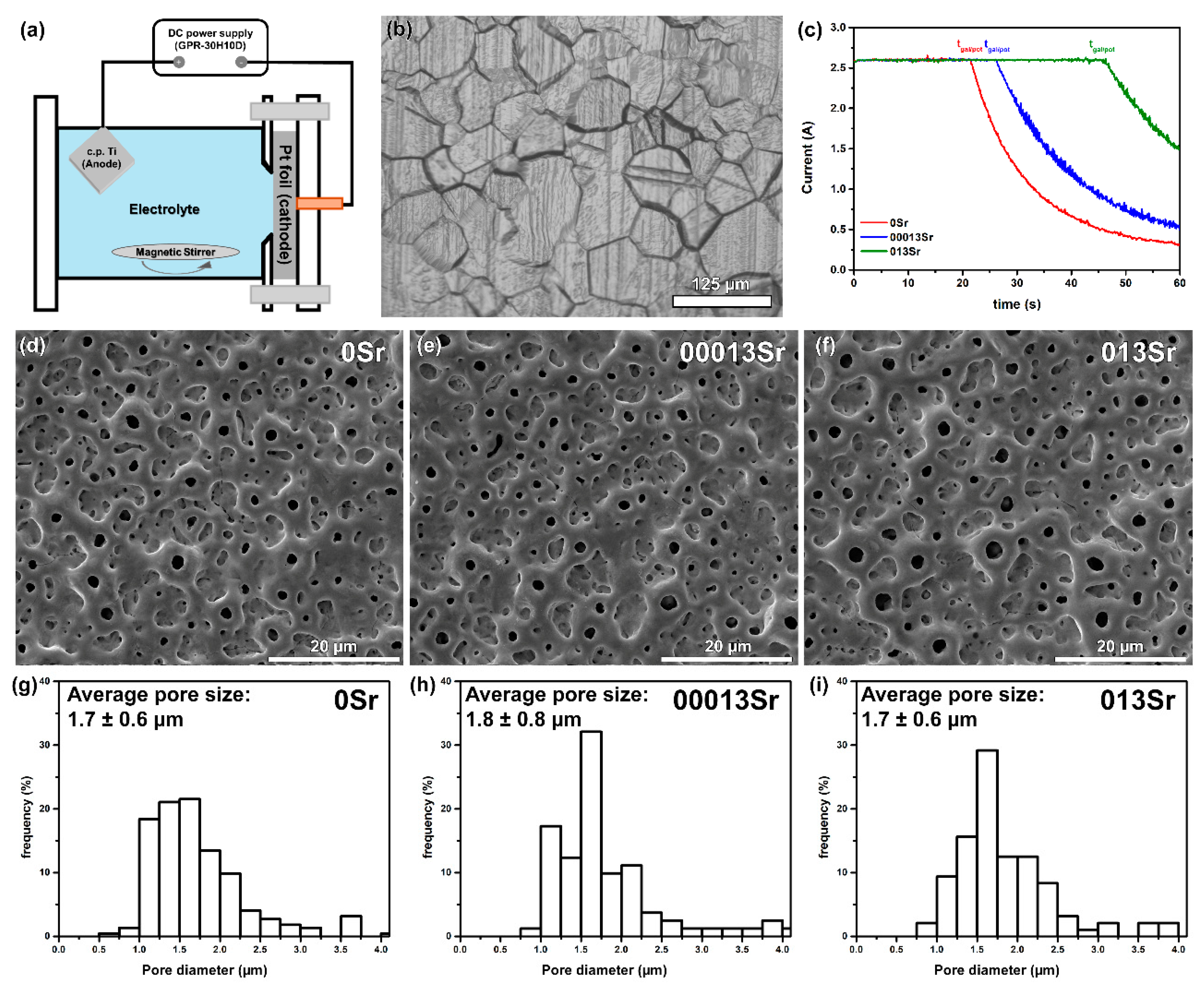
| Groups | Electrolyte Composition | Conductivity (mS/cm) |
|---|---|---|
| Ti | – | – |
| 0Sr | 0.35 M CA + 0.02 M β-GP | 23.92 ± 0.08 |
| 00013Sr | 0.35 M CA + 0.02 M β-GP + 0.0013 M Sr | 26.76 ± 0.16 |
| 013Sr | 0.35 M CA+ 0.02 M β-GP+ 0.13 M Sr | 31.14 ± 0.09 |
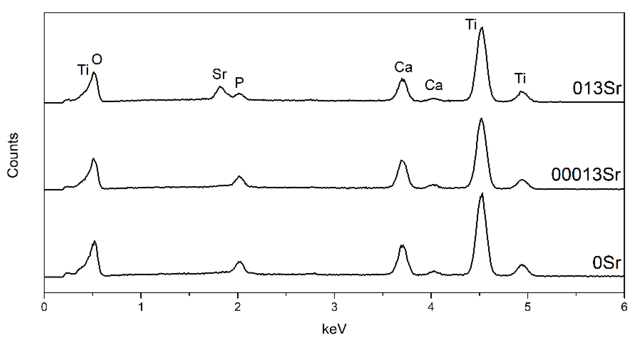
| Groups | Ca | P | Sr | Ca/P |
|---|---|---|---|---|
| 0Sr | 5.63 ± 1.35 | 1.99 ± 0.37 | – | 2.81 ± 0.18 |
| 00013Sr | 8.43 ± 0.06 | 2.57 ± 0.08 | 0.29 ± 0.03 | 3.28 ± 0.12 |
| 013Sr | 6.78 ± 0.08 | 1.71 ± 0.02 | 2.29 ± 0.06 | 3.95 ± 0.08 |
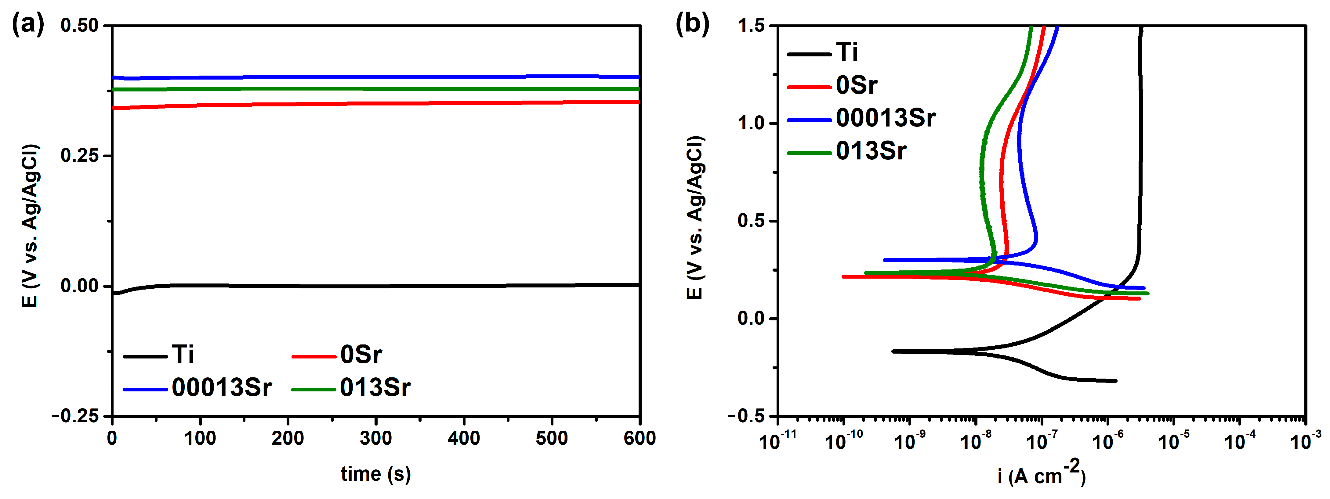
| EOCP (VAg/AgCl) | E(i=0) (VAg/AgCl) | ipass (µA cm−2) | |
|---|---|---|---|
| Ti | −0.015 ± 0.053 | −0.169 ± 0.053 | 3.093 ± 0.489 |
| 0Sr | 0.315 ± 0.077 | 0.198 ± 0.025 | 0.031 ± 0.007 |
| 00013Sr | 0.393 ± 0.022 | 0.257 ± 0.052 | 0.022 ± 0.006 |
| 013Sr | 0.376 ± 0.017 | 0.217 ± 0.037 | 0.014 ± 0.002 |
| C1/2wall (µF cm−2) | n1/2wall | Cwall (µF cm−2) | nwall | Rbf (MΩ cm2) | Cbf (µF cm−2) | nbf | χ2 | |
|---|---|---|---|---|---|---|---|---|
| Ti | – | – | – | – | 0.89 ± 0.39 | 18.87 ± 2.45 | 0.95 ± 0.01 | <10−3 |
| 0Sr | 5.72 ± 2.33 | 0.85 ± 0.07 | 0.64 ± 0.38 | 0.79 ± 0.05 | 1.51 ± 0.35 | 5.09 ± 1.35 | 0.70 ± 0.05 | <10−4 |
| 00013Sr | 7.58 ± 1.56 | 0.81 ± 0.02 | 0.36 ± 0.10 | 0.79 ± 0.03 | 1.91 ± 1.25 | 5.64 ± 1.48 | 0.84 ± 0.05 | <10−4 |
| 013Sr | 8.20 ± 1.20 | 0.84 ± 0.01 | 0.85 ± 0.14 | 0.76 ± 0.02 | 1.51 ± 0.89 | 3.08 ± 0.27 | 0.83 ± 0.01 | <10−4 |
Disclaimer/Publisher’s Note: The statements, opinions and data contained in all publications are solely those of the individual author(s) and contributor(s) and not of MDPI and/or the editor(s). MDPI and/or the editor(s) disclaim responsibility for any injury to people or property resulting from any ideas, methods, instructions or products referred to in the content. |
© 2025 by the authors. Licensee MDPI, Basel, Switzerland. This article is an open access article distributed under the terms and conditions of the Creative Commons Attribution (CC BY) license (https://creativecommons.org/licenses/by/4.0/).
Share and Cite
Alves, A.C.; Durães, C.; Toptan, F. Electrochemical Evaluation of Strontium-Doped Micro-Arc Oxidation Surfaces on Titanium. Metals 2025, 15, 390. https://doi.org/10.3390/met15040390
Alves AC, Durães C, Toptan F. Electrochemical Evaluation of Strontium-Doped Micro-Arc Oxidation Surfaces on Titanium. Metals. 2025; 15(4):390. https://doi.org/10.3390/met15040390
Chicago/Turabian StyleAlves, Alexandra C., Carolina Durães, and Fatih Toptan. 2025. "Electrochemical Evaluation of Strontium-Doped Micro-Arc Oxidation Surfaces on Titanium" Metals 15, no. 4: 390. https://doi.org/10.3390/met15040390
APA StyleAlves, A. C., Durães, C., & Toptan, F. (2025). Electrochemical Evaluation of Strontium-Doped Micro-Arc Oxidation Surfaces on Titanium. Metals, 15(4), 390. https://doi.org/10.3390/met15040390