Article

Effect of Notches on Fatigue Crack Initiation and Early Propagation Behaviors of a Ni-Based Superalloy at Elevated Temperatures

1
School of Mechanical and Electrical Engineering, Sanjiang University, Nanjing 210016, China
2
Nanjing Agricultural Robotics and Equipment Engineering Research Center, Sanjiang University, Nanjing 210016, China
3
College of Energy & Power Engineering, Nanjing University of Aeronautics and Astronautics, Nanjing 210016, China
4
AECC Shenyang Engine Research Institute, Shenyang 110015, China
*
Author to whom correspondence should be addressed.
Metals 2025, 15(4), 384; https://doi.org/10.3390/met15040384
Submission received: 3 March 2025 / Revised: 24 March 2025 / Accepted: 26 March 2025 / Published: 29 March 2025
(This article belongs to the Special Issue Fatigue Assessment of Metals)

Abstract

:
The role of notch stress and surface defects on fatigue crack initiation and small-crack propagation behavior has been investigated using groove simulation specimens. The naturally initiated small-crack growth tests have been performed on a FGH4099 superalloy at 500 °C and 700 °C. The findings indicate that elevated testing temperature significantly reduced the proportion of fatigue crack initiation life, with a less pronounced effect on the proportion of life for cracks to grow to First Engineering Crack size. Competing crack initiation modes were observed in the fatigue test of groove simulation specimens. The location of maximum principal stress was dominant fatigue crack initiation sites, and for specimens with surface inclusions, the defect location can also serve as a crack initiation site. Furthermore, crack initiation modes were found to have a more pronounced effect on the small-crack growth rate. A turning point observed in the crack growth rate curves for specimens with multi-site crack initiation was attributed to crack shielding and subsequent coalescence.

1. Introduction

Powder metallurgy (P/M) techniques produce superalloys with a uniform microstructure and fine grains, which significantly improves their mechanical and thermomechanical properties [1]. FGH4099, a third-generation nickel-based P/M superalloy, demonstrates exceptional rupture strength, creep resistance, and slow crack growth [2]. This makes it a crucial material for high-performance engine turbine disks. However, P/M superalloys often contain inherent defects such as non-metallic inclusions and pores, which pose a risk of catastrophic failure [3,4,5,6]. In addition, to fulfill structural requirements like assembly and air bleed, discontinuous geometric features such as grooves and bolt holes are unavoidable in turbine disks. However, these complex shapes lead to stress concentrations, resulting in strongly non-uniform viscoplastic stress and strain fields. Under the cyclic loading of engine operation, these high stresses accelerate crack initiation, ultimately reducing the fatigue life of the turbine disk [7,8,9]. The literature indicates that service powder metallurgy turbine disks reveal cracks initiated from both of the stress-concentrated regions and the defects [5,10]. Therefore, understanding how fatigue cracks initiate and propagate in areas of stress concentration is critical, particularly when considering the specific geometric features and the typical defects in turbine disks.
Notched specimens are commonly used to study the effects of notch severity on fatigue crack initiation and early propagation behavior. Connolley et al. [11] used an acetate replica technique to observe fatigue crack initiation, growth, and merging in Inconel 718 specimens with U-shaped notches at 600 °C. They found that small-crack growth remained relatively constant over a wide range of crack lengths before transitioning to rapid growth. Similarly, Deng et al. [12,13] used semi-circular notched specimens to investigate how the local microstructure influences the fatigue crack initiation and growth in GH4169, obtaining comparable results. Their findings indicated comparable behavior in the small-crack propagation curves. To better record the fatigue crack growth in the early stage, researchers have used methods such as electrical discharge machining [14], focused ion beam [15], and lasers [16,17] to create rounded rectangular cracks on the surface of the specimens. However, these artificial pre-crack methods do not fully replicate the natural crack initiation process and its impact on subsequent growth. Furthermore, much of the research on naturally initiated small-crack growth relies on single-sided semi-circular or U-shaped notched specimens [11,12,13,18], which may not accurately represent the complex notch shapes found in real components like turbine disks. To overcome these limitations, it is crucial to use simulation specimens that mimic the geometries of critical turbine disk features. This approach enables a more precise study of how notch shape affects crack formation and small-crack growth, providing insights directly applicable to turbine disk design.
This study aimed to quantitatively evaluate fatigue crack initiation and early propagation behavior under complex stress resulting in notch through naturally initiated small-crack growth tests. Additionally, the influence of temperature and stress ratios on fatigue crack initiation life and the corresponding proportions are revealed.

2. Materials and Methods
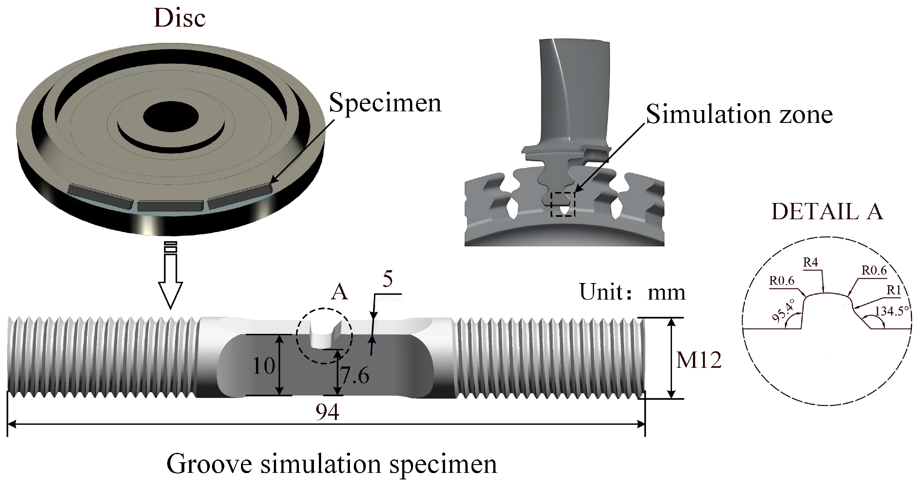
2.1. Materials

The material employed in this study is the domestically developed new third-generation powder-based high-temperature alloy FGH4099, and the corresponding chemical composition (wt. %) is as below: 20 Co, 13 Cr, 4.3 W, 2.9 Mo, 3.6 Al, 3.5 Ti, 1.5 Nb, 0.03 C, and balanced by Ni. The alloy was manufactured using a combination of hot isostatic pressing and isothermal forging. The 0.2% offset yield strength and ultimate tensile strength of the alloy at 500 °C and 700 °C are listed in Table 1. A single-edge notch tensile (SENT) specimen, designed to simulate critical turbine disk locations in aircraft engines, groove, was used to study fatigue crack initiation and small-crack propagation behavior under complex stress states and high temperatures. The shape and dimensions of the specimen are shown in Figure 1. All specimens were precisely machined from a single disk along the circumferential direction, ensuring consistent material properties and eliminating orientation-based variations. To further control experimental conditions, a careful surface preparation process was implemented. The notched surfaces were initially polished with progressively finer abrasive papers, followed by a final polish using a wool wheel. This procedure produced a smooth, uniform surface finish, optimized for reliable fatigue testing.

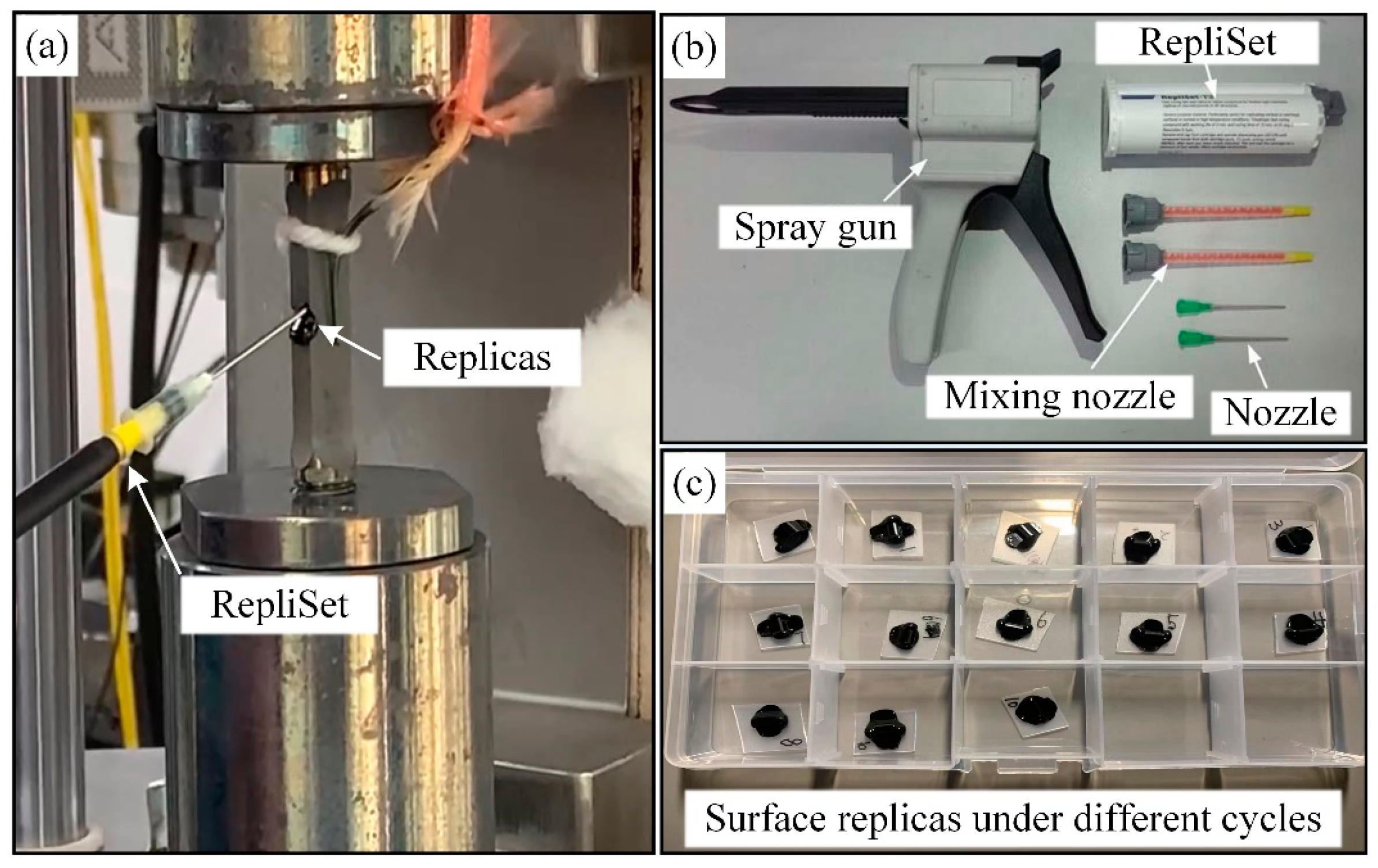
2.2. Experimental Procedure

Fatigue testing was carried out on an Instron 8801 servo-hydraulic testing machine at temperatures of 500 °C and 700 °C. A triangular waveform was employed for loading at a frequency of 10 Hz, using stress ratios (R) of 0.05 and 0.5. The tests were conducted on two specimens at 500 °C, with specimen ID A-1 and A-2; four specimens were tested at 700 °C, with specimen numbers ID B-1, B-2, B-3, and B-4. Heating was achieved with a resistive furnace, maintaining the temperature in the gauge section within ±3 °C. Tests were periodically interrupted at predetermined cycle intervals, based on the fatigue life obtained in uninterrupted fatigue tests. The number of cycles per intervals varied according to the test condition and the expected cyclic life to make sure that about 10–20 replicas were available for each fatigue test. Upon cooling to room temperature, a static tensile load corresponding to 80% of the maximum cyclic stress (σmax) was applied, and the notch was replicated for crack length measurement. Crack monitoring continued until specimen fracture.
The observation of small fatigue crack propagation behaviors typically relies on two primary methods: in situ scanning electron microscopy (SEM) and surface replication. In situ SEM utilizes a high-resolution microscope to continuously monitor the propagation of small cracks under applied test loads. However, this technique is often constrained by experimental limitations, such as the requirement for lower load levels and reduced specimen dimensions. Additionally, in situ SEM typically commonly focuses on the width surface of the specimen, rather than the thickness surface containing the notch. This makes it challenging to accurately monitor small-crack initiation and early propagation in simulation specimens. Therefore, surface replication using RepliSet (Struers Co., Ltd., Shanghai, China), a two-part silicone-rubber compound, was selected in this study. The effectiveness of the surface replication method using RepliSet has been confirmed by extensive research [19,20,21], and detailed procedures are shown in Figure 2. Surface replicas were examined and measured using optical microscopy (OM). The fatigue crack growth rate was determined using a two-point secant method for the replicas recorded. Crack length was defined as the projected length perpendicular to the loading axis. After the fatigue test, fracture surfaces were analyzed using a Hitachi S-3400N scanning electron microscope (Tokyo, Japan).

3. Results

3.1. Fatigue Life

Table 2 and Figure 3 display fatigue life, the proportion of fatigue crack initiation life, and the proportion of life extending to First Engineering Crack size under different temperature and stress ratio conditions. Here, Nf is the total number of cycles until failure; Nini is the number of cycles at which the crack was first observed; cini is the surface crack length at which the crack was first observed; Nc is the number of cycles when the surface crack reaches a First Engineering Crack size of 0.75 mm [22], which is defined based on an assumed initial surface flaw size during the use of fluorescent or magnetic particle nondestructive testing methods, as outlined in the “Engine Structural Integrity Program (ENSIP)”. In all the tests conducted, the crack initiation life proportion (Nini/Nf) of the groove simulation specimens is approximately 54%, and the proportion of life extending to First Engineering Crack size (Nc/Nf) is about 87%. Evidently, for groove simulation specimens, crack initiation and small-crack propagation life constitute the dominant portion of the fatigue life.
Under varying stress ratios, the Nini/Nf ratio decreases with increasing test temperature. For specimen A-1 and B-2 with the same stress ratio (R = 0.05), when the test temperature rises from 500 °C to 700 °C, although the mean stress decreases from 367.5 MPa to 315 MPa, the Nini/Nf ratio decreases from 50% to 43%. A similar phenomenon occurs in the experimental results at R = 0.5. For specimen A-2 and B-4, with the mean stress dropping from 750 MPa to 675 MPa and the temperature rising from 500 °C to 700 °C, the Nini/Nf ratio decreases from 74% to 48%. It indicates that the rise in temperature has a more substantial impact on the fatigue crack initiation life proportion compared to mean stress, with the effect becoming more pronounced as the stress ratio increases. In contrast, the temperature and stress ratio have a relatively small impact on the Nc/Nf ratio. For example, when the mean stress decreases from 750 MPa to 675 MPa and the temperature increases from 500 °C to 700 °C, the Nc/Nf ratio of specimen A-2 and B-4 remains essentially unchanged. Additionally, the life spent on crack propagation from First Engineering Crack size to specimen fracture constitutes about 10% to 20% of the total life, meaning the remaining life after First Engineering Crack is limited for the groove simulation specimens.

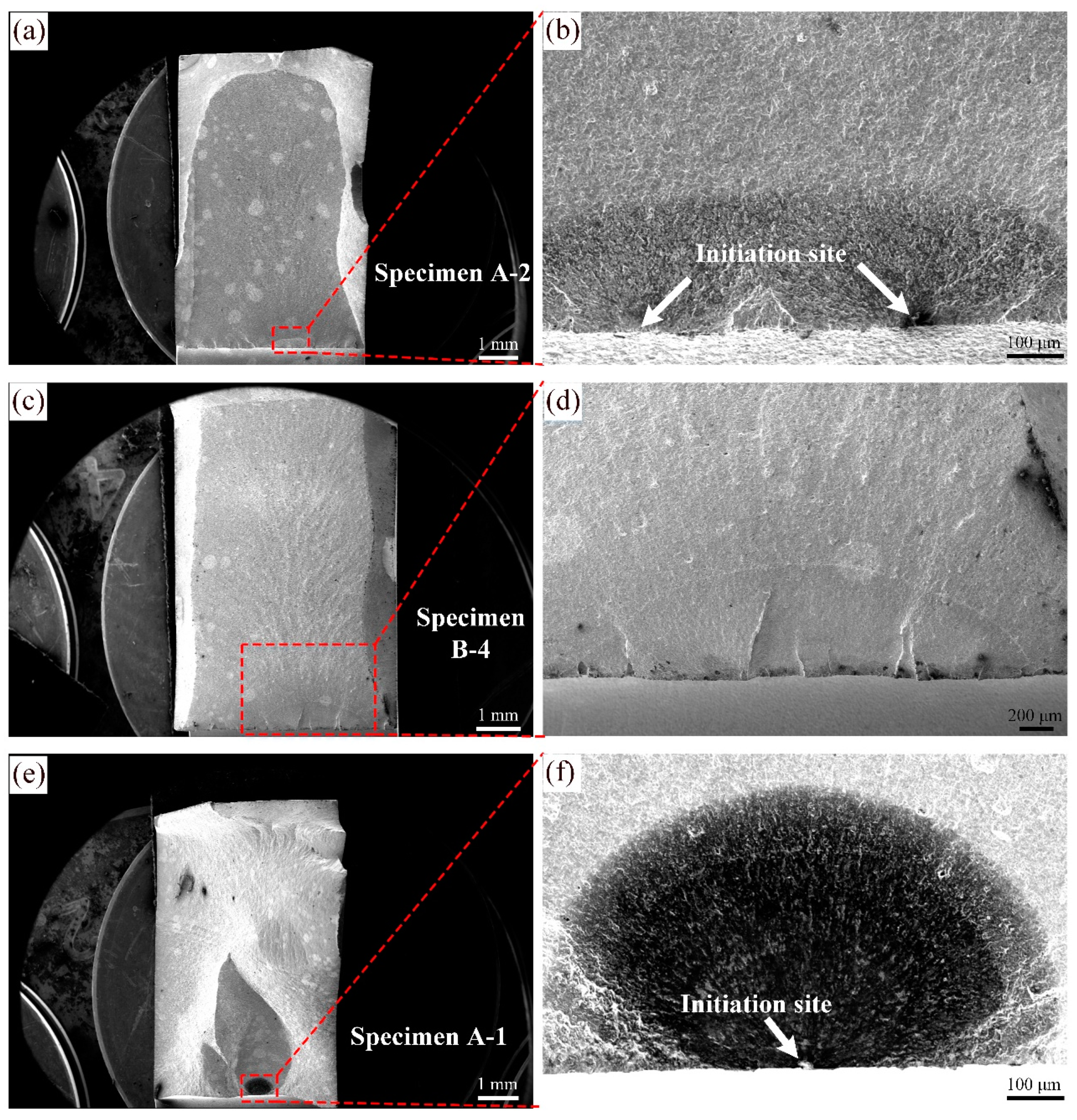
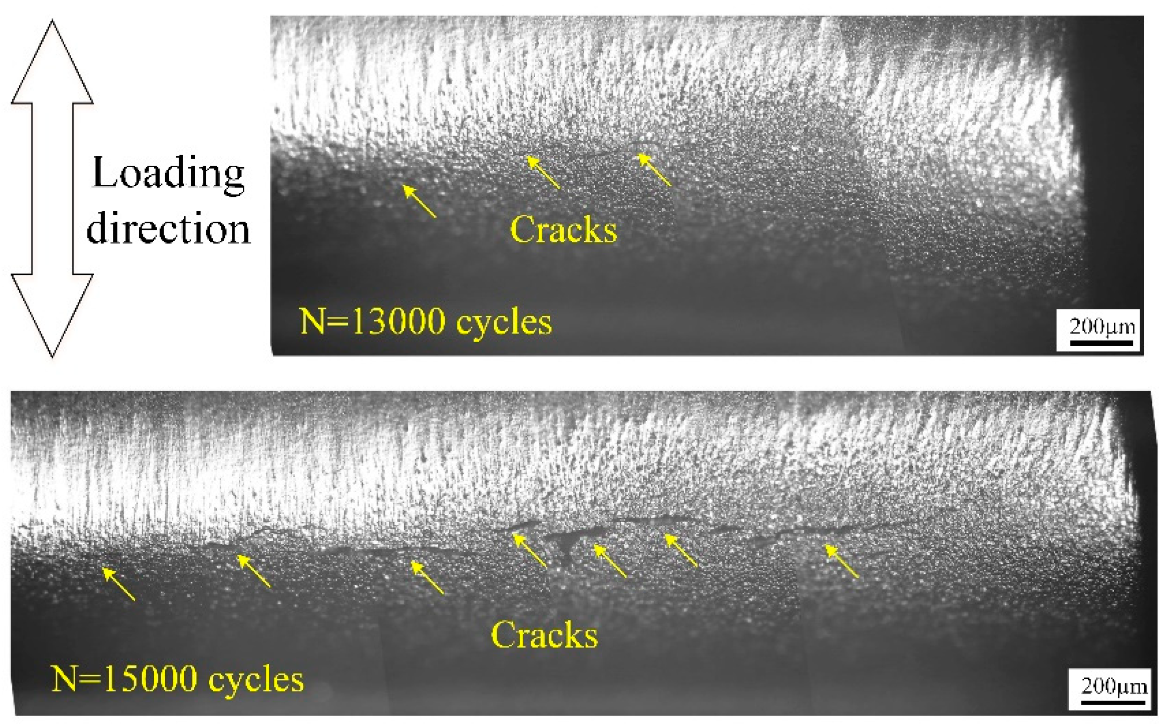
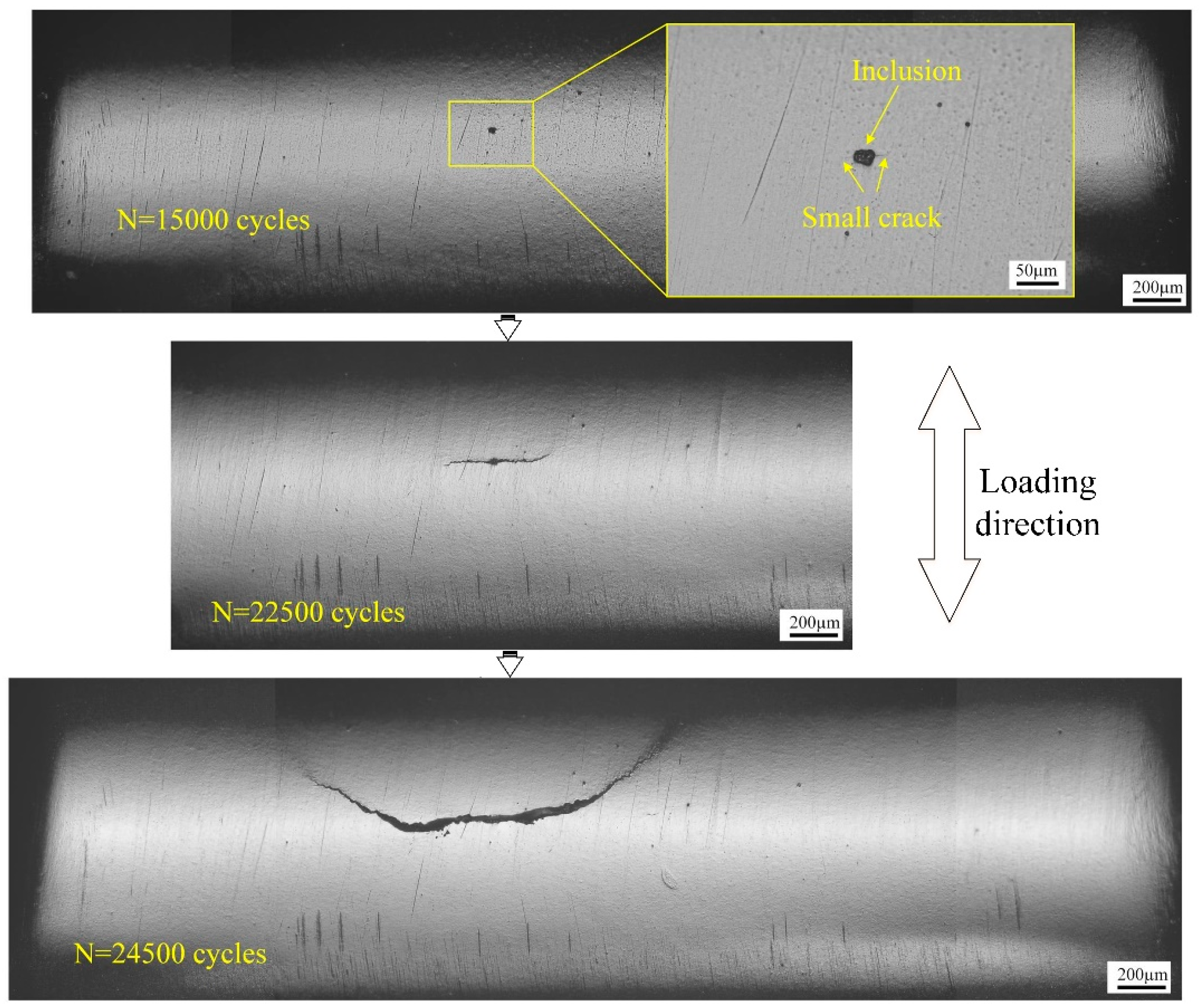
3.2. Crack Initiation

Figure 4 illustrates the main crack initiation locations of the groove simulation specimens by examining the macroscopic fracture features. The crack initiation locations of most specimens were at the notch fillet, such as specimen A-2, B-1, B-2, B-3, and B-4, and only specimen A-1 occurred at the notch root. Furthermore, through a SEM fractographic analysis, the initiation sites of specimens with fatal cracks at the notch fillet were observed to appear consistently at the specimen surface, as shown in Figure 5a–d. This failure mode from surface is usually perceived as an oxidation-assisted fatigue crack initiation, and occurs in slip bands induced by a combination of high stresses and oxidation [10,23]. As shown in Figure 6, multi-site crack initiations were detected on the surface replicas of specimen B-4, which is essentially the same as the fatigue crack initiation characteristics observed in most powder metallurgy nickel-based superalloys [8,9,11,24]. However, for the specimen with crack initiation at the notch root, the initiation mode is characterized by a single crack initiation. Figure 7 presents the surface replicas as a function of cycles for specimen A-1. The initial crack initiated at the boundary between the inclusion and the matrix on the notch surface. It is evident that the presence of surface inclusions is the cause of the change in crack initiation locations.

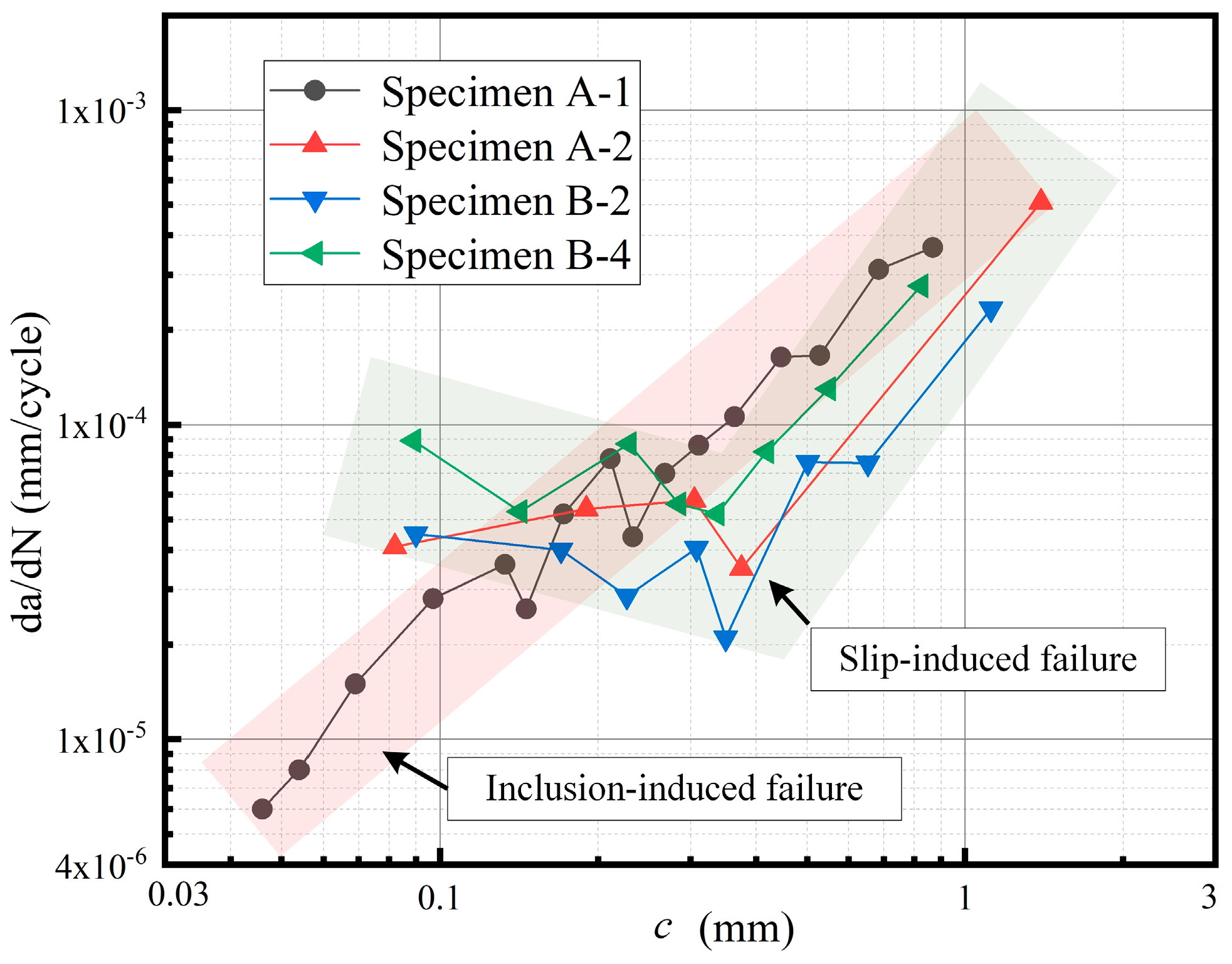
3.3. Crack Propagation

As shown in Figure 4 and Figure 5, the groove simulation specimens with different crack initiation locations show distinct fracture paths. For specimens with crack initiation located at the notch fillet, the fracture surfaces are flat and the transient fracture zone constitutes only a small fraction of the total fracture surface. However, the specimen with crack initiation at the notch root exhibited several fracture planes oriented in different directions. As shown in Figure 7, the crack initially propagated perpendicular to the loading direction, and when the crack length reaches approximately 0.8 mm, the direction of propagation deflected from the initial direction.
Figure 8 displays the fatigue crack growth rates, dc/dN, against the crack lengths, c, for the main fatigue cracks under different test temperatures and stress ratios. The secant method is used to calculate the crack growth rate:
d c d N = c N = c i + 1 c i N i + 1 N i
where Δc and ΔN are the crack growth increment and cyclic interval, respectively, and ci is the surface crack length at Ni cycles. The results indicate noticeable fluctuations in crack growth rates during the early stages of fatigue crack growth. With the same stress, the crack propagation rate increases significantly as the temperature rises. Moreover, an interesting observation is that the trend of crack propagation rate has changed significantly due to the shift in the crack initiation position. The crack growth rate curve of the specimens with crack initiation located at the notch fillet has a turning point, which divides the curve into two stages. On the early crack growth stage, the crack growth rate exhibits significant fluctuations, even showing a gradual decrease. Once the crack reaches a certain crack length, the crack growth rate increases markedly and stably. This phenomenon is essentially the same as the small-crack growth behavior observed in most nickel-based superalloys [2,5,8,9,11,25]. However, for specimens with crack initiation at the notch root, the turning point in the crack growth rate curve is not prominent. This outcome may be attributed to variations in the early fatigue crack propagation behaviors influenced by crack initiation modes, which will be analyzed in detail in subsequent sections.

4. Discussion

4.1. Competing Crack Initiation Modes

The fracture features in Figure 4 exhibit a failure location transition for the groove simulation specimens tested in the temperature of 500 °C and 700 °C, indicating a competing crack initiation modes. Previous studies [11,12,25,26] indicate that the crack initiation in notched fatigue specimens typically occurs at the notch root, where is the location of the maximum normal stress along the load direction. However, the crack initiation sites located at the notch fillet are observed in Figure 4 for the majority of specimens. It is important to note that the normal stress is not the primary factor inducing fatigue crack initiation. To further investigate the stress state at the notch, an elastoplastic finite element analysis was conducted on the groove simulation specimens. The multilinear isotropic hardening mode is used together with the linear elastic mode to achieve an elastoplastic finite element analysis. Figure 9 illustrates the normal stress and maximum principal stress contours of the groove simulation specimens in the temperature of 500 °C and 700 °C. The maximum normal stress appears at the notch root, while the maximum value of the maximum principal stress appears at the position approaching to the notch fillet side. Compared to the observation in Figure 4, the position of the maximum principal stress peak is much closer to the observed crack initiation location in the simulation specimens. This confirms that the effect of principal stress is likely a dominant factor in fatigue failure for the complex notched components.
In addition, the inclusions also affect the fatigue crack initiation behavior in P/M superalloys. As shown in Figure 5f and Figure 6, the abnormal initiation location is caused by the failures occurring from surface inclusions. The P/M superalloys exhibit a strong sensitivity to surface inclusions [27,28]. The higher stress concentrations at the corners of inclusions are more pronounced, resulting in elevated local shear strains. This leads to an increase in dislocation densities, creating preferred sites for cracks to initiate. Additionally, the oxidation effects in high-temperature testing combined with the increase in local stresses further promote crack initiation at the surface [28]. Conversely, for the specimens without surface inclusions, the oxidation-assisted slip mechanisms has become the primary mechanism for sample fracture failure, which is influenced by the local stress state [29]. Therefore, in components with surface defects, the crack initiation site is mainly determined by the location of the defect, while for defect-free components, principal stress plays a crucial role.

4.2. Effect of Initiation Modes on Crack Growth Behavior

The small-crack growth rates plotted against the crack lengths in Figure 7 display two distinct variation patterns. For most simulation specimens, the crack growth data demonstrated a typical small-crack behavior, a turning point in the crack growth rate curves. The initial crack growth rate exhibited a fluctuating and progressively decreasing trend. When the crack reaches a certain crack length, the fluctuation disappears, and the crack growth rate increases with increasing crack size, which is consistent with a typical Paris regime behavior. Conversely, for a few samples, such as specimen A-1, the transition between the small-crack growth stage and long crack growth stage disappeared in the crack growth rate curves. This observation might be attributed to changes in the early fatigue crack propagation behaviors because of the crack initiation modes.
The slower growth of small cracks in the notch root is generally considered to be due to crack closure, a phenomenon resulting from the notch plasticity and the crack tip plasticity [30,31]. However, at elevated temperatures, fatigue tests have shown that oxidation embrittlement can accelerate crack propagation, potentially counteracting the effects of crack closure [32]. This suggests that other factors contribute to the observed reduction in small-crack growth rates. The above analysis indicates that the simulation specimens with a transition in crack growth rate curves presented multi-site crack initiations. These cracks did not grow uniformly, and not all became critical. Some cracks encountered resistance to propagation, potentially from grain boundaries or inclusions, leading to slow growth or becoming non-propagating cracks. Instead of contributing to final failure, these smaller cracks can also delay the growth of the main crack, possibly through shielding effects [11]. Upon reaching a critical size, the small cracks exhibited a rapid transition to fast growth and merged into a single, dominant crack along the notch, ultimately causing specimen fracture. As a result, the overall crack growth rate initially decreases, then increases again. In contrast, for specimens where cracks were initiated at an inclusion, the phenomenon of multiple crack interaction and coalescence is absent, as the initiation is mainly from a single source. Although there is a decrease in crack growth rate due to grain boundary resistance during propagation, the crack growth rate increases as the crack length increases.

5. Conclusions

In this work, the fatigue crack initiation and propagation behavior characterizing groove simulation specimens of FGH4099 superalloy were investigated. The main conclusions of the study are summarized as follows:
(1)
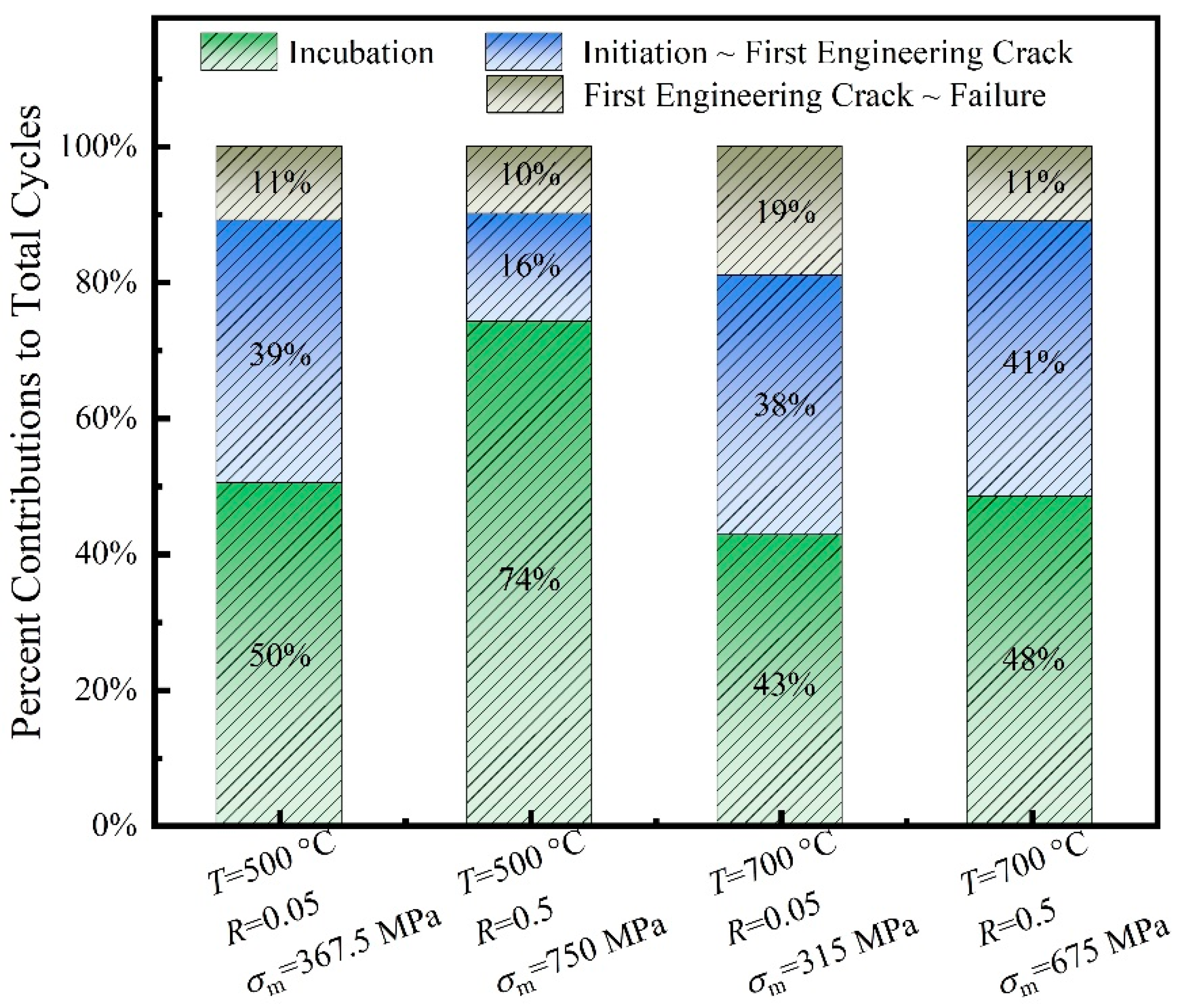
For groove simulation specimens, temperature increases significantly affect the proportion of fatigue crack initiation life, but have less impact on the time it takes for cracks to grow to First Engineering Crack size. When the temperature increases from 500 °C to 700 °C, the crack initiation life proportion decreases from around 50–75% to 40–50%, while the life ratio for cracks reaching First Engineering Crack size remains relatively constant, at about 81–90%.
(2)
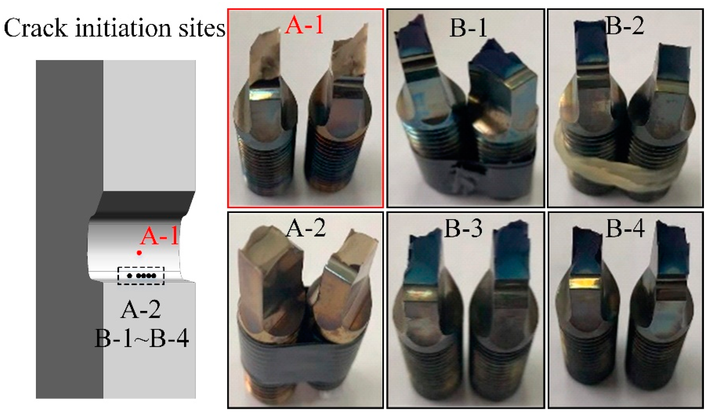
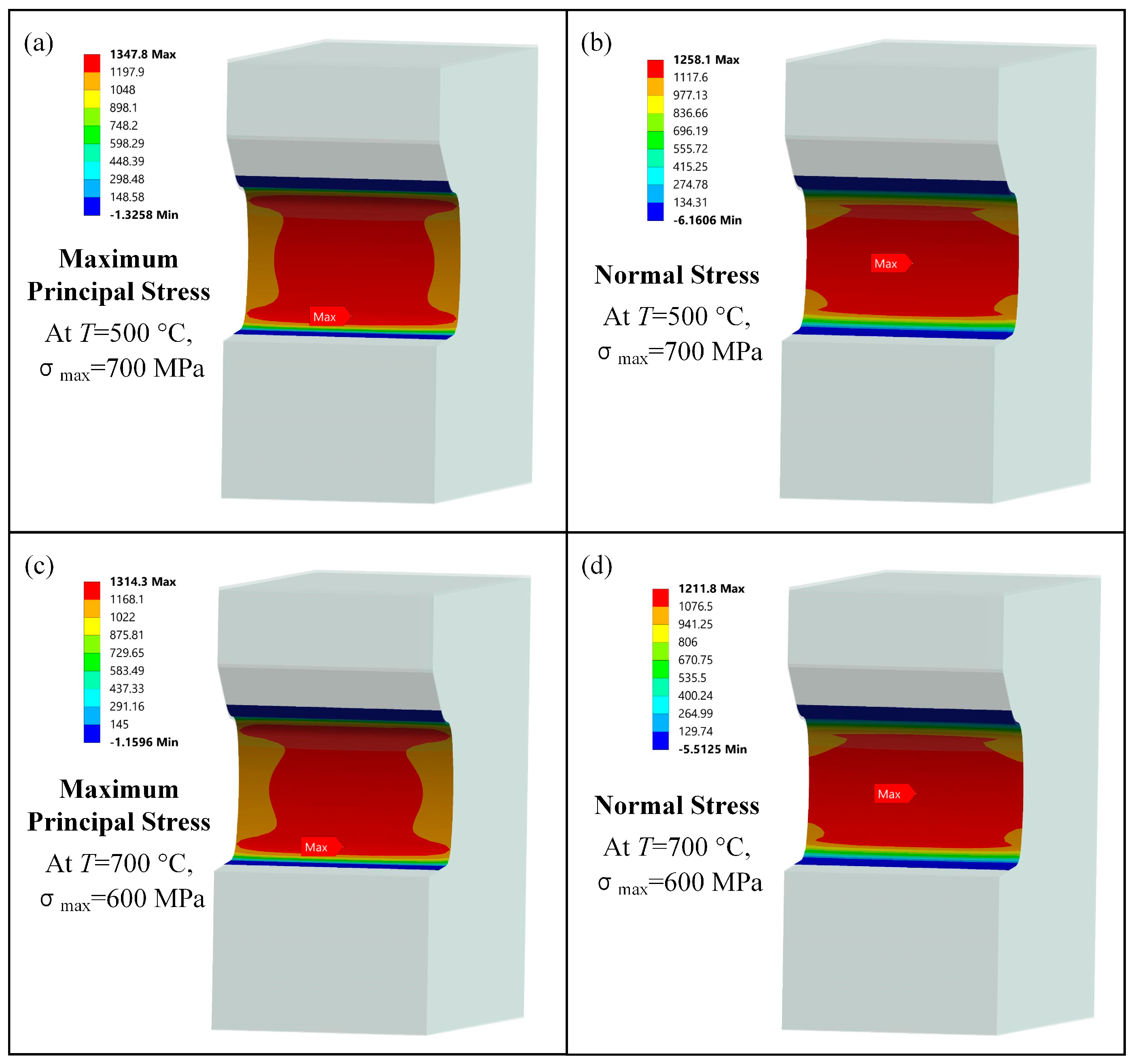
The primary factors governing fatigue crack initiation sites in simulation specimens are the maximum principal stress and surface inclusions. The fatigue cracks tend to originate at the location of maximum principal stress, rather than the location of maximum normal stress at the notch root. Furthermore, the presence of surface inclusions is also a significant factor in determining where cracks initiate.
(3)
The main cause of the reduction in small-crack growth rate as crack length increases is the shielding by the cracks around the main crack. As cracks grow to a certain size, the shielding effect weakens, while the crack coalescence becomes more pronounced, resulting in a rapid acceleration of the crack growth rate.
These findings collectively advance the understanding of high-temperature fatigue mechanisms, crack initiation criteria, and multi-crack interactions. They provide scientific support for advancements in the life assessment and damage tolerance design of turbine disks.

Author Contributions

Conceptualization, Z.Z. and X.H.; methodology, Z.Z.; software, Z.Z. and X.H.; validation, Z.Z., X.H. and Z.G.; formal analysis, Z.Z.; investigation, Z.Z. and Z.G.; resources, X.H.; data curation, Z.Z.; writing—original draft preparation, Z.Z.; writing—review and editing, Z.Z.; visualization, Z.Z.; supervision, X.H.; project administration, Z.Z. and X.H.; funding acquisition, Z.Z. and X.H. All authors have read and agreed to the published version of the manuscript.

Funding

This research was funded by the Natural Science Foundation of the Jiangsu Higher Education Institutions of China, grant number 23KJB460026.

Data Availability Statement

The original contributions presented in this study are included in the article. Further inquiries can be directed to the corresponding author.

Conflicts of Interest

Author Zhiwei Guo was employed by AECC Shenyang Engine Research Institute. The remaining authors declare that the research was conducted in the absence of any commercial or financial relationships that could be construed as a potential conflict of interest.

References

  1. Sreenu, B.; Sarkar, R.; Kumar, S.S.S.; Chatterjee, S.; Rao, G.A. Microstructure and mechanical behaviour of an advanced powder metallurgy nickel base superalloy processed through hot isostatic pressing route for aerospace applications. Mater. Sci. Eng. A 2020, 797, 140254. [Google Scholar] [CrossRef]
  2. Zhang, L.; Wang, Y.Z.; Yu, Z.W.; Jiang, R.; Baxevanakis, K.P.; Roy, A.; Zhao, L.G.; Tian, G.F.; Song, Y.D. Thermo-mechanical fatigue crack growth in a nickel-based powder metallurgy superalloy. Int. J. Fatigue 2024, 186, 108413. [Google Scholar] [CrossRef]
  3. Jiang, J.; Yang, J.; Zhang, T.; Zou, J.; Wang, Y.; Dunne, F.P.E.; Britton, T.B. Microstructurally sensitive crack nucleation around inclusions in powder metallurgy nickel-based superalloys. Acta Mater. 2016, 117, 333–344. [Google Scholar] [CrossRef]
  4. Shi, Y.; Yang, X.G.; Yang, D.D.; Shi, D.Q.; Miao, G.L.; Wang, Z.F. Evaluation of the influence of surface crack-like defects on fatigue life for a P/M nickel-based superalloy FGH96. Int. J. Fatigue 2020, 137, 105639. [Google Scholar] [CrossRef]
  5. Hu, D.Y.; Wang, T.; Ma, Q.H.; Liu, X.; Shang, L.H.; Li, D.; Pan, J.C.; Wang, R.Q. Effect of inclusions on low cycle fatigue lifetime in a powder metallurgy nickel-based superalloy FGH96. Int. J. Fatigue 2019, 118, 237–248. [Google Scholar] [CrossRef]
  6. Xu, C.; Yao, Z.H.; Dong, J.X.; Jiang, Y.J. Mechanism of high-temperature oxidation effects in fatigue crack propagation and fracture mode for FGH97 superalloy. Rare Met. 2019, 38, 642–652. [Google Scholar] [CrossRef]
  7. Li, Z.; He, Y.; Xu, G.; Shi, D.; Yang, G. A fatigue life estimation approach considering the effect of geometry and stress sensitivity. Theor. Appl. Fract. Mech. 2021, 112, 102915. [Google Scholar] [CrossRef]
  8. Bache, M.R.; Hanlon, J.O.; Child, D.J.; Hardy, M.C. High temperature fatigue behaviour in an advanced nickel based superalloy: The effects of oxidation and stress relaxation at notches. Theor. Appl. Fract. Mech. 2016, 84, 64–67. [Google Scholar] [CrossRef]
  9. Telesman, J.; Gabb, T.P.; Ghosn, L.J.; Gayda, J. Effect of notches on creep–fatigue behavior of a P/M nickel-based superalloy. Int. J. Fatigue 2016, 87, 311–325. [Google Scholar] [CrossRef]
  10. Stinville, J.C.; Martin, E.; Karadge, M.; Ismonov, S.; Soare, M.; Hanlon, T.; Sundaram, S.; Echlin, M.P.; Callahan, P.G.; Lenthe, W.C.; et al. Fatigue deformation in a polycrystalline nickel base superalloy at intermediate and high temperature: Competing failure modes. Acta Mater. 2018, 152, 16–33. [Google Scholar]
  11. Connolley, T.; Reed, P.; Starink, J.M. Short crack initiation and growth at 600 °C in notched specimens of Inconel 718. Mater. Sci. Eng. A 2003, 340, 139–154. [Google Scholar]
  12. Deng, G.J.; Tu, S.T.; Zhang, X.C.; Wang, Q.Q.; Qin, C.H. Grain size effect on the small fatigue crack initiation and growth mechanisms of nickel-based superalloy GH4169. Eng. Fract. Mech. 2015, 134, 433–450. [Google Scholar]
  13. Deng, G.J.; Tu, S.T.; Zhang, X.C.; Wang, J.; Zhang, C.C.; Qian, X.Y.; Wang, Y.N. Small fatigue crack initiation and growth mechanisms of nickel-based superalloy GH4169 at 650 °C in air. Eng. Fract. Mech. 2016, 153, 35–49. [Google Scholar]
  14. Kevinsanny; Okazaki, S.; Takakuwa, O.; Ogawa, Y.; Okita, K.; Funakoshi, Y.; Yamabe, J.; Matsuoka, S.; Matsunaga, H. Effect of defects on the fatigue limit of Ni-based superalloy 718 with different grain sizes. Fatigue Fract. Eng. Mater. Struct. 2019, 42, 1203–1213. [Google Scholar]
  15. Maenosono, A.; Koyama, M.; Tanaka, Y.; Rid, S.; Wang, Q.H. Crystallographic selection rule for the propagation mode of microstructurally small fatigue crack in a laminated Ti-6Al-4V alloy: Roles of basal and pyramidal slips. Int. J. Fatigue 2019, 128, 105200. [Google Scholar] [CrossRef]
  16. Wang, J.; Wang, R.Z.; Zhang, X.C.; Ye, Y.J.; Cui, Y.; Miura, H.; Tu, S.T. Multi-stage dwell fatigue crack growth behaviors in a nickel-based superalloy at elevated temperature. Eng. Fract. Mech. 2021, 253, 107859. [Google Scholar]
  17. Yang, Q.Z.; Yang, X.G.; Huang, W.Q.; Shi, Y.; Shi, D.Q. Small fatigue crack propagation rate and behaviours in a powder metallurgy superalloy: Role of stress ratio and local microstructure. Int. J. Fatigue 2022, 160, 106861. [Google Scholar]
  18. Pang, H.T.; Reed, P.A.S. Microstructure effects on high temperature fatigue crack initiation and short crack growth in turbine disc nickelbase superalloy udimet 720Li. Mater. Sci. Eng. A 2007, 448, 67–79. [Google Scholar]
  19. Newman, J.A.; Willard, S.A.; Smith, S.W.; Piascik, R.S. Replica-based crack inspection. Eng. Fract. Mech. 2009, 76, 898–910. [Google Scholar]
  20. Jordon, J.B.; Bernard, J.D.; Newman, J.C. Quantifying microstructurally small fatigue crack growth in an aluminum alloy using a silicon-rubber replica method. Int. J. Fatigue 2012, 36, 206–210. [Google Scholar]
  21. Zhu, L.; Wu, Z.R.; Hu, X.T.; Song, Y.D. Investigation of small fatigue crack initiation and growth behaviour of nickel base superalloy GH4169. Fatigue Fract. Eng. Mater. Struct. 2016, 39, 1150–1160. [Google Scholar]
  22. Corran, R.S.J.; Williams, S.J. Lifing methods and safety criteria in aero gas turbines. Eng. Fail. Anal. 2007, 14, 518–528. [Google Scholar] [CrossRef]
  23. Carroll, L.J.; Cabet, C.; CarrollM, C.; Wright, R.N. The development of microstructural damage during high temperature creep-fatigue of a nickel alloy. Int. J. Fatigue 2013, 47, 115–125. [Google Scholar] [CrossRef]
  24. Hu, X.A.; Shi, D.Q.; Yang, X.G. Thermomechanical fatigue experimental study on a notched directionally solidified Ni-base superalloy. Mater. Sci. Eng. A 2016, 674, 451–458. [Google Scholar]
  25. Sansoz, F.; Brethes, B.; Pineau, A. Propagation of short fatigue cracks from notches in a Ni base superalloy: Experiments and modelling. Fatigue Fract. Eng. Mater. Struct. 2022, 25, 41–53. [Google Scholar] [CrossRef]
  26. Pang, H.T.; Reed, P.A.S. Fatigue crack initiation and short crack growth in nickel-base turbine disc alloys—The effects of microstructure and operating parameters. Int. J. Fatigue 2003, 25, 1089–1099. [Google Scholar]
  27. Caton, M.J.; Jha, S.K. Small fatigue crack growth and failure mode transitions in a Ni-base superalloy at elevated temperature. , Int. J. Fatigue 2010, 32, 1461–1472. [Google Scholar] [CrossRef]
  28. Telesmana, J.; Gabba, T.P.; Kantzosb, P.T.; Bonacusea, P.J.; Barriec, R.L.; Kantzos, C.A. Effect of a large population of seeded alumina inclusions on crack initiation and small crack fatigue crack growth in Udimet 720 nickel-base disk superalloy. Int. J. Fatigue 2021, 142, 105953. [Google Scholar] [CrossRef]
  29. Pineau, A.; Antolovich, S.D. High temperature fatigue of nickel-base superalloys—A review with special emphasis on deformation modes and oxidation. Eng. Fail. Anal. 2009, 16, 2668–2697. [Google Scholar]
  30. Shin, C.S.; Smith, R.A. Fatigue crack growth at stress concentrations–the role of notch plasticity and crack closure. Eng. Fract. Mech. 1988, 29, 201–315. [Google Scholar] [CrossRef]
  31. Yuan, S.H.; Wang, Y.R.; Wei, D.S. Experimental investigation on low cycle fatigue and fracture behavior of a notched Ni-based superalloy at elevated temperature. Fatigue Fract. Eng. Mater. Struct. 2014, 37, 1002–1012. [Google Scholar] [CrossRef]
  32. Jiang, R.; Song, Y.D.; Reed, P.A. Fatigue crack growth mechanisms in powder metallurgy Ni-based superalloys-A review. Int. J. Fatigue 2020, 141, 105887. [Google Scholar] [CrossRef]
Figure 1. Orientation of specimens extracted from disk and geometric dimension of simulation specimen.
Metals 15 00384 g001
Figure 2. Surface replication procedure: (a) surface replication operation, (b) RepliSet system, and (c) surface replicas.
Metals 15 00384 g002
Figure 3. Proportion of fatigue crack initiation life, and proportion of life extending to First Engineering Crack size under different temperature and stress ratio conditions.
Metals 15 00384 g003
Figure 4. Diagrammatic drawing of main crack initiation locations in the notch and macroscopic fracture.
Metals 15 00384 g004
Figure 5. SEM images of surface morphologies. (a,b) specimen A-2, (c,d) specimen B-4, and (e,f) specimen A-1.
Metals 15 00384 g005
Figure 6. Surface replicas for specimen B-4.
Metals 15 00384 g006
Figure 7. Surface replicas for specimen A-1.
Metals 15 00384 g007
Figure 8. Variations in crack lengths along the number of cycles for simulation specimens.
Metals 15 00384 g008
Figure 9. Maximum principal stress and normal stress at the notches for simulation specimen: (a,b) at T = 500 °C, σmax = 700 MPa, and (c,d) at T = 700 °C, σmax = 600 MPa.
Metals 15 00384 g009
Table 1. The 0.2% offset yield strength and ultimate tensile strength of the alloy.
Temperature [°C]Yield Strength [MPa]Ultimate Tensile Strength [MPa]
50011291591
70011061276
Table 2. Fatigue life, crack initiation life, and the proportion of total life under different temperature and stress ratio conditions.
Specimen IDT [°C]σmax [MPa]RNfNinicini [μm]Nini/NfNcNc/NfTest Conditions
A-15007000.0525,85313,0004050%23,01989%Replica
A-250010000.540,43830,0008274%36,42490%Replica
B-17006000.0522,265-----Non-replica
B-27006000.0532,83914,0009043%26,59981%Replica
B-370010000.58650-----Non-replica
B-47009000.516,53780008948%14,70189%Replica
Disclaimer/Publisher’s Note: The statements, opinions and data contained in all publications are solely those of the individual author(s) and contributor(s) and not of MDPI and/or the editor(s). MDPI and/or the editor(s) disclaim responsibility for any injury to people or property resulting from any ideas, methods, instructions or products referred to in the content.

