Article

Comparative Analysis of the Microstructure and Tribological Behaviors of Ni-, Fe-, and Co-Based Plasma Cladding Coatings

1
National United Engineering Laboratory for Advanced Bearing Tribology, Henan University of Science and Technology, Luoyang 471023, China
2
Collaborative Innovation Center of Nonferrous Metals, Henan University of Science and Technology, Luoyang 471023, China
*
Author to whom correspondence should be addressed.
Metals 2025, 15(4), 344; https://doi.org/10.3390/met15040344
Submission received: 16 February 2025 / Revised: 18 March 2025 / Accepted: 20 March 2025 / Published: 21 March 2025

Abstract

Nickel-, iron-, and cobalt-based alloy coatings were fabricated on the surface of U75V steel utilizing plasma cladding technology. This study investigates the microstructure, mechanical properties, and tribological performance of the coatings. The findings reveal that the microstructure of the coatings predominantly consists of dendritic and eutectic structures. The surface microstructure exhibited a dense, continuous, and uniform morphology. Following the cladding process, the samples were characterized by residual compressive stress. In comparison to the substrate, the hardness of the Ni-, Fe-, and Co-based coatings increased by 141%, 101%, and 44%, respectively; the wear rates of these coatings decreased by 36.6%, 22.1%, and 11.7%, respectively. The wear mechanisms of the Ni- and Fe-based coatings were predominantly adhesive wear; however, the extent of adhesive wear of the Fe-based coating was more obvious than that of the Ni-based coating. By contrast, the Co-based coating exhibited abrasive wear, which was the most severe among the three types of coatings. Additionally, the Ni-based coating demonstrated the lowest friction coefficient and wear rate, thereby exhibiting superior wear resistance compared to the other two coatings.

1. Introduction

The deterioration of rail materials has become more pronounced due to the increasing construction of railroad tracks and the rise in train traffic, compounded by the trends toward higher speeds and heavier loads in railway transportation [1]. Wear is a critical factor contributing to rail degradation in the early stages, which can directly lead to cracking or fracturing of the rails, thereby posing significant safety risks for trains [2,3,4,5]. Consequently, the enhancement of rail material properties has emerged as a focal point of research [6,7].
Meng et al. [8] used laser cladding technology to fabricate various coatings on the surface of rails. The data indicated that the cladding significantly reduced the wear rate of the rail compared to untreated specimens. Lewis et al. [9] utilized laser cladding technology to melt four distinct types of powders onto the surface of R260 rails. The results demonstrated that, under both dry and wet conditions, the wear performance of the cobalt-based alloy coating met the established criteria. Similarly, Meng et al. [10] applied laser cladding technology to produce a coating on the surface of rails. The findings revealed that the post-laser-induced heat treatment (LIHC) markedly enhanced the rails’ hardness, strength, and toughness, while preserving the integrity of their mechanical properties and heat-affected zone (HAZ) structure. Yang et al. [11] implemented laser cladding technology to develop a Fe-based coating on U75V steel, with results indicating that the coating effectively mitigated rail wear and rolling contact fatigue. Xie et al. [12] also employed laser cladding technology to apply coatings on the surfaces of damaged rails. Their findings showed that the wear rates of rails coated with five different cladding materials (304, 314, 2Cr13, 316L, and 434L) were significantly lower than those of uncoated rails. While laser cladding technology can enhance the wear resistance and other properties of materials, it also presents challenges, such as high equipment costs, inconsistent cladding quality, low cladding powder utilization, and suboptimal surface quality of the coatings. The potential for large-scale material substitution and waste reduction exists if alternative methods are developed to address these challenges and improve coating performance.
Plasma cladding technology is recognized as an effective method for surface strengthening. It offers many advantages, including strong metal bonding, high operational efficiency, ease of use [13,14,15,16], and cost-effectiveness [17,18]. Nevertheless, to date, there has been a lack of systematic investigation into the feasibility and tribological properties of nickel-based, iron-based, and cobalt-based alloy coatings applied to U75V rails via plasma cladding. U75V steel is a widely utilized high-strength rail steel known for its exceptional wear resistance and fatigue endurance-qualities that are particularly advantageous in heavy-haul railway applications. The choice of Ni-based, Fe-based, and Co-based alloy powders as cladding materials stems from their superior wear resistance characteristics. Nickel-based alloys are renowned not only for their excellent wear resistance but for their commendable oxidation resistance [19], while Fe-based alloys are celebrated for their high hardness coupled with relatively low costs that further enhance wear performance [20], and Co-based alloys exhibit outstanding high-temperature capabilities and fatigue resilience while demonstrating remarkable wear resistance under complex operating conditions [21]. Comparative studies can yield a more comprehensive technical solution for the surface enhancement of railway tracks.
This study employs the plasma cladding technique to create various alloy coatings (Ni-, Fe-, and Co-based) on the surface of U75V steel. The samples undergo wear and friction testing both prior to and following the cladding process. The tribological characteristics and microstructure of the coatings are examined, providing reference data for the future application of plasma cladding technology in rail systems.

2. Experimental

2.1. Materials and Cladding Process

The base material, obtained from the upper section of the U75V rail (Pangang Group Company Limited, Panzhihua, China), measures 120 mm × 55 mm × 30 mm. The substrate surface was subsequently pre-treated to achieve a surface roughness of 0.5 μm. The chemical composition of the base material is detailed in Table 1. The plasma cladding powders consist of Ni-, Fe-, and Co-based alloy powders, all manufactured by Tianjin Cast Gold Technology and Development Corporation Ltd. (Tianjin, China). The individual chemical compositions of these powders are presented in Table 2.
The morphology of the three alloy powders is depicted in Figure 1, consists of spherical or rod-like particles with smooth surfaces. The particle size distribution for the Ni-based powder ranges from 100 to 150 μm, for the Fe-based powder from 100 to 140 μm, and for the Co-based powder from 80 to 140 μm. The regular spherical structure not only reduces friction among the particles but enhances the fluidity of the powder, thereby improving the quality of the coating [22].
Prior to testing, the surface of the matrix material was subjected to sanding and ultrasonic cleaning for 500 s in anhydrous ethanol and acetone. The alloy powder was subsequently dried for three hours at 110 °C in a vacuum drying box. The PTA-400E4-ST powder plasma spray welding apparatus (Wuhan Research Institute of Materials Protection Co., Ltd., Wuhan, China) was utilized to apply coatings to the surface of the sample using dried Ni-based, Fe-based, and Co-based alloy powders, respectively.
The parameters for the cladding process were established based on the previous experimental trials conducted by our research group [23,24]. The principal process parameters are presented in Table 3, while the supplementary parameters include a nozzle height of 11 mm, a swing speed of 1100 mm·min⁻1, a swing width of 12 mm, a plasma gas flow rate of 300 L/h, a powder feeding gas flow rate of 300 L/h, and a shielding gas flow rate of 800 L/h, with high-purity argon (99.99%) utilized as the shielding gas.

2.2. Microstructure Examination

The cladding samples were bisected along the central line of the welding layer, and subsequent experimental samples were derived through wire cutting in the vertical direction of the welding layer. Following sequential polishing, each sample underwent chemical etching for 30 s utilizing an aqua regia solution composed of three volumes of concentrated hydrochloric acid and one volume of strong nitric acid. The microstructures of the coated surfaces and the bonding zones were analyzed using a metallographic microscope, an energy dispersive spectrometer (EDS, Quanta 600, Thermo Fisher Scientific, Waltham, MA, USA), and a scanning electron microscope (SEM, JSM-IT100, JEOL Ltd., Tokyo, Japan). The phase composition of the three coatings was investigated utilizing an X-ray diffractometer (XRD, D8-advanced, Bruker AXS, Bruker, Karlsruhe, Germany) with a scanning angle range of 40° to 90°. A nickel beta (Niβ) filter was employed to eliminate Cu Kβ radiation, with a step size of 0.02°.

2.3. Mechanical Properties Test

The surface and cross-sectional hardness of the coating and substrate samples were assessed using a microhardness tester (HV-1000, Laizhou Huayin Testing Instrument Co., Ltd., Laizhou City, Shandong, China). A load of 500 g was applied with a dwell time of 10 s. Measurements were conducted at 1 mm intervals on the sample surface. The surface hardness was calculated as an average of ten discrete measurement points, which were strategically selected along the central line of the coating surface to mitigate the influence of edge effects and local defects on the results. For the cross-sectional hardness measurement of the coating, readings were taken at 100 μm intervals from the coating to the substrate.
A stress meter (Proto iXRD, Proto Manufacturing Ltd., Windsor, ON, Canada) was employed to quantify the residual stress. The roll fixed swing angle method was selected for measurement purposes. The radiation target utilized was Cr-Kα, β, with an angular range of 9, spanning from −30° to 30°, and a scanning step distance of 0.1°. Given that the instrument is unable to directly measure the residual stress on the coating surface, the residual stress on the coating surface was inferred from the residual stress measurements of the metal on both sides of the weld.

2.4. Friction and Wear Experiment

Friction and wear tests were conducted using a multifunctional friction and wear tester (UMT-2, Center for Tribology Inc., Campbell, CA, USA). The specimens utilized in these tests were uniform in terms of size, shape, and surface roughness. Each experimental set was replicated three times to ensure the accuracy and reliability of the results. Prior to the experiments, both the coating and substrate samples underwent ultrasonic cleaning in anhydrous ethanol for 500 s. The material employed was a GCr15 steel ball with a diameter of Φ6.35 mm (hardness of 745 HV0.5), and the friction mode was established as ball-on-disk contact. The testing conditions encompassed dry friction with a load of 30 N (resulting in a corresponding contact stress of 1959.23 MPa), a reciprocating distance of 6 mm, a reciprocating speed of 5 mm/s, and a duration of 30 min for the reciprocating motion. Consistency was maintained across the specimens in terms of dimensions, shape, and surface roughness, with each test repeated thrice for validation of the experimental data.
Subsequent to the tests, a three-dimensional profiler (NanoFocus, NanoFocus AG, Oberhausen, Germany) was utilized to measure the breadth and depth of the wear scar after the samples had been ultrasonically cleaned and dried with anhydrous ethanol. The microstructure of the wear scar on the sample surface was examined using scanning electron microscopy. Finally, the test results were analyzed to evaluate the wear mechanism of the material.
Utilizing the primary control computer software, the friction and wear tester automatically recorded the friction coefficient. The following formula was employed to calculate the wear rate [25,26,27,28]:
W = L × A F n × v × t
where W is the wear rate mm3/(N m); L is the wear mileage (6 mm); A is the average cross-sectional area of the wear scar measured at six different positions using a three-dimensional profilometer (μm2); Fn is the applied load (N); v is the reciprocating speed (mm/s); t is the wear time (s).

3. Results of the Test

3.1. Microstructure of the Test

The microstructures of the substrate and coating surfaces are illustrated in Figure 2. No visible pores or other structural defects are present, and the coating exhibits a high surface density. As depicted in Figure 2a, the microstructure of the matrix material, U75V steel, is characterized by pearlite, which primarily consists of parallel lamellar ferrite and granular cementite. The microstructure of the Ni-based coating, shown in Figure 2b, is dense and comprises dendrites, equiaxed crystals, and columnar crystals. In Figure 2c, the microstructure of the Fe-based coating is presented, revealing a composition of columnar crystals and a eutectic structure with a slightly larger grain size compared to the Ni-based coating. Figure 2d illustrates the microstructure of the Co-based coating, which is predominantly composed of a eutectic structure; despite its dense surface, the overall grain size is excessively large.
The EDS results for the specified locations in Figure 2 are summarized in Table 4. Area A indicates that the surface of U75V steel is primarily composed of a significant amount of iron (Fe) with a minor presence of carbon (C). Areas B and C reveal that the Ni-based coating surface contains Fe, Ni, C, chromium (Cr), and silicon (Si); specifically, the crystal in Area B exhibits a high concentration of chromium, while the crystal in Area C is rich in nickel. Areas D and E show comparable elemental compositions, with the same types of elements present on the surface of the Fe-based coating. The surface of the Co-based coating, as represented by Areas F and G, contains Fe, Ni, C, Cr, Si, tungsten (W), and cobalt (Co), with a notable concentration of cobalt in the crystal at Area F and a significant presence of chromium between the crystals at Area G. The concentrations of carbon and chromium in Area B are the highest among all markers. The differing elemental content at each marker point may be attributed to the ample heat applied during the plasma cladding process, which creates favorable conditions for element diffusion.
Figure 3 presents the EDS results for the cross-sections of various alloy coatings. The red arrow indicates the scanning position and direction; the upper section represents the substrate, the middle section corresponds to the heat-affected zone, and the lower section depicts the coating. Notably, the cross-section of the samples reveals an absence of pores, cracks, and other defects. As illustrated in Figure 1, the initial microstructure of the powder comprises regular spherical particles, which exhibit exceptional flowability and spreadability. These attributes facilitate a more uniform distribution of the powder during the deposition process. The spherical particles are capable of rapidly achieving thermal equilibrium during melting, resulting in the formation of a stable molten pool that cools and solidifies uniformly. This uniformity is advantageous for the development of dense microstructures characteristic of each coating surface [29,30], as demonstrated in Figure 2. Furthermore, the regular spherical morphology of the initial powder promotes enhanced metallurgical bonding with the substrate during the cladding process.
Figure 3b displays the EDS results for the cross-section of the nickel-based coating. It is observed that, as the scanning distance increases from the substrate to the coating, the concentration of Fe decreases gradually, while the concentrations of Ni and Cr increase progressively. The concentrations of Si and C elements exhibit slight fluctuations. The EDS data for the cross-section of the iron-based coating are presented in Figure 3d. The results indicate significant quantities of Fe and Cr within the coating structure. With increasing scanning distance, the concentrations of C, Ni, and Si exhibit marginal increases, whereas the Cr concentration increases to a certain level before exhibiting variability, and the Fe concentration decreases to a certain level with fluctuations. The EDS data for the cross-section of the cobalt-based coating are shown in Figure 3f. It is apparent that the concentration of Fe progressively declines as the scanning distance increases, while the concentrations of Co and Cr rise to a certain level before varying, and the concentrations of C, Si, and W exhibit slight increases. The migration of metal elements from regions of high concentration to those of low concentration during the plasma cladding process may enhance the metallurgical bonding between the substrate and the coating [31].
The XRD patterns of the four sample groups are illustrated in Figure 4. The Ni-based coating predominantly consists of solid solutions of γ-Ni (PDF # 04-0850), Fe-Ni (PDF # 26-0790), and (Fe, Cr)7C3 (PDF # 05-0720), as depicted in Figure 4a. Furthermore, the presence of Cr7C3 (PDF # 11-0550), CrB2 (PDF # 65-8664), and Cr3C2 (PDF # 35-0804) are also identified within the coatings. The Fe-based coating primarily comprises solid solutions of α-Fe (PDF # 06-0696), Fe-Cr (PDF # 54-0331), and Fe-Ni (PDF # 26-0790), as presented in Figure 4b. Additionally, the Cr7C3 (PDF # 11-0550) and CrB2 (PDF # 65-8664) phases are similarly detected in these coatings. The Co-based coating is largely constituted of solid solutions of γ-Co (PDF # 15-0806) and Cr7C3 (PDF # 11-0550).

3.2. Mechanical Characteristics

The microhardness values for the four sample groups are displayed in Figure 5a. The untreated sample exhibited an average hardness of 339.3 HV0.5. By contrast, the average hardness values for the Ni-, Fe-, and Co-based coatings were recorded at 814.9 HV0.5, 682.7 HV0.5, and 487.5 HV0.5, respectively. The microhardness of the coatings is significantly enhanced following plasma cladding; the change rates in microhardness for the Ni-, Fe-, and Co-based coatings before and after cladding are approximately 141%, 101%, and 44%, respectively. The variation in hardness among the three coatings is closely correlated with the microstructures of the samples. As illustrated in Figure 2, the Ni-based coating features a dense surface with a fine grain size, the Fe-based coating presents an intermediate structure, while the Co-based coating, despite being equiaxed, exhibits a larger overall grain size, which limits the enhancement in hardness [32]. Consequently, the hardness results are presented as shown in Figure 5a.
Figure 5b presents the cross-sectional microhardness profiles of Ni-, Fe-, and Co-based coatings. The coating region exhibits the largest area, with a significant decrease in hardness observed in the heat-affected zone, extending up to the U75V steel substrate. Notably, the overall trend of the three sets of curves remains consistent. The Ni-based coating demonstrates the highest gradient in hardness within the coating area, followed by the Fe-based coating, and while the Co-based coating shows the least pronounced gradient. The coating thickness is approximately 2.2 mm. An analysis of the solidification structure through the crystallization parameter G/R (temperature gradient/solidification rate) indicates that the heat transfer rate in the region adjacent to the molten pool is slower. As the distance from the substrate increases, heat transfer diminishes, leading to a gradual cessation of element diffusion between the coating and the substrate. Consequently, the microhardness profile of the coating displays a gradient distribution, while the hardness in the heat-affected zone experiences an abrupt decline. Furthermore, during the preparation of the cladding layer, the rapid cooling of the alloy powder following rapid melting enhances solid solubility, resulting in solid solution strengthening, which contributes to the increased hardness of the cladding layer [33,34].
The residual stress data for the four sample groups are illustrated in Figure 6. The untreated sample exhibits a residual tensile stress of 310.30 MPa. By contrast, all three coating sample groups display residual compressive stress, with the Ni-based coating exhibiting the highest value, followed by the Fe-based coating and the Co-based coating, with respective values of 563.62 MPa, 431.65 MPa, and 386.06 MPa. According to various researchers, residual stress significantly influences the wear resistance of a material [35,36,37].

3.3. Tribological Performances

Figure 7a illustrates the variations in the instantaneous friction coefficient for each of the four sample groups. The instantaneous friction coefficient initially increases sharply, subsequently declines to a stable value, and ultimately reaches equilibrium. Figure 7b depicts the average friction coefficient results during the steady friction phase. The untreated sample demonstrates the highest average friction coefficient in the steady-state phase (0.6). By comparison, the Ni-, Fe-, and Co-based coatings exhibit average friction coefficients of 0.41, 0.54, and 0.52, respectively, during the steady-state phase. When compared to the untreated samples, these values represent reductions of 32%, 10%, and 14%, respectively.
The three-dimensional wear surface morphology of the four sample groups, along with the wear scar profile findings at the designated locations, is illustrated in Figure 8. The wear rates of the four sample groups are presented in Figure 9. The wear scar of the untreated sample measures 750.4 μm in width and 12.5 μm in depth; the wear rate, as shown in Figure 9, measures 7.75 × 10⁻³ mm3/(N·m). The wear scar width of the Ni-based coating is 456.3 μm, and the depth is 21.4 μm; the wear rate, as shown in Figure 9, is 4.91 × 10⁻³ mm3/(N·m). The wear scar width of the Fe-based coating is 810.9 μm, and the depth is 6.3 μm; the wear rate, as shown in Figure 9, is 6.04 × 10⁻³ mm3/(N·m). The Co-based coating has a wear scar width of 594.8 μm and a depth of 10.8 μm, resulting in a wear rate of 6.84 × 10⁻³ mm3/(N·m). In comparison to the untreated sample, the wear rates of the Ni-, Fe-, and Co-based coatings are reduced by 36.6%, 22.1%, and 11.7%, respectively. Notably, the Ni-based coating exhibits the lowest wear rate, which correlates with its minimum friction coefficient.
The worn surface morphology of the four sample groups is depicted in Figure 10. It is apparent that the untreated sample experiences significant wear surface damage under identical wear conditions. The wear surface is characterized by an abundance of wear debris, grooves, delaminations, and adhesion. The predominant wear mechanisms observed are adhesive wear and abrasive wear. The Ni-based coating exhibits minimal adhesion of wear debris on its worn surface, with the primary wear mechanism being adhesive wear, resulting in a significantly lower degree of surface wear compared to the untreated samples. The wear surface of the Fe-based coating displays a greater accumulation of wear debris adhesion. Although the degree of adhesive wear is reduced in comparison to the untreated sample, it remains elevated relative to the Ni-based coating, with the adhesive wear area being more concentrated. The wear mechanism of the Co-based coating is primarily abrasive wear, characterized by numerous grooves and increased spalling pits. The wear degree is lower than that of the untreated sample, yet it is more severe than that observed in the Ni-based and Fe-based coatings. The wear results indicate that the Ni-based coating demonstrates superior wear resistance, which is closely associated with the material phases present within the Ni-based coating.

4. Discussion

The experimental results presented above demonstrate that various alloy coatings have been successfully applied to the surface of U75V steel. The surface morphologies of the different coatings exhibit considerable variation. The alloy temperature gradient (G) in the molten pool and the solidification rate (R), represented by the ratio (G/R), are critical determinants of the microstructure of the cladding layer throughout the cladding process. A high-temperature heat source melts the cladding alloy powder, facilitating the rapid transformation of small grains into columnar crystals. The molten cladding alloy powder is subsequently sprayed onto the substrate surface, resulting in the formation of a molten pool. As the heat source moves away from the molten pool, the liquid rapidly cools and solidifies, leading to the formation of dendritic structures [38]. The microstructural morphologies depicted in Figure 2b–d for the various alloys are consistent with the theoretical research on the (G/R) calibration factor conducted by Gaumann et al. [39] and Liu and Shin [40]. The portion of the mold wall in contact with the matrix induces component supercooling, which facilitates the formation of equiaxed crystals. Yao and Wei [41] also support this assertion. Furthermore, due to the presence of multiple metal elements in the alloy powder, a variety of chemical reactions occur upon reaching thermodynamic equilibrium during the cladding process, resulting in the formation of a eutectic structure. Based on the analysis of Figure 2 and Figure 4 and Table 4, the columnar crystal structure of the Ni-based coating comprises phases including Cr7C3, (Fe, Cr)7C3, and Cr3C2, while the eutectic structure includes a significant amount of γ-Ni, Fe-Ni solid solution, and CrB2 phases. The columnar crystal structure of the Fe-based coating consists of Cr7C3 and Fe-Cr phases, and the eutectic structure includes a significant amount of α-Fe and CrB2 phases. The Co-based coating has relatively fewer XRD diffraction peaks, with γ-Co and Cr7C3 phases present in the eutectic structure. Among all coatings, the Ni-based coating displays the highest intensity of XRD diffraction peaks and contains a large proportion of solid solutions and hard phases, which contribute to enhanced hardness (Figure 5) and improved wear resistance of the samples (Figure 9). Additionally, the inter-elemental interactions result in the formation of various material phases within distinct crystals, thereby influencing grain size.
Based on observations of the three different coatings, the Ni-based coating exhibits the smallest grain size (as shown in Figure 2b). This can be explained mathematically by the Hall–Petch relation:
σ = σ 0 + k d 1 2
where σ represents the yield strength of the material, σ0 denotes the initial stress dislocation motion constant, k refers to the strengthening coefficient, and d signifies the average grain diameter. It is evident that the yield strength of a material increases as the average grain diameter decreases, which may serve as an indirect indicator of the enhanced hardness of the material [42,43,44], as illustrated in Figure 5. The X-ray diffraction (XRD) data reveal discrepancies between the theoretical peak angles and the measured peak angles. This phenomenon can be attributed to the rapid solidification of plasma cladding, which facilitates the deformation of the lattice due to the presence of Fe and Cr dissolved in a Ni lattice during this process [45,46]. The divergence in diffraction angles is consequently induced by lattice distortion. Furthermore, to a certain extent, lattice distortion may contribute positively to the enhancement of the coatings [47]. Additionally, the rapid cooling process allows for the retention of γ-Ni, α-Fe, and γ-Co phases without undergoing phase transitions [48]. The presence of elements B, C, and Cr leads to the formation of hard phases, significantly augmenting the strength and hardness of the coatings. Therefore, the experimental results indicate that the wear resistance of all coatings surpasses that of the substrate material (Figure 9). This conclusion is further corroborated by the studies conducted by Ye et al. [49] and Huang et al. [50] on the microstructure and properties of composite coatings. Moreover, the Ni-based coating exhibits the highest material diffraction intensity and diversity of new substances, as evidenced by the XRD test results. This information also aids in establishing the superior wear resistance of the Ni-based coating.
As illustrated in Figure 6, following plasma cladding, the residual stress of the coating is predominantly compressive, with the Ni-based coating exhibiting the highest stress value. During wear and friction processes, the superposition of tensile stress and shear stress can facilitate the cracking of the surface structure and increase the extent of wear. The presence of compressive stress counteracts the shear stress generated during friction and wear, thereby inhibiting crack formation in the surface structure and enhancing the wear resistance of the material [51], as corroborated by the observations in Figure 9 and Figure 10. In the initial phase of the friction test, both the sample surface and the grinding pair exhibit relative smoothness, resulting in a small actual contact area and high contact stress. As the experiment commences, the friction force begins to disrupt the smooth surfaces, with abrasive particles generated from the extrusion and shear of the micro peaks between the grinding pairs carving grooves into the contact surface. Consequently, the friction coefficient exhibits sharp fluctuations. After a period of wear, the actual contact between the grinding pairs reaches a dynamic equilibrium state, transitioning into a stable normal wear stage, at which point the friction coefficient stabilizes. Thus, the curve representing the friction coefficient over time reflects the trend depicted in Figure 7a. According to the results presented in Figure 4, in conjunction with Figure 5 and Figure 6, the presence of numerous hard phases endows the Ni-based coating with superior hardness and enhanced load-bearing capacity. Consequently, the Ni-based coating demonstrates a more stable and lower coefficient of friction. It can also be inferred that a substrate metal with increased hardness contributes to a reduced friction coefficient of the coating. The microstructure of the original U75V steel is primarily pearlitic, characterized by relatively low hardness. During the wear process against the counterface material, the substrate sustains damage, leading to the generation of abrasive particles on the wear surface. As the test progresses, wear debris is repeatedly rolled over the material surface, with abrasive particles continuously scratching new surfaces, resulting in the formation of grooves and delamination. The Ni-based coating, distinguished by its surface containing a significant number of fine columnar crystals and eutectic structures, as well as a substantial quantity of hard phases, demonstrates resilience against material degradation during the wear process. Therefore, only a minimal amount of wear debris and adhesive wear is observed on the wear surface. By contrast, the columnar crystals and eutectic structures within the Fe-based coating are of larger dimensions, and the content of hard phases is diminished, leading to an increase in wear debris and adhesive wear on the wear surface. Among the three coatings, the Co-based coating exhibits the largest eutectic grain size, accompanied by the lowest intensity of diffraction peaks of hard phases, resulting in the lowest hardness and weakest wear resistance. During the wear process, particles become embedded in the wear surface and continuously abrade the coating, leading to the formation of numerous grooves. Gee et al. [52] asserts in their investigation of Co-based composites that materials with lower hardness are more susceptible to abrasive wear.

5. Conclusions

The Ni-based, Fe-based, and Co-based coatings were effectively synthesized on the surface of U75V steel utilizing plasma cladding technology. A comprehensive comparative analysis of the microstructures, mechanical properties, and tribological characteristics of both the substrate and the coatings was conducted through appropriate characterization methods, thereby addressing a notable knowledge gap within the domain of rail coatings. The primary conclusions drawn from this study are as follows:
1.
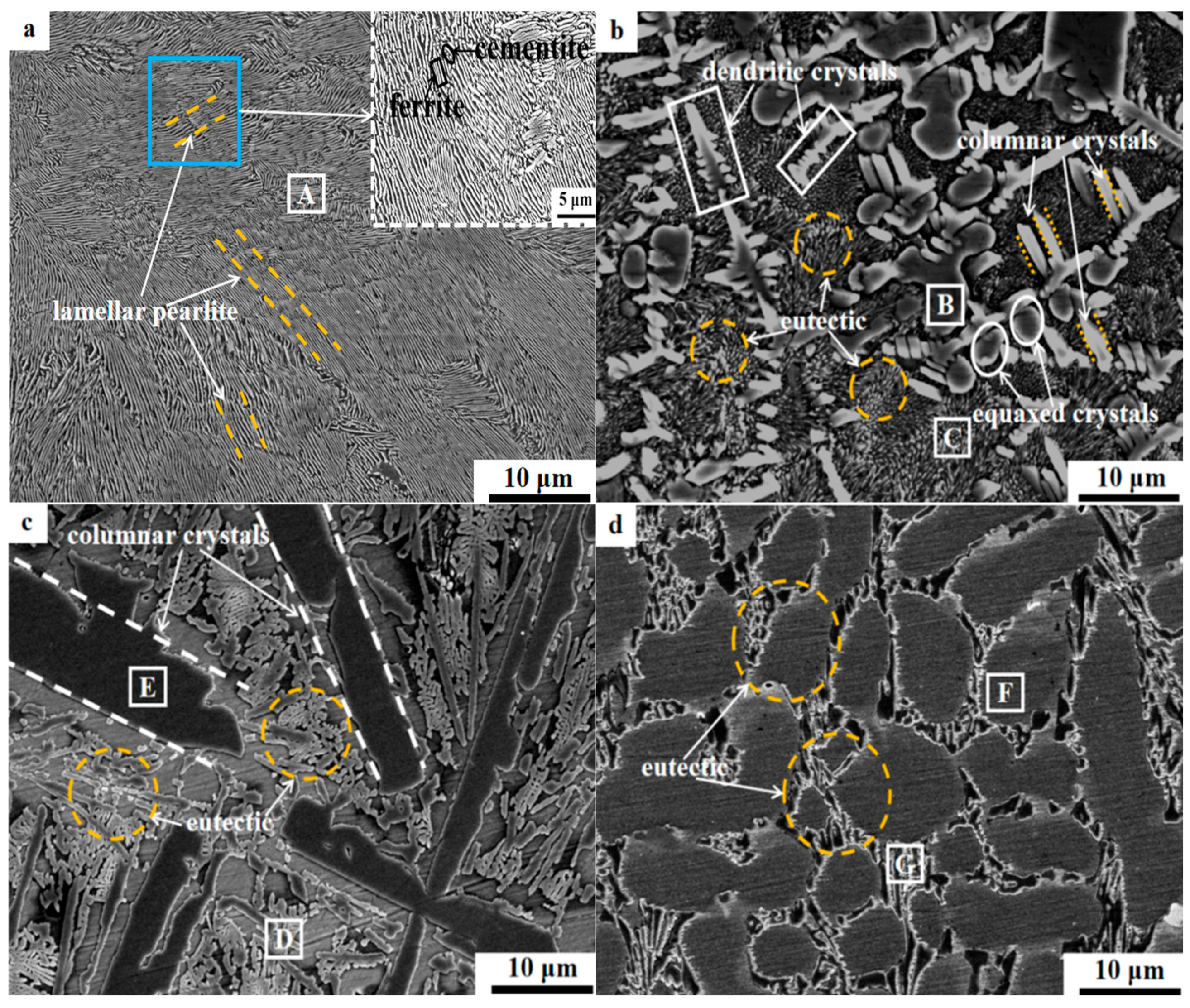
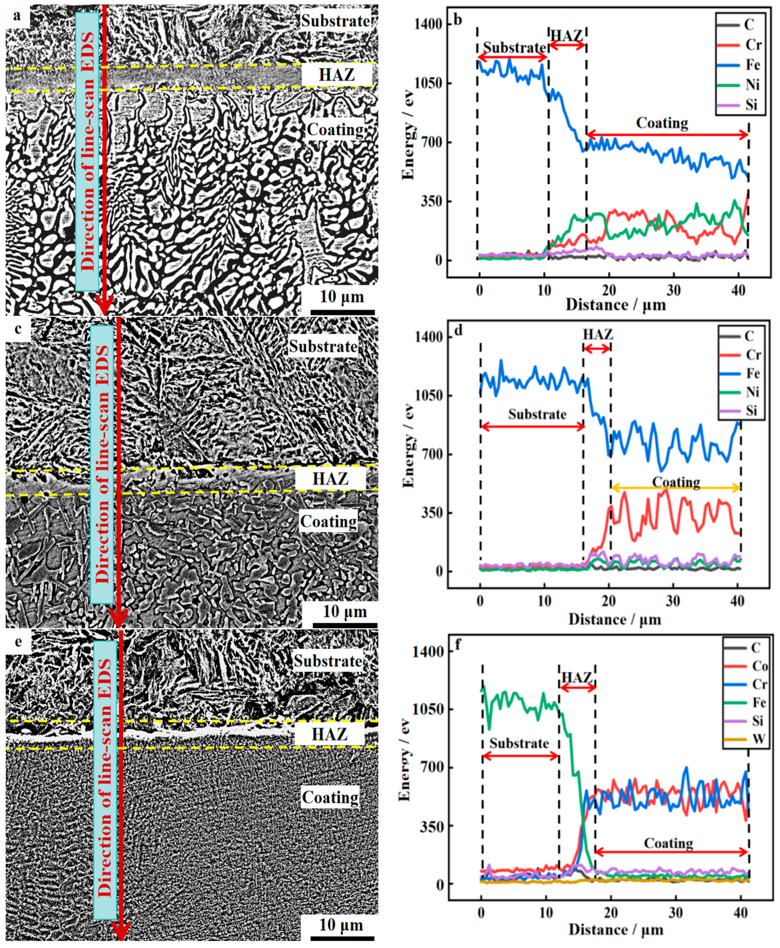
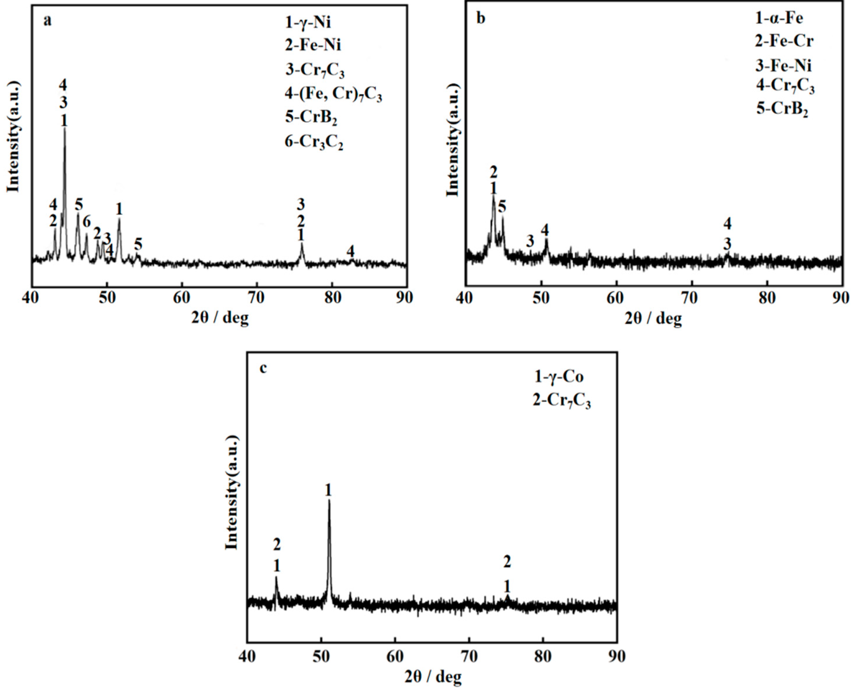
The substrate of U75V steel is characterized by a pearlitic microstructure. The Ni-based coating consists of columnar crystals containing Cr7C3 and Cr3C2, as well as eutectics comprising γ-Ni and CrB2, alongside dendritic and equiaxed structures with relatively fine grain sizes. The Fe-based coating is composed of columnar crystals containing Cr7C3 and a Fe-Cr solid solution, in addition to eutectics comprising α-Fe and CrB2, exhibiting a slight increase in grain size. The Co-based coating is characterized by eutectics containing γ-Co and Cr7C3, displaying the largest grain size among the three coatings.
2.
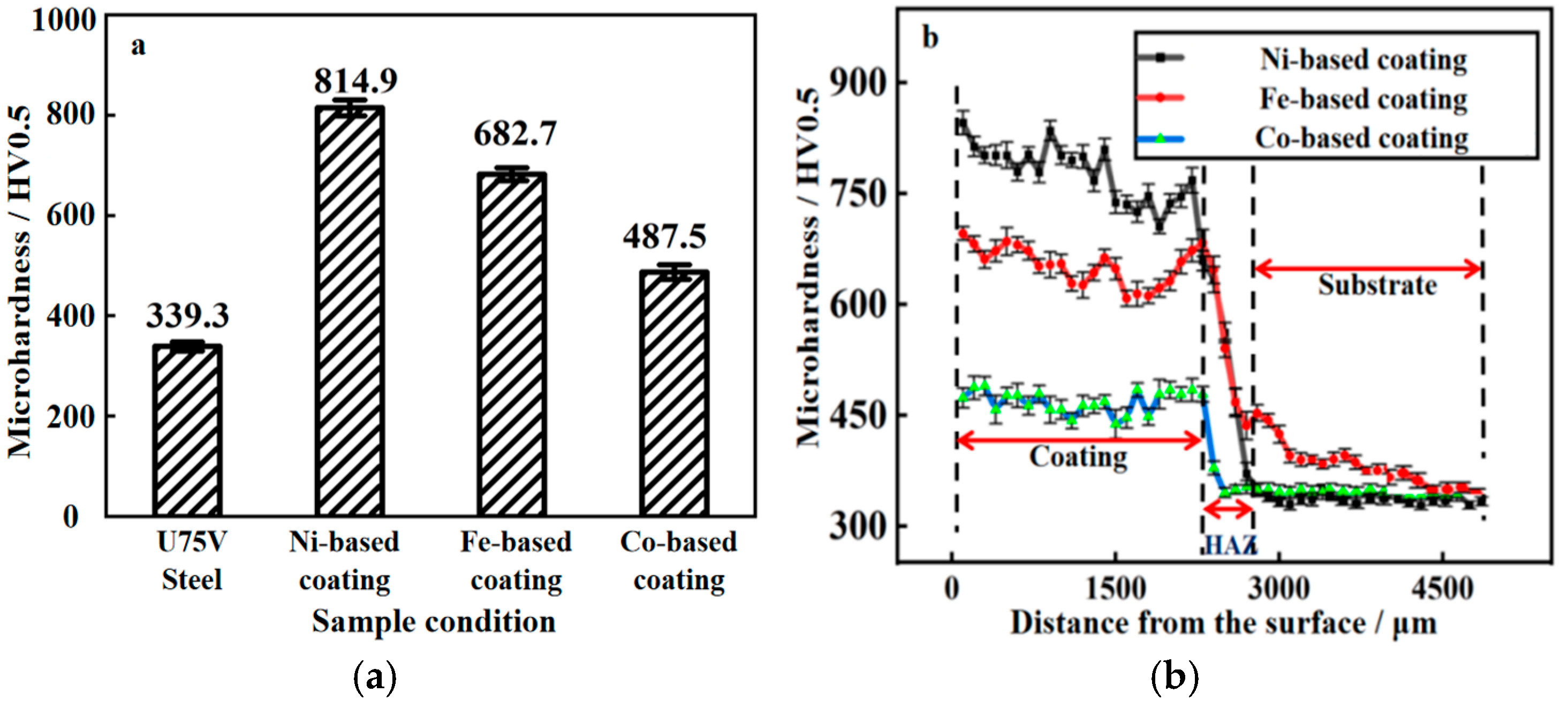
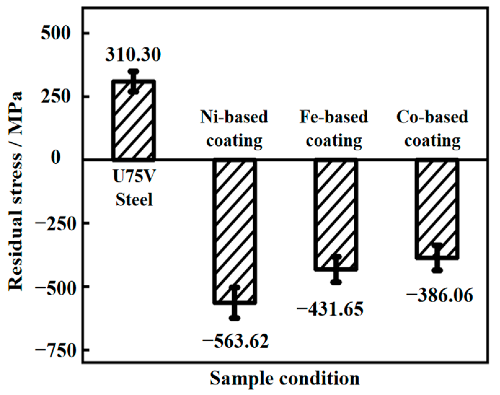
Compared with the substrate hardness of 339.3 HV0.5, the hardness values for the Ni-based, Fe-based, and Co-based coatings are 814.9 HV0.5, 682.7 HV0.5, and 487.5 HV0.5, respectively. The residual stresses measured for the substrate, Ni-based coating, Fe-based coating, and Co-based coating are 310.30 MPa, −563.62 MPa, −431.65 MPa, and −386.06 MPa, respectively.
3.
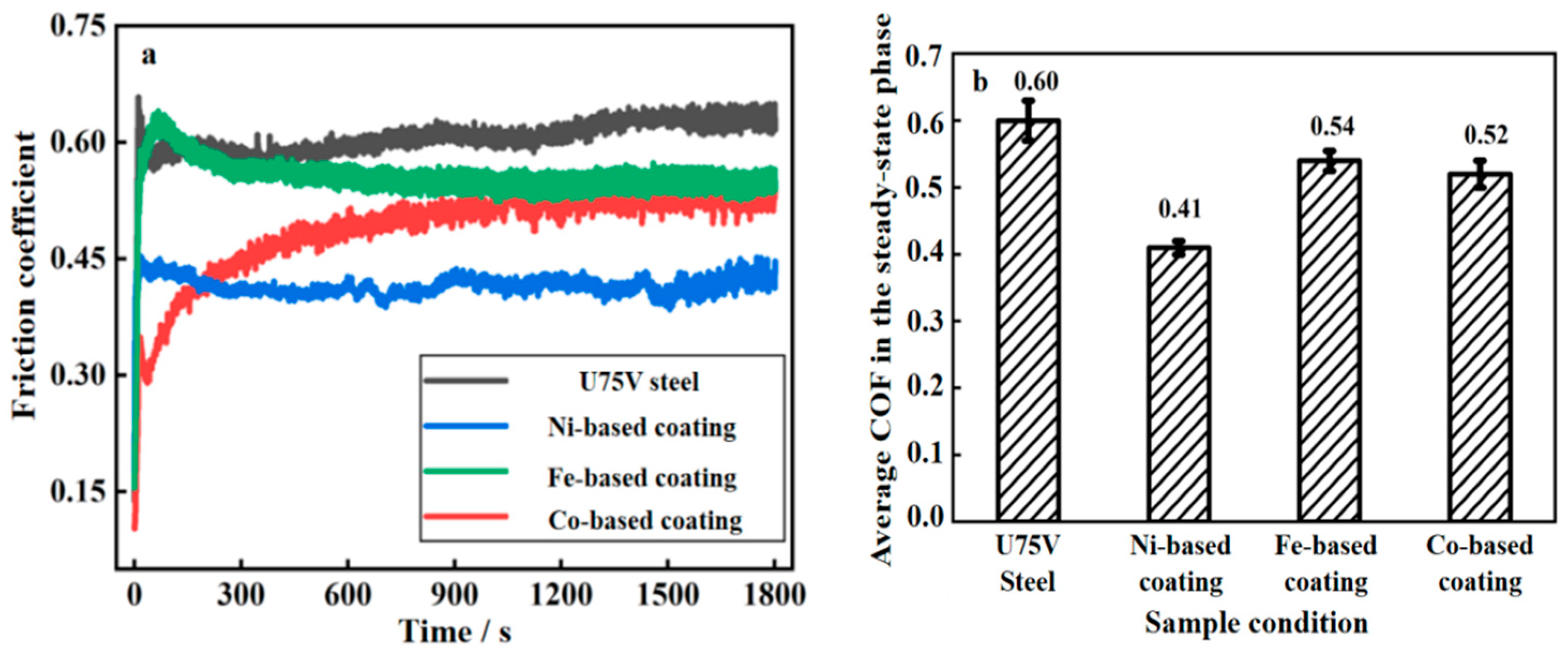
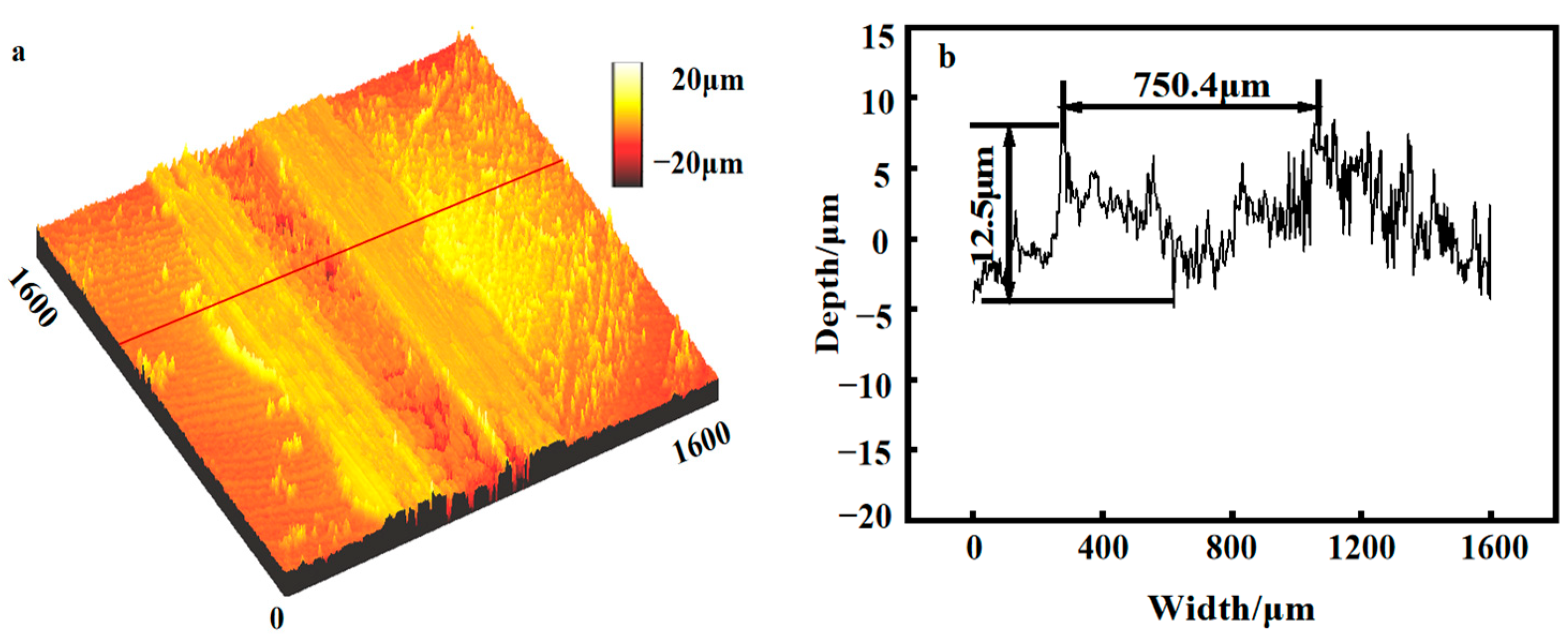
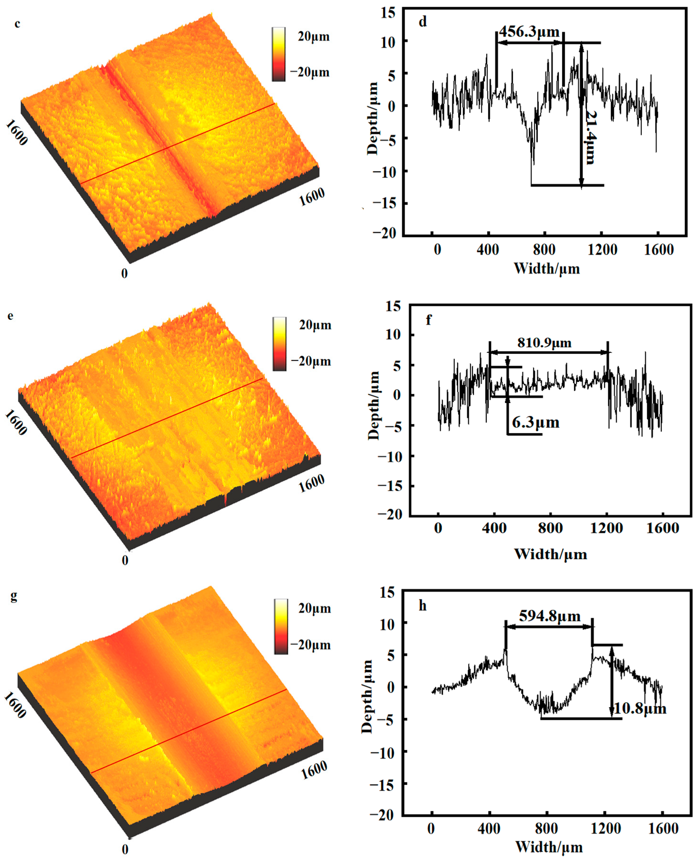
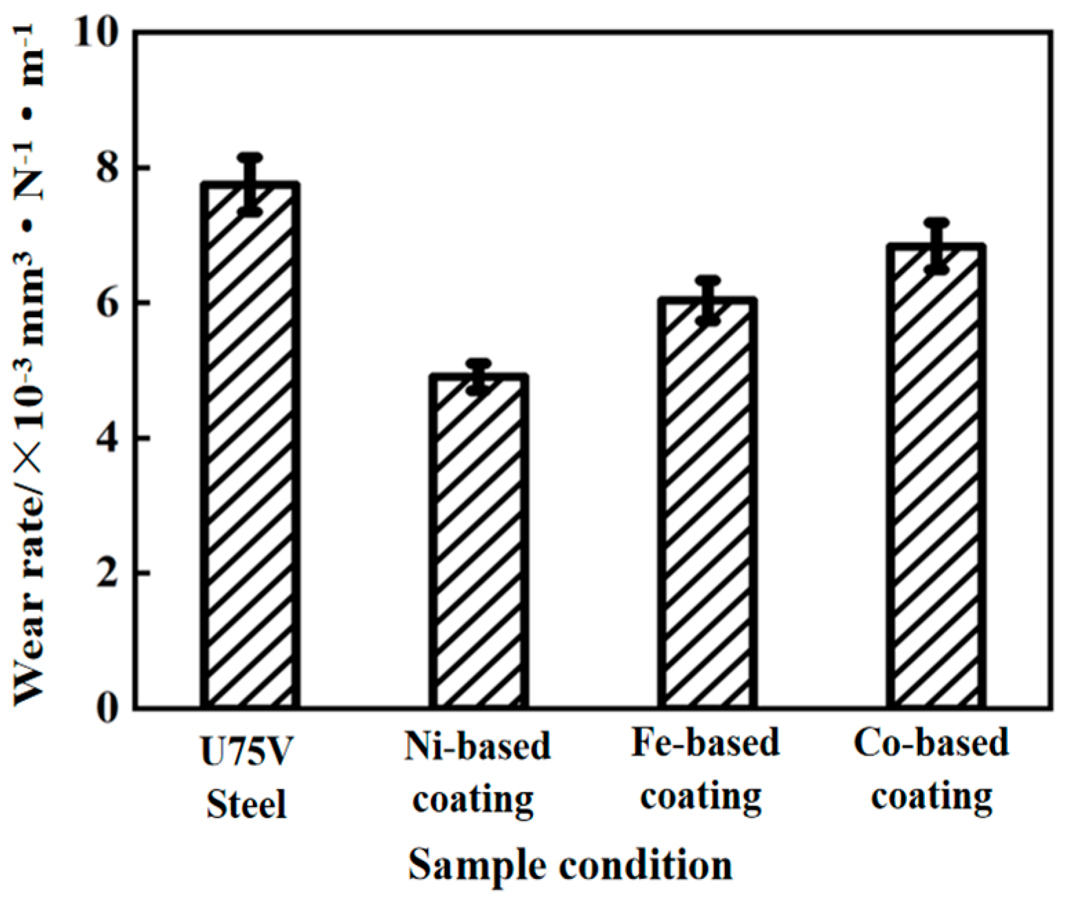
Compared with the substrate, the friction coefficients of the Ni-based, Fe-based, and Co-based coatings were decreased by 32%, 10%, and 14%, respectively. Additionally, the wear rates were reduced by 36.6%, 22.1%, and 11.7%, respectively. Notably, the Ni-based coating exhibited the lowest degree of wear, with wear mechanisms primarily characterized by mild adhesive wear.

Author Contributions

Conceptualization, T.H. and J.T.; methodology, T.H. and J.T.; software, J.T., Z.L. and G.S.; validation, J.T., Z.L. and G.S.; formal analysis, T.H. and J.T.; investigation, T.H. and J.T.; resources, T.H., S.D. and Y.Z.; data curation, J.T.; writing—original draft preparation, J.T.; writing—review and editing, S.D. and Y.Z.; visualization, T.H.; supervision, T.H.; project administration, T.H.; funding acquisition, T.H. and Y.Z. All authors have read and agreed to the published version of the manuscript.

Funding

The project was supported by the Henan Province Science and Technology Research Project (Grant No. 252102220081), the Major Science and Technology Projects of Henan Province (Grant No. 221100210500), and the National Natural Science Foundation of China (Grant No. 51905153).

Data Availability Statement

The original contributions presented in this study are included in the article. Further inquiries can be directed to the corresponding author.

Conflicts of Interest

The authors declare that they have no known competing financial interests or personal relationships that could have appeared to influence the work reported in this paper.

References

  1. Wang, W.J.; Guo, H.M.; Du, X.; Guo, J.; Liu, Q.Y.; Zhu, M.H. Investigation on the damage mechanism and prevention of heavy-haul railway rail. Eng. Fail. Anal. 2013, 35, 206–218. [Google Scholar] [CrossRef]
  2. Wang, W.J.; Jiang, W.J.; Wang, H.Y.; Liu, Q.Y.; Zhu, M.H.; Jin, X.S. Experimental study on the wear and damage behavior of different wheel/rail materials. Proc. Inst. Mech. Eng. Part F-J. Rail Rapid Transit 2016, 230, 3–14. [Google Scholar] [CrossRef]
  3. Xu, W.C.; Zhang, B.B.; Deng, Y.; Wang, Z.Q.; Jiang, Q.T.; Yang, L.H.; Zhang, J. Corrosion of rail tracks and their protection. Corros. Rev. 2021, 39, 1–13. [Google Scholar] [CrossRef]
  4. Mahmoodian, M.; Asl, A.S.; Li, C.Q. Combined effect of rolling contact fatigue and corrosion on structural performance of rails. Aust. J. Struct. Eng. 2020, 21, 320–328. [Google Scholar] [CrossRef]
  5. Maruthamuthu, S.; Nagendran, T.; Anandkumar, B.; Karthikeyan, M.S.; Palaniswamy, N.; Narayanan, G. Microbiologically influenced corrosion on rails. Curr. Sci. 2011, 100, 870–880. [Google Scholar]
  6. Ivanov, Y.; Gromov, V.; Yuriev, A.; Kormyshev, V.; Rubannikova, Y.; Semin, A. Deformation strengthening mechanisms of rails in extremely long-term operation. J. Mater. Res. Technol. 2021, 11, 710–718. [Google Scholar] [CrossRef]
  7. Panda, B.; Balasubramaniam, R.; Moon, A. Microstructure and mechanical properties of novel rail steels. Mater. Sci. Technol. 2009, 25, 1375–1382. [Google Scholar] [CrossRef]
  8. Meng, L.; Zhu, B.B.; Hu, Q.W.; Zeng, X.Y.; Wang, D.Z. Laser-induction hybrid cladding of different coatings on rail surface: Microstructure, wear properties and contact fatigue behaviors. Appl. Surf. Sci. 2021, 566, 150678. [Google Scholar] [CrossRef]
  9. Lewis, S.R.; Lewis, R.; Fletcher, D.I. Assessment of laser cladding as an option for repairing/enhancing rails. Wear 2015, 330, 581–591. [Google Scholar] [CrossRef]
  10. Meng, L.; Zhao, W.F.; Hou, K.L.; Kou, D.H.; Yuan, Z.H.; Zhang, X.; Xu, J.L.; Hu, Q.W.; Wang, D.Z.; Zeng, X.Y. A comparison of microstructure and mechanical properties of laser cladding and laser-induction hybrid cladding coatings on full-scale rail. Mater. Sci. Eng. A 2019, 748, 1–15. [Google Scholar] [CrossRef]
  11. Yang, J.X.; Ma, W.Y.; Zhang, W.T.; Wang, X.J.; Huang, K.; Liu, Z.; Zhou, Z.; Xu, H.C.; Xiao, J.H. The dynamic load-bearing performance of the laser cladding Fe-based alloy on the U75V rail. Int. J. Fatigue 2022, 165, 107180. [Google Scholar] [CrossRef]
  12. Xie, T.X.; Zhou, L.; Ding, H.H.; Zhu, Y.; Yang, W.B.; Xiao, Q.; Wang, W.J.; Guo, J.; Liu, Q.Y. Investigation on the Rolling Contact Fatigue Behaviors of Different Laser Cladding Materials on the Damaged Rail. J. Tribol.-Trans. ASME 2021, 143, 051108. [Google Scholar]
  13. Gao, P.H.; Fu, R.T.; Chen, B.Y.; Zeng, S.C.; Zhang, B.; Yang, Z.; Guo, Y.C.; Liang, M.X.; Li, J.P.; Lu, Y.Q.; et al. Corrosion resistance of CoCrFeNiMn high entropy alloy coating prepared through plasma transfer arc claddings. Metals 2021, 11, 1876. [Google Scholar] [CrossRef]
  14. Xie, G.Z.; Song, X.L.; Zhang, D.J.; Wu, Y.P.; Lin, P.H. Microstructure and corrosion properties of thick WC composite coating formed by plasma cladding. Appl. Surf. Sci. 2010, 256, 6354–6358. [Google Scholar]
  15. Chen, B.Y.; Gao, P.H.; Zhang, B.; Zhao, D.M.; Wang, W.; Jin, C.; Yang, Z.; Guo, Y.C.; Liang, M.X.; Li, J.P.; et al. Wear Properties of Iron-Based Alloy Coatings Prepared by Plasma Transfer Arc Cladding. Coatings 2022, 12, 243. [Google Scholar] [CrossRef]
  16. Liu, Y.F.; Chen, D.Q.; Han, J.M.; Wu, H.; Xu, X.Y.; Yang, S.Z. Microstructure and properties of Cr3Si/γ-Fe composite coating prepared by plasma transferred arc cladding technique. Chin. Phys. Lett. 2009, 26, 095202. [Google Scholar]
  17. Lv, J.J.; Zhang, C.; Chen, Z.Y.; Bai, D.; Zhang, Y.W.; Li, G.S.; Lu, X.G. Fabrication and characterization of Ni60A alloy coating on copper pipe by plasma cladding with induction heating. Coatings 2021, 11, 1080. [Google Scholar] [CrossRef]
  18. Xie, Y.J.; Wen, X.; Huang, B.S.; Zhuang, J. Microstructure, hardness and corrosion properties of AlCoCrFeNi2.1YHf high-entropy alloy coating prepared by plasma cladding. Mater. Lett. 2023, 330, 133356. [Google Scholar] [CrossRef]
  19. Zhu, Y.Z.; Yin, Z.M.; Teng, H. Plasma cladding of Stellite 6 powder on Ni76Cr19AlTi exhausting valve. Trans. Nonferrous Met. Soc. China 2007, 17, 35–40. [Google Scholar]
  20. Sun, Y.F.; Li, Y.T.; Qi, Y.C.; Cai, X.T.; Ma, C.Y. Microstructure and mechanical properties of welded joints between nickel base alloy and 10Ni5CrMoV steel by MIG welding. Mater. Lett. 2022, 328, 133120. [Google Scholar]
  21. Fayazfar, H.; Salarian, M.; Rogalsky, A.; Sarker, D.; Russo, P.; Paserin, V.; Toyserkani, E. A critical review of powder-based additive manufacturing of ferrous alloys: Process parameters, microstructure and mechanical properties. Mater. Des. 2018, 144, 98–128. [Google Scholar]
  22. Fan, L.; Chen, H.Y.; Dong, Y.H.; Li, X.Y.; Dong, L.H.; Yin, Y.S. Corrosion behavior of Fe-based laser cladding coating in hydrochloric acid solutions. Acta Metall. Sin. 2018, 54, 1019–1030. [Google Scholar]
  23. He, T.; Shao, R.; Du, S. Effect of WC content on the friction and wear properties of Ni-WC coatings on 6082-T6 aluminum alloy. Mater. Res. Express 2020, 7, 066530. [Google Scholar]
  24. Yue, Y.; Liu, S.; Qiu, W. Comparative Study on Wear Behaviors of Monolayer and Heterogeneous Multilayer Ta Coatings in Atmospheric and SBF Environments. Coatings 2023, 13, 120. [Google Scholar] [CrossRef]
  25. Wang, X.; Zhang, C.H.; Cui, X.; Zhang, S.; Chen, J.; Zhang, J.B. Novel gradient alloy steel with quasi-continuous ratios fabricated by SLM: Material microstructure and wear mechanism. Mater. Charact. 2021, 174, 111020. [Google Scholar]
  26. Jiang, P.F.; Zhang, C.H.; Zhang, S.; Zhang, J.B.; Chen, J.; Liu, Y. Microstructure evolution, wear behavior, and corrosion performance of alloy steel gradient material fabricated by direct laser deposition. J. Mater. Res. Technol. 2020, 9, 11702–11716. [Google Scholar]
  27. Zhang, H.; Zhang, C.H.; Wang, Q.; Wu, C.L.; Zhang, S.; Chen, J. Effect of Ni content on stainless steel fabricated by laser melting deposition. Opt. Laser Technol. 2018, 101, 363–371. [Google Scholar]
  28. Wu, C.L.; Zhang, S.; Zhang, C.H.; Zhang, H.; Dong, S.Y. Phase evolution and properties in laser surface alloying of FeCoCrAlCuNix high-entropy alloy on copper substrate. Surf. Coat. Technol. 2017, 315, 368–376. [Google Scholar]
  29. Im, H.J.; Dunand, D.C. Microstructure, hardness, and creep of Co-Fe-Ni-based high-entropy superalloy processed by laser powder-bed fusion. Mater. Sci. Eng. A 2024, 916, 147378. [Google Scholar]
  30. Wang, X.; Li, J. Study of the wear resistance of an Fe60/WC composite coating by ultrasonic assisted laser cladding. Sci. Rep. 2025, 15, 8559. [Google Scholar]
  31. Clare, A.; Oyelola, O.; Folkes, J.; Farayibi, P. Laser cladding for railway repair and preventative maintenance. J. Laser Appl. 2012, 24, 032004. [Google Scholar] [CrossRef]
  32. Lin, T.T.; Chen, S.H.; Chiu, C. Properties of Al0.5CoCrFeNi2Ti High-Entropy Alloy System: From Gas-Atomized Powders to Atmospheric Plasma-Sprayed Coatings. J. Therm. Spray Technol. 2024, 33, 2839–2852. [Google Scholar] [CrossRef]
  33. Zhang, C.H.; Wu, S.Q.; He, S.W.; Zhang, S.; Wu, C.L.; Guan, M.; Tan, J.Z.; Cui, W.D. Cavitation erosion properties of Ni-based RE alloy coating on monel alloy by laser cladding. Rare Met. Mater. Eng. 2018, 47, 1517–1522. [Google Scholar]
  34. Hu, Z.Y.; Li, Y.; Lu, B.W.; Tan, N.; Cai, L.R.; Yong, Q.S. Effect of WC content on microstructure and properties of high-speed laser cladding Ni-based coating. Opt. Laser Technol. 2022, 155, 108449. [Google Scholar] [CrossRef]
  35. Zhang, F.Y.; Duan, C.Z.; Sun, W.; Ju, K. Influence of white layer and residual stress induced by hard cutting on wear resistance during sliding friction. J. Mater. Eng. Perform. 2019, 28, 7649–7662. [Google Scholar]
  36. Roy, T.; Paradowska, A.; Abrahams, R.; Law, M.; Mutton, P.; Soodi, M.; Yan, W.Y. Residual stress in laser cladded heavy-haul rails investigated by neutron diffraction. J. Mater. Process. Technol. 2020, 278, 116511. [Google Scholar] [CrossRef]
  37. Hua, X.J.; Tian, Z.X.; Xie, X.; Zhang, P.Y.; Xu, J.F.; Zhu, Y.H.; Du, H.; Yin, B.F. Tribological behavior and abrasion resistance mechanism of laser micro-bulge texturing surface under full oil lubrication. Tribol. Trans. 2020, 63, 726–735. [Google Scholar] [CrossRef]
  38. Li, S.C.; Mo, B.; Xiao, G.; Sun, F.J. Microstructure characteristics and their influence factors during laser additive manufacturing of metal materials. Laser Optoelectron. Prog. 2021, 58, 0100007. [Google Scholar]
  39. Gaumann, M.; Bezençon, C.; Canalis, P.; Kurz, W. Single-crystal laser deposition of superalloys: Processing–microstructure maps. Acta Mater. 2001, 49, 1051–1062. [Google Scholar] [CrossRef]
  40. Liu, S.; Shin, Y.C. Additive manufacturing of Ti-6Al-4V alloy: A review. Mater. Des. 2019, 164, 107552. [Google Scholar] [CrossRef]
  41. Yao, W.J.; Wei, B.B. Microstructural evolution during containerless rapid solidification of Co-Si alloys. Chin. Phys. 2003, 12, 1272–1282. [Google Scholar]
  42. Naik, S.N.; Walley, S.M. The Hall–Petch and inverse Hall–Petch relations and the hardness of nanocrystalline metals. J. Mater. Sci. 2020, 55, 2661–2681. [Google Scholar]
  43. Zhang, J.Y.; Wu, K.; Zhang, L.Y.; Wang, Y.Q.; Liu, G. Unraveling the correlation between Hall-Petch slope and peak hardness in metallic nanolaminates. Int. J. Plast. 2017, 96, 120–134. [Google Scholar]
  44. Armstrong, R.W.; Balasubramanian, N. Unified Hall-Petch description of nano-grain nickel hardness, flow stress and strain rate sensitivity measurements. AIP Adv. 2017, 7, 085010. [Google Scholar] [CrossRef]
  45. Sun, S.T.; Fu, H.G.; Ping, X.L.; Lin, J.; Lei, Y.P. Reinforcing behavior and microstructure evolution of NbC in laser cladded Ni45 coating. Appl. Surf. Sci. 2018, 455, 160–170. [Google Scholar]
  46. Han, B.; Li, M.Y.; Wang, Y. Microstructure and wear resistance of laser clad Fe-Cr3C2 composite coating on 35CrMo steel. J. Mater. Eng. Perform. 2013, 22, 3749–3754. [Google Scholar]
  47. Zhao, J.B.; Wang, Y.; Han, B.; Li, M.; Cui, G. Antifriction effects of Cu2S film on Ni-based MMC coating. Surf. Coat. Technol. 2017, 315, 391–398. [Google Scholar]
  48. Ye, Z.Y.; Liu, Z.Y.; Li, J.N.; Su, Q.; Zhao, B.; Zhang, S.Z.; Guan, D.W.; Li, H.B.; Li, H.; Zhang, Z.F. Argon-arc cladding of Q235 low-carbon steel by Co base alloy deposition. Surf. Rev. Lett. 2021, 28, 2150017. [Google Scholar]
  49. Ye, W.T.; Xie, M.D.; Huang, Z.B.; Wang, H.M.; Zhou, Q.; Wang, L.; Chen, B.; Wang, H.F.; Liu, W.M. Microstructure and tribological properties of in-situ carbide/CoCrFeNiMn high entropy alloy composites synthesized by flake powder metallurgy. Tribol. Int. 2023, 181, 108295. [Google Scholar]
  50. Huang, S.M.; Sun, D.Q.; Wang, W.Q. Microstructures and properties of Ni based composite coatings prepared by plasma spray welding with mixed powders. Int. J. Refract. Met. Hard Mater. 2015, 52, 36–43. [Google Scholar] [CrossRef]
  51. Larue, J.E.; Daniewicz, S.R. Predicting the effect of residual stress on fatigue crack growth. Int. J. Fatigue 2007, 29, 508–515. [Google Scholar] [CrossRef]
  52. Gee, M.G.; Gant, A.; Roebuck, B. Wear mechanisms in abrasion and erosion of WC/Co and related hardmetals. Wear 2007, 263, 137–148. [Google Scholar]
Figure 1. The micro-morphology of the three alloy powders and particle size statistics: (a) Ni-based powder; (b) Fe-based powder; (c) Co-based powder.
Metals 15 00344 g001
Figure 2. The surface microstructure of different samples: (a) U75V Steel; (b) the Ni-based coating; (c) the Fe-based coating; (d) the Co-based coating.
Metals 15 00344 g002
Figure 3. Different coatings’ cross-section line-scan EDS results: (a,b) the Ni-based coating; (c,d) the Fe-based coating; (e,f) the Co-based coating.
Metals 15 00344 g003
Figure 4. The different coatings’ XRD patterns: (a) the Ni-based coating; (b) the Fe-based coating; (c) the Co-based coating.
Metals 15 00344 g004
Figure 5. The hardness of different samples: (a) Surface hardness of different samples. (b) Cross-sectional gradient hardness of different coatings.
Metals 15 00344 g005
Figure 6. The residual stress of the four samples.
Metals 15 00344 g006
Figure 7. The samples’ friction coefficient: (a) friction coefficient; (b) average friction coefficient in the steady-state phase.
Metals 15 00344 g007
Figure 8. The three-dimensional morphology of wear surface of different samples (The red lines on the left figures indicate the positions corresponding to the 2D profiles of the wear scar on the right figures): (a,b) U75V Steel; (c,d) the Ni-based coating; (e,f) the Fe-based coating; (g,h) the Co-based coating.
Metals 15 00344 g008aMetals 15 00344 g008b
Figure 9. The wear rate of different samples.
Metals 15 00344 g009
Figure 10. The wear morphologies of four samples: (a) U75V Steel; (b) the Ni-based coating; (c) the Fe-based coating; (d) the Co-based coating.
Metals 15 00344 g010
Table 1. The U75V Steel’s chemical composition (wt. %).
ElementCSiMnPSVFe
Wt/%0.750.610.920.0250.0060.006Bal.
Table 2. The chemical compositions of different alloy powders (wt. %).
TypeCSiBWCrFeNiCo
Ni-based1.04.03.6-18.05.0Bal.-
Fe-based0.81.64.1-17.0Bal.11.0-
Co-based1.11.0-4.417.028.51.5Bal.
Table 3. Plasma cladding process parameters.
ParametersCurrent/AFeeding Rate/(mm/min)
Ni110100
Fe12595
Co12080
Table 4. The findings of the EDS scan at the designated location in Figure 2 (wt. %).
AreaFeNiCCrSiWCo
A89.4/10.6////
B16.47.115.660.80.1//
C39.1512.24.13.6//
D73.47.56.212.10.8//
E65.212.37.814.10.6//
F13.63.71.420.11.72.357.2
G21.42.92.649.30.84.318.7
Disclaimer/Publisher’s Note: The statements, opinions and data contained in all publications are solely those of the individual author(s) and contributor(s) and not of MDPI and/or the editor(s). MDPI and/or the editor(s) disclaim responsibility for any injury to people or property resulting from any ideas, methods, instructions or products referred to in the content.

