Article

Impact of Novel Nozzles on Atomization Flow Field and Particle Features: Simulation and Experimental Validation

1
School of Materials Science and Engineering, Northeastern University, Shenyang 110819, China
2
Shenyang National Laboratory for Materials Science, Institute of Metal Research, Chinese Academy of Sciences, Shenyang 110016, China
*
Authors to whom correspondence should be addressed.
Metals 2025, 15(3), 313; https://doi.org/10.3390/met15030313
Submission received: 5 February 2025 / Revised: 7 March 2025 / Accepted: 11 March 2025 / Published: 13 March 2025

Abstract

Gas-atomized powder characteristics significantly impact additive manufacturing processes. Two innovative nozzles, semi-converging–diverging nozzle type II and fully converging–diverging nozzle type III, were designed based on the traditional cylindrical nozzle type I. Utilizing the k-ε model and Discrete Phase Model (DPM), the flow field evolution and powder characteristics of these nozzles were analyzed at gas pressures ranging from 4 to 8 MPa. The results indicate that in the gas-phase flow field both nozzle type II and nozzle type III can achieve a performance comparable to that of nozzle type I at significantly lower gas pressures. Specifically, nozzle type II operates effectively with a reduction of approximately 1 MPa compared to nozzle type I, while nozzle type III demonstrates an even greater advantage with a pressure reduction of about 2 MPa. In the gas–melt-phase flow field, nozzle type III still has the effect of reducing the pressure by approximately 2 MPa compared to nozzle type I. The melt fracture process under nozzle type III is divided into three distinct stages: the formation of large droplets, a transition area for fragmentation, and a fully fragmented region. This research effectively reduces energy losses and offers novel insights as well as recommendations for applications related to atomization technology.

1. Introduction

In recent years, additive manufacturing (AM) has experienced rapid development, attributed to its advantages such as a high design freedom, efficient material utilization, strong customization capabilities, and low production costs. However, the quality of manufactured components is significantly influenced by the properties of the powder. Therefore, producing high-quality powder particles has become a focal point of current research and concerns [1,2,3,4,5,6,7,8,9]. The methods for producing powder particles are diverse, primarily including gas atomization, water atomization, and combined gas–water atomization. Among these techniques, gas atomization has emerged as the predominant method for metal powder production due to its ability to yield powders with stable properties and a low impurity content [10]. The fundamental principle of gas atomization involves utilizing a high-speed, low-temperature gas jet to impact liquid alloy melt, resulting in its fragmentation. The larger droplets that are formed subsequently undergo spheroidization due to surface tension and are then rapidly cooled at an extremely high cooling rate, yielding solidified micron-sized spherical particles. The gas atomization process comprises three stages: primary atomization, secondary atomization, and cooling solidification. After the molten metal exits from the bottom of the delivery tube, it undergoes fragmentation into millimeter-sized parent droplets due to the action of high-velocity gas flow: this process is referred to as primary atomization. Following this stage, under continued influence of the gas flow in the recirculation zone below, the parent droplets are further broken down into smaller micron-sized daughter droplets: this phenomenon is called secondary atomization [11]. The factors influencing the particle size of atomized powders in industrial applications are varied, with a particular emphasis on nozzle design and atomization pressure. Notably, the advent of Laval atomizing nozzles has played a pivotal role in the production of finer powder particles [12,13,14,15].
The process of atomization and powder production typically occurs within a few tens of milliseconds, making it difficult to observe and record with the naked eye. Therefore, simulation tools are employed to visualize the specific fragmentation processes and analyze the flow field conditions, providing theoretical guidance for practical applications [16]. With advancements in computer technology, computational fluid dynamics (CFD) has become the mainstream method for studying gas atomization. Among these methods, the Volume of Fluid (VOF) model is commonly used to simulate primary atomization processes, while the Discrete Phase Model (DPM) is frequently applied to secondary atomization processes [17]. In recent years, numerous studies utilizing computational fluid dynamics (CFD) methods have made significant contributions to the detailed elucidation of the atomization process. Zeoli et al. [18] omitted the complex simulation of gas–liquid multiphase flow during a single atomization process and directly calculated the fragmentation process of particles with diameters ranging from 1 to 5 mm. Sheng Luo et al. [19] have developed a novel approach that combines similarity theory with Navier–Stokes equations to directly simulate the entire process of gas atomization. Li-Chong Zhang [20] employed a simulation approach utilizing the SST k-ω turbulence model, the Taylor Analogy Breakup (TAB) model, and the Discrete Phase Model (DPM) to analyze the secondary fragmentation process. This study identified three distinct types of satellite collision events. Li and Fritsching [21] employed a detailed Volume of Fluid (VOF) technique to simulate the initial fragmentation process and utilized the Euler–Lagrange approach to investigate the secondary fragmentation. Liu et al. [11] conducted an investigation into the flight and cooling processes of particles under various operational parameters. The findings reveal that the average particle diameter (d50) is significantly affected by gas–liquid interactions, exhibiting a decrease as the gas–liquid ratio (GMR) increases. Wang et al. [22] addressed the issue of nozzle clogging by precisely controlling the atomization sequence, specifically by initiating the gas flow prior to pooling the alloy (AG) and pouring the alloy before activating the gas (GA) through vacuum induction melting gas atomization (VIGA).
In order to achieve higher export velocities and finer powder particle sizes, numerous researchers have dedicated themselves to the study of the geometric structures of gas atomization nozzles. Urionabarrenetxea et al. [23], through the study of different intake pressures and different throat widths of supersonic gas nozzles, vividly demonstrated how these two parameters similarly modify the gas mass flow rate, the gas velocity field, the aspiration pressure in the melt-conveying pipe, or the size of the recirculation zone beneath the melt nozzle. Zeoli et al. [24] developed an isentropic plug nozzle (IPN) that, in comparison to traditional annular slit nozzles (ASNs), significantly mitigates shock waves and optimizes the transfer of kinetic energy from the gas to the unstable melt. This advancement substantially enhances powder yield. Due to the variation in atomization yield, which can reach up to 42% in median powder size (D50) under conditions above and below the so-called trailing-edge closure pressure, Ting et al. [25,26] conducted a study on the gas dynamics of annular slit high-pressure gas atomization nozzles under open- and closed-trailing-edge conditions. The results indicated that at lower atomizing gas pressures, the flow field exhibited an open trailing state. However, when the atomizing gas pressure reached 4.82 MPa, a closed trailing phenomenon was observed in the flow field. Wang et al. [27] developed an innovative tightly integrated dual-nozzle system and examined the effects of variations in primary and secondary pressures on the gas flow dynamics, melt atomization process, and characteristics of the resulting particles. These characteristics include particle dimensions, sphericity, and the occurrence of satellite particle formation. Zhao et al. [28] designed tightly coupled gas atomization nozzles with different exit gas Mach numbers to investigate the distribution of nozzle exit gas pressure, velocity, temperature, and the structural characteristics of the flow field at the nozzle outlet. The results indicate that nozzles operating at high Mach numbers can produce finer powders at faster cooling rates. To better leverage the advantages of gas atomization production in terms of powder particle size, it is crucial to gain a detailed understanding of the design mechanisms underlying atomization nozzle structures.
The powder particles under high pressure (5–8 MPa) exhibit advantages such as good sphericity, optimal particle size, and a more concentrated distribution. However, practical production faces challenges including excessive energy loss and safety hazards. In our previous work [29], we established a numerical model for multiphase flow during the secondary atomization process in a closed vortex at pressures ranging from 5 to 8 MPa to investigate the melt fragmentation behavior and defect droplet evolution under different pressure parameters. Building on these atomization results, we upgraded the traditional cylindrical converging nozzle type I (NTI) by designing the semi-converging–diverging nozzle type II (NTII) and the fully converging–diverging nozzle type III (NTIII). These new designs achieve effects comparable to those obtained with high atomization gas pressures in NTI while operating at lower atomization pressures. Subsequently, a detailed investigation was conducted on the secondary atomization and fragmentation process of NTIII under a closed-vortex state at 5 MPa. This study also analyzed the fragmentation process of powder particles. This work provides valuable insights into gas atomization with respect to energy efficiency and production safety.

2. Numerical Modeling and Experimental Procedure

2.1. Gas Atomization Model

According to the structural characteristics of the tightly coupled gas atomization system, the actual axisymmetric three-dimensional gas field is simplified into a two-dimensional axisymmetric region as shown in Figure 1c, rotated counterclockwise by 90°. The computational domain extends from the end of the gas nozzle to the bottom outlet, measuring 100 mm in length and 30 mm in width. For the designed three types of nozzles, NTI consists of a discrete jet nozzle symmetrically formed by 18 individual nozzles: specifically, a ring orifice type. NTII and NTIII utilize annular slit designs. High-pressure nitrogen and high-temperature molten alloy enter the atomization chamber through their respective gas outlet and delivery tube ends. Mesh generation was performed using Gambit 2.4.6, resulting in total node counts for NTI, NTII, and NTIII of 97,323, 94,419, and 96,075, respectively. The corresponding mesh counts are 158,275, 15,368, and 157,126, respectively. The minimum element size is set at 0.1 mm. Following mesh generation, simulations were conducted using Fluent version 19.2 for solving equations and post-processing. The computational domain’s walls are considered to maintain a constant temperature of 300 K, whereas the melt hole is set at 1600 K with the exit pressure matching the ambient pressure. Essential thermodynamic properties for nitrogen gas and the alloy melt [30,31,32] are summarized in Table 1 and Table 2. For boundary conditions, the gas inlet nozzle is defined as the pressure inlet boundary, the sides and bottom of the atomization chamber are defined as pressure outlet boundaries, while all remaining surfaces are designated as wall boundaries.

2.2. Nozzle Design Mechanism

In the study of flow in variable cross-section pipes, a key formula is involved, which is as follows [33]:
d V V = 1 M a 2 1 d A A
where p represents pressure, ρ represents density, V represents velocity, T represents temperature, M a represents the Mach number, and k represents the adiabatic index of the gas.
Based on the Laval nozzle mechanism, this study designed NTII and NTIII on the basis of NI. Since both NTII and NTIII adopt the design principle of the Laval nozzle, the shape of the nozzle of type III will be used for illustration below. The two-dimensional model of the atomizing nozzle is illustrated in Figure 2. The fluid at the nozzle exit originates from a gas reservoir, which is referred to as the stagnation chamber. The entire nozzle is divided into three sections: the convergent section, throat section, and divergent section. During the convergent section of the nozzle, the flow remains subsonic; at the throat section of the nozzle, the velocity reaches sonic speed; and in the divergent section of the nozzle, the flow transitions to supersonic speeds.
Assuming that the airflow is isentropic, the relationship between the exit pressure at the nozzle and the throat pressure can be expressed as follows [34]:
P e P 0 = 1 + k 1 2 M a e 2 k 1 k
where P e represents the outlet pressure, P 0 denotes the atomization pressure, k indicates the adiabatic index of gas, and the gas Mach number at the outlet is denoted as M a e .
The exit area of the converging–diverging nozzle and the throat area conform to the isentropic area ratio formula as follows [34]:
A e A 0 = 1 M a [ 1 + k 1 2 M a 2 ( 2 k + 1 ) ] k + 1 2 ( k 1 )
where A 0 represents the throat area and A e denotes the outlet area.

2.3. Modeling the Fluid

In fluid dynamics, the flow of fluids is governed by three fundamental laws, including the law of conservation of mass, which states that the total mass of the system remains constant during the fluid flow process. The second law is the law of conservation of momentum, which is based on Newton’s second law and uses the principle of action and reaction as a theoretical tool. The external force applied to the fluid causes a conserved energy exchange within the fluid. The last law is the law of conservation of energy, which means that the total energy of the system must also remain conserved. The above three laws are given by the following relations [35]:
The continuity equation satisfies the following formula:
( ρ u i ) x i = 0
The momentum equation is given by the following formula:
( ρ u i u j ) x i = p x i + x i ( u e f f u j x i )
The energy equation conforms to the following formula:
( ρ u i h ) x i = u j ρ x i + x i K e f f h x i + Φ
In Formulas (10)–(12), u i represents the mean velocity component, h denotes the mean static enthalpy, x i signifies the spatial position, p refers to the mean pressure, ρ is the mean density, the parameters u e f f and K e f f correspond to the effective viscosity and effective thermal conductivity, respectively, and Φ stands for the viscous dissipation function.

2.4. The Discrete Particle Model

The gas–liquid two-phase flow field in this paper is studied based on the DPM model. In this model, the movement trajectory of particles can be predicted through the force balance equation, and the specific formula is as follows [36]:
m p d   u p d t = m p u u p F D + m p g x ( ρ p ρ ) ρ p + F x
where m p represents the mass of the particles, u denotes the velocity of the continuous phase, u p indicates the velocity of the particles, ρ refers to the density of the continuous phase, ρ p signifies the density of the particles, F x stands for additional forces, m p u u p F D corresponds to particle resistance, and F D represents the drag force.
F D = 18 u ρ p d p 2 C D R e d 24
where the droplet Reynolds number R e d is defined by the following:
R e d = ρ | u u p | D u
The drag coefficient C D is obtained from the following expressions:
C D = 0.44 ( f o r   R e d > 1000 )
C D = ( 1 + 0.15 R e d 0.687 ) R e d / 24   ( f o r   R e d 1000 )
The equilibrium equation for droplet heating is expressed as follows:
m d C p L d T d d t = K N u D z e z 1 π D 2 T T d + Q L d m d d t
where
z = C p f u d m d d t ( π D K m N u )
N u = 2 + 0.6 R e d 1 / 2 P r 1 / 3

2.5. Materials

The material utilized in this study was the Fe50Cr18Mo7.5Ni3.5P12B3C3.5Si2.5 (at.%) alloy. This alloy, characterized by its specific metallic and non-metallic composition, was produced through the induction melting of high-purity elements: Fe: 99.7, Cr: 99.9, Mo: 98.5, Ni: 99.9, FeB: 99% (22.06 wt.% boron), FeP (21.20 wt.% phosphorus), C: (99.9%), and Si: (99.9%) (Shenyang Institute of Metal Research, Shenyang, China). The entire process was conducted under a high-purity nitrogen atmosphere to ensure optimal conditions for alloy formation. Amorphous powders were prepared using a gas atomization equipment (Shenyang Institute of Metal Research, Shenyang, China) at different atomization pressures ranging from 4 to 8 MPa, with the maximum temperature being approximately 1600 K. The inner diameter of the melt pouring tube was 3 mm, and the mass flow rate of the melt was about 0.08 kg/s. The powder prepared by gas atomization was subjected to deoxidation and dehumidification treatment, and its morphology was observed by scanning electron microscopy (SEM, Zeiss Supra55).

3. Results and Discussion

3.1. The Gas-Phase Flow Field Characteristics of Three Distinct Nozzle Types

The content in Figure 3a1–e3 presents a gas-phase computational fluid dynamics model of three types of nozzles (NTI, NTII, NTIII) at gas pressures ranging from 4 to 8 MPa in the closed-wake condition. When the gas enters the atomization chamber, its pressure decreases while its velocity increases sharply, resulting in the formation of a series of expansion waves at the nozzle exit. The gas continues to accelerate, generating internal shock waves and recompression shocks until it reaches a stable state. In NTI (4–6 MPa), the main characteristics include both primary and secondary recirculation zones. Notably, there exists a stagnation point (where the velocity is zero) below the primary recirculation zone along the axis, while two stagnation points are present within the secondary recirculation zone. Additionally, a “bowed” Mach disk appears at the front end of these stagnation points. As atomization pressure increases, the position of the secondary recirculation zone gradually shifts downward. In NTI (7 MPa), a small third recirculation zone emerges at the lower end of the secondary recirculation zone, which also contains two stagnation points along its axis. Consequently, there are now five stagnation points along this entire central axis. In NTI (8 MPa), there is an approach and connection between the secondary and third recirculation zones. In addition to maintaining their original primary and secondary structures, an extended third recirculation zone is formed as well.
In NTII (4–5 MPa), the secondary recirculation zone is a prominent feature. However, in NTII (6 MPa) a small third recirculation zone appears at the lower end of the secondary recirculation zone, similar to that observed in NTI (7 MPa). In NTII (7 MPa), an extended third recirculation zone forms; in addition to the primary and secondary recirculation zones, this phenomenon resembles what occurs in NTI (8 MPa). In NTII (8 MPa), both the secondary and extended third recirculation zones shift downward along the axis and elongate as a whole. A comparative analysis of flow fields between NTI and NTII suggests that achieving identical flow field conditions under different atomization gas pressures requires approximately 1 MPa less pressure for NTII than for NTI.
In NTIII (4 MPa), the secondary recirculation zone is its main characteristic. However, in NTIII (5 MPa), a small third recirculation zone appears at the lower end of the secondary recirculation zone, similar to that observed in NTI (7 MPa). In NTIII (6 MPa), an extended third recirculation zone forms, a phenomenon akin to what is seen in NTI (8 MPa). In NTIII (7–8 MPa), the secondary and extended third recirculation zones merge into a unified super-large extended secondary recirculation zone. Comparing the flow fields of NTI and NTIII suggests that achieving the same flow field state under different atomization gas pressures requires approximately 2 MPa less pressure for NTIII than for NTI. These observations indicate that NTIII demonstrates greater superiority in reducing energy loss.
Figure 4 illustrates the static pressure curves along the centerline of three nozzles (NTI, NTII, NTIII) at gas atomization pressures ranging from 4 to 8 MPa. The static pressure values at the base of the diversion pipe initially increase, reaching a peak at the stagnation point (indicated by the green dotted arrow), before subsequently decreasing. After passing through the Mach disk (as indicated by the black dotted arrow), there is another increase in static pressure values, leading to the emergence of second and third stagnation points (marked by brown dotted arrows). The region between these stagnation points constitutes what is referred to as the secondary circulation zone. As the pressure rises to a certain threshold, additional stagnation points—the third and fourth—become apparent (denoted by red dotted arrows). At this juncture, the area situated between these new stagnation points represents what can be termed as the third recirculation zone. Notably, upon comparing the pressure curves for all three nozzles across different atomization pressures, it becomes evident that when NTII operates at an atomization pressure approximately 1 MPa lower than that of NTI, its static pressure curve is similar to that of NTI. Similarly, when NTIII’s atomization pressure is about 2 MPa lower than that of NTI, its static pressure curve is also akin to that of NTI. This observation correlates well with the airflow field cloud map presented in Figure 3.
The aspiration pressure values at the bottom of the diversion pipe are presented in Figure 5 at gas atomization pressures ranging from 4 to 8 MPa. In Figure 5a, it can be observed that, except for NT III at atomization pressures of 7 MPa and 8 MPa, all other atomization pressures satisfy the negative pressure condition. This ensures the smooth outflow of the alloy melt. In Figure 5b, the maximum static pressure values for NTI, NTII, and NTIII increase with rising atomization pressure. Notably, the maximum static pressure value for NTIII is significantly higher than the values for NTI and NTII across different atomization pressures. This discrepancy may be attributed to the design characteristics of NTIII, which features a full contraction–divergence mechanism. As a result, the outlet gas flow pressure is considerably greater than the surrounding environmental pressure, leading to strong shock waves acting along the axis.
The velocity curves along the central axis for three types of nozzles under different atomization pressures (4–8 MPa) in closed-vortex states are presented in Figure 6a1–e3. In NTI, at pressures ranging from 4 to 6 MPa, during the primary circulation phase, the airflow enters the atomization chamber through the nozzle and generates a shock wave. Under high-pressure kinetic energy, the gas velocity instantaneously reaches supersonic speeds. Due to the sharp angle convergence of the airflow upon ejection, the maximum pressure energy impacts a single point, which becomes a stagnation point where the velocity is zero. Subsequently, part of this airflow reverses along the axis and counteracts with incoming flow from below via the guiding tube, forming a primary circulation zone. Meanwhile, another portion continues to move axially until it encounters an arcuate Mach disk, where its speed abruptly decreases. The influence of this Mach disk results in both downstream and upstream flows along the axis, thereby creating a secondary circulation zone. In contrast to conditions at 6 MPa, when the atomization pressure reaches 7 MPa not only does it establish primary and secondary circulation zones but it also gives rise to a smaller tertiary circulation zone at remote ends of the axis. The formation mechanism of this tertiary circulation zone is fundamentally similar to that of the secondary one.
Similar to the conclusion drawn in Figure 3, when the same speed curve characteristics are achieved under different atomization pressures, the pressure required by NTII is approximately 1 MPa lower than that of NTI, while the pressure required by NTIII is approximately 2 MPa lower than that of NTI.
Figure 7a–c summarize the three common recirculation zone structures of the three types of nozzles, and the following parameters are used as the criteria for the evolution of the flow field: Atomization pressure (AP); Position of the maximum gas velocity (PMV); Maximum gas velocity value (MVV); Initial position of the secondary recirculation zone (IPSZ); Length of the secondary recirculation zone (LSZ); Initial position and length of the third recirculation zone (IPTZ - LTZ). The specific parameter values are summarized in Table 3.
Table 3 presents the parameter values of three types of nozzles at different atomization pressures. Firstly, the PWM and MVV of the three nozzles (NTI, NTII, NTIII) increase with the rise in atomization pressure. Based on preliminary conclusions drawn from Figure 3, Figure 4 and Figure 6, NTI (6 MPa) with the characteristic of a secondary circulation zone is taken out and compared with NTII (5 MPa) and NTIII (4 MPa). The values of MVV, IPSZ, and LSZ in NTII (5 MPa) are all higher than those in NTI (6 MPa), indicating that when achieving the same state, NTII reduces the pressure by approximately 1 MPa compared to NTI. In contrast, for NTIII (4 MPa), although the LSZ value is relatively high, all other parameters are lower than those of NTI (6 MPa). This suggests that when achieving the same state, the pressure reduction of nozzle III compared to nozzle I is less than 2 MPa. NTI (7 MPa), characterized by three-cycle zone properties, is compared with NTII (6 MPa) and NTIII (5 MPa). The parameter values of NTII (6 MPa) are generally consistent with those of NTI (7 MPa). In contrast, the parameter values in NTIII (5 MPa) exceed those of NTI (7 MPa), indicating that, compared to NTI, NTIII does not exhibit a linear increase with a slope of 1 in terms of reducing energy loss as the atomization gas pressure increases. In summary, NTIII demonstrates a significantly greater advantage in minimizing energy losses.

3.2. The Gas–Melt-Phase Flow Field Characteristics of Two Distinct Nozzle Types

Figure 8 shows the gas–liquid flow fields and the velocity profiles along the geometric centerline of two types of nozzles (NTI and NTIII) at gas atomization pressures ranging from 4 to 7 MPa. Due to the ability of NTI to achieve complete amorphization at pressures of 6 MPa and 7 MPa, and considering that NTIII offers a significant advantage by operating at a reduced pressure of 2 MPa compared to NTI within the gas-phase flow field, this study focuses on investigating the gas–liquid two-phase behavior for NT I (6–7 MPa) and for NTIII (4–5 MPa). Overall, after the alloy melt enters the atomization chamber a significant change occurs in the flow field. Firstly, NTI and NTIII exhibit similar flow field characteristics. Specifically, compared to a gas-phase flow field, the primary circulation zone of the gas–liquid two-phase flow is reduced. This reduction is attributed to the inflow of alloy melt, which diminishes the reverse airflow along the axis due to its influence. Furthermore, both nozzles display analogous structures in their secondary recirculation zones. Notably, there exists a high-speed shock wave region at the front end of these zones. In contrast, within NTI and NTIII it is observed that as pressure increases, so does the velocity of the high-speed shock wave region. Additionally, both locations for secondary circulation zones shift backward while their lengths increase with rising pressure levels. A comparison of velocity profiles along the axis for NTI and NTIII leads to conclusions akin to those derived from the gas-phase flow field: that NTIII (4 MPa) cannot achieve the effect of NTI (6 MPa). However, when both are increased by 1 MPa, the high-speed shock wave region velocity for NTIII (5 MPa) reaches 658 m/s, while that for NTI (7 MPa) is measured at 610 m/s. This indicates that NTIII (5 MPa) exhibits superior characteristics compared to NTI (7 MPa).
When the atomization pressure is 7 MPa, the amorphous content of the powder is the highest and the cooling rate is the greatest [37]. Therefore, Figure 9 shows the vector diagrams of the gas–liquid two-phase flow field of NTI (7 MPa) and NTIII (5 MPa), and the corresponding particle breakage regions.
Firstly, both NTI (7 MPa) and NTIII (5 MPa) exhibit similar characteristics. Due to the lower velocity and incompressibility of molten droplets, the size of the primary recirculation zone is reduced. Following this primary recirculation zone, the airflow velocity gradually increases until it reaches a high-speed shock wave region. Subsequently, under the influence of a “Z”-shaped Mach disk, there is a sudden deceleration that leads to the formation of a secondary recirculation zone. This secondary recirculation zone is divided into two parts by an axis line: below this axis line, airflow circulates counterclockwise within its respective region; above it, airflow circulates clockwise. These two sections facilitate further fragmentation of large liquid droplets that have been broken down in the primary circulation zone. At the tail end of the secondary recirculation zone, airflow continues to move downward along the axis at low speed. This process repeats itself until ultimately leading to particle cooling and solidification.
In the gas–liquid two-phase flow field, the gas jet impacts the discrete phase particles. After the flow field stabilizes (about 40 ms), the particle images of NTI (7 MPa) and NTIII (5 MPa) are compared. In the particle images, red particles represent the largest particles (approximately 160–200 μm), yellow and green particles represent medium-sized particles (approximately 60–160 μm), and blue particles represent smaller particles (approximately 10–60 μm). Through image comparison, after the secondary recirculation zone breaks the particles NTI (7 MPa) has more medium-sized particles (measured by the width of the green part). The number of large-sized particles that are not fully broken in NTI (7 MPa) is also greater than that in NTIII (5 MPa) (indicated by the yellow dashed circles, i.e., the red particles within the circles). In the second half of the breaking process, most of the large-sized red particles in both NTI (7 MPa) and NTIII (5 MPa) are broken into medium- and small-sized particles. However, compared with NTIII (5 MPa), NTI (7 MPa) still contains a small number of large-sized particles and relatively more medium-sized particles (indicated by the red circles). This observation indicates that the breaking effect of NTIII (5 MPa) is better than that of NTI (7 MPa).
The analysis focuses on the droplet fragmentation process of NTIII (5 MPa). It is evident that the fragmentation process can be divided into three distinct phases. In Region A, large-sized particles are initially formed. In Region B, which corresponds to the high-speed shock wave area, the gas velocity along the axis is excessively high, causing particles to be carried downstream with the gas flow. As a result, it becomes challenging for these particles to experience sufficient impact for effective fragmentation. Thus, this phase serves as a transitional stage. In Region C, under the influence of vortices and reverse airflow in the secondary recirculation zone, the droplet fragmentation process occurs repeatedly, leading to thorough fragmentation and resulting in smaller droplets.

3.3. Verification

The scanning electron microscopy (SEM) images of Fe-based alloy amorphous powders with diameters ranging from 25 to 100 μm, produced by NTI and NTIII at atomization pressures of 7 MPa and 5 MPa, respectively, are presented in Figure 10a,b. From Figure 10a, that is, at NTI (7 MPa), it can be seen that most of the powder particles present relatively complete spherical shapes, while a few extremely irregular particles take on shapes such as satellites, short bars, dumbbells, and filaments. However, from Figure 10b, that is, under the condition of NTIII (5 MPa), these irregular powder particles are mostly in the shapes of ellipses and satellites (there are fewer extremely irregular shapes). The reasons for the appearance of these morphologies lie in the fact that both NTI (7 MPa) and NTIII (5 MPa) have relatively high gas pressures, increasing the probability of droplet collisions. This causes small droplets to adhere to the surface of large droplets, forming satellite structures. However, NTIII, utilizing its contraction–expansion characteristics, has a lower pressure at the gas outlet but a higher velocity. This results in droplets not being immediately broken into fine short bars (due to the lower pressure), but the interaction between gas and liquid is enhanced (due to the higher velocity), leading to a higher degree of sub-division. In addition, the particle size distribution of both conforms to a normal distribution, and the median particle size of NTIII (5 MPa, d50 = 52.2 μm) is slightly smaller than that of NTI (7 MPa, d50 = 52.5 μm). On the whole, NTIII (5 MPa) has a certain advantage in generating smaller particles after crushing.

4. Conclusions

The present study builds upon the traditional converging NTI to design two new types of nozzles: the annular seam semi-converging–diverging NTII and the fully converging–diverging NTIII. The flow field structure under 4–8 MPa was obtained through the k-ε model and DPM model, and the superiority of NTII and NTIII in reducing energy loss was clarified. The liquid fragmentation process of NTIII at 5 MPa was analyzed. The main research results are as follows:
(1)
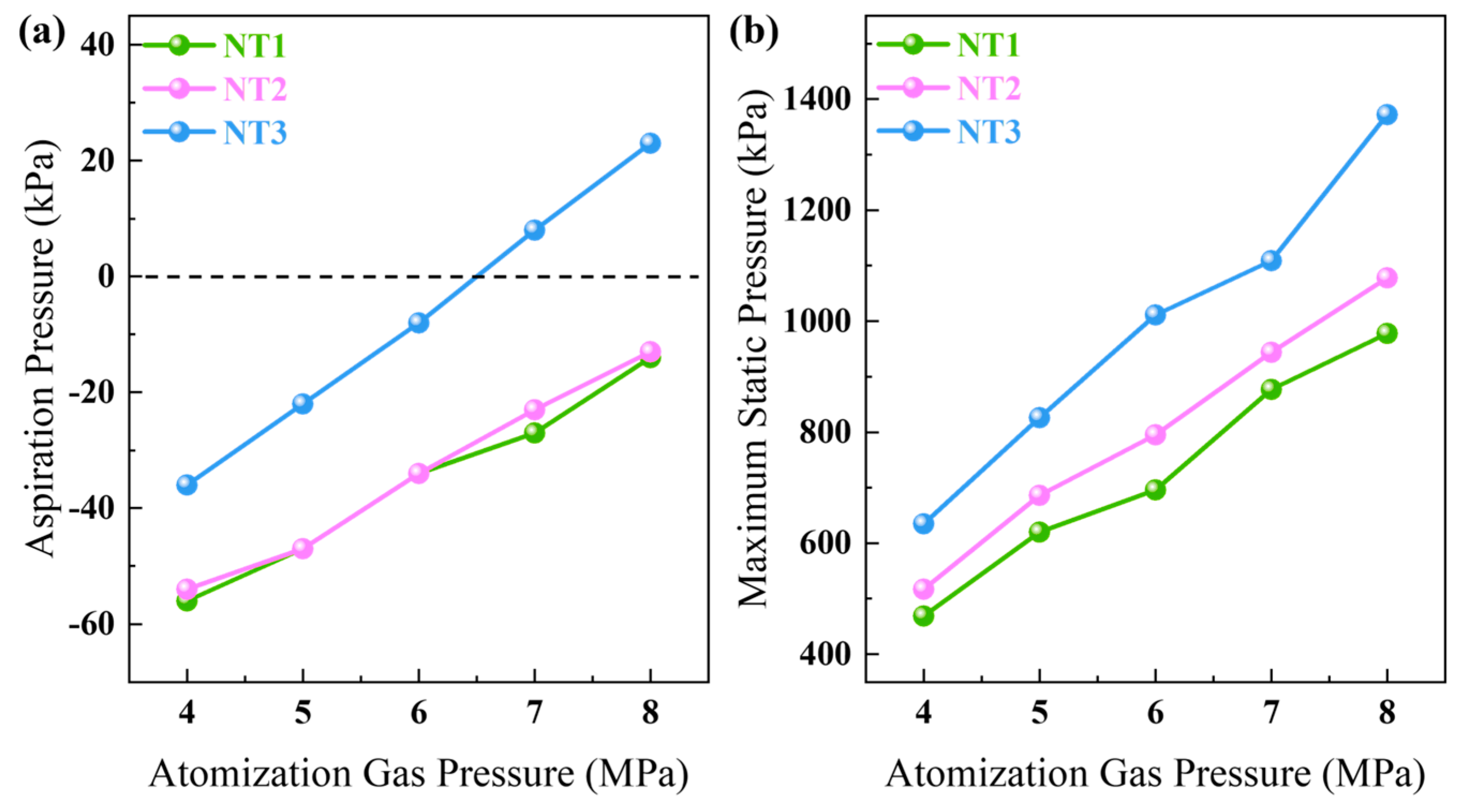
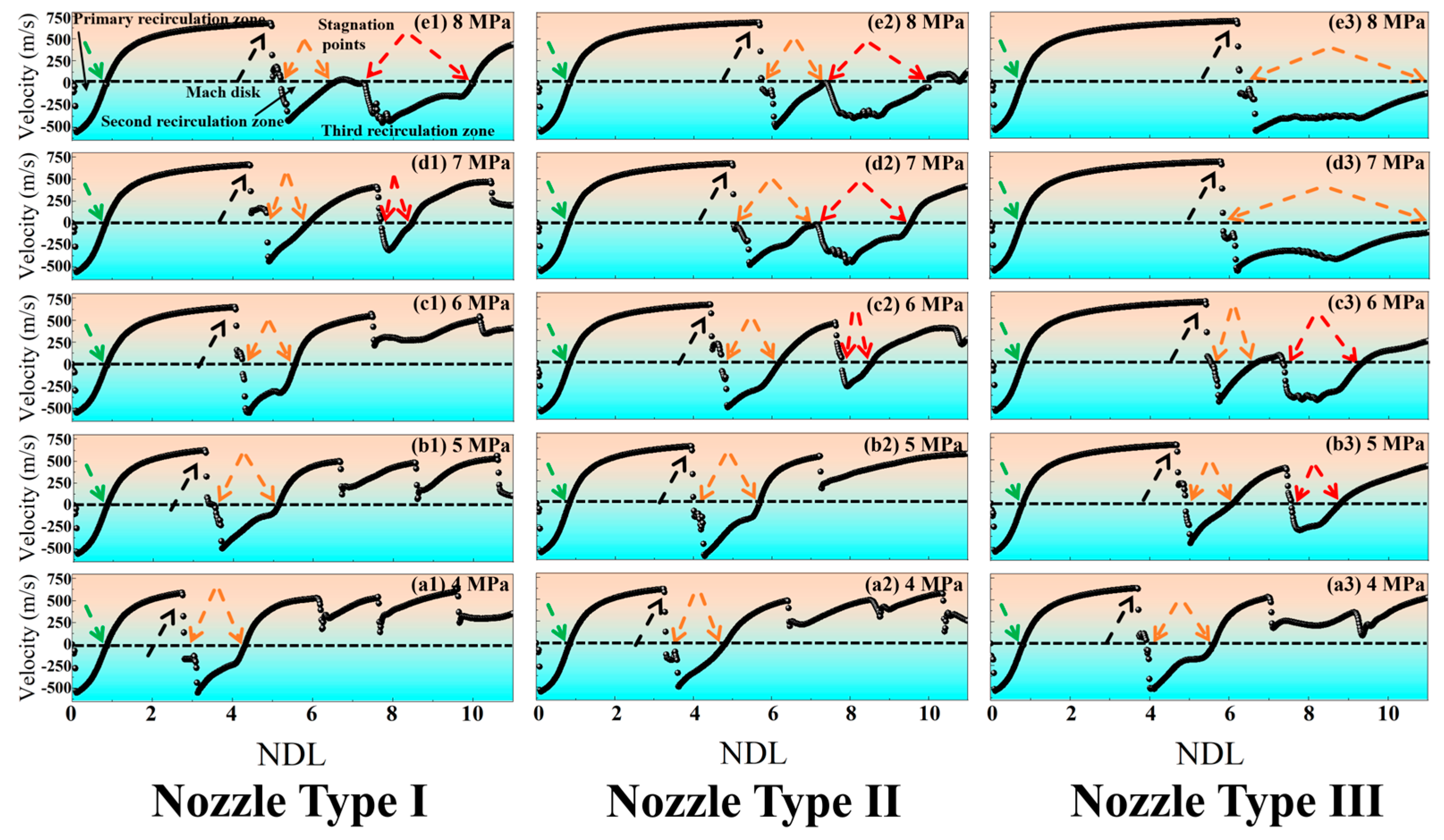
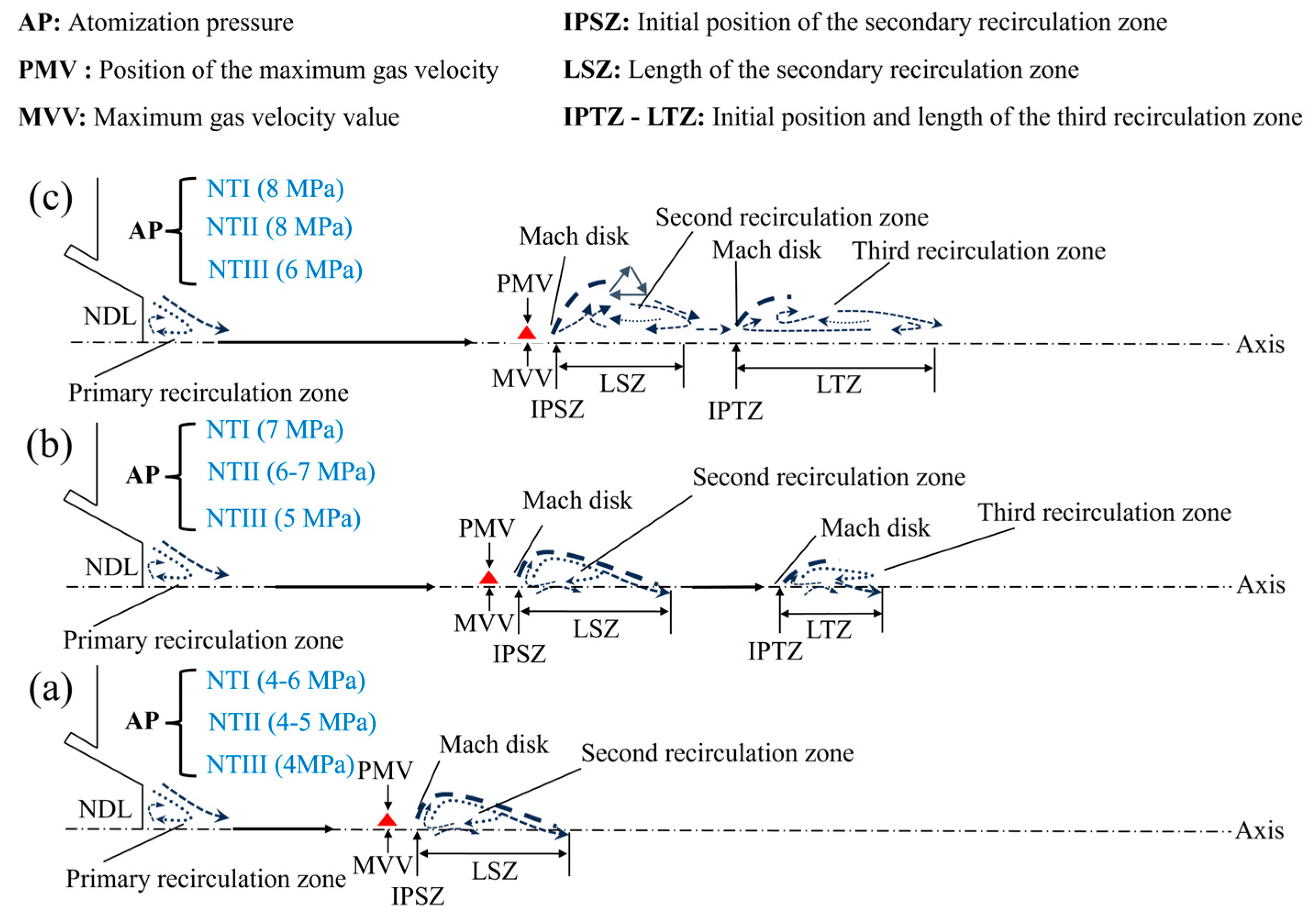
In the gas-phase flow field, at NTI (4–6 MPa), NTII (4–5 MPa), and NTIII (4 MPa) only primary and secondary recirculation zones are present. At NTI (7 MPa), NTII (6 MPa), and NTIII (5 MPa), in addition to retaining characteristics of primary and secondary recirculation zones, a small third recirculation zone also emerges. When operating at NTI (8 MPa), NTIII (7–8 MPa), or NTIII (6 MPa), not only do the primary and secondary recirculation zone features persist, but the length of the third recirculation zone is also extended. Through preliminary analysis of the gas-phase airflow field, it can be inferred that when reaching the same state, NTII operates approximately 1 MPa lower than NTI, while NTIII functions about 2 MPa lower than spraying with NTI. Compared to both NTI and NTII, NTIII demonstrates a greater advantage in reducing energy loss.
(2)
In the gas-phase flow field, a comparison of parameters such as PMV, MVV, IPSZ, LSZ, and IPTZ-LTZ indicates that NTII achieves a reduction of approximately 1 MPa compared to NTI while maintaining the same state. However, when achieving the same state at NTIII (4 MPa), the pressure drop relative to NTI (6 MPa) is less than 2 MPa. Furthermore, all parameter values for NTIII (5 MPa) are higher than those for NTI (7 MPa). This observation suggests that as the atomization pressure increases in NTIII, the enhancement in flow field intensity no longer follows a linear relationship with a slope of 1. Instead, it exhibits nonlinear growth characterized by a slope greater than 1.
(3)
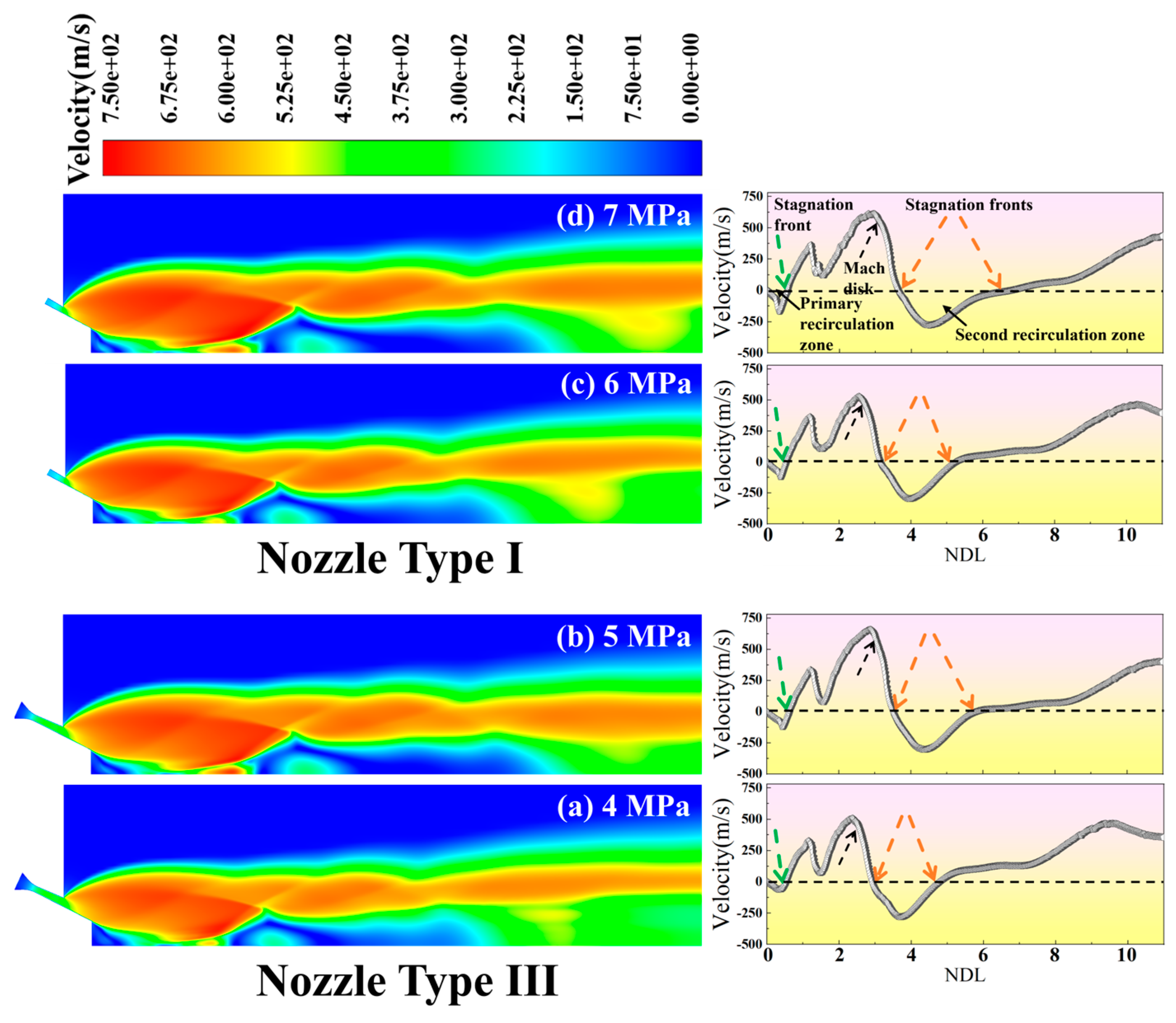
In the gas–liquid two-phase flow field, NTI (6–7 MPa) and NTIII (4–5 MPa) exhibit a reduction in the size of the initial recirculation zone compared to the gas-phase flow field. Following the primary recirculation zone, the gas velocity gradually increases, rapidly forming a high-speed shock wave region along the central axis where velocity reaches its peak. Subsequently, under the influence of the “Z” Mach disk, there is a sudden deceleration that leads to the formation of a secondary recirculation zone. The central axis divides this secondary recirculation zone into two distinct parts: one aligned with and one opposing the gas flow. Notably, NTIII (5 MPa) demonstrates a superior fragmentation performance compared to NTI (7 MPa). The particle fragmentation process can be categorized into three regions: A (formation of large droplets), B (transition area for fragmentation), and C (fully fragmented region).

Author Contributions

Methodology, Investigation, Writing—original draft, Writing—review and editing, K.W.; Methodology, Writing—original draft, Writing—review and editing, Z.Z.; Methodology, Data curation, Resources, Writing—review and editing, W.S.; Methodology, Data curation, Y.Z.; Methodology, Data curation, S.Z.; Conceptualization, Methodology, Writing—original draft, Writing—review and editing, Resources, Project administration, J.W. All authors have read and agreed to the published version of the manuscript.

Funding

This work was supported by the National Natural Science Foundation of China (Nos. 52171163, 52471186), the Key Research Program of the Chinese Academy of Sciences (No. ZDRW-CN-2021-2-2), and the “Strategic Priority Research Program” of the Chinese Academy of Sciences (No. XDA041040404).

Data Availability Statement

The original contributions presented in this study are included in the article. Further inquiries can be directed to the corresponding authors.

Conflicts of Interest

The authors declare no conflicts of interest.

References

  1. Ünal, A.; Naylor, M.J.; McShane, H.B. Modelling of Metal Powder Production Using a Wax Atomiser. Powder Metall. 2013, 33, 260–268. [Google Scholar] [CrossRef]
  2. Ünal, A. Effect of processing variables on particle size in gas atomization of rapidly solidified aluminium powders. Sci. Technol. 2013, 3, 1029–1039. [Google Scholar] [CrossRef]
  3. Özbilen, S.; Ünal, A.; Sheppard, T. Influence of Liquid Metal Properties on Particle Size of Inert Gas Atomised Powders. Powder Metall. 2013, 39, 44–52. [Google Scholar] [CrossRef]
  4. Ünal, R. Improvements to close coupled gas atomisation nozzle for fine powder production. Powder Metall. 2013, 50, 66–71. [Google Scholar] [CrossRef]
  5. Zheng, M.; Zhang, S.; Zhao, W. A novel crucible-less inert gas atomisation method of producing titanium powder for additive manufacturing. Powder Metall. 2018, 62, 15–21. [Google Scholar] [CrossRef]
  6. Yu, S.; Zhang, P.; Li, J. Preparation and characterization of 316L spherical powder for different uses by supersonic laminar flow atomization. Ferroelectrics 2018, 530, 25–31. [Google Scholar] [CrossRef]
  7. Arachchilage, K.H.; Haghshenas, M.; Kumar, R. Numerical simulation of high-pressure gas atomization of two-phase flow: Effect of gas pressure on droplet size distribution. Adv. Powder Technol. 2019, 30, 2726–2732. [Google Scholar] [CrossRef]
  8. Zhang, M.; Zhang, Z.M. Numerical simulation study on cooling of metal droplet in atomizing gas. Mater. Today Commun. 2020, 25, 101423. [Google Scholar] [CrossRef]
  9. Akhlaghi, F.; Esfandiari, H. Solid-assisted melt disintegration (SAMD), a novel technique for metal powder production. Mater. Sci. Eng. A 2007, 452, 70–77. [Google Scholar] [CrossRef]
  10. Mandal, S.; Sadeghianjahromi, A.; Wang, C.C. Experimental and numerical investigations on molten metal atomization techniques—A critical review. Adv. Powder Technol. 2022, 33, 103809. [Google Scholar] [CrossRef]
  11. Liu, J.; Wang, P.; Zhang, J. Investigation on close-coupled gas atomization for Fe-based amorphous powder production via simulation and industrial trials: Part I. Melt breakup behaviors during primary atomization. J. Mater. Res. Technol. 2023, 27, 6568–6580. [Google Scholar] [CrossRef]
  12. Schwenck, D.; Ellendt, N.; Uhlenwinkel, V. A novel convergent–divergent annular nozzle design for close-coupled atomization. Powder Metall. 2007, 60, 198–207. [Google Scholar] [CrossRef]
  13. Anderson, E.; Terpstra, R.L. Progress toward gas atomization processing with increased uniformity and control. Mat. Sci. Eng. A 2022, 326, 101–109. [Google Scholar] [CrossRef]
  14. Si, C.R.; Zhang, X.J.; Li, Y.J. Design and evaluation of a Laval-type supersonic atomizer for low-pressure gas atomization of molten metals. Int. J. Miner. Metall. Mater. 2014, 21, 627–635. [Google Scholar] [CrossRef]
  15. Xu, L.H.; Zhou, X.L.; Yu, Y.G. Numerical Simulations of Molten Breakup Behaviors of a de Laval-Type Nozzle, and the Effects of Atomization Parameters on Particle Size Distribution. Processes 2020, 8, 1027. [Google Scholar] [CrossRef]
  16. Luo, S.; Wang, H.; Wang, H. Interaction between high-velocity gas and liquid in gas atomization revealed by a new coupled simulation model. Mater. Des. 2021, 212, 110264. [Google Scholar] [CrossRef]
  17. Moghaddam, O.; Shaburova, N.A.; Trofimov, E.A. Additive manufacturing of high entropy alloys: A practical review. J. Mater. Sci. Technol. 2021, 77, 131–162. [Google Scholar] [CrossRef]
  18. Zeoli, N.; Gu, S. Numerical modelling of droplet break-up for gas atomization. Comput. Mater. Sci. 2006, 38, 282–292. [Google Scholar] [CrossRef]
  19. Luo, S.; Ouyang, Y.; Wang, H. 3D numerical modeling of gas atomization process for powder preparation based on similarity theory. Powder Technol. 2024, 433, 119244. [Google Scholar] [CrossRef]
  20. Zhang, L.C.; Xu, W.Y.; Zhang, G.Q. Mechanism of rapidly solidified satellites formation in gas atomized powders: Simulation and characterization. Powder Technol. 2023, 418, 118162. [Google Scholar] [CrossRef]
  21. Li, X.G.; Fritsching, U. Process modeling pressure-swirl-gas-atomization for metal powder production. J. Mater. Process. Technol. 2017, 239, 1–17. [Google Scholar] [CrossRef]
  22. Wang, J.F.; Xia, M.; Ge, C.C. Precise control of atomization initial stage to address nozzle clogging issue in the vacuum induction-melting gas atomization process. J. Mater. Res. Technol. 2024, 30, 1505–1517. [Google Scholar] [CrossRef]
  23. Urionabarrenetxea, E.; Martín, J.M.; Rivas, A. Simulation and validation of the gas flow in close-coupled gas atomisation process: Influence of the inlet gas pressure and the throat width of the supersonic gas nozzle. Powder Technol. 2022, 407, 117688. [Google Scholar] [CrossRef]
  24. Zeoli, N.; Gu, S. Computational validation of an isentropic plug nozzle design for gas atomization. Comput. Mater. Sci. 2008, 42, 245–258. [Google Scholar] [CrossRef]
  25. Ting, J.; Peretti, M.W.; Eisen, W.B. The effect of wake-closure phenomenon on gas atomization performance. Mater. Sci. Eng. A 2022, 326, 110–121. [Google Scholar] [CrossRef]
  26. Ting, J.; Anderson, I.E. A computational fluid dynamics (CFD) investigation of the wake closure phenomenon. Mater. Sci. Eng. A 2004, 379, 264–276. [Google Scholar] [CrossRef]
  27. Wang, P.; Zhou, X.L.; Yu, Z.Y. Numerical and experimental investigation of close-coupled twin-nozzle gas atomization towards fine high-entropy alloy powder production. J. Mater. Process. Technol. 2024, 324, 118238. [Google Scholar] [CrossRef]
  28. Zhao, T.C.; Chen, C.; Liu, X.; Hao, J. Effect of gas Mach number on the flow field of close-coupled gas atomization, particle size and cooling rate of as-atomized powder: Simulation and experiment. Adv. Powder Technol. 2023, 34, 104007. [Google Scholar] [CrossRef]
  29. Shi, Y.T.; Lu, W.Y.; Wang, J.Q. Impact of gas pressure on particle feature in Fe-based amorphous alloy powders via gas atomization: Simulation and experiment. J. Mater. Sci. Technol. 2022, 105, 203–213. [Google Scholar] [CrossRef]
  30. Jeon, S.; Sansoucie, M.P.; Matson, D.M. Hyper-cooling limit, heat of fusion, and temperature-dependent specific heat of Fe-Cr-Ni melts. J. Chem. Thermodyn. 2019, 138, 51–58. [Google Scholar] [CrossRef]
  31. Li, H.X.; Lu, Z.C.; Lu, Z.P. Fe-based bulk metallic glasses: Glass formation, fabrication, properties and applications. Prog. Mater. Sci. 2019, 103, 235–318. [Google Scholar] [CrossRef]
  32. Li, Y.; Chen, W.Z.; Zhou, S.X. Effects of phosphorus and carbon content on the surface tension of FeSiBPC glass-forming alloy melts. J. Non Cryst. Solids 2018, 496, 13–17. [Google Scholar] [CrossRef]
  33. Pan, J.S. Fundamentals of Gas Dynamics, 2011 Revision; National Defense Industry Press: Beijing, China, 2022; pp. 165–166. [Google Scholar]
  34. Motaman, S.; Mullis, A.M.; Borman, D.J. Numerical and experimental modelling of back stream flow during close-coupled gas atomization. Comput. Fluids. 2013, 88, 1–10. [Google Scholar] [CrossRef]
  35. Mi, J.; Figliola, R.S.; Anderson, I.E. A numerical simulation of gas flow effects on high pressure gas atomization due to operating pressure variation. Mater. Sci. Eng. 1996, 208, 20–29. [Google Scholar] [CrossRef]
  36. Gosman, D.; Ioannides, E. Aspects of computer simulation of liquid-fuelled combustors. J. Energy 1983, 7, 482–490. [Google Scholar] [CrossRef]
  37. Shi, Y.T.; Lu, W.Y.; Wang, J.Q. Pressure-dependent microstructure evolution of Fe-based amorphous alloy powders via high-pressure gas atomization. J. Alloys Compd. 2022, 920, 166038. [Google Scholar] [CrossRef]
Figure 1. (a) Gas atomization device. (b) Schematic diagram of the atomization process (primary atomization and secondary atomization). (c) Geometry diagram of atomizer calculation domain. The enlarged section shows the nozzle construction type. (d) An enlarged view of NTIII.
Metals 15 00313 g001
Figure 2. Two-dimensional structural schematic diagram of atomization nozzle.
Metals 15 00313 g002
Figure 3. CFD models of NTI (4–8 MPa), NTII (4–8 MPa), and NTIII (4–8 MPa) under closed-wake conditions. (a1e1) represent the velocity field diagrams of NTI at atomization pressures ranging from 4 to 8 MPa; (a2e2) represent the velocity field diagrams of NTII at atomization pressures ranging from 4 to 8 MPa; (a3e3) represent the velocity field diagrams of NTIII at atomization pressures ranging from 4 to 8 MPa.
Metals 15 00313 g003
Figure 4. The static pressure distribution curves along the centerline for NTI (4–8 MPa), NTII (4–8 MPa), and NTIII (4–8 MPa) are shown. The black solid arrows indicate the locations of the recirculation zones, the Mach disk is given by the black dashed arrows, the green dashed arrows show the stagnation fronts of the main recirculation zones, the brown dashed arrows are connected to the stagnation points of the second recirculation zones, and the red dashed arrows point to the stagnation points of the third recirculation zones.
Metals 15 00313 g004
Figure 5. (a) The aspiration pressure values at the bottom of the diversion pipe at gas atomization pressures ranging from 4 to 8 MPa. (b) Maximum static pressure values at gas atomization pressures ranging from 4 to 8 MPa.
Metals 15 00313 g005
Figure 6. The velocity distribution curves along the centerline for NTI (4–8 MPa), NTII (4–8 MPa), and NTIII (4–8 MPa). The black solid arrow indicates the position of the recirculation zone, the Mach disk is given by the black dashed arrow, the green dashed arrow indicates the stagnation front of the main recirculation zone, the brown dashed arrow is connected to the stagnation point of the second recirculation zone, and the red dashed arrow points to the stagnation point of the third recirculation zone.
Metals 15 00313 g006
Figure 7. Schematic diagram of the recirculation zone structure. (a) Primary and secondary recirculation zone; (b) Primary, secondary, and third recirculation zone; (c) Primary, secondary, and extended third recirculation zone.
Metals 15 00313 g007
Figure 8. Gas–liquid two-phase flow field of NI (6–7 MPa) and NTIII (4–5 MPa) (left figure) and the corresponding velocity distribution along the axis (right picture).
Metals 15 00313 g008
Figure 9. (a) The flow velocity field and corresponding particle distribution under the gas–liquid flow field at NI (7 MPa). (b) The flow velocity field and corresponding particle distribution under the gas–liquid flow field at NTIII (5 MPa). The process of fragmentation is divided into three distinct stages: the formation zone of large droplets (section A); a fractured transition zone (section B); a fully crushed zone (section C).
Metals 15 00313 g009
Figure 10. Scanning electron microscopy (SEM) images of Fe-based amorphous powders, meticulously classified within a particle size range of 25-to-100 μm. (a) NTI at 7 MPa, (b) NTIII at 5 MPa.
Metals 15 00313 g010
Table 1. Thermophysical properties of nitrogen.
Density
(kg/m3)
Specific Heat
(J/(K mol))
Viscosity
(Pa s)
Thermal Conductivity
(W/(m K))
Ideal gas1040.67sutherland0.0242
Table 2. The main thermodynamic parameters of Fe-based glassy alloy.
Density
(kg/m3)
Specific Heat
(J/(K mol))
Viscosity
(Pa s)
Surface Tension
(N/m)
782044.095.8 × 10−50.8
Table 3. Parameter values of three types of nozzles at different atomization pressures.
NTAP
(MPa)
LMV
(NDL)
MVV
(m/s)
IPSZ
(NDL)
LSZ
(NDL)
IPL-TRZ
(NDL)
I42.75872.81.5-
53.36243.51.6-
64.06484.21.3-
74.46634.81.17.7-0.7
85.06755.24.7-
II43.26183.31.5-
53.965041.7-
64.46624.71.57.8-0.7
74.96775.04.5-
85.66895.74.2-
III43.76363.91.7-
54.66694.91.27.6-1.3
65.46895.53.9-
75.76915.85.2-
86.16976.24.8-
Disclaimer/Publisher’s Note: The statements, opinions and data contained in all publications are solely those of the individual author(s) and contributor(s) and not of MDPI and/or the editor(s). MDPI and/or the editor(s) disclaim responsibility for any injury to people or property resulting from any ideas, methods, instructions or products referred to in the content.

