Article

Study on Contact Characteristics of Cold Rolled Deformation Zone of Ultra-High-Strength Steel

1
National Engineering Research Center for Equipment and Technology of Cold Strip Rolling, Yanshan University, Qinhuangdao 066004, China
2
State Key Laboratory of Metastable Materials Science and Technology, Yanshan University, Qinhuangdao 066004, China
3
Shenzhen Research Institute of Yanshan University, Shenzhen 518000, China
*
Author to whom correspondence should be addressed.
Metals 2025, 15(3), 311; https://doi.org/10.3390/met15030311
Submission received: 11 February 2025 / Revised: 11 March 2025 / Accepted: 11 March 2025 / Published: 13 March 2025
(This article belongs to the Special Issue Plastic and Plastic Processing of Metallic Materials)

Abstract

:
This study investigates the longitudinal deformation behavior of ultra-high-strength steel (UHSS) during the cold rolling process. First, rolling experiments were conducted on UHSS, and longitudinal surface coordinates of the deformation zone were collected using a probe-type profiler to obtain the actual profile. The forward slip value was derived from production data. An elastic–plastic finite element model of the UHSS rolling process was then established using the nonlinear finite element method. The model calculated the contact arc shape and forward slip within the deformation zone, with errors of less than 15% for the contour and 10% for forward slip. The model was further used to analyze the impact of rolling parameters on contact profile, stress, and forward slip. The results indicate that reducing plate thickness and tension, along with increasing depression and yield strength, promotes the formation of a neutral zone in the deformation zone. The peak contact stress is linked to increased elastic compression of the rolls and the expansion of the roll exit. Additionally, increases in roll diameter, friction coefficient, and yield strength lead to a gradual increase in forward slip in the deformation zone.

Graphical Abstract

1. Introduction

Ultra-high-strength steel is widely used in automotive, construction, and aerospace applications, making it an important material in the steel industry [1,2,3]. In the cold rolling production process, as the cold rolled strip continues to develop in the direction of high strength and thinning, the strip steel plate shape control and stability of dimensional accuracy face greater challenges [4,5,6,7,8]. At present, the research on UHSS mainly focuses on the influence of composition design and trace elements on its properties [9,10], as well as the influence of the heat treatment process on the material properties [11,12]. Forward slip is one of the most important process parameters in the deformation zone of cold rolling. The accuracy of its calculation has an important significance and role in the coordination of the speed of the cold rolling mill group as well as the thickness and tension control. However, there are still relatively few studies related to the cold rolling production process of UHSS, especially the characteristics of the deformation zone in the rolling process and the forward slip law. There is a lack of research on the effect of key processes on the contact characteristics in the deformation zone of UHSS cold rolling.
Compared with ordinary steel, the rolling force demand of UHSS is much higher than that of conventional steel, and the contact deformation between its work roll and strip is more complicated. Ren et al. [13] established a simplified model of the deformation zone contour and contact pressure in the rolling process of very thin strip and used the simplified model to analyze the influence of different factors on the contact arc contour and contact pressure distribution in the deformation zone. Luo et al. [14] analyzed the deformation of rolled parts within the deformation zone of an asymmetric hot rolled strip with unequal friction coefficients and obtained the distribution law of stress and strain within the deformation zone under different friction coefficients. Han et al. [15] proposed an improved model for the calculation of rolling pressure by considering the addition of the inlet elastic zone and outlet elastic zone in the plastic zone and rederiving the Karman differential equation. Shigaki et al. [16] found that in many systems, there is no slip in the mechanical contact center under high load, while slip occurs at both extremities to accommodate the material acceleration of the rolled metal sheet. At present, the on-site measurement data of advanced steel enterprises have been more accurate, but the measured data are extremely limited, such as how the forward slip value cannot be directly measured, and need to be calculated by other parameters. With the strong development of the finite element method, the use of numerical solution can effectively and quickly produce more comprehensive data [17,18,19]. Bu et al. [20] proposed a new method based on objective function, which takes deformation resistance and the friction coefficient as optimization variables, using multiple population co-evolutionary algorithms to solve the objective function and obtain the required rolling force and forward slip. The results show that the calculated values are in fair agreement with the o-line measured ones, and the thickness and flatness accuracy of the final product are improved. Shimura et al. [21] conducted cold rolling experiments on low carbon steel and advanced high-strength steel with tensile strengths of 270 MPa and 980 MPa, respectively. They found that under low friction coefficient conditions, the forward slip phenomenon decreased as the rolling reduction rate increased. Bu et al. [22] proposed a comprehensive adaptive algorithm for rolling force and forward slip models. By establishing a comprehensive adaptive objective function, the adaptive coefficients in the deformation resistance and friction coefficient models are used as optimization parameters, and the adaptive coefficients that meet the calculation accuracy of the rolling force model and forward slip model are obtained. Nam et al. [23] proposed an online prediction model of the rolling force for a cold rolled strip and verified the prediction accuracy of the established model by comparing its prediction results with finite element simulation. The UHSS production process of the theoretical rolling force and the actual rolling force deviation is large; after analyzing the reasons for its rolling process rolling deformation zone is more complex, the roll elastic squash consideration is insufficient. Liu et al. [24], based on the constructed new roll flattening curve function model, deduced the inlet elastic deformation zone, plastic deformation zone, and the exit elastic deformation zone unit rolling pressure distribution calculation process, and then established the total rolling force calculation model of the UHSS cold rolling process. Máté et al. [25] analyzed the data obtained when using cold rolled aluminum and steel strips. Then, they used a rolling process model that considers strain hardening, friction events, and variable speed to determine the friction coefficient. Using statistical analysis yields more reliable results than the use of predictive relations. Jeswiet et al. [26] measured the normal force at the roller/strip interface, the friction force in the rolling direction, and the frictional force transverse to the rolling direction. The experimental results analyzed a “rotating friction vector”, which is not parallel to either axis of symmetry. This vector can be found when the transverse friction force, which is orthogonal to the rolling direction, is added vectorially to the friction in the rolling direction.
In this study, rolling experiments were carried out on UHSS. The longitudinal surface coordinates of the deformation zone of UHSS under rolling stabilization were collected using a probe-type profilometer to obtain the actual contour of the deformation zone. The actual forward slip value was calculated using the key data of on-site rolling. An elastic–plastic finite element model of the rolling process of UHSS was established, and the contact arc shape and forward slip within the deformation zone were calculated. The error with the actual contour and forward slip value was small, which proved the accuracy of the finite element model. Further, the model is used to analyze the influence of the key rolling process on the contact characteristics of the deformation zone.

2. Finite Element Modeling and Experimental Validation

2.1. Finite Element Modeling

In the rolling process, the exit speed of the rolled parts is greater than the linear speed of the roll in the place; this phenomenon is known as forward slip. The definition of the expression is shown in Equation (1).
S h = v h v v × 100 %
where v h is the strip export speed (m/s) and v is the roll circumferential speed (m/s).
There is a large discrepancy between the calculation of forward slip during UHSS rolling using the Fink [27] formula and the actual forward slip during rolling. The Fink formula is shown in Equation (2).
S h = ( D cos γ h ) ( 1 cos γ ) h
where D is the roll diameter (mm); γ is the neutral angle; and h is the thickness of the rolled piece (mm).
Compared with the actual forward slip, the forward slip calculated by using the Fink formula is small, which cannot correctly reflect the real situation. In order to study the longitudinal deformation law of the strip in the cold rolling process, a two-dimensional simulation model of different rolling conditions is established by the finite element method. According to the simulation results of each rolling condition, the contact arc shape, contact stress distribution, and the proportion of the forward slip area in the deformation zone are studied.
A two-dimensional rolling elastic–plastic model was established using MSC.Marc 2020 finite element software, as shown in Figure 1. Due to the longitudinal deformation within the deformation zone of the study plate and strip, and the cold rolled thin specification strip has a small amount of wide spread, ignoring its effect on the longitudinal metal flow. Therefore, a two-dimensional simulation model is established for calculation. The rolling process is modeled using a planar four-node solid unit with a node count of 35,970. The contact primary surface is set to the rolls, and the number of units in which the rolls are in contact with the strip is 642. The contact secondary surface is set to the strip, and the number of units in which the strip is in contact with the rolls is 208. The contact calculation uses the augmented Lagrangian algorithm. In the elastic deformation range, the strip stress–strain law follows Hooke’s law. During plastic deformation, the strip stress–strain law is set according to the power law hardening model. The modulus of elasticity of the work roll is set to 210,000, and Poisson’s ratio is set to 0.3. The boundary conditions are mainly to set the displacement constraints, then to apply a linear depression displacement at the control node of the center of the roll, and lastly to apply a rotational angular velocity. By setting the downward displacement, the rotational angular speed of the roll can control the amount of strip depression and the rolling speed. The finite element solution iterative method uses the modified Newton–Raphson method. Full integration is used with the mesh adaptive option activated. An implicit kinetic transient algorithm is used. The friction model used is the Cullen friction model. The strip is set as an elastic–plastic body, and the roll is considered to be set in two modes of the elastic behavior body and rigid body. In the calculation process, the rolling process is considered to be symmetric in the strip thickness direction, and half of the rolling system is taken for simulation, which can effectively reduce the calculation amount. In the grid division of the contact unit, the surrounding units are subdivided, which can ensure the accuracy of the calculation. The rolling parameters of the mill finite element model are shown in Table 1.
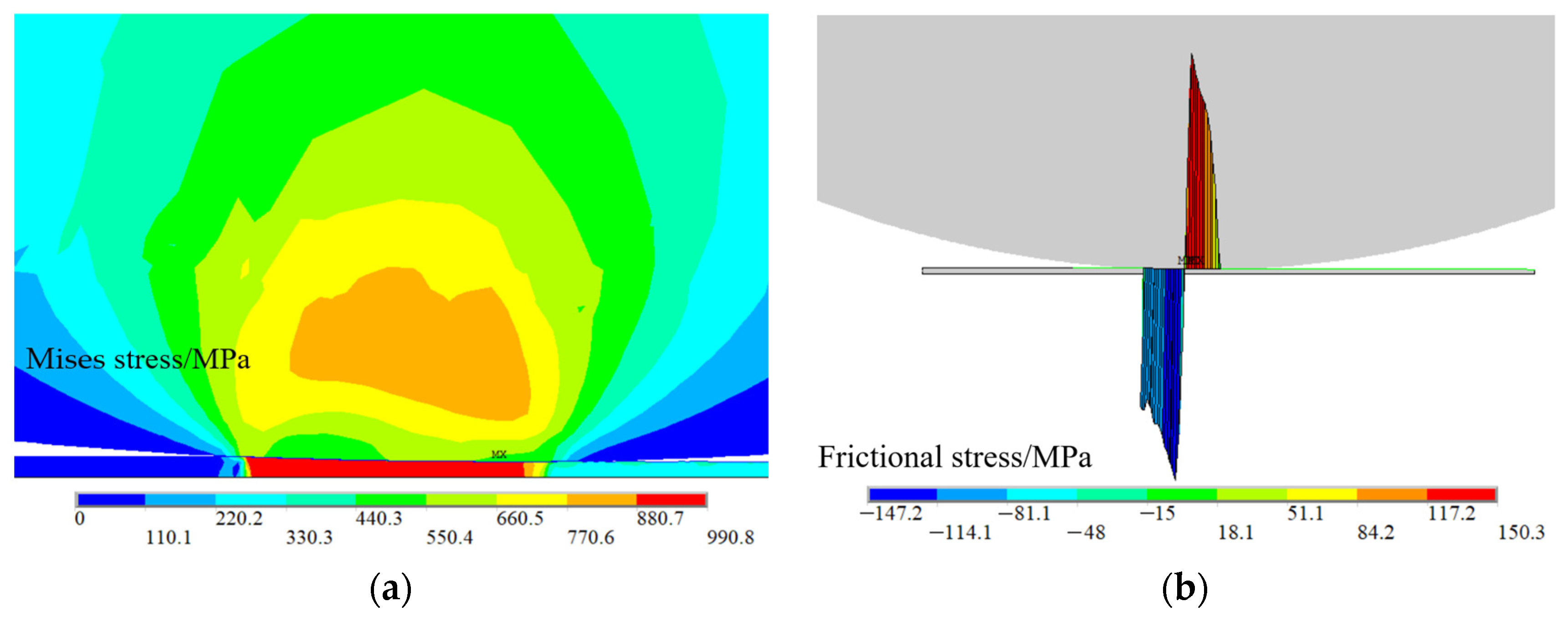
The displacement of the strip surface nodes perpendicular to the strip surface direction in the contact deformation zone is extracted under the stable rolling condition. According to the thickness direction, displacement distribution can reflect the roll profile in the contact deformation zone under different rolling processes. Figure 2a shows the cloud diagram of Mises stress between the roll and the rolled part during the rolling process, and Figure 2b shows the cloud diagram of friction stress distribution in the deformation zone of the rolled part. It can be seen that the friction stress in the deformation zone is divided into two parts since the neutral point, the friction stress at the exit, is positive, hindering the rolled parts from entering the roll gap, the part of the forward slip zone. The friction stress at the entrance is negative, which is the main force to pull the rolled parts into the roll seam, and this part is the back-slip zone.

2.2. Experimental Validation

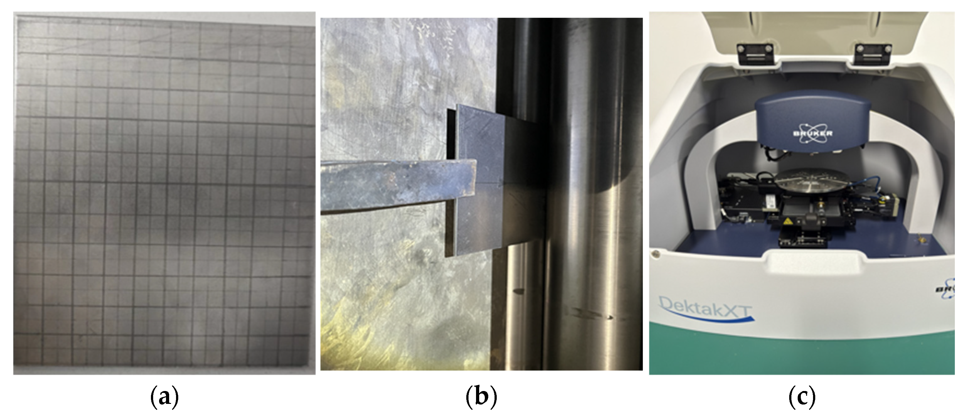
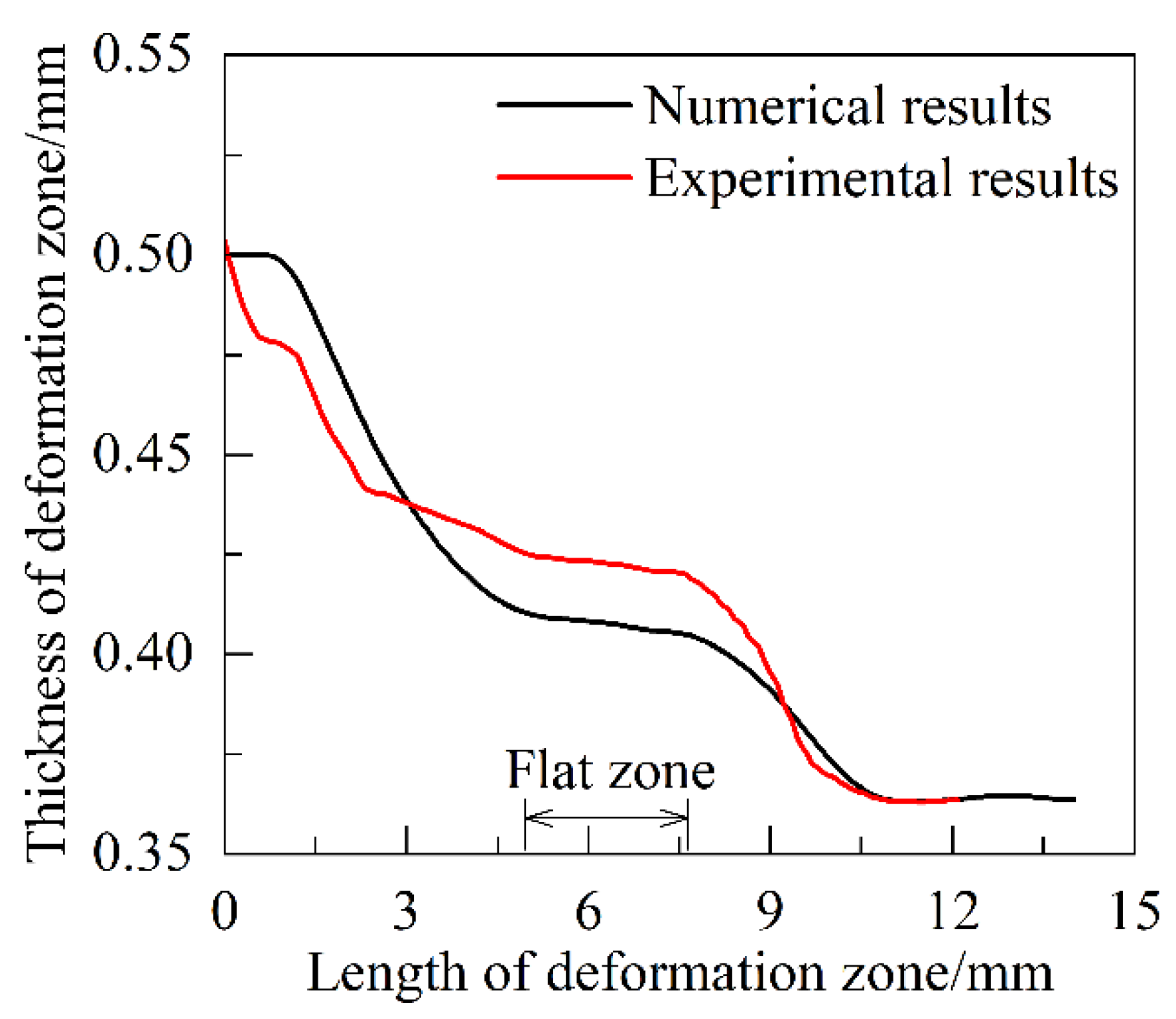
In order to verify the accuracy of the finite element model in calculating the deformation zone profile of the strip, ultra-high-strength steel rolling experiments were carried out. The experimental parameters are shown in Table 1. When rolling was stabilized, the rolls were lifted instantaneously to retain the deformation zone. The longitudinal surface coordinates of the deformation zone of the ultra-high-strength steel were collected using a probe-type profiler. The material and experimental setup are shown in Figure 3. During the measurement process, the table moves 0.25 mm each time, and the measurement is taken three times near each position, and the average value is taken to obtain the actual contour of the deformation zone. Figure 4 shows the comparison between the measured values and the numerical calculation results. It can be seen that the longitudinal distribution of the thickness of the deformation zone calculated using the finite element model is basically consistent with the experimental results, thus proving the accuracy of the model.
In order to verify the accuracy of the finite element model for the calculation of the forward slip, the rolling data in the rolling process of 1450 cold rolling mill of a steel mill is used as the experimental data, and some of its experimental data are shown in Table 2. The definition of forward slip is utilized to calculate the forward slip in the experimental data. And the established finite element model is used to numerically calculate the three working conditions in the table. The forward slip of the two is compared and analyzed. Table 3 shows the comparison between the experimental results and the results of the finite element model in terms of the forward slip value. It can be seen that the forward slip calculation results of the finite element model and the experimental forward slip value calculation results are relatively close to each other, and its error is within the acceptable range. This shows that the use of finite element model calculation of the forward slip problem has a high degree of accuracy and can be used to study the rule of change in the forward slip in the rolling process of UHSS. In addition, it should be noted that the error between the two increases with the decrease in the reduction ratio.

3. Results and Discussion

3.1. Analysis of Contact Arc Shape and Contact Stress in Deformation Zone

In order to analyze the effect of the rolling process parameters on the contact profile and contact positive stress distribution in the deformation zone during cold rolling of UHSS, rolling numerical simulation was carried out for different strip thicknesses, undercutting rates, friction coefficients, yield strengths, and tensile stresses. The contact profile and positive contact stress distribution in the deformation zone under different rolling process parameters were obtained. The set rolling process parameter variables are shown in Table 4, and other parameters are set with reference to Table 1.
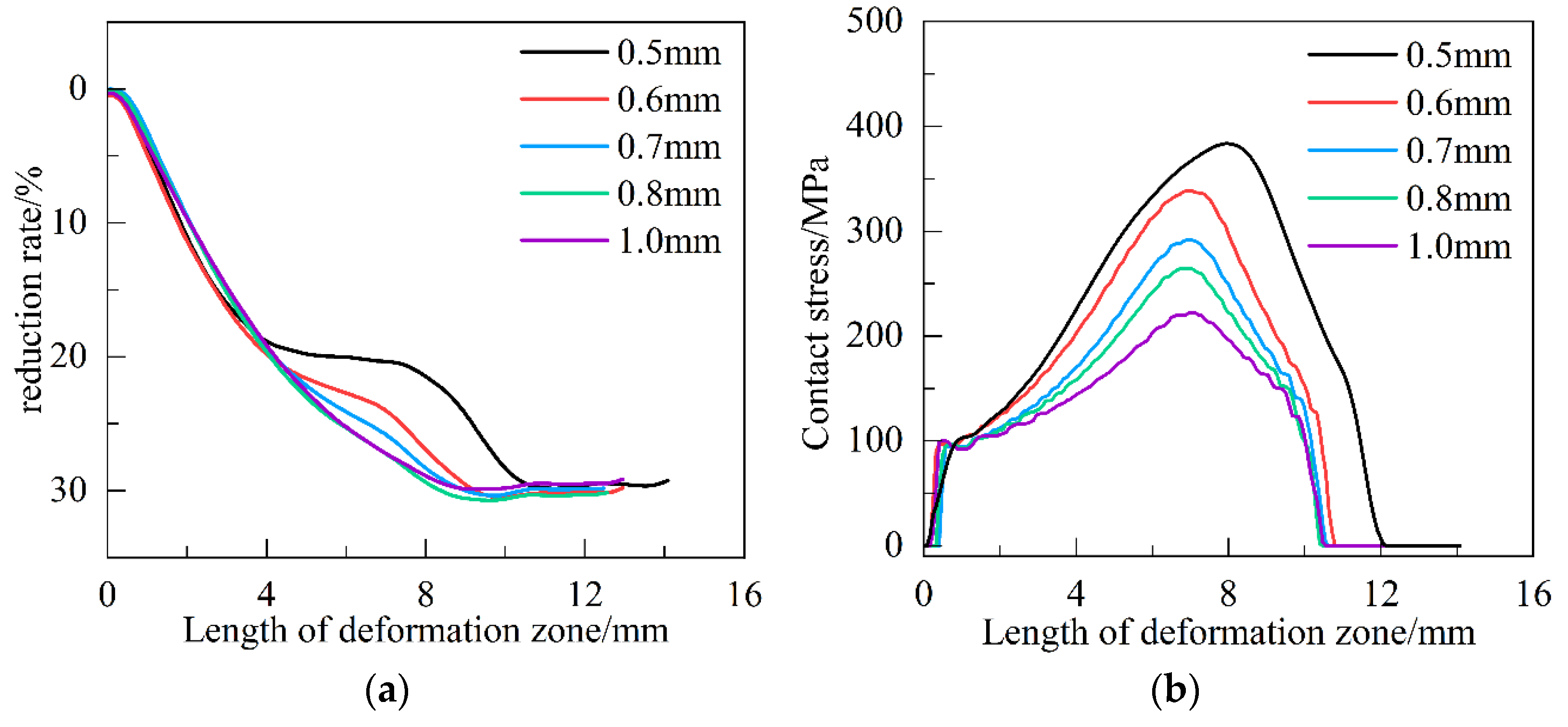
The thickness of the strip was set to 0.5, 0.6, 0.7, 0.8, and 1.0 mm, and the undercutting rate was 30%. Rolling numerical simulation was carried out to obtain the contact arc profile and contact stress distribution in the deformation zone under different strip thicknesses, as shown in Figure 5. For the convenience of presentation, the longitudinal coordinate of Figure 5a is plotted with the reduction ratio as the parameter. It can be seen that the rolling deformation zone grows gradually with the decreasing thickness of the strip under the control of the constant reduction ratio. The contact arc shape is gradually transformed from an approximate circular curve to a non-circular curve, and a neutral zone appears in the middle of the deformation zone. At a strip thickness of 1 mm, the contact arc in the strip deformation zone is approximately circular. At a strip thickness of 0.6 mm, the contour of the contact arc in the deformation zone starts to appear non-circular and a neutral zone begins to appear. When the plate thickness is thinned to 0.5 mm, a clear neutral zone appears in the middle of the deformation zone. The plastic deformation of the strip is mainly concentrated in the entrance and exit zones, and the amplitude of the rolled part under pressure in the central non-circular arc section is very small. As shown in Figure 5b, the increase in plate thickness leads to a gradual decrease in contact stress. The whole deformation zone is asymmetrically distributed about the centerline of the roll, which gradually expands to the exit of rolling along with the intensification of the degree of elastic flattening of the roll. The peak contact stress gradually shifts to the exit with the expansion of the neutral zone.
Numerical simulations were carried out after controlling the preset reduction ratio to 20%, 40%, 60%, and 80% to obtain the contact arc profile and contact stress distribution in the deformation zone under different reduction ratios, as shown in Figure 6. As shown in Figure 6a, with the increasing reduction ratio, the rolling deformation zone gradually grows, and the contact arc shape gradually changes from an approximate circular curve to a non-circular curve shape. At a preset downpressure rate of 80%, a distinct “flat zone”, or neutral zone, appears in the middle of the deformation zone. When the preset underpressure rate is 40%, the contact curve shape within the deformation zone is approximately circular, and there is no obvious neutral zone. Through comparison, it is found that the length of the neutral zone grows with the increase in the reduction ratio. The plastic deformation of the rolled part is mainly concentrated in the entrance and exit zones, and the magnitude of the rolled part under pressure in the central non-circular curve section is very small and is more significant with the increase in the reduction ratio. As shown in Figure 6b, it can be found that the deformation zone shows asymmetric distribution about the centerline of the roll. With the gradual increase in the amount of depression, the value of contact stress gradually increases, and the peak of contact stress gradually shifts to the exit.
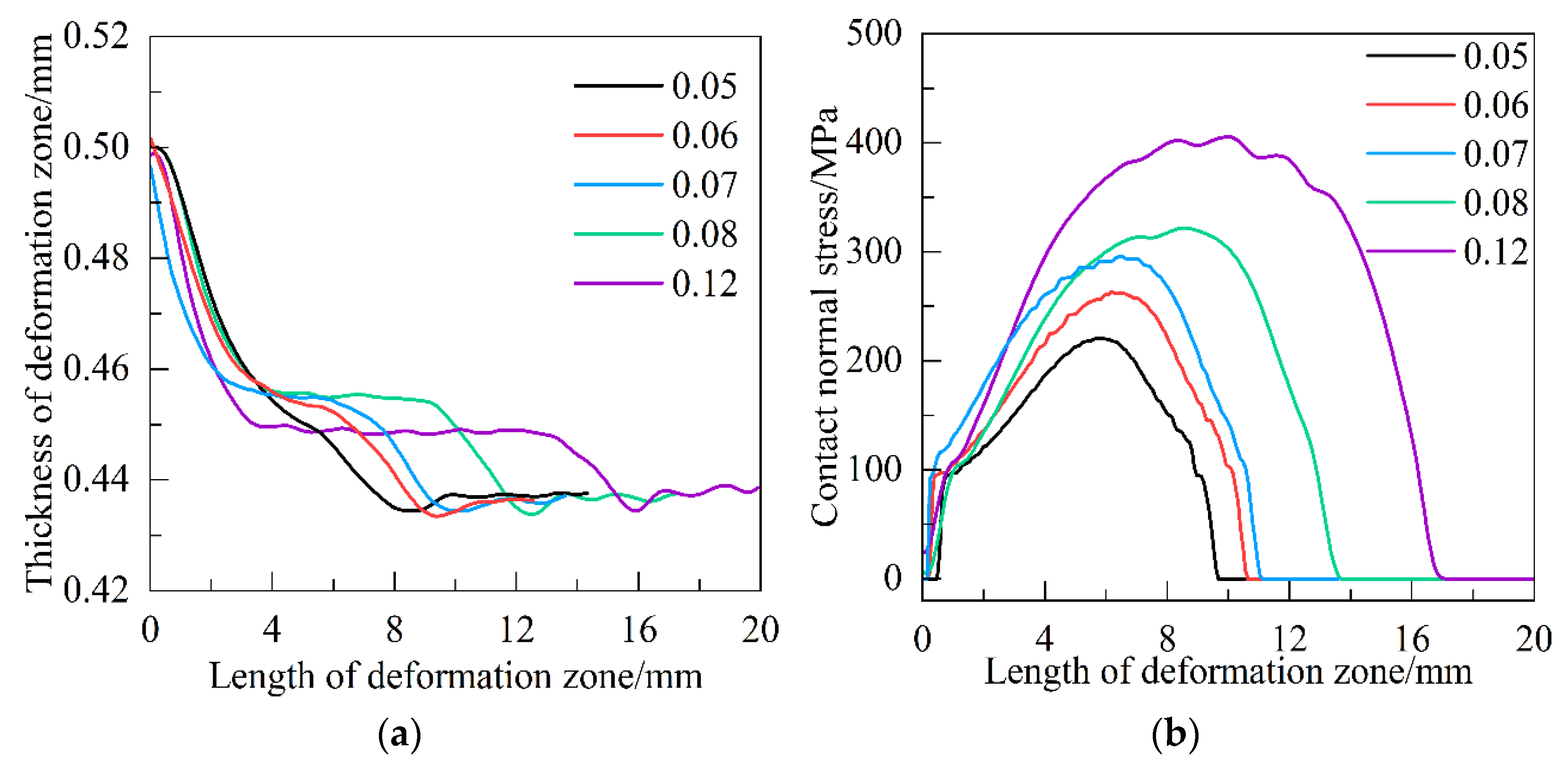
The friction coefficients between the strip and the roll were set to 0.05, 0.06, 0.07, 0.08, and 0.12 for numerical simulation, and the contact arc profile and contact stress distribution in the deformation zone under different friction coefficients were obtained, as shown in Figure 7. As shown in Figure 7a, it can be found that with the increase in the friction coefficient, the length of the rolling deformation zone grows gradually, and the contact arc shape between the roll and the rolled part is gradually transformed from a circular curve to a non-circular curve with an obvious neutral zone, and the neutral zone grows with the increase in the friction coefficient. When the friction coefficient increases from 0.05 to 0.12, the contact profile of the deformation zone goes from an approximate circular curve to the appearance of a neutral zone, and the neutral zone grows gradually. The critical friction coefficient for the significant change in the deformation zone profile is 0.06 to 0.07. When the friction coefficient is 0.12, the neutral zone accounts for nearly 50% of the whole deformation zone. As shown in Figure 7b, it can be found that as the friction coefficient increases, the contact stress between the roll and the rolled part increases, and the positive contact stress shows an approximate elliptical distribution in the center area.
The yield strength of the strip was set to 500, 600, 700, 800, and 960 MPa for numerical simulation, and the contact arc contour and contact stress distribution within the deformation zone of the rolling stabilization process of the strip with different yield strengths were obtained, as shown in Figure 8. As shown in Figure 8a, it is found that the length of the deformation zone grows as the yield strength of the strip increases. This is because as the yield strength increases, the required rolling force increases, the amount of roll flattening increases, and the length of the deformation zone becomes longer. When the yield strength increases from 500 MPa to 960 MPa, the deformation zone contact profile from the approximate circular curve to the emergence of a clear neutral zone of non-circular curve, and the neutral zone grow gradually. The critical yield strength that prompts the deformation zone contour to change significantly is 600~700 MPa. As shown in Figure 8b, the contact stress within the contact deformation zone increases correspondingly with the increase in yield strength. As the yield strength increases, the neutral point moves forward. The peak contact stress is gradually shifted from the inlet to the outlet along with the increase in the neutral zone.
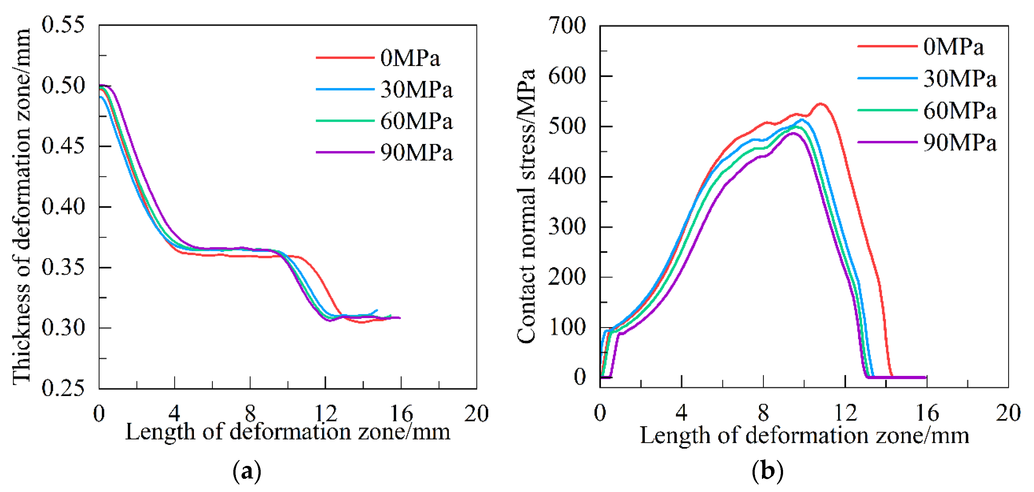
The strip tension stress is set to 0, 30, 60, and 90 MPa for numerical simulation, and the contact arc contour and contact stress distribution within the deformation zone of the strip rolling stabilization process under different tension stresses are obtained, as shown in Figure 9. As shown in Figure 9a, the length of the deformation zone decreases with the increase in the tensile stress, which is mainly due to the action of the tensile stress reducing the elastic recovery of the strip and making the length of the deformation zone shorter. When the tensile stress is 0 MPa, a longer neutral zone appears in the middle of the deformation zone. When the tensile stress is 90 MPa, the length of the neutral zone is reduced. As shown in Figure 9b, as the tensile stress increases, the contact stress decreases, the neutral point position gradually moves forward, and the peak contact stress gradually approaches the centerline of the roll. This is because the applied tensile stress leads to a reduction in the resistance to plastic deformation of the rolled part.

3.2. Calculation and Analysis of Forward Slip Within Deformation Zone

The elastic flattening effect of the working rolls directly affects the rolling deformation zone, which in turn affects the size of the front slip. Therefore, the rolls are setup as the elastic behavior body and rigid body, respectively, for comparative study. Using the constructed finite element model, numerical simulation is carried out for rigid roll and elastic roll under different roll diameters, friction coefficients, and yield strengths, and the influence laws of the three process parameters on the forward slip are obtained. The set rolling process parameter variables are shown in Table 5. The point in the rolling deformation zone where the frictional stress is zero is called the neutral point. Frictional stress is the shear stress on the contact interface between the roll and the strip. The friction stress is divided into two parts from the neutral point, and the area with positive friction stress corresponds to the forward slip area on the exit side of the roll.
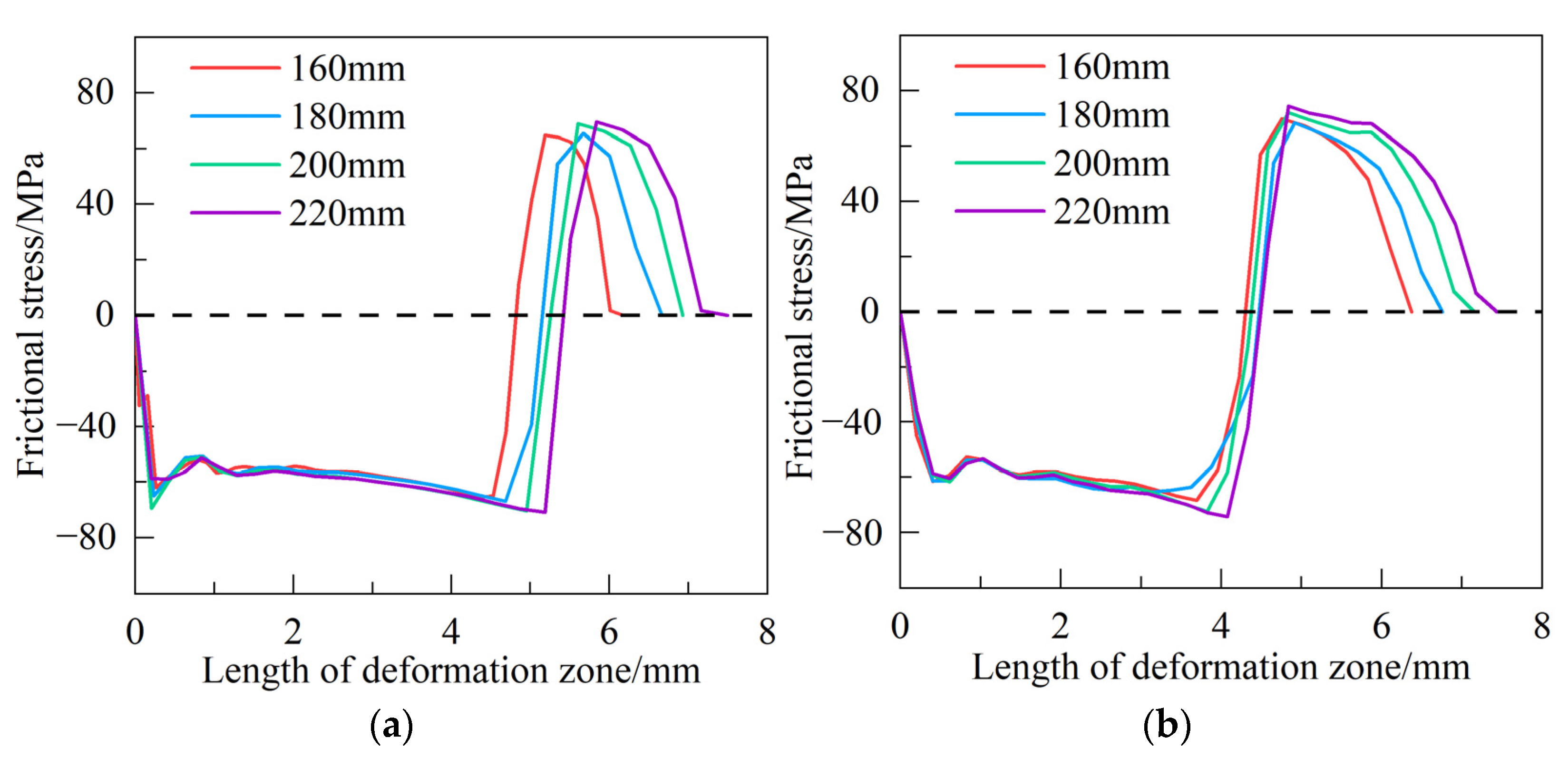
Set the strip initial thickness as 1 mm, the reduction ratio as 40%, the friction coefficient as 0.05, the roll diameter as 160, 180, 200, and 220 mm for the rolling numerical simulation to obtain the friction stress distribution in the deformation zone of the rolling under different roll diameters. As shown in Figure 10, as the roll diameter increases, the length of the deformation zone increases, and the neutral point gradually moves toward the rolling exit. However, the movement of the neutral point is smaller than the increase in the length of the deformation zone, so the forward slip increases. The forward movement of the neutral point of the rigid roll is larger than that of the elastic roll. Compared to Figure 10a,b, when the roll diameter is constant and the roll is converted from a rigid body to an elastic behavior body, the length of the deformation zone does not change significantly. The neutral point position moves relatively toward the rolling entrance and the forward slip increases.
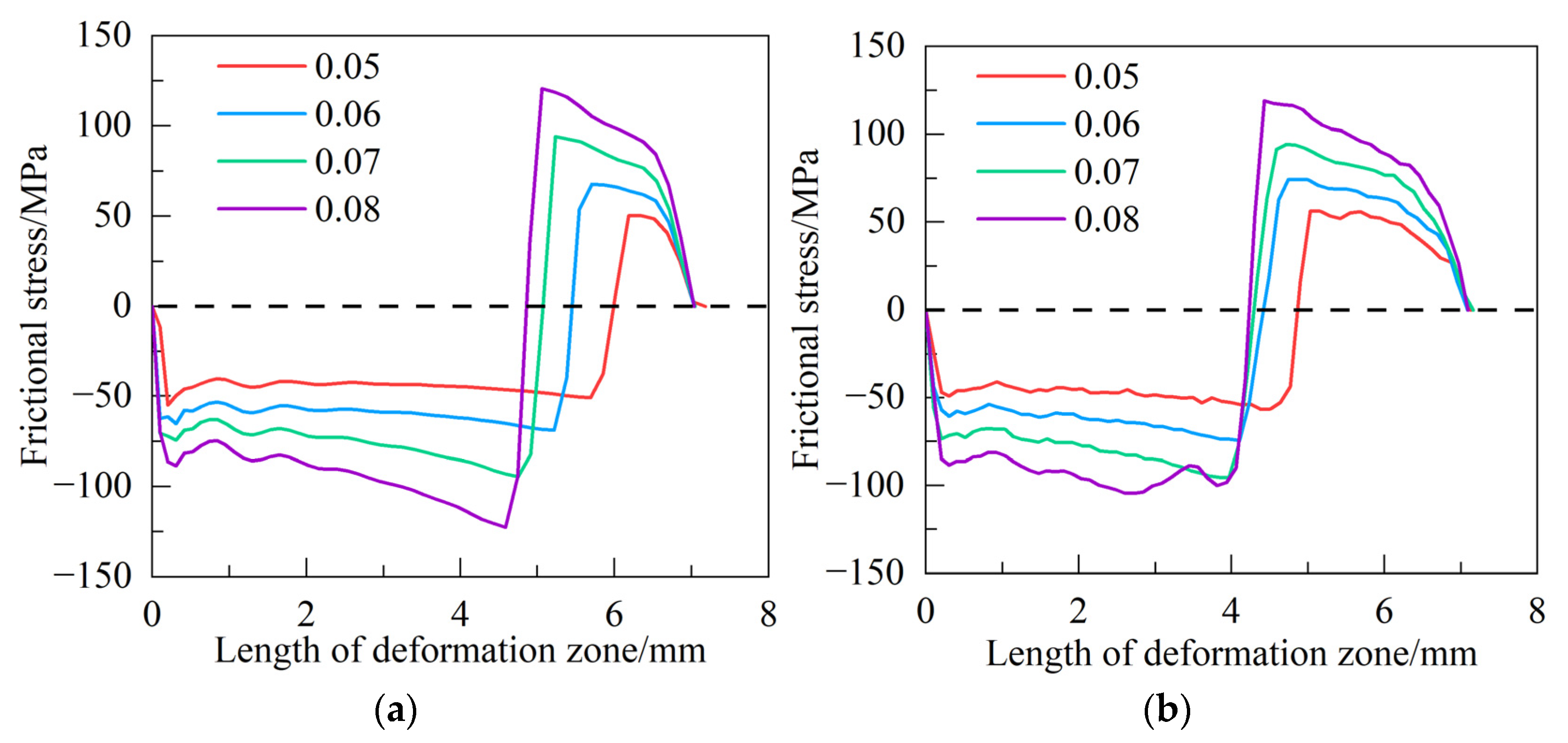
Set the strip thickness as 1 mm, the reduction ratio as 40%, the roll diameter as 200 mm, the friction coefficients as 0.05, 0.06, 0.07, and 0.08, and the numerical simulation of rolling is carried out to obtain the distribution of friction stress in the rolled deformation zone under different friction coefficients. As shown in Figure 11, as the friction coefficient increases, the length of the deformation zone of the rolled part is almost unchanged, the neutral point gradually moves toward the rolling inlet, and the forward slip increases. The backward shift in the neutral point of the elastic roll is smaller than that of the rigid roll. Compared to Figure 11a,b, when the friction coefficient is certain and the roll is converted from the rigid body to elastic behavior body, the length of the deformation zone does not change significantly. The neutral point position moves relatively toward the rolling entrance and the forward slip increases.
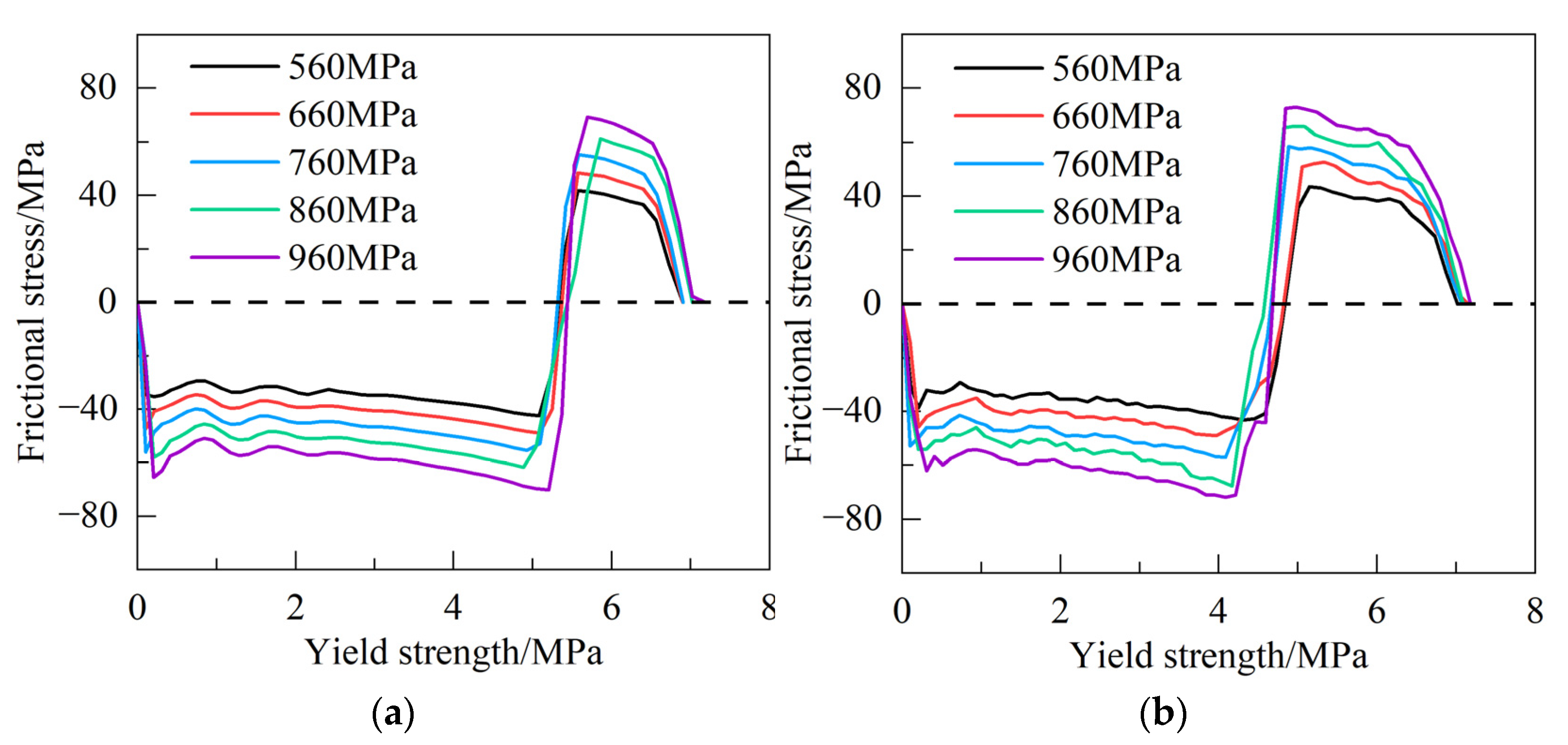
Set the strip thickness as 1 mm, the reduction ratio as 40%, the friction coefficient as 0.05, the roll diameter as 200 mm, and the yield strength of the strip steel as 560, 660, 760, 860, and 960 MPa for rolling numerical simulation to obtain the friction stress distribution in the rolling deformation zone under different yield strengths. As shown in Figure 12, with the increase in the yield strength of the rolled part, the absolute value of the friction stress in the deformation zone gradually increases, and the length of the deformation zone becomes longer. When the roll is a rigid body, the neutral point position changes very little. When the roll is an elastic roll, the neutral point position gradually moves toward the entrance as the yield strength increases and the forward slip increases. As compared to Figure 12a,b, when the yield strength is certain and the roll is converted from a rigid roll to an elastic roll, the forward slip increases. The value of friction stress within the deformation zone and the length of the deformation zone do not change significantly.
By normalizing the above data, the curve distribution of the forward slip value within the deformation zone is obtained, as shown in Figure 13. As shown in Figure 13a–c, when the roll diameter, friction coefficient, and strip yield strength increase, the forward slip within the deformation zone increases. When the roll is transformed from a rigid body to an elastic behavior body, the forward slip is elevated by about 1.5 times.

4. Conclusions

  • The finite element simulation model of ultra-high-strength steel rolling was established and experimentally verified. By analyzing the reasons for the emergence of the “neutral zone”, it was found that the plastic deformation of the rolled parts is mainly concentrated in the entrance and exit zones and the magnitude of the rolled parts in the neutral zone is very small. The deformation zone is asymmetrically distributed about the centerline of the roll. The peak contact stress in the deformation zone is accompanied by the intensification of the degree of elastic compression of the rolls and it gradually expands to the exit of the rolling.
  • With the increase in roll diameter, the deformation zone length increases, the neutral point gradually moves to the exit, and the movement of the neutral point is smaller than the increase in the deformation zone length. The increase in friction coefficient and yield strength has less influence on the length of rolling deformation zone, but the neutral point gradually moves to the entrance, so the forward slip becomes larger. For the yield strength of 960 MPa ultra-high-strength steel, the critical friction coefficient range of the neutral zone in the deformation zone of the rolling process is 0.05~0.08, and the critical yield strength of the neutral zone of the strip is 600~700 MPa.
  • With the increase in reduction ratio, the roll diameter, friction coefficient, and yield strength of the rolled parts decrease, the value of the forward slip of the rolled deformation zone decreases. When the roll is converted from a rigid body to an elastic behavior body, the length of the deformation zone does not change significantly, the neutral point position moves relative to the entrance of the rolling, and the forward slip increases.

Author Contributions

Conceptualization: J.W.; data curation, Z.B. and Y.G.; formal analysis: J.W., Z.S. and Y.G.; methodology: Z.B. and X.L.; validation: Z.G., J.W. and X.L.; writing—original draft: J.W.; writing—review and editing: Y.G., Z.G. and Z.S. All authors have read and agreed to the published version of the manuscript.

Funding

This research was supported by the Hebei Natural Science Foundation (E2024203125), the Science Research Project of Hebei Education Department (CXY2023012), the S&T Program of Hebei (23280101Z), and the S&T Program of Hebei (22281001Z).

Data Availability Statement

The original contributions presented in this study are included in the article. Further inquiries can be directed to the corresponding author.

Conflicts of Interest

The authors declare no conflicts of interest.

References

  1. Tang, W.J.; Jin, X.Y.; Hu, G.K. Internal oxidation of hot-rolled ultra-high strength steel and its effect on the surface quality of cold-rolled sheets. Baosteel Tech. Res. 2021, 15, 1–8. [Google Scholar]
  2. Yang, L.; Yin, F.; Wang, J. Local buckling resistances of cold-formed high-strength steel SHS and RHS with varying corner radius. Thin Walled Struct. 2022, 172, 108909. [Google Scholar] [CrossRef]
  3. Li, J.H.; Zhang, D.P.; Jiang, Z.H. Progress on improving strength-toughness of ultra-high strength martensitic steels for aerospace applications: A review. J. Mater. Res. Technol. 2023, 23, 172–190. [Google Scholar] [CrossRef]
  4. Zhao, Z.Z.; Chen, W.G.; Gao, P.F. Progress and perspective of advanced high strength automotive steel. J. Iron Steel Res. 2020, 32, 1059–1076. [Google Scholar]
  5. He, A.R.; Liu, C.; Shao, J. Research progress and application of new advanced and intelligent rolling technologies for hot rolled strip. J. Steel Roll. 2024, 41, 38–50. [Google Scholar]
  6. Li, G.Y.; Wang, L.; Ma, M.T. Development of 3rd generation advanced high strength steel for automotive. Steel Roll 2019, 36, 1–13. [Google Scholar]
  7. Cao, J.G.; Jiang, J.; Qiu, L. High precision integrated profile and flatness control for new-generation high-tech wide strip cold rolling mills. J. Cent. South Univ. Sci. Technol. 2019, 50, 1584–1591. [Google Scholar]
  8. Huang, Q.X. Research Progress on Key Equipment and Technology of High Quality Steel Plate and Strip Rolling. J. Mech. Eng. 2023, 59, 34–63. [Google Scholar]
  9. Zhang, K.; Liu, P.; Li, W. High Strength-Ductility Nb-microalloyed Low Martensitic Carbon Steel:Novel Process and Mechanism. Acta Metall. (Engl. Lett.) 2015, 28, 1264–1271. [Google Scholar] [CrossRef]
  10. Kim, D.H.; Kang, J.; Gwon, H. Counter-balancing effects of Si on C partitioning and stacking fault energy of austenite in 10Mn quenching and partitioning steel. J. Mater. Sci. Technol. 2022, 98, 248–257. [Google Scholar] [CrossRef]
  11. Chen, Y.; Zhang, H.Z.; Tang, J.J. Integrated Modelling of Microstructure Evolution and Mechanical Properties Prediction for Q&P Hot Stamping Process of Ultra-High Strength Steel. Chin. J. Mech Eng. 2020, 33, 168–181. [Google Scholar]
  12. Jiang, J.; Wu, M.; Xu, T.T. Study on impact toughness of TMCP and quenched and tempered high strength steels. Case Stud. Constr. Mater. 2024, 20, e02795. [Google Scholar] [CrossRef]
  13. Ren, Z.K.; Wang, T.; Wang, Y.L. Analysis of contact contour and contact pressure in deformation zone of ultra-thin strip rolling. Iron Steel 2018, 53, 62–68. [Google Scholar]
  14. Luo, D.X.; Chen, Q.A.; Liu, L.W. Deformation Analysis in Deformation Zone during Asymmetric Rolling with Different Friction Coefficient. J. Iron Steel. Res. 2004, 16, 42–45. [Google Scholar]
  15. Han, G.M.; Li, H.B.; Yan, D.J. A mathematical model for longitudinal temperature evolution in strip deformation zone during cold rolling. Int. J. Term. Sci. 2023, 192, 108462. [Google Scholar] [CrossRef]
  16. Shigaki, Y.; Nakhoul, R.; Montmitonnet, P. Numerical Treatments of Slipping/No-Slip Zones in Cold Rolling of Thin Sheets with Heavy Roll Deformation. Lubricants 2015, 3, 113–131. [Google Scholar] [CrossRef]
  17. Yu, W.; Sun, G.J.; Shen, S. Forward slip theoretical model and simulation for variable gauge rolling of TRB sheet. Chin. J. Eng. 2014, 36, 241–245. [Google Scholar]
  18. Li, S.G.; Jia, D.P.; Mao, Z.Z. Finite Element Simulation Analysis of Thin Strip Rolling Process. Metall. Equip. 2022, 3, 44–49+102. [Google Scholar]
  19. Jiang, Z.Y.; Tieu, A.K.; Lu, C. A FEM modelling of the elastic deformation zones in flat rolling. J. Mater. Process. Technol. 2004, 146, 167–174. [Google Scholar] [CrossRef]
  20. Bu, H.; Yan, Z.; Zhang, D. A novel approach to improve the computing accuracy of rolling force and forward slip. Ironmak. Steelmak. 2019, 46, 269–276. [Google Scholar] [CrossRef]
  21. Shimura, M.; Kasai, D.; Otsuka, T. Mechanisms of Slip Generation in Cold Rolling of AHSS: Regular Article. ISIJ Int. 2023, 63, 2033–2041. [Google Scholar] [CrossRef]
  22. Bu, H.N.; Yan, Z.W.; Zhang, D.H. Comprehensive adaptation of rolling force model and forward slip model in tandem cold rolling process control. J. Shenyang Univ. Technol. 2015, 37, 299–303. [Google Scholar]
  23. Nam, Y.S.; Zamanian, A.; Shin, J.T. A Novel On-Line Model for the Prediction of Strip Profile in Cold Rolling. ISIJ Int. 2019, 60, 308–317. [Google Scholar] [CrossRef]
  24. Liu, Y.; Gu, Q.; Zhang, W. Improved model for calculating rolling load of ultra-high strength steel in cold rolling process. Iron Steel 2021, 56, 108–116. [Google Scholar]
  25. Máté, S.; György, K.; Lenard, J.G. The Difficulties of Predicting the Coefficient of Friction in Cold Flat Rolling. J. Tribol. 2021, 143, 101703. [Google Scholar] [CrossRef]
  26. Jeswiet, J. A comparison of friction coefficients in cold rolling. J. Mater. Process. Technol. 1998, 80, 239–244. [Google Scholar] [CrossRef]
  27. Meng, Y.J. Basic Knowledge of Steel Rolling, 1st ed.; Metallurgical Industry Press: Beijing, China, 2005; pp. 229–243. [Google Scholar]
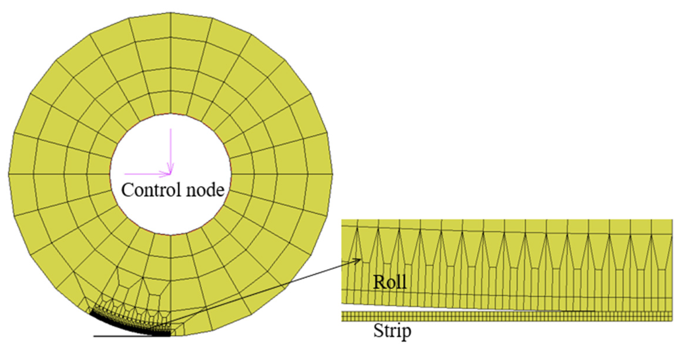
Figure 1. Two-dimensional finite element modeling of UHSS cold rolling.
Metals 15 00311 g001
Figure 2. Finite element modeling results. (a) Mises stress cloud during rolling process. (b) Friction stress cloud within deformation zone.
Metals 15 00311 g002
Figure 3. Materials and experimental equipment. (a) Ultra-high-strength steel plate; (b) steel rolling mill; (c) surface profile gauge.
Metals 15 00311 g003
Figure 4. Comparison of contours of rolled deformation zones.
Metals 15 00311 g004
Figure 5. Contact profile and contact stress distribution in deformation zone for different strip thicknesses. (a) Contact profile of deformation zone; (b) contact stress in deformation zone.
Metals 15 00311 g005
Figure 6. Contact profile and contact stress distribution in deformation zone under different indentation rates. (a) Contact profile of deformation zone; (b) contact stress in deformation zone.
Metals 15 00311 g006
Figure 7. Contact profile and contact stress distribution in deformation zone with different friction coefficients. (a) Contact profile of deformation zone; (b) contact stress in deformation zone.
Metals 15 00311 g007
Figure 8. Contact profile and contact stress distribution in deformation zone at different yield strengths. (a) Contact profile of deformation zone; (b) contact stress in deformation zone.
Metals 15 00311 g008
Figure 9. Contact profile and contact stress distribution in deformation zone under different tensile stresses. (a) Contact profile of deformation zone; (b) contact stress in deformation zone.
Metals 15 00311 g009
Figure 10. Distribution of friction stress in rolling deformation zone under different roll diameters. (a) Rigid roller; (b) elastic roller.
Metals 15 00311 g010
Figure 11. Distribution of frictional stresses in rolled deformation zone under different friction coefficients. (a) Rigid roller; (b) elastic roller.
Metals 15 00311 g011
Figure 12. Distribution of frictional stresses in rolled deformation zone at different yield strengths. (a) Rigid roller; (b) elastic roller.
Metals 15 00311 g012
Figure 13. Change in forward slip value within rolled deformation zone. (a) Roll diameter; (b) friction coefficient; (c) yield strength.
Metals 15 00311 g013
Table 1. Parameters of finite element simulation model.
ParametersValue
Work roll diameter (mm)400
Modulus of elasticity (MPa)210,000
Poisson’s ratio0.3
Strip inlet thickness (mm)0.5
Strip outlet thickness (mm)0.36
Strip yield strength (MPa)960
Friction coefficient0.05
Table 2. Actual rolling parameters at steel mill high-strength steel production site.
Rolling ParametersExperiment 1Experiment 2Experiment 3
Inlet thickness (mm)2.01.61.3
Outlet thickness (mm)1.61.31.1
Deformation resistance (MPa)1161.71171.81266.7
Work roll diameter (mm)400400400
Rolling speed (m/min)190.8250.0301.8
Strip export speed (m/min)249.8301.5353.4
Friction coefficient0.050.030.03
Rolling force (kN)1573.61423.01395.5
Table 3. Comparison of forward slip error between finite element simulation results and experimental results.
NumberExperimental Results/%Simulation Results/%Relative Error/%
130.930.41.6
220.823.08.2
317.118.79.4
Table 4. Rolling process parameter variables.
Process Parameter VariablesValue
Initial strip thickness (mm)0.5, 0.6, 0.7, 0.8, 1.0
Reduction ratio (%)20, 40, 60, 80
Friction coefficient0.05, 0.06, 0.07, 0.08, 0.12
Yield strength (MPa)500, 600, 700, 800, 960
Tension (MPa)0, 30, 60, 90
Table 5. Rolling process parameter variables.
Process Parameter VariablesValue
Roll diameter (mm)160, 180, 200, 220
Friction coefficient0.05, 0.06, 0.07, 0.08
Yield strength (MPa)560, 660, 760, 860, 960
Disclaimer/Publisher’s Note: The statements, opinions and data contained in all publications are solely those of the individual author(s) and contributor(s) and not of MDPI and/or the editor(s). MDPI and/or the editor(s) disclaim responsibility for any injury to people or property resulting from any ideas, methods, instructions or products referred to in the content.