Article

Fluid Dynamics Analysis of Coherent Jet with a Mixed Shrouding H2-CO2/N2 for EAF Steelmaking

1
National Center for Materials Service Safety, University of Science and Technology Beijing, Beijing 100083, China
2
Institute for Carbon Neutrality, University of Science and Technology Beijing, Beijing 100083, China
3
Institute of Steel Sustainable Technology, Liaoning Academy of Materials, Shenyang 110167, China
*
Authors to whom correspondence should be addressed.
Metals 2025, 15(3), 291; https://doi.org/10.3390/met15030291
Submission received: 8 February 2025 / Revised: 5 March 2025 / Accepted: 6 March 2025 / Published: 7 March 2025
(This article belongs to the Special Issue Advanced Metal Smelting Technology and Prospects)

Abstract

:
In order to suppress the rapid combustion effect and consumption rate of pure hydrogen gas, N2 or CO2 at flow rates of 0, 80, and 240 Nm3/h was pre-mixed with shrouding H2 at flow rates of 800, 720, and 560 Nm3/h at room temperature, and the behaviors of the main oxygen jet and shrouding flame were analyzed by both numerical simulation and combustion experiments. The results showed that, because of the participation of CO2 in the H2 combustion reaction, the length of the axial velocity potential core was reduced using the CO2 shrouding mixed injection method, compared to the same mixed rate of N2. This trend would be further enhanced as N2 and CO2 mixing ratio increased. Meanwhile, when the shrouding mixed rate is 30%, the maximum axial and radial expansion rate generated by N2-H2 shrouding method is 1.28 and 1.04 times longer than that by the CO2-H2 shrouding method. The Fo-a, theoretical impaction depth and area generated by the 10% N2 shrouding mixed rate was 84.0, 95.5 and 86.4% of those generated by the traditional coherent jet, respectively, which indicated that the 10% N2 shrouding mixed rate method might lead to comparable production indexes in the EAF steelmaking process.

1. Introduction

In comparison to the structure of the Basic Oxygen Furnace (BOF), a flat structure is applied in the Electrical Arc Furnace (EAF), which is designed to ease the process of changing scrap steel, providing a three-phase electrode supply, and enabling the tapping of molten steel [1,2,3,4]. This indicates that the top-blowing oxygen supplement for the BOF steelmaking process is not directly used in the EAF steelmaking process. Therefore, the EAF steelmaking process has adopted the side-blowing method with multiple oxygen lances to enhance the dynamic conditions and mass transfer rate in the molten bath. In order to further improve the impaction ability and utilization rate of the oxygen supersonic jet, a shrouding combustion technology utilizing gas or liquid fuel has been developed and extensively applied in the EAF steelmaking process, known as coherent lance technology [5,6,7].
Many previous studies have focused on optimizing geometric structure and operational methods for coherent lance technology. Yamaguchi et al. [8] highlighted the advantages of using a coherent lance structure for heating low-temperature steel scrap and providing kinetic energy, in contrast to the traditional supersonic lance structure. Tian et al. [9] investigated the influence of various lime powder injection rates and central nozzle diameters on the flow field of the coherent jet. Wei et al. [10] proposed a mathematical model to describe the relationship between the operational conditions, such as lance height, design velocity, and the exit diameter of the Laval nozzle, and the impaction depth of the molten bath generated by the coherent jet. Jung et al. [11] presented a new jet-burner technology for coherent lance, which effectively reduced splashing and disturbance of electric arcs during melting, as demonstrated in a small-sized EAF.
The only byproduct of hydrogen combustion is water, rendering it a zero-emission energy source. Concurrently, hydrogen energy has the potential to diversify the energy portfolio and reduce reliance on fossil fuels. These characteristics position hydrogen energy as a pivotal solution for decreasing greenhouse gas emissions and improving air quality [12,13,14,15]. This implies that the shrouding fuel gas can be composed entirely of green H2, allowing for a 100% volume fraction. Feng et al. [16] introduced the different behavior of the coherent jet generated by H2 and CH4 shrouding gas and pointed out that the heat utilization of H2 shrouding gas was suppressed due to its higher combustion rate. Mahoney et al. [17] highlighted the critical role of H2 in coherent lance technology and demonstrated that employing H2 in the coherent lance could accelerate the decarburization rate and enhance the effectiveness of slag-metal stirring in the EAF steelmaking process.
Although a coherent lance using H2 is beneficial for enhancement of the technical and economical index in the EAF steelmaking process, low-cost and large-scale production of green H2 is still a great challenge. Previous studies have indicated that employing the N2-CH4 mixed shrouding injection method can lead to comparable production indexes in the EAF steelmaking process, as demonstrated through a series of industrial application tests [18].
To enhance the utilization rate of H2 and reduce its consumption, the effect of the mixed shrouding injection method on the flow field of the coherent jet has been investigated in this paper. Based on the physicochemical properties of N2 and CO2, N2 is considered an inert gas, signifying that no intermediate products are formed by the reaction of N2 with H2. In contrast, CO2 actively participates in the combustion reaction of H2, leading to the formation of unstable compounds, like OH, CO and HCO, in a very brief timespan [19,20,21]. Therefore, both the N2-H2 and CO2-H2 mixed shrouding injection methods have been analyzed by numerical simulation and combustion experiments in this research, to determine a suitable mixed shrouding injection method for the coherent lance method.
In this paper, Section 2 presents the coherent lance structure, illustrating the arrangement of the shrouding nozzles and providing a brief introduction to the combustion experiment. Section 3 outlines the detailed conditions of the numerical model. Subsequently, the axial velocity, total temperature, theoretical impaction cavity shape and the effective oxygen flow rate achieved by the simulation model are intensively investigated in Section 4.1, Section 4.2 and Section 4.3. Finally, Section 5 concludes the research by presenting the main findings.

2. Coherent Lance and Experimental System

According to the operational conditions of the 120 t EAF, the design Mach number and the main oxygen flow rate of the coherent lance (Keda Machinery Manufacturing Co., Ltd., Bazhou, Hebei, China) were determined to be 2.20 and 2500 Nm3/h, respectively. The throat and exit radiuses of the main Laval nozzle, calculated by one-dimensional iso-entropic flow theory, were 11.1 and 15.7 mm, respectively.
In this research, the shrouding nozzle structure was designed as a three concentric rings arrangement, their radiuses from the inner to the outer concentric ring being 34.0, 49.5, and 64.0 mm, respectively, as shown in Figure 1. Moreover, the hydraulic radiuses of the inner, intermediate and outer shrouding nozzles were 4.4, 5.6 and 6.8 mm, respectively, and there were 10 shrouding nozzles at each concentric ring.
Table 1 presents the details of the operational conditions of the combustion experiment. Three mixed types have been selected, which were 0, 10 and 30% volume fractions of the design H2 shrouding flow rate. Thus, the CO2 and N2 mixed flow rates were set at 0, 80 and 240 Nm3/h, respectively, while the H2 shrouding flow rates were 800, 720 and 560 Nm3/h, respectively. Additionally, the O2 shrouding flow rate was set at half that of the H2 shrouding flow rate.
Both inner and outer shrouding nozzles are used to transport oxygen, and the shrouding fuel gas was injected by the intermediate shrouding nozzle. The same parameters for the coherent lance were used in both the numerical simulations and combustion experiments. This indicated that both numerical simulation and combustion experiments were carried out with a full-scale coherent lance.
In this research, a series of combustion experiments was conducted in a high-temperature combustion furnace (Keda Machinery Manufacturing Co., Ltd., Bazhou, Hebei, China), as depicted in Figure 2. In the preparation stage, the burner was ignited to improve the ambient temperature of experimental furnace, and 12 thermocouples were fixed at different locations of the furnace side-wall, as shown in Figure 2a,b.
When the ambient temperature reached 1700 K, the burner was extinguished. The Pitot tube was initially positioned at specific axial locations to measure the dynamic and static pressures of the coherent jet along the centerline of the Laval nozzle. Subsequently, a thermocouple was placed at the same locations in order to measure the total temperature of the coherent jet. Finally, a hollow tube replaced the thermocouple to measure the gas content. Based on the pressure, temperature and gas content, the axial velocity of the coherent jet was calculated by Equations (1)–(3), following [22].
V = 2 γ R T γ 1 P d P s ( γ 1 ) / γ 1 ,   Ma   >   0.3 ,
V = 2 ( P t P s ) ρ ,   Ma     0.3 ,
γ = i = 1 n ( γ i × m f i )
The pressure, temperature, and oxygen mass fraction of the coherent jet were measured continuously for 10 s. Combustion experiments under each operational condition were conducted three times. After calculating the average values of these measurements, they were compared with the simulation results to evaluate the accuracy of the numerical model. In previous literature [10,16,18], the measurement method and experimental system details have been reported and are only briefly mentioned here.

3. Numerical Model

To leverage the symmetry of the simulation model and reduce computational costs, only one-quarter of the geometry was used. A three-dimensional (3D) grid comprising 3.38 million hexahedral cells was then constructed. A Laval nozzle, comprising contraction, throat, and expansion sections, was constructed. Additionally, shrouding nozzles with a length of 100 mm were also incorporated into the simulation model. The high-velocity jet region extends from the tip of the main Laval nozzle to a distance of 2100 mm downstream in the axial direction and 400 mm in the radial direction, as illustrated in Figure 3a.
Figure 3b depicts the grid distribution of the numerical model with boundary conditions. The mass flow inlet was used at the main Laval and shrouding nozzle inlet (blue plane). The pressure outlet was adopted for the other computational domain boundaries (red plane). A non-slip condition was implemented at the coherent lance wall (gray plane) for the wall boundary condition.
Hereafter, the operational condition of the coherent lance was addressed by the shrouding gas flow rate and type. For instance, “H720-N80” represented that the flow rates of the H2 and N2 shrouding gas were 720 and 80 Nm3/h, respectively. Moreover, “H560-C240” represented that the flow rates of the H2 and CO2 shrouding gas were 560 and 240 Nm3/h, respectively. The traditional supersonic jet generated by the coherent lance without any shrouding gas was abbreviated as “TRA”. In all simulation scenarios, the oxygen flow rate through the main Laval nozzle was consistently set at 2500 Nm3/h.
In this paper, the all-zone initialization method was utilized. The x-velocity, y-velocity, and z-velocity were all set to 0 m/s This indicates that the computational domain began without any gas flow through the Laval or shrouding nozzle and was initially filled solely with static air.
The flow field of the coherent jet was simulated in this research using the commercial CFD software FLUENT 2020 R2 (ANSYS, Inc., Pittsburgh, PA, USA). In order to achieve an accurate simulation result, the SST k-ω turbulence model was used to compute the flow dynamics of the coherent jet, which combined the advantages of both the standard k-ε model and standard k-ω model.
The mass flow inlet and pressure outlet were designated as the boundary conditions for the inlet and outlet, respectively. To obtain more accurate results, specifications for intensity and hydraulic diameter were applied. Additionally, the initial turbulent intensity and backflow turbulent intensity values at the inlet and outlet boundary conditions were set at 3.0% and 5.5%, respectively.
The reactants produced by the fuel gas and oxygen underwent chemical reactions in a boundary zone and at a chemical scale, which was comparable to the turbulent mixing scale, based on the operating condition of the coherent lance. Thus, the EDC (Eddy-Dissipation Concept) model was selected for the interactions between turbulent flow and chemistry process, which was determined to be suitable for simulating shrouding combustion in previous studies. During the combustion process among H2, O2 and CO2, a large amount of unstable intermediate products, such as CHO, CH and HO, would be formed. In order to accurately simulate this process, the detailed chemical kinetic mechanism (GRI-Mech 3.0) was adopted in this research.
The simulation cases were conducted in the steady-state solution mode using a coupled algorithm to solve the governing equations with a second-order discretization mechanism. In addition, the solution converged when the following criterion was satisfied: The average total temperature and velocity variations at the outlet of computational domain were kept within 2.0 K and 1.0 m/s, respectively. The simulations were all conducted using a workstation equipped with a 192-core CPU and 240 GB of memory.

4. Results and Discussion

4.1. Axial Velocity Distribution

Figure 4 presents the axial velocity profiles of the main oxygen jet using different fuel mixed injection methods at the centerline of the Laval nozzle. For further understanding of the effect of the fuel mixed injection method on the flow field of the main oxygen jet, both the coherent jet with an H2 flow rate of 800 Nm3/h and the traditional supersonic jet are included in Figure 4a,b. This means that both simulation result and experimental data for H800 are consistent in Figure 4a,b, which is also the case for TRA.
The various lines (solid and dotted lines) and symbols (□, ○, △ and ▽) represent the simulation and the result measurement data for the combustion experiment, respectively, in Figure 4.
It is crucial to recognize that maintaining a stable flow rate requires real-time adjustments to the valve system for gas supplementation. During this process, the measured velocity value of the main oxygen jet exhibits continuous fluctuations within a defined range. The measurement data presented in Figure 4 represent only the average velocity calculated from the combustion experiment, as described in Section 2. Based on the experimental records, the observed deviation in the measured velocity value is ±6.2% of the average velocity.
Based on the result, the average axial velocity variation of the main oxygen jet at the centerline of the Laval nozzle between the experimental test and numerical simulation is about 4.3%, which proves that the experimental data is in good agreement with the simulation result. Thus, the numerical model built in this research can be adopted to accurately simulate the flow field of the coherent jet.
The results indicate that the shock wave first forms at the main Laval nozzle exit. Subsequently, the axial velocity potential core of the main oxygen jet is generated, due to its consistent axial velocity value. Finally, as the main oxygen jet reaches the end of the axial velocity potential core, its axial velocity continues to decrease. Based on the result, the initial axial velocities of the coherent jets at the Laval nozzle exit are the same at 499.5 m/s for all the operational conditions of the shrouding fuel mixed method. Hence, the shrouding fuel mixed method has no effect on the initial axial velocity of the main oxygen jet at the Laval nozzle exit.
The axial velocity potential core length of the main oxygen jet generated by H720-N80, H720-C80, H560-N240 and H560-C240 was 1.03, 1.01, 0.96 and 0.89 m, respectively. In addition, the axial velocity potential core length of the main oxygen jet generated by H800 and TRA was 1.09 and 0.49 m, respectively. Thus, the axial velocity potential core length of the main oxygen jet generated by H800 is 1.06, 1.08, 1.14 and 1.22 times longer than that generated by H720-N80, H720-C80, H560-N240 and H560-C240, respectively. Thus, the axial velocity potential core length of the main oxygen jet would be prolonged with a lower shrouding fuel mixed rate.
The result shows that the axial velocity potential core length of the main oxygen jet generated by H720-N80 and H560-N240 is 1.02 and 1.08 times longer, respectively, than that generated by H720-C80 and H560-C240. Thus, compared with the H2-CO2 shrouding mixed injection method, the axial velocity of the main oxygen jet generated by the H2-N2 shrouding mixed injection method is further reduced. Additionally, this trend becomes more pronounced with an increased shrouded mixed rate.
As an oxidizing gas, CO2 will take part in the combustion reaction of the shrouding H2. This process will lead to the formation of some unstable intermediate reaction products in a short timespan through the following reactions: H + CO2 ⇄ O + HCO, OH + CO2 ⇄ HO2 + CO and H + CO2 ⇄ OH + CO. It should be noted that these mentioned reactions are only part of the detailed reactions involving CO2, O2, and H2.
Although these intermediate reaction products would be finally oxidized as H2O and CO2, parts of the thermal energy released by the surrounding H2 combustion process are absorbed by these intermediate reaction products. As a result, the effectiveness of the shrouding combustion flame protection is decreased, thereby reducing the axial velocity potential core length and impaction ability of the main oxygen jet.
As mentioned, both the shrouding mixed rate and the type of shrouding mixed gas have a significant impact on the flow field of the coherent jet. The effect of the shrouding mixed injection method on the total temperature of the coherent jet will be further discussed in Section 4.2.
As the coherent jet passes through the ambient gas, its peripheral flow mixes with the ambient gas. During this process, the kinetic energy of the high-velocity coherent jet is absorbed by the low-velocity ambient gas. Thus, the axial velocity of the main oxygen jet at the centerline of the Laval nozzle cannot fully represent the decelerating characteristic of the coherent jet velocity. In this paper, four crossing sections with Z coordinates of 1.00, 1.25, 1.50 and 1.75 m have been selected to calculate the average velocity of the coherent jet generated by various mixed injection methods, as depicted in Table 2.
Based on the simulation results calculated by the four crossing sections, the average velocity of the coherent jet generated by H800 is 1.04, 1.06, 1.11 and 1.16 times higher than that generated by H720-N80, H720-C80, H560-N240 and H560-C240, respectively. Thus, the average velocity of the coherent jet would be increased with a lower shrouding fuel mixed rate, as the mixing rate decreases from 30% to 0%.
Additionally, at the selected four crossing sections, the average velocity of the coherent jet generated by H720-N80 and H560-N240 is 1.02 and 1.05 times higher, respectively, than that generated by H720-C80 and H560-C240. This further proves that the impaction ability of coherent jet formed by the H2-N2 shrouding mixed injection method is better than that formed by the H2-CO2 shrouding mixed injection method.

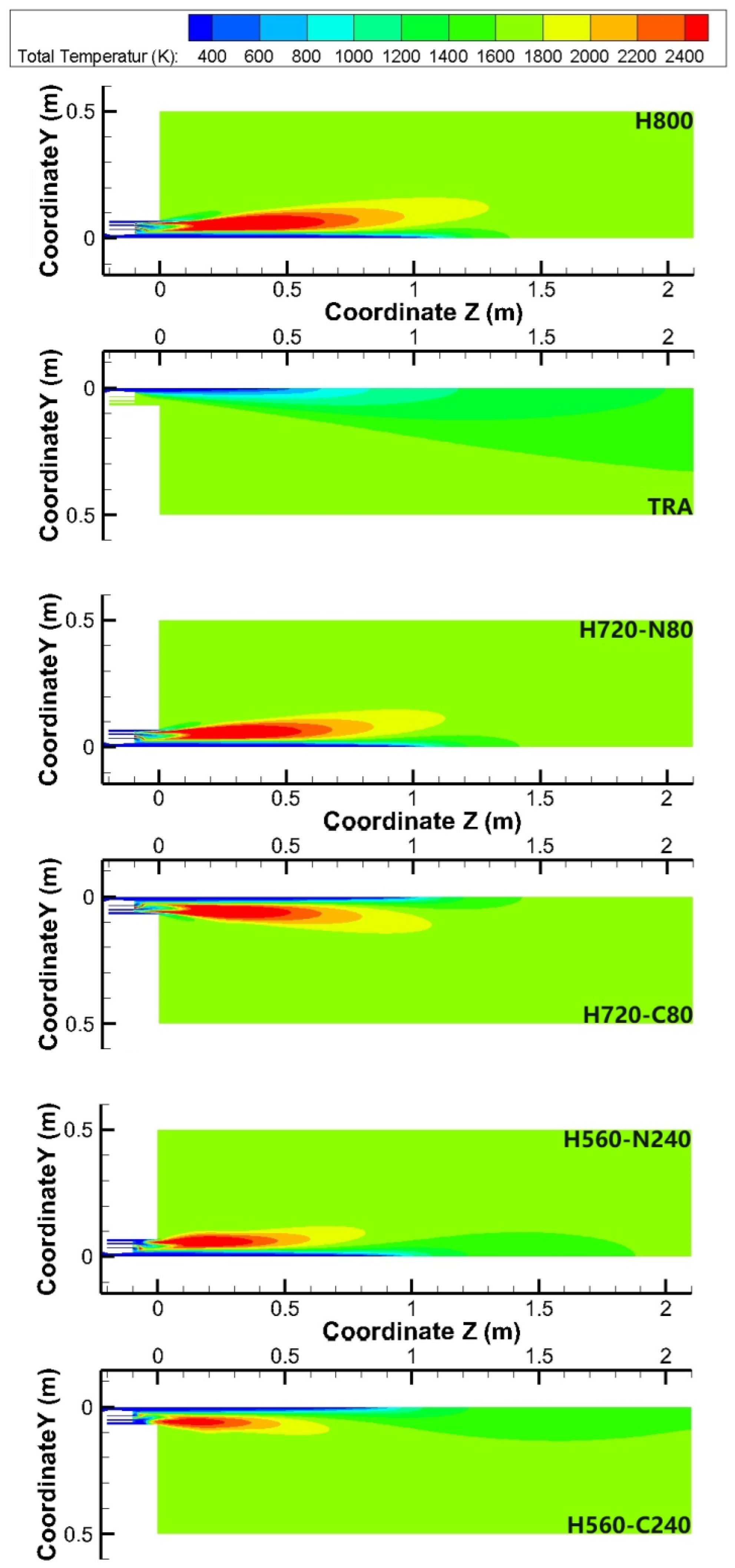
4.2. Total Temperature Distribution

Figure 5 depicts the total temperature profiles of the main oxygen jet using different fuel mixed injection methods at the centerline of the Laval nozzle. Based on the experimental test (□, ○, △ and ▽) and numerical simulation (solid and dotted lines), the average total temperature variation of the main oxygen jet is 3.9%, which further proves good agreement between the experimental data and the simulation results.
After the main oxygen jet passes through the Laval nozzle, a potential core for total temperature is generated, similarly to the axial velocity potential core. Based on the result, the potential core lengths of the total temperature and axial velocity are same. This means that the main oxygen jet will quickly mix with the ambient gas when it reaches the end of the potential core, leading to an obvious acceleration in total temperature and deceleration in the axial velocity of the main oxygen jet.
With a longer potential core length, the peripheral main oxygen jet can absorb more thermal energy from the high-temperature combustion flame, within the potential core. As a result, the total temperature of the peripheral main oxygen jet is increased. After the main oxygen jet reaches the end of the potential core, the internal and peripheral main oxygen jets swiftly mix with each other. During this process, the total temperature acceleration rate of the internal main oxygen jet is further increased by a higher total temperature of the peripheral main oxygen jet. Thus, the total temperature of the main oxygen jet more quickly arrives at the ambient temperature of 1700 K when its potential core is longer, as illustrated in Figure 5.
Based on the calorific value of the shrouding fuel jet, the per second calorific values using H800, H720-N80, H720-C80, H560-N240 and H560-C240 was 8644, 7779, 7779, 6050 and 6050 MJ/s, respectively. Meanwhile, the simulation result shows that the maximum total temperature of the shrouding combustion flame was 2970, 2922, 2857, 2753 and 2536 K, respectively. Hence, the maximum total temperature of the shrouding combustion flame is reduced with a higher shrouding mixed rate.
When the shrouding mixed rate is 10% and 30%, the total temperature variation between the H2-CO2 and H2-N2 shrouding mixed injection method was 65 and 217 K, respectively. This indicates that the maximum total temperature of the shrouding combustion flame formed by the H2-N2 shrouding mixed injection method is higher than that by the H2-CO 2 shrouding mixed injection method, at the same shrouding mixed rate.
As mentioned in Section 4.1, CO2 is one kind of oxidizing gas, and will take part in the combustion reaction of the shrouding H2 at a combustion temperature exceeding 1073 K, leading to the formation of unstable intermediate reaction products [23,24,25]. Thus, in order to research the effect of shrouding mixed rate and gas type on the flow field of the combustion flame, the total temperature of the coherent jet profiles using different fuel mixed injection methods is presented in Figure 6.
In this paper, both maximum Z and Y coordinates have been measured by the simulation model at the total temperature isoline of 2200 K to analyze the expansion rate of the shrouding combustion flame. The maximum axial and radial expansion rate of the shrouding combustion flame is defined as the ratio of maximum Z and Y coordinates of total temperature isoline of 2200 K, respectively, formed by the shrouding gas per second of the total heat value of the fuel shrouding jet. The maximum axial and radial expansion rate is addressed as the MAE-2200 and MRE-2200, respectively.
A higher MAE-2200 value indicates that there is a greater amount of high-temperature shrouding flame flowing alongside the main oxygen jet. This phenomenon suppresses the entrainment effect between the main oxygen jet and the ambient gas, while ensuring that the kinetic energy of the main oxygen jet remains unchanged.
The result shows that the MAE-2200 using H800, H720-N80, H720-C80, H560-N240 and H560-C240 was 9.06 × 10⁻⁵, 8.77 × 10⁻⁵, 8.23 × 10⁻⁵, 7.82 × 10⁻⁵ and 6.09 × 10⁻⁵ m/MJ, respectively. When the shrouding mixed rate is 10% and 30%, the MAE-2200 generated by the H2-N2 shrouding mixed injection method is 1.07 and 1.28 times higher than that by the H2-CO2 shrouding mixed injection method. Thus, the decrease in MAE-2200 is attributed to a higher shrouding fuel mixed rate, resulting in reduced protective effectiveness of the shrouding combustion flame in the axial direction.
Compared with the H2-CO2 shrouding mixed injection method, the H2-N2 shrouding mixed injection method can increase the MAE-2200 of the coherent jet, which suppresses the entrainment effect between the main oxygen jet and the ambient gas. Thus, N2 is a more suitable shrouding mixed gas type than CO2.
A higher MRE-2200 represents that more thermal energy from the shrouding combustion flame has been transferred into the ambient gas, resulting in a reduction in the heat utilization of the shrouding fuel gas and in the impaction ability of the main oxygen jet.
Based on the simulation result, the MRE-2200 using H800, H720-N80, H720-C80, H560-N240 and H560-C240 was 1.17 × 10⁻⁵, 1.22 × 10⁻⁵, 1.19 × 10⁻⁵, 1.43 × 10⁻⁵ and 1.37 × 10⁻⁵ m/MJ, respectively. Thus, the MRE-2200 is increased by a higher shrouding fuel mixed rate. This means that the ambient gas will absorb more thermal energy from the shrouding combustion flame, with a higher shrouding mixed rate.
When the shrouding mixed rate is 10% and 30%, the MRE-2200 generated by the H2-N2 shrouding mixed injection method is also 1.03 and 1.04 times higher than that by the H2-CO2 shrouding mixed injection method. Thus, compared with the H2-N2 shrouding mixed injection method, the H2-CO2 shrouding mixed injection method can suppress the radial heat transfer of the shrouding combustion flame.
Although the H2-CO2 shrouding mixed injection method reduces the radial heat transfer of the shrouding combustion flame, more thermal energy is consumed by the formation of the unstable intermediate reaction product, such as OH, CO and HCO, which reduces the protection effectiveness of the shrouding combustion flame for the main oxygen jet.

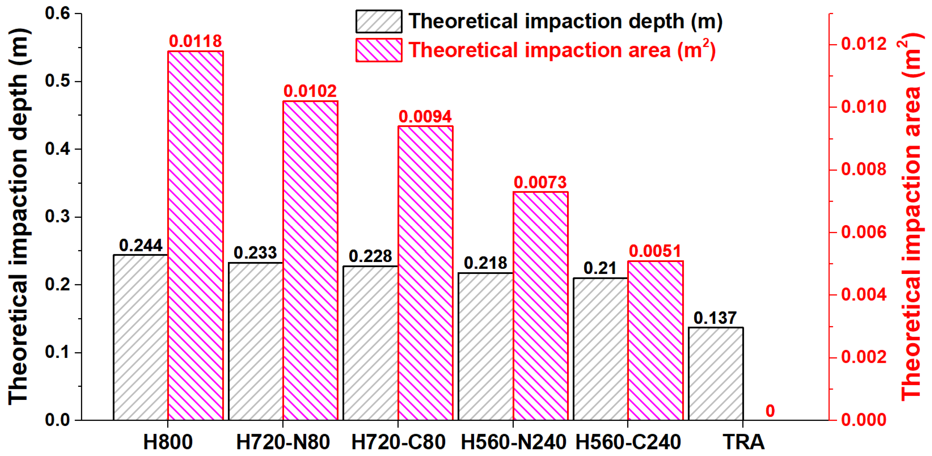
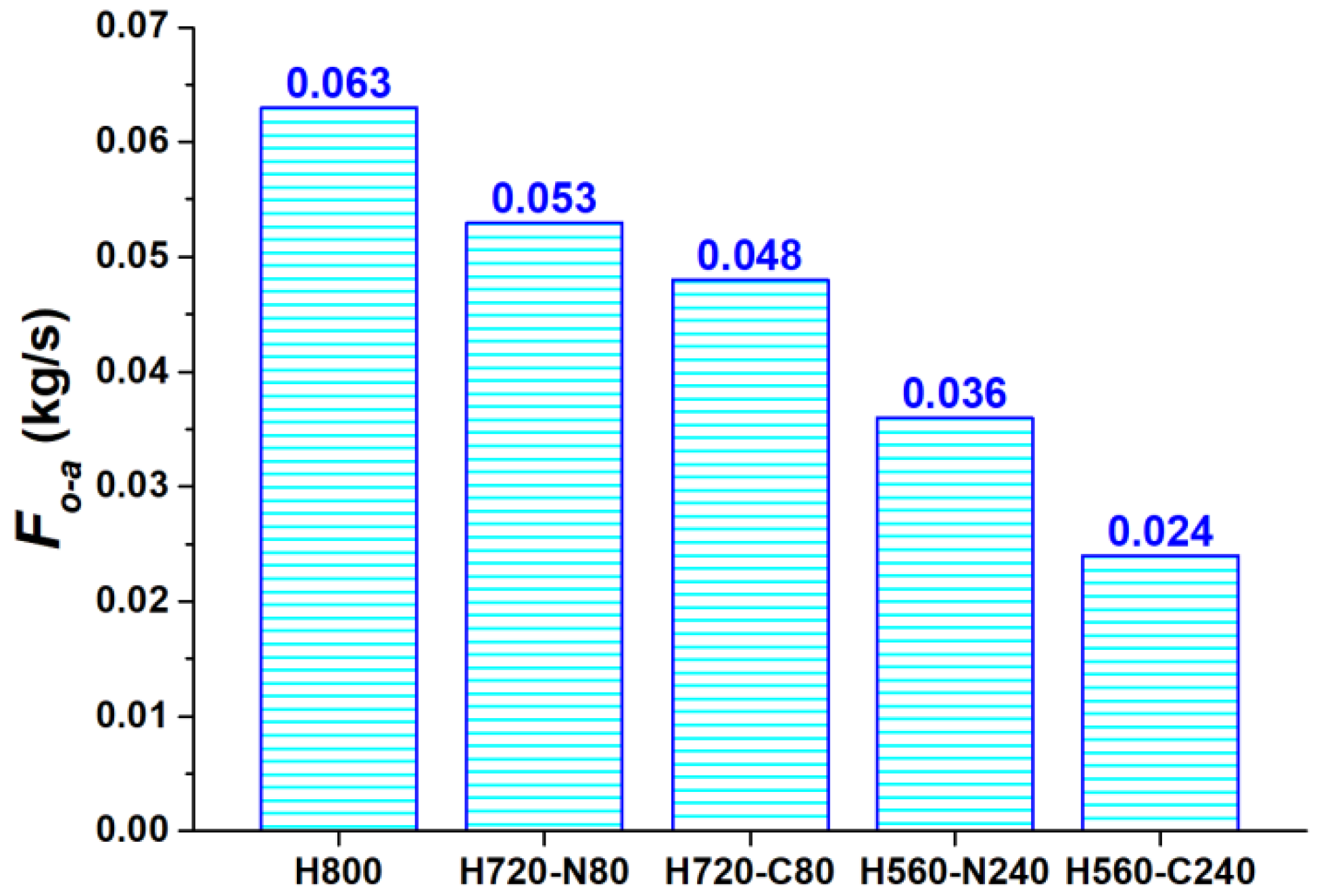
4.3. Impaction Cavity Parameters

The transfer of kinetic energy and oxygen mass between the molten bath and the coherent jet primarily occurs at the impaction cavity, due to the behavior of multiphase flow. This indicates that the shape of the impaction cavity significantly impacts the metallurgical technical indicators in the EAF steelmaking process.
There are two kinds of liquid flow, i.e., molten steel and liquid slag. Thus, the theoretical calculation model for these two-layer liquid phases has been adopted to calculate the impaction depth, with the following equations [26,27]:
H p = P d ρ s l a g g ,   H p   <   H slag ,
H p = H s l a g + H s t e e l = H s l a g + P d ρ s l a g g H s l a g ρ s t e e l g ,   H p     H slag ,
where Hp and Hsteel are the theoretical impaction depth and steel molten penetrate depth (m), respectively. Pd is the dynamic pressure of the coherent jet (Pa). The gravitational acceleration (g) and liquid slag thickness (Hslag) are 9.81 m2/s and 0.19 m, respectively. The liquid slag density (ρslag), and molten steel density (ρsteel) are set as 3000 and 7000 kg/m3, respectively.
Based on the coherent lance arrangement in a 120 t EAF structure, the lance height of the coherent is assumed to be 1.1 m, and its tilt angle is selected as 45°. This means that the distance between the coherent lance tip and the surface of the molten bath is about 1.56 m.
The maximum dynamic pressure of the coherent jet measured at a distance of 1.56 m from the coherent lance tip was derived from the simulation model. It is essential to acknowledge that this simulation model is the one constructed as detailed in Section 3, which is not a new simulation model, to calculate multiphase flow behavior. Subsequently, based on the maximum dynamic pressure of the coherent jet achieved in the simulation model, and the assumed data of molten steel and liquid slag, the theoretical impaction depth (Hp) can be calculated using Equation (5).
The theoretical impaction area is defined as the region, where the Hsteel formed by the coherent jet is bigger than 0.005 m. Hence, the edge of the theoretical impaction area is achieved by a coherent jet dynamic pressure of 5935 Pa, according to the Equation (5). Consequently, the area in which the dynamic pressure of the coherent jet exceeds 5935 Pa has been determined from the simulation model, referred to as the theoretical impaction area. Figure 7 represents the theoretical impaction depth and area generated by different fuel mixed injection methods.
The result shows that both theoretical impaction depth and area are reduced with a higher shrouding mixed rate. For the H2-N2 and H2-CO2 shrouding mixed injection methods, the average reduction rate of the theoretical impaction depth and theoretical impaction area is 7.2% and 36.7%, respectively, when the shrouding mixed rate is increased from 10% to 30%. Thus, the shrouding mixed injection method has a greater influence on the theoretical impaction area than that on the theoretical impaction depth.
When the shrouding mixed rate is 10% and 30%, the theoretical impaction depth generated by the H2-N2 shrouding mixed injection method is 1.02 and 1.04 times deeper than those by the H2-CO2 shrouding mixed injection method, respectively. The theoretical impaction area formed by the H2-N2 shrouding mixed injection method with shrouding mixed rates of 10% and 30% are 1.09 and 1.43 times larger than those by the H2-CO2 shrouding mixed injection method, respectively. Hence, compared with the H2-CO2 shrouding mixed injection method, the H2-N2 shrouding mixed injection method can increase the theoretical impaction depth and area, at the same shrouding mixed rate. This trend is more obvious with a higher shrouding mixed rate.
Comparing the coherent jet, the traditional supersonic jet cannot penetrate the liquid slag layer, leading to a theoretical impaction area of 0 m2, as shown in Figure 7. Based on the process of the oxygen mass transfer, the O element initially reacts with the Fe element in the liquid slag layer, resulting in the formation of (FeO). Subsequently, the (FeO) further undergoes displacement reactions with the elements [C], [P] and [Si] in the molten bath. Ultimately, the Fe element is reduced and enters the molten steel, and the [P] and [Si] elements are oxidized and transferred into the liquid slag. Simultaneously, the [C] element is oxidized into the CO or CO2 gas, which then enters the furnace gas.
For the coherent jet, a portion of the oxygen gas can penetrate the liquid slag, reacting directly with the elements [C], [P], and [Si] in the molten steel. Therefore, as more oxygen gas penetrates the liquid slag, the utilization rate of oxygen elements is increased, leading to lower oxygen consumption and reduced smelting time in the EAF steelmaking process.
In this research, the effective flow rate of oxygen gas through the theoretical impaction area is calculated by the simulation model, which is addressed as the Fo-a, as shown in Figure 8. A larger Fo-a indicates a higher oxygen utilization rate. The average Fo-a generated by the 10% and 30% shrouding mixed rate is 80.2% and 62.5% of the Fo-a generated by the H800, respectively. Thus, the Fo-a is decreased with a higher shrouding mixed rate.
Meanwhile, the Fo-a generated by the H2-N2 shrouding mixed injection method is 1.1 and 1.5 times larger than that by the H2-CO2 shrouding mixed injection method, when the shrouding mixed rate is 10% and 30%, respectively. This indicates that the H2-N2 shrouding mixed injection method can improve the oxygen utilization rate, comparing with the H2-CO2 shrouding mixed injection method. Therefore, the oxygen flow rate is obviously reduced with a higher shrouding mixing rate. Comparing with the inert N2, this trend is more evident when oxidizing CO2 has been used.

5. Conclusions

This research focuses on enhancing the utilization efficiency of hydrogen (H2), while minimizing its consumption. The conclusion of this research provides a fundamental understanding of coherent jets produced by the shrouding mixed injection method in high-temperature environments, specifically at 1700 K. The main conclusions of this research can be summarized as following:
  • Comparing with the traditional coherent jet, the total heat value of shrouding fuel gas is decreased using the shrouding mixed injection method. As a result, The axial velocity potential core length, Fo-a, theoretical impaction depth and area are all reduced with a higher shrouding mixed rate.
  • Oxidizing CO2 will take part in the combustion reaction of the shrouding H2, which reduces the combustion efficiency of shrouding H2, leading to decreased the protective effect of the shrouding combustion flame in the axial direction. Thus, N2 is a more suitable shrouding mixed gas type than CO2.
  • The Fo-a, theoretical impaction depth and area generated by the H720-N80 is 84.0, 95.5 and 86.4% of those generated by the H800, respectively. Comparing with the H800, the H720-N80 may still lead to comparable production indexes in the EAF steelmaking process, which is still required to verify by the industrial application test.
  • While the primary conclusions are derived from laboratory investigations that have not been confirmed through industrial application testing, they nonetheless provide insights into the behavior of the coherent jet produced by various shrouding mixing methods. These findings may offer valuable guidance for the utilization of H2 in the EAF steelmaking process.
  • In addition to achieving low-cost and large-scale production of green hydrogen, the storage and transportation of hydrogen energy within the steel enterprises present significant challenges. Consequently, addressing or mitigating hydrogen embrittlement is critical for the widespread adoption of hydrogen energy.

Author Contributions

Conceptualization, R.Z.; methodology, K.D.; software, F.L.; validation, none; formal analysis, G.W.; investigation, S.Y., F.L. and K.D.; resources, none; data curation, K.D.; writing—original draft preparation, S.Y. and F.L.; writing—review and editing, none; visualization, G.W.; supervision, R.Z.; project administration, R.Z.; funding acquisition, F.L. and G.W. All authors have read and agreed to the published version of the manuscript.

Funding

This research was funded by National Natural Science Foundation of China, grant number NSFC 52474343, NSFC 52322407, and NSFC 52293392.

Data Availability Statement

The original contributions presented in this study are included in the article. Further inquiries can be directed to the corresponding author.

Acknowledgments

The authors would like to express their thanks for the support by National Natural Science Foundation of China (NSFC 52474343, NSFC 52322407 and NSFC 52293392).

Conflicts of Interest

The authors declare no conflicts of interest.

References

  1. Mitas, B.; Schenk, J. Oxygen distribution at the hot spot in BOF steelmaking. Met. Mater. Trans. B 2024, 55, 1680–1689. [Google Scholar] [CrossRef]
  2. Yang, Z.; Yang, L.; Cheng, T.; Chen, F.; Zheng, F.; Wang, S.; Guo, Y. Fluid flow characteristic of EAF molten steel with different bottom-blowing gas flow rate distributions. ISIJ Int. 2020, 60, 1957–1967. [Google Scholar] [CrossRef]
  3. Gokce, F.; Adar, C.; Tosun, M.A.; Isik, Z.; Gurbuz, A.E. Nitrogen control in scrap-based EAF steelmaking. In Proceedings of the AISTech 2024, Columbus, OH, USA, 6–9 May 2024; pp. 393–400. [Google Scholar]
  4. Moreira, D.D.; de Souza, R.M.; Komati, K.S.; Sperandio, K.N.; Rodrigues, D.D.; de Oliveira, J.R. Study of the slag properties in steel dephosphorization in the EAF. In Proceedings of the AISTech 2024, Columbus, OH, USA, 6–9 May 2024. [Google Scholar]
  5. Ramirez-Argaez, M.A.; Conejo, A.N. CFD study on the effect of the oxygen lance inclination angle on the decarburization kinetics of liquid steel in the EAF. Metall. Res. Technol. 2021, 118, 516. [Google Scholar] [CrossRef]
  6. Alam, M.; Naser, J.; Brooks, G.; Fontana, A. Computational fluid dynamics modeling of supersonic coherent jets for electric arc furnace steelmaking process. Met. Mater. Trans. B 2010, 41, 1354–1367. [Google Scholar] [CrossRef]
  7. Chen, Y.; Luo, Q.; Ryan, S.; Busa, N.; Silaen, A.K.; Zhou, C.Q. Effect of coherent jet burner on scrap melting in electric arc furnace. Appl. Therm. Eng. 2022, 212, 118596. [Google Scholar] [CrossRef]
  8. Yamaguchi, M.; Yamamoto, Y.; Hagihara, Y. Functionalization of supersonic oxygen lance for EAF. In Proceedings of the AISTech 2021, Nashville, TN, USA, 29 June–1 July 2021; pp. 1592–1603. [Google Scholar]
  9. Tian, B.; Wei, G.; Zhu, R.; Li, X.; Zhang, H. Energy balance and deoxidation status of electric arc furnace tapping processes. Ironmak. Steelmak. 2022, 49, 699–706. [Google Scholar] [CrossRef]
  10. Wei, G.; Zhu, R.; Cheng, T.; Kai, D.; Yang, L.; Wu, X. Study on the impact characteristics of coherent supersonic jet and convention-al supersonic jet in EAF steelmaking process. Met. Mater. Trans. B 2018, 49, 361–374. [Google Scholar] [CrossRef]
  11. Jung, J.; Gabriel, T.; Partyka, A.; Pavliš, M. Application of jet-burner technology for a small-sized EAF. In Proceedings of the AISTech 2021, Nashville, TN, USA, 29 June–1 July 2021; pp. 307–316. [Google Scholar]
  12. Kourougianni, F.; Arsalis, A.; Olympios, A.V.; Yiasoumas, G.; Konstantinou, C.; Papanastasiou, P.; Georghiou, G.E. A comprehensive review of green hydrogen energy systems. Renew. Energy 2024, 231, 120911. [Google Scholar] [CrossRef]
  13. Bian, J.; Zhou, Z.; Yu, J.; Shi, X.; Huang, P.; Du, W. A comprehensive energy flow analysis method based on hydrogen energy to electric energy conversion. J. Phys. Conf. Ser. 2024, 2788, 012004. [Google Scholar] [CrossRef]
  14. Zaiter, I.; Ramadan, M.; Bouabid, A.; Mayyas, A.; El-Fadel, M.; Mezher, T. Enabling industrial decarbonization: Framework for hydrogen integration in the industrial energy systems. Renew. Sustain. Energy Rev. 2024, 203, 114782. [Google Scholar] [CrossRef]
  15. Zhu, Y.; Keoleian, G.A.; Cooper, D.R. The role of hydrogen in decarbonizing U.S. industry: A review. Renew. Sustain. Energy Rev. 2025, 214, 115392. [Google Scholar] [CrossRef]
  16. Feng, C.; Liu, F.; Zhu, R.; Kai, D.; Wei, G.; Tao, X. Computational investigation of coherent jet behavior generated by H2 shrouding flow. Metall. Mater. Trans. B 2024, 55, 600–611. [Google Scholar] [CrossRef]
  17. Mahoney, W.; Deneys, A.; Mathur, P.; Warty, S. The critical role of hydrogen in Linde’s coherent jet technology. In Proceedings of the AISTech 2023, Detroit, MI, USA, 8–11 May 2023; pp. 566–576. [Google Scholar] [CrossRef]
  18. Hu, S.; Zhu, R.; Dong, K.; Liu, R. Numerical simulation and industrial experimental research on the coherent jet with “CH4 + N2” mixed fuel gas. Metall. Mater. Trans. B 2018, 49, 2584–2598. [Google Scholar] [CrossRef]
  19. Adam, A.M.; Bahamon, D.; Kobaisi, M.A.; Vega, L.F. Molecular dynamics simulations of the interfacial tension and the solubil-ity of brine/H2/CO2 systems: Implications for underground hydrogen storage. Int. J. Hydrogen Energy 2024, 78, 1344–1354. [Google Scholar] [CrossRef]
  20. Vadlamudi, S.; Gugulothu, S.K.; Panda, J.K.; Chalapathi, K.S.; Mohanty, D. An ideal investigation on conventional CRDI engine for optimum paradigm analysis of performance and exhaust emissions by using oxygenated and hydrogen fuel: An experimental green dual fuel approach. Fuel 2024, 372, 132160. [Google Scholar] [CrossRef]
  21. Czylkowski, D.; Hrycak, B.; Miotk, R.; Dors, M.; Jasiński, M. Microwave plasma-assisted hydrogen production via conversion of CO2-CH4 mixture. Int. J. Hydrogen Energy 2024, 78, 421–432. [Google Scholar] [CrossRef]
  22. Sivells, J.C. Aerodynamic design of axisymmetric hypersonic wind-tunnel nozzles. J. Spacecr. Rocket. 1910, 7, 1292–1299. [Google Scholar] [CrossRef]
  23. Smith, G.P.; Golden, D.M.; Frenklach, M.; Moriarty, N.W.; Eiteneer, B.; Goldenberg, M.; Bowman, C.T.; Hanson, R.K.; Song, S.; Gardiner, W.C.; et al. GRI-Mesh 3.0. Available online: http://www.me.berkeley.edu/gri_mech/ (accessed on 5 March 2025).
  24. Mashruk, S.; Zhu, X.; Roberts, W.L.; Guiberti, T.F.; Valera-Medina, A. Chemiluminescent footprint of premixed ammonia-methane-air swirling flames. Proc. Combust. Inst. 2023, 39, 1415–1423. [Google Scholar] [CrossRef]
  25. Liu, Y.; Gong, Y.; Guo, Q.; Tian, X.; Yu, G. Numerical study on OH* chemiluminescence in CH4/NH3 diffusion flame based on chemical kinetic mechanism. Int. J. Hydrogen Energy 2025, 105, 1230–1241. [Google Scholar] [CrossRef]
  26. Qian, F.; Mutharasan, R.; Farouk, B. Studies of interface deformations in single- and multi-layered liquid baths due to an im-pinging gas jet. Met. Mater. Trans. B 1996, 27, 911–920. [Google Scholar] [CrossRef]
  27. Li, M.; Li, Q.; Kuang, S.; Zou, Z. Determination of cavity dimensions induced by impingement of gas jets onto a liquid bath. Met. Mater. Trans. B 2016, 47, 116–126. [Google Scholar] [CrossRef]
Figure 1. Cross view (a) and front view (b) of the coherent lance.
Metals 15 00291 g001
Figure 2. The (a) physical diagram, (b) front view and (c) cross view of the high temperature combustion furnace. (Unit: mm).
Metals 15 00291 g002
Figure 3. (a) Geometric construction of the numerical model. (b) Mesh profile of the numerical model with boundary conditions.
Metals 15 00291 g003
Figure 4. The axial velocity profiles of the main oxygen jet using different fuel mixed injection methods at the centerline of the Laval nozzle: (a) 10% shrouding fuel mixed method. (b) 30% shrouding fuel mixed method.
Metals 15 00291 g004
Figure 5. The total temperature of main oxygen profiles using different fuel mixed injection methods at centerline of the Laval nozzle: (a) 10% shrouding fuel mixed method. (b) 30% shrouding fuel mixed method.
Metals 15 00291 g005
Figure 6. The total temperature of coherent jet profiles using different fuel mixed injection methods.
Metals 15 00291 g006
Figure 7. The theoretical impaction depth and area generated by different fuel mixed injection methods.
Metals 15 00291 g007
Figure 8. The effective oxygen flow rate through the theoretical impaction area using different fuel mixed injection methods.
Metals 15 00291 g008
Table 1. Operational conditions.
LabelType of Detail ConditionsValues
Main Laval nozzleFlow rate (Nm3/h)2500
Mach number2.20
Oxygen temperature (K)300
Fuel shrouding nozzleH2 flow rate (Nm3/h)800/720/560
N2 flow rate (Nm3/h)0/80/240
CO2 flow rate (Nm3/h)0/80/240
Gas flow temperature (K)300
Oxygen shrouding nozzleFlow rate (Nm3/h)400/360/280
Gas flow temperature (K)300
Table 2. The average velocity of the coherent jet generated by various mixed injection methods.
LabelH800TRAH720-C80H720-N80H560-C240H560-N240
1.00 m216.8 m/s134.1 m/s204.4 m/s208.7 m/s184.8 m/s194.6 m/s
1.25 m173.0 m/s110.3 m/s163.2 m/s166.4 m/s148.1 m/s155.2 m/s
1.50 m140.1 m/s93.5 m/s132.7 m/s135.0 m/s121.7 m/s126.7 m/s
1.75 m114.9 m/s80.6 m/s109.6 m/s111.2 m/s101.8 m/s105.2 m/s
Disclaimer/Publisher’s Note: The statements, opinions and data contained in all publications are solely those of the individual author(s) and contributor(s) and not of MDPI and/or the editor(s). MDPI and/or the editor(s) disclaim responsibility for any injury to people or property resulting from any ideas, methods, instructions or products referred to in the content.

