Article

Auxetic Meta-Biomaterials: Computer Simulation and Experimental Results

Institute of Machinery, Materials, and Transport, Peter the Great St. Petersburg Polytechnic University (SPbPU), Polytechnicheskaya, 29, 195251 Saint Petersburg, Russia
*
Author to whom correspondence should be addressed.
Metals 2025, 15(3), 241; https://doi.org/10.3390/met15030241
Submission received: 24 January 2025 / Revised: 20 February 2025 / Accepted: 23 February 2025 / Published: 25 February 2025
(This article belongs to the Section Additive Manufacturing)

Abstract

:
One of the issues the modern hip implants face is that one side of the implant may detach due to stretching during its use. This leads to implant transverse compression and separation from the bone. This issue can be solved by using complex implants having one of the sides made of auxetic meta-biomaterials with negative Poisson’s ratio. On the contrary, the cross-section of such materials being stretched will increase, which results in bone growth stimulation and minimum possibility of implant detachment. The aim of this paper is to design and fabricate titanium alloy auxetic meta-biomaterials based on 3D unit cells with three types of topologies. The works involved computer simulation to determine the expected properties of the samples. The samples were fabricated by the selective laser melting method and their properties were determined. Auxetic meta-biomaterials with Poisson’s ratio values of −0.09 and −0.003 and elastic modulus values typical for a human trabecular bone were fabricated in the course of the works.

1. Introduction

Meta-biomaterials are intentionally designed materials featuring a specific architecture (geometry) and rare and non-standard combinations of mechanical, physical, and biological properties. Similar to other types of metamaterials, the properties of meta-biomaterials primarily depend on their microarchitecture, which involves both the meta-biomaterial geometry at several scales (macro-, micro-, and nano-scale) and distribution of different material types in the meta-biomaterial structure [1,2,3]. The active development of additive technologies allowing for the fabrication of products with complex geometry on a small scale had a positive effect on the development of this type of meta-biomaterials [4,5,6].
Auxetic meta-biomaterials are one of the currently developing types of meta-biomaterials. This type is based on auxetic meta-materials, i.e., the materials with negative Poisson’s ratio. Such materials may compress transversely when compressed longitudinally, and conversely, expand transversely when stretched longitudinally [7,8]. These properties make the auxetic meta-biomaterials a perfect fit for some types of implants (hip implants) and can solve certain specific problems or tasks [5,9].
A specific feature of classical hip implants is that they are made of metallic biomaterials (for example, titanium alloys) with a positive Poisson’s ratio [10]. Hip implants are subject to bending during mechanical loading, which makes one side of the implant compress, while the other side becomes stretched [1]. Accordingly, one side of the implant will always be pressed against the bone, while the other, on the contrary, will be drawn aside. The latter side is more susceptible to interface surface damage. In addition, the implant drawn aside allows wear particles to penetrate into the space between the implant and the bone, causing the patient’s immune system to react to the foreign body, which results in inflammatory bone loss, detachment, and failure of the implant [4,11,12]. Consequently, the implant-to-bone contact must be maximized so that wear particles do not penetrate into the space, and additional compression of the implant by the bone improves its fixation by mechanically stimulating bone ingrowth [12]. The materials with negative Poisson’s ratio (auxetics) can help to solve the said problem by using them in designing and fabricating implants with a complex structure. The implant side subjected to continuous stretching will be made of a meta-biomaterial with negative Poisson’s ratio (auxetic). Due to this, the side will exert additional pressure on the bone–implant interface when used cyclically, mechanically stimulating bone growth and blocking the possibility of bone tissue detachment and inflammation [11,12,13].
Therefore, it is necessary to develop auxetic meta-biomaterials for designing and fabricating implants with a complex structure that can help to solve the said problem. In fact, such implants should be customizable, manufactured using additive technologies, taking into account the anatomical requirements of the patient, which is another step towards personalized medicine [14]. At present, the number of research teams and papers on auxetic meta-biomaterials development is extremely limited [1,12,13]. Research on this topic needs to be further expanded, including expansion of the geometries used. The current situation is that the standard re-entry geometries based on a flat unit cell of the “honeycomb” type are usually used as the geometry for creating metamaterials and auxetic meta-biomaterials [1,4,15,16]. Only on some occasions has this geometry served as the basis to develop 3D unit cell topologies for fabricating auxetic metamaterials [9,17,18]. It should be noted that this approach is the most optimum, since a 3D unit cell makes it easier to simulate and design both a metamaterial and a prospective product. This approach could potentially simplify the design of personalized implants with a complex structure.
Meanwhile, the discipline on using nature-like geometries for fabricating materials with special or non-standard properties is actively developing [19,20,21,22]. For example, the patent [23] presented the geometry of a metamaterial with negative Poisson’s ratio. This geometry was designed on the basis of a six-beam or glass sponge skeleton (Lat. Hexactinellida) and fabricated from Ti6Al4V alloy. According to the authors, the produced metamaterial can be used in protective energy absorption systems. Such geometry can also be applied to design auxetic meta-biomaterials. The geometry is based on struts, which facilitates the design of metamaterial samples based on this geometry.
To sum it up, this paper is aimed at designing and fabricating titanium auxetic meta-biomaterials based on 3D unit cells with geometries of two types: re-entry honeycomb and nature-like geometry on the basis of a six-beam or glass sponge skeleton (Lat. Hexactinellida). This approach allows us to both explore properties of single-unit cells based on “classical” re-entry geometry and to expand the possible list of auxetic geometries using a nature-like approach to design. It is also worth noting the experience in developing similar 3D cells based on inverse geometries [17]. Based on the results of the study, the properties of meta-biomaterials based on the selected unit cell topologies will be assessed and the topologies with the greatest potential for further research will be identified.
Ti Grade 2 will be used as a base material for meta-biomaterials due to its widespread use as a biomaterial, lower elastic modulus, and greater plasticity compared to Ti6Al4V alloy [24,25]. The choice of titanium is also based on the prospects for its use in products, including implants made from several materials (multi-material implants), when the supporting part of the implant is made from Ti6Al4V alloy, and the part in contact with the bone is made from another, more flexible material [26,27]. This paper describes meta-biomaterials characterization through numerical computer simulations with further experimental data-based validation. The “simulation-experiment” link application allows for further use of the described approach in effective design and fabrication of metamaterials, including meta-biomaterials with predetermined properties, which is one of the steps for transition to personalized medicine.

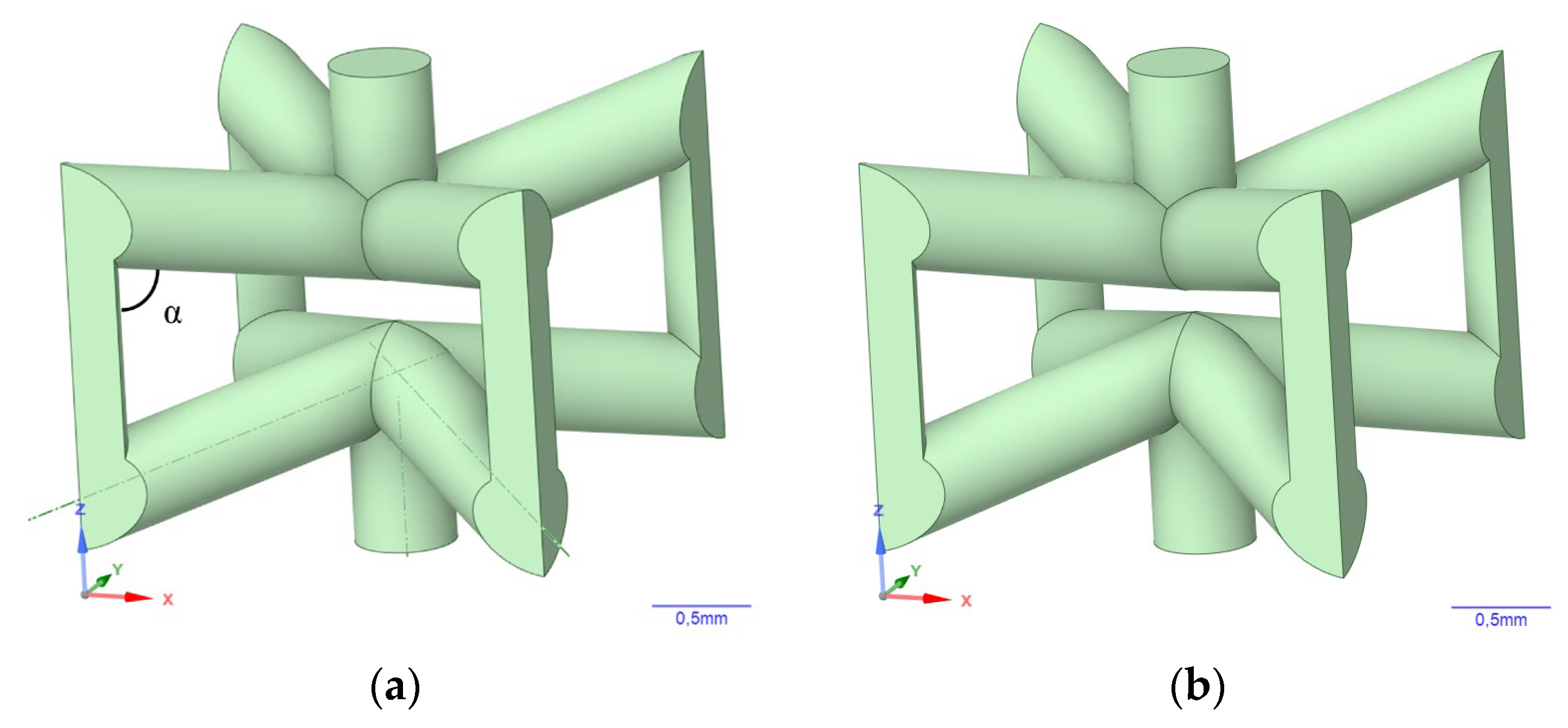
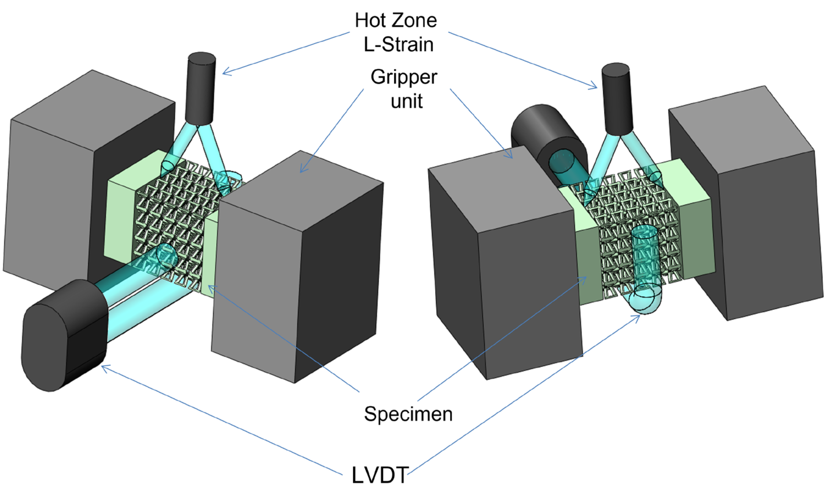
2. Materials and Methods

The initial models of auxetic meta-biomaterial unit cells and meta-biomaterial samples were simulated using ANSYS 2019 R2 SpaceClaim (ANSYS 2019 R2, Ansys Inc., Canonsburg, PA, USA) software package. The dimensions of meta-biomaterial unit cells were 2.5 mm × 2.5 mm × 2.5 mm. The meta-biomaterial samples consist of 5 × 5 × 5 unit cells with total dimensions of 12.5 mm × 12.5 mm × 12.5 mm. Three unit cell topologies were simulated: Strut_Auxetic_P, abbreviated St.A_P (based on the development presented in the patent [23]), Strut_Auxetic_1 (St.A_1), and Strut_Auxetic_2 (St.A_2) (the models of TiNi alloy-based metamaterials were previously presented in the paper [28]). The difference between these topologies is in the internal angle α between the center-oriented struts and the edges of the unit cell. For Strut_Auxetic_1 topology this angle is 78°, and for Strut_Auxetic_2 topology—76°. The models of unit cells for each topology and a sample with St.A_P topology are shown in Figure 1 and Figure 2.
ANSYS 2019 R2 SpaceClaim software package was used to determine the mechanical characteristics of the simulated meta-biomaterials (Young’s modulus (E), shear modulus (G), and Poisson’s ratio), by conducting the simulation of compression experiment with static load in elastic region using FEM. The following boundary conditions were used to determine the elastic characteristics: for Young’s modulus (E), normal displacement without friction was applied on the lower face, and small displacement corresponding to 0.01% strain was applied on the upper face of meta-biomaterial samples. For shear modulus (G): normal displacement without friction was applied on the lower and upper faces, and small displacement corresponding to 0.01% deformation was applied on the lateral surface of meta-biomaterial samples.
SOLID187 elements were used for FEM. It is a high-order 3D, 10-node element. The element has a quadratic displacement behavior and is well suited to modeling irregular meshes. For the St.A_P topology, the number of elements was 50,674, the number of nodes was 83,385. For St.A_1 topology there were 11,191 elements and 18,828 nodes, and for St.A_2 topology, there were 11,719 elements and 19,643 nodes.
The auxetic meta-biomaterials were fabricated from Ti Grade 2; the chemical composition is given in Table 1. To determine the alloy initial properties used during simulation, the samples given below were fabricated from the alloy spherical powder by the SLM technique: cylindrical samples with the following parameters: d = 3 mm, h = 13 mm for compression to failure tests, d = 10 mm, h = 90 mm—to determine elastic modulus, d = 6 mm (working section) h = 63 mm—for tensile tests, d = 5.7 mm (working section) h = 53 mm—for torsion tests.
The samples for determining Ti Grade 2 properties and the auxetic meta-biomaterial samples were fabricated using the 3DLAM Mini SLM system (by 3DLAM Company, Saint-Petersburg, Russia). The system is equipped with a IPG Photonics fiber laser with a cylindrical-shaped print zone, 90 mm in diameter and 100 mm high. The samples were fabricated in inert gas atmosphere (argon). The fabrication process parameters: laser power—150 W, scanning rate—1200 mm/s, distance between laser passes—0.12 mm, layer thickness—0.03 mm, spot diameter—0.08 mm. The orientation of the alloy samples on the build plate, with the building direction indicated, is shown in Figure 3. After fabrication, the alloy and meta-biomaterial samples were thermally treated at 750 °C for 120 min in vacuum, with furnace cooling.
The fabricated meta-biomaterial samples were visually examined using TESCAN Mira 3 LMU (TESCAN, Brno, Czech Republic) scanning electron microscope in secondary electron (SE) modes. The porosity of meta-biomaterial samples was calculated by Formula (1) [29,30]:
P = (1 − p*/ps),
where p* is meta-biomaterial sample density, ps is density of the material from which the meta-biomaterial sample is fabricated.
The initial alloy samples and meta-biomaterial samples were tested for compression, including compression to failure, and for tension using a Zwick/Roell Z100 single-axis floor-mounted testing machine. A Gleeble 3800 (Dynamic Systems Inc., Austin, TX, USA) testing machine was used to carry out torsion tests and to determine axial strain and transverse strain of compressed meta-biomaterial samples, while Hot Zone L-Strain and LVDT C-Gauge were applied for Poisson’s ratio calculation. The schematic location of the sample and sensors is shown in Figure 4. The obtained data served as the basis to calculate the Poisson’s ratio for meta-biomaterial samples by formula (2) [31]:
ν = −εt
where εt is relative transverse strain of the sample calculated as δb/b, b is sample width, ε is relative axial strain of the sample calculated as δ|/|, | is sample length [32].

3. Results

3.1. Alloy Initial Properties

The properties given in Table 2 were obtained when testing dense Ti Grade 2 alloy samples fabricated by the SLM technique.
Figure 5 shows a stress–strain curve of compressed alloy that is loaded to the ANSYS 2019 R2 SpaceClaim software package to simulate the properties of meta-biomaterials.

3.2. Simulation Results

The properties of meta-biomaterials, i.e., elastic modulus (E), shear modulus (G), and Poisson’s ratio (ν), were obtained by the simulation for three topologies of unit cells with 80%, 70%, and 60% porosities. The properties are given in Table 3. The thickness (T) of struts of meta-biomaterial sample models is additionally indicated.

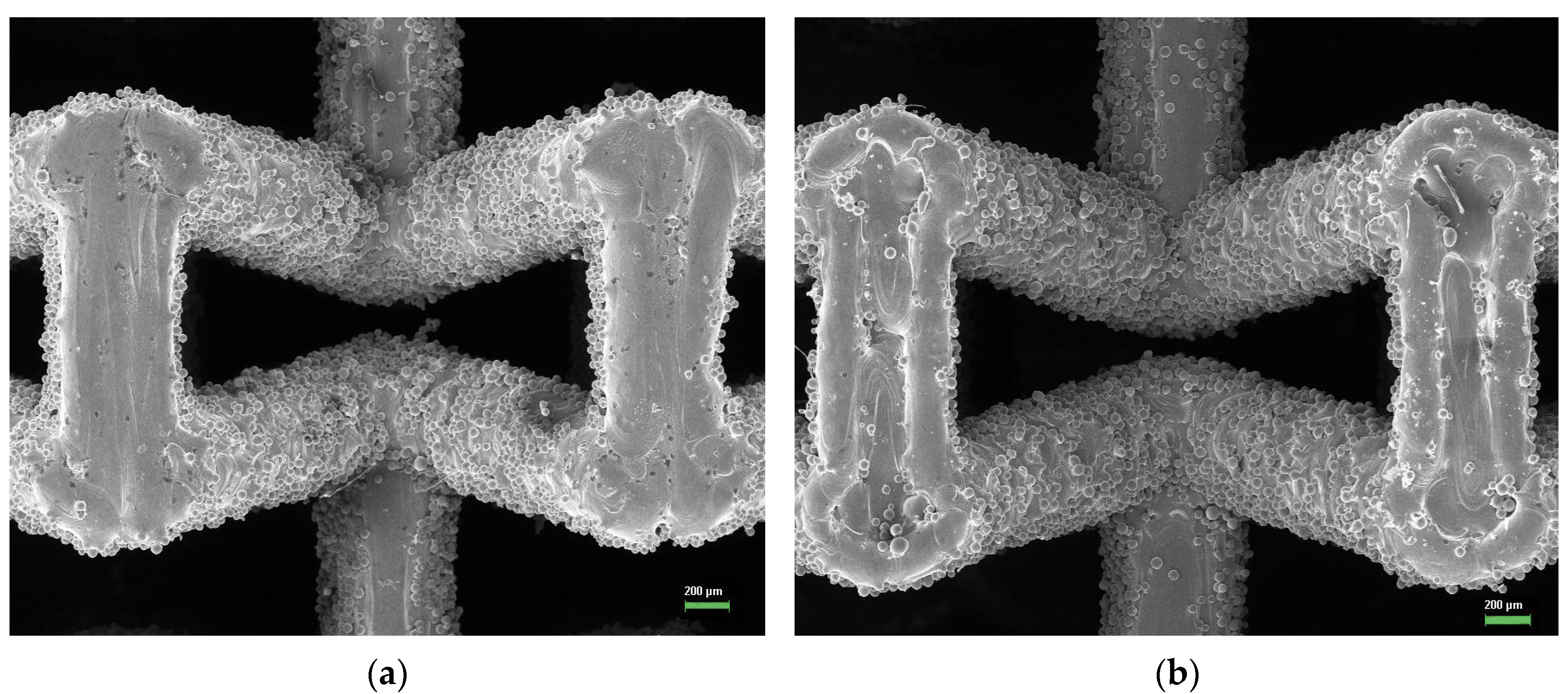
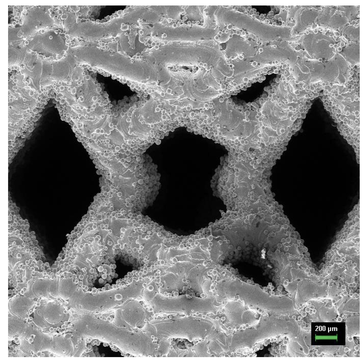
3.3. Fabricated Meta-Biomaterial Samples

Meta-biomaterial samples were manufactured based on models with 80% porosity. The choice of 80% porosity is justified by the presence of the lowest values of the elastic modulus and the highest negative values of the Poisson’s ratio determined during simulation (Table 3). Same as original models, the meta-biomaterial samples consist of 5 × 5 × 5 unit cells with total dimensions of 12.5 mm × 12.5 mm × 12.5 mm, with the addition of dense bases measuring 12.5 mm × 12.5 mm × 5 mm at the top and bottom. Seven samples of each topology were manufactured. Figure 6 shows a group of meta-biomaterial samples with St.A_P and St.A_1 topologies on a substrate after fabrication by the SLM technique.
Figure 7 and Figure 8 show SEM images of unit cells of meta-biomaterial samples with St.A_1, St.A_2, and St.A_P topologies, respectively, in the front projection (in the plane perpendicular to the sample building direction). A great number of powder particles are stuck to the struts of unit cells of all samples. The average thickness of unit cell struts determined in the said plane are as follows: for the sample with St.A_1 topology—597.60 ± 12.24 µm, for the sample with St.A_2 topology—606.35 ± 17.46 µm, for the sample with St.A_P topology—427.60 ± 25.28 µm. For comparison, the initial strut thicknesses of the models with a porosity of 80% are presented in Table 3. Porosity of the fabricated meta-biomaterial samples are as follows: for the sample with St.A_1 topology—76.35 ± 0.11%, for the sample with St.A_2 topology—74.52 ± 0.10%, for the sample with St.A_P topology—66.12 ± 0.19%.

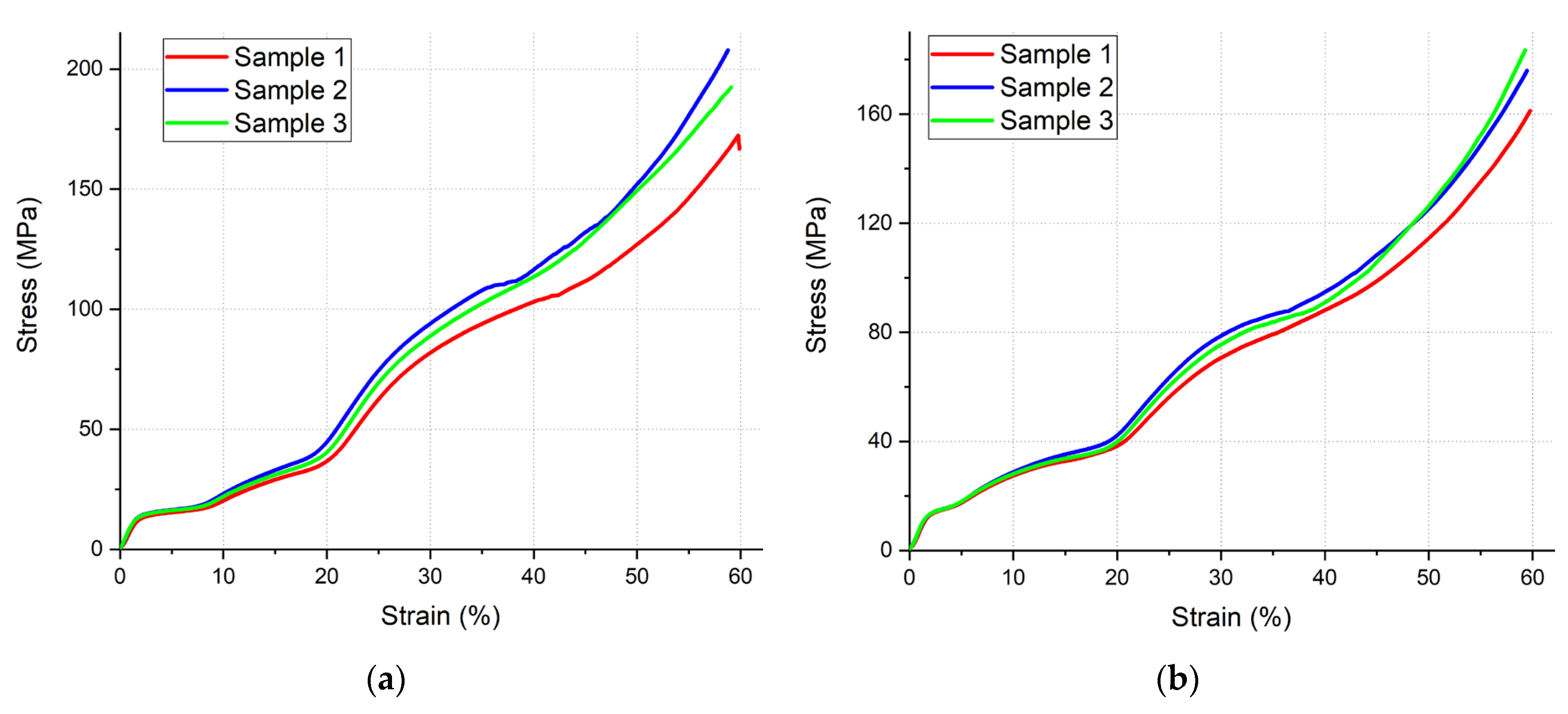
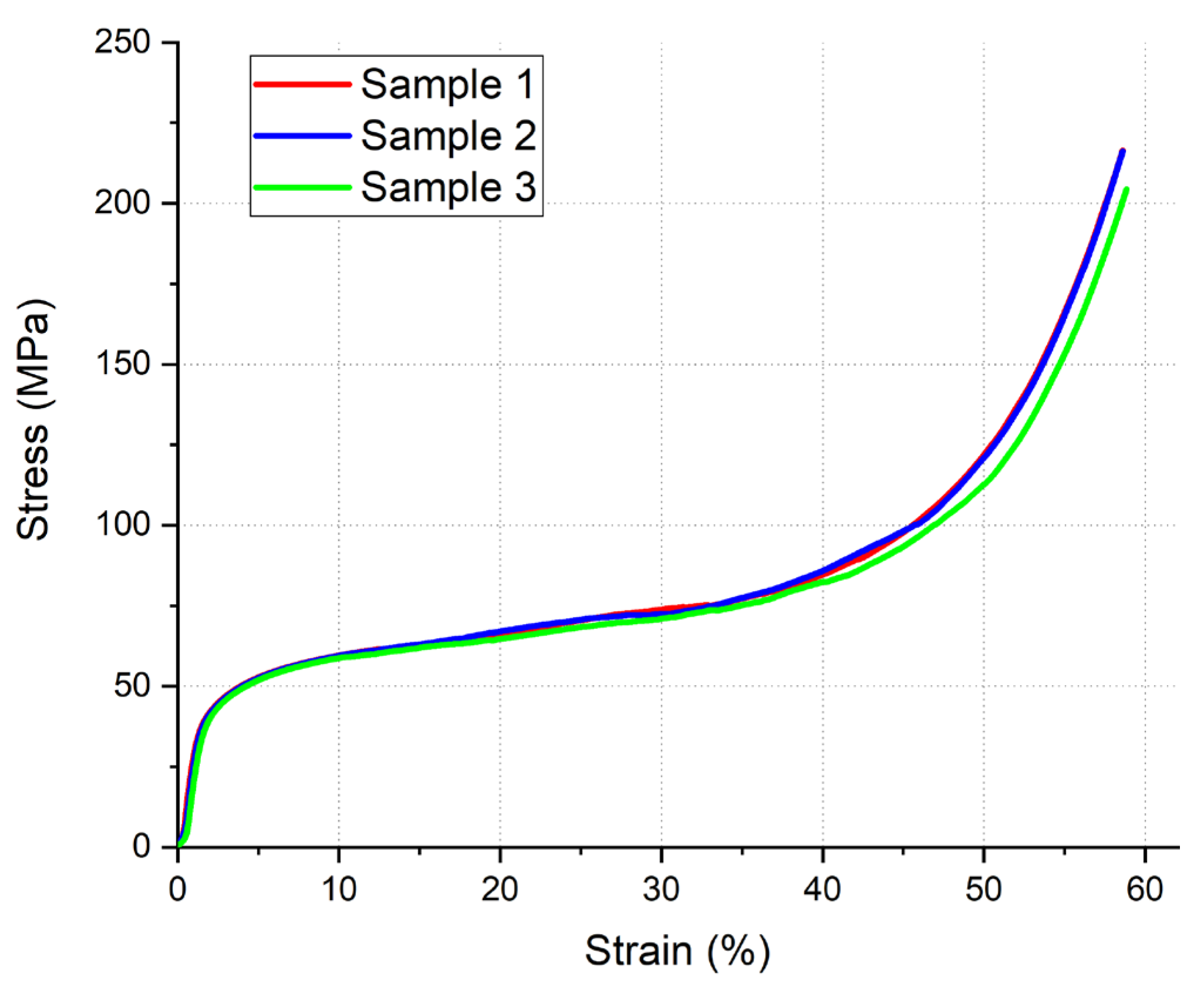
3.4. Compression Test

Figure 9 and Figure 10 show the samples of meta-biomaterials with St.A_1, St.A_2, and St.A_P topologies before and after compression tests. Three samples of each topology were tested. Compression was limited to a strain level of 8 mm, as larger strain is not practical or informative. It can be noted that failure of the samples does not occur. The unit cells are gradually compressed, actually until the samples are compacted.
Figure 11 and Figure 12 show the stress–strain curves of meta-biomaterial samples plotted on the basis of compression test results. As can be seen from the figures, gradual plastic deformation and compaction of the samples occurs during the compression. Brittle destruction of individual cells or groups of cells, accompanied by a sharp drop in mechanical stress, does not occur. For topologies St.A_1 and St.A_2, a gradual wave-like increase in stress is observed. For topology St.A_P, a slow increase in mechanical stress values is observed, with a sharp increase at deformations greater than 45%. In general, the samples are characterized by high plasticity. The basic values of conditional elastic modulus and conditional yield strength obtained for all samples are summarized in Table 4.

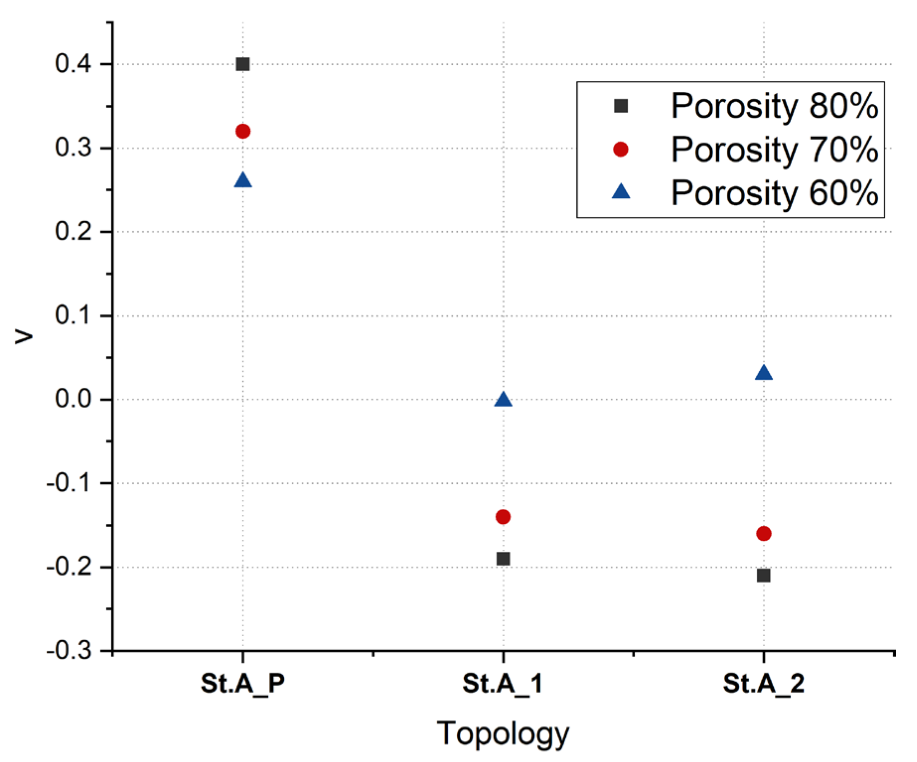
3.5. Poisson’s Ratio

Figure 13 and Figure 14 shows the results of tests conducted to determine Poisson’s ratio values for meta-biomaterial samples with St.A_1, St.A_2, and St.A_P topologies, respectively. The transverse size of meta-biomaterial samples with St.A_1 and St.A_2 topologies reduces when compressed longitudinally. This indicates that these samples have a negative Poisson’s ratio. The transverse size of samples with St.A_P topology increases when compressed longitudinally. This indicates that the samples with this topology have a positive Poisson’s ratio. Then, the values of Poisson’s ratio were calculated for all samples by Equation (2): υ = −0.09 for St.A_1 topology, υ = −0.003 for St.A_2 topology, υ = 0.63 for St.A_P topology. Thus, meta-biomaterials with St.A_1 and St.A_2 topologies have negative Poisson’s ratio; consequently, they can be characterized as auxetic meta-biomaterials.

4. Discussion

Figure 15 shows the graphs of meta-biomaterial samples elastic modulus (a) and shear modulus (b) dependence on their porosity as obtained from the simulation results. The values of elastic modulus and shear modulus increase as porosity of the metamaterials decreases. As for the St.A_P topology, a reduced porosity resulted in an almost 7-fold increase in elastic modulus, from 2.93 to 18.38 GPa. In a similar manner, shear modulus values for this topology increase rather sharply while the metamaterial porosity decreases. The lowest elastic modulus value obtained for the St.A_2 topology, at 80% porosity, was 0.77 GPa.
It can be noted that the elastic modulus values for simulated meta-biomaterials with St.A_P topology at 80% porosity, and with St.A_1 and St.A_2 topologies at 80% and 70% porosities are within the range typical for a human trabecular bone—from 0.1 to 5 GPa [33]. For the St.A_P topology at 60% porosity, the elastic modulus value corresponds to the upper limit of values typical for the elastic modulus of a human cortical bone—from 12 to 18 GPa [34,35,36] (some papers indicate the interval of 11–21 GPa or 7–30 GPa [37,38,39]).
Figure 16 shows the graph of meta-biomaterial samples Poisson’s ratio dependence on the porosity level as obtained from the simulation results. The meta-biomaterial with St.A_P topology has no negative Poisson’s ratio. In this regard, a reduced porosity decreases the Poisson’s ratio value for this topology.
On the contrary, meta-biomaterials with St.A_1 and St.A_2 topologies have negative Poisson’s ratio, and, consequently, they can be characterized as auxetic meta-biomaterials. The decrease in porosity from 80% down to 70% slightly reduced the negative values, while the decrease in porosity down to 60% resulted in a sharp jump to near zero values of Poisson’s ratio. The highest negative value of Poisson’s ratio equal to −0.21 at 80% porosity was reached for the meta-biomaterial with St.A_2 topology.
Table 5 presents the analyzed and compared properties of meta-biomaterial samples obtained from the results of simulation and experiments. The table contains the values of elastic modulus, porosity, strut thickness, and Poisson’s ratio as well as the deviations between the values obtained by simulation and experiments.
It was found that the obtained value of elastic modulus for all topologies exceeded the one assumed in the simulation. This is primarily due to reduced porosity of the fabricated meta-biomaterial samples, a greater thickness of the unit cell struts that may be also caused by the powder particles stuck to the struts. The side view (the plane being parallel to the building direction; refer to Figure 17) shows an even greater increase in strut thickness with substantial powder adhesion to the struts. The average strut thicknesses within this plane are as follows: for the sample with St.A_1 topology—849.36 ± 24.05 µm, for the sample with St.A_2 topology—926.23 ± 22.81 µm, for the sample with St.A_P topology—713.66 ± 73.06 µm. At the same time, the average struts thickness determined in the in the front projection are as follows: for the sample with St.A_1 topology—597.60 ± 12.24 µm, for the sample with St.A_2 topology—606.35 ± 17.46 µm, for the sample with St.A_P topology—427.6 ± 25.28 µm, and the initial strut thicknesses of the metamaterial sample models were 519 µm for St.A_1 topology, 516 µm for St.A_2 topology, and 335 µm for St.A_P topology (Table 3). Therefore, it can be expected that the struts of meta-biomaterial sample unit cells do not have a round cross section, as was assumed during the simulation, but they are somewhat elongated, drop-shaped. These specific features associated with orientation of the samples during the fabrication, as well as the features of the SLM technique itself; for example, the possibility of multiple remelting of several lower layers when scanning the upper layer, cannot be taken into account in the software package and simulation technique used. This leads to the presence of certain deviations between the simulated and experimental results.
At the same time, it should be noted that the experimentally obtained porosity values for meta-biomaterial samples with St.A_1 and St.A_2 topologies are quite close to the simulated ones: the deviation for St.A_1 topology was 3.65% (76.35% porosity), for St.A_2 topology—5.48% (74.52% porosity). The lowest deviation (19.24%) of elastic modulus was obtained for the sample with St.A_2 topology, with an elastic modulus of 0.92 GPa. For St.A_1 topology, the deviation according to the elasticity module was 23.59%, with an experimentally obtained value of 0.98 GPa. The sample with St.A_P topology had the highest deviation of elastic modulus—58.66%. The experimental value of the elastic modulus was 4.65 GPa. This is primarily due to a reduced level of porosity, which amounted to 66.12% (deviation 13.88%). It should be noted that despite the obtained lower porosity the sample with St.A_P topology had a lower elastic modulus value than the value simulated at 70% porosity. The important point is that all experimental samples of meta-biomaterials with the topologies under study show the elastic modulus values corresponding to the range of values typical for a human trabecular bone—from 0.1 to 5 GPa [33].
Quite significant deviations from the simulated values are observed for Poisson’s ratio of the samples. The highest deviation of over 90% was observed for the sample with St.A_2 topology. For the St.A_1 and St.A_P topologies, the deviations were slightly more than 50% (52.63% and 57.50%, respectively). The quite significant deviations found when determining the Poisson’s ratio values for the samples may result from the reduced porosity of the samples as compared to the simulated porosity, and, possibly, from the low accuracy of the obtained experimental results, due to the extremely small values of the sample’s strain during the tests. This could lead to the accumulation of errors, which, given the need to carry out final calculations, could lead to certain deviations.
At the same time, the Poisson’s ratio values determined for the samples can be called indicative. As assumed in the simulations, the meta-biomaterial samples with St.A_1 and St.A_2 topologies have negative Poisson’s ratio, with values of −0.09 and −0.003, respectively. Consequently, they can be characterized as auxetic meta-biomaterials. In addition, the simulation results for the St.A_P topology have been confirmed. The Poisson’s ratio value for this topology turned out to be positive both in the simulation (0.40) and according to the experimental results (0.63). Consequently, the sample of meta-biomaterial with St.A_P topology is not an auxetic. But this topology has a high stability during compression and good repeatability of the results (refer to Figure 12), as well as the elastic modulus typical for a human trabecular bone. So, the possibility of using this topology for fabricating meta-biomaterials from titanium alloys needs to be further researched.
Additionally, the results obtained in this work should be compared with previously published works by other authors. For example, in [12], auxetic meta-biomaterials from the Ti–6Al–4V ELI alloy based on re-entrant geometries were obtained. At 95% porosity, the Poisson’s ratio values of the meta-biomaterials were −0.26, −0.12, and −0.42, and elastic modulus values in the range of 35–45 MPa were obtained. And in [13], also from the Ti–6Al–4V ELI alloy, based on re-entrant geometries with different parameters of the inclination of the struts, auxetic meta-biomaterials were manufactured and their properties were studied. As a result, the values of Poisson’s ratio in the range from −0.211 to −0.01 and the values of the elastic modulus in the range from 0.25 to 2.8 GPa were determined, with a porosity of meta-biomaterials from 85 to 70%.
As can be noted, the results obtained in our work are, in general, consistent with the results from the above-described works. The value of Poisson’s ratio obtained for the St.A_1 topology, which was −0.09, is generally comparable with the values obtained in [12], and also falls within the range of values obtained in [13], with similar levels of porosity of auxetic meta-biomaterials. Similarly, the values of the elastic modulus for the St.A_1 and St.A_2 topologies, which were 0.98 and 0.92 GPa, respectively, falls within the range of elastic modulus values obtained in [13]. Thus, the obtained characteristics of auxetic meta-biomaterials with topologies St.A_1 and St.A_2 are similar in their values to the results presented in other publications for auxetic meta-biomaterials based on re-entry geometries. This is additional confirmation of the results obtained.

5. Conclusions

Auxetic meta-biomaterials are a promising and in-demand direction for the development of future implants. This work involved computer simulation and the production of meta-biomaterial samples from titanium using the SLM method. The characteristics of meta-biomaterials were determined experimentally. Based on the results of the study, the following conclusions can be formulated:
  • Based on the topologies St.A_1 and St.A_2, auxetic meta-biomaterials with a negative Poisson’s ratio of −0.09 and −0.003, respectively, were obtained. The elastic modulus of the auxetic meta-biomaterials is within the range corresponding to the elastic modulus of a human trabecular bone, which generally indicates the possibility of using meta-biomaterials with these geometrical parameters as implants.
  • The St.A_1 topology can be considered as the most promising for further research and practical application, as it has the highest negative value of Poisson’s ratio.
  • No auxetic meta-biomaterials have been fabricated on the basis of St.A_P topology. At the same time, St.A_P topology is promising for application as well. Its characteristics suggest that this topology can be used as a meta-biomaterial with a different purpose. For example, this topology can be considered in further studies as a topology with a positive Poisson’s ratio for implants with a complex structure.
  • Verification of the simulation results shows that the used technique is not accurate enough, as it does not take into account all specific features of the meta-biomaterials fabrication by SLM technique. Either other simulation techniques or additional processing of the fabricated meta-biomaterial samples, for example, by sandblasting, may be necessary to remove the stuck particles.
In general, it can be noted that the technique used is quite representative in terms of determining the elastic modulus of meta-biomaterials, as well as preliminary estimation of Poisson’s ratio values. Further research on this topic will focus on improving the simulation techniques, the characteristics of the topologies described in this paper, and finding and developing additional versions of meta-biomaterial topologies to expand the application variability.

Author Contributions

Conceptualization, E.F. and A.O.; methodology, E.F. and A.O.; software, A.O.; validation, E.F.; formal analysis, E.F.; investigation, A.O.; resources, A.P.; data curation, A.O.; writing—original draft preparation, E.F.; writing—review and editing, A.P.; visualization, E.F.; supervision, A.P.; project administration, A.P.; funding acquisition, A.P. All authors have read and agreed to the published version of the manuscript.

Funding

The research was carried out with the financial support of the Ministry of Science and Higher Education of the Russian Federation (Agreement No. 075-15-2024-562 dated 25 April 2024).

Data Availability Statement

The original contributions presented in this study are included in the article. Further inquiries can be directed to the corresponding author.

Conflicts of Interest

The authors declare no conflicts of interest.

References

  1. Mirzaali, M.J.; Zadpoor, A.A. Orthopedic Meta-Implants. APL Bioeng. 2024, 8, 57–59. [Google Scholar] [CrossRef]
  2. Bobbert, F.S.L.; Janbaz, S.; Zadpoor, A.A. Towards Deployable Meta-Implants. J. Mater. Chem. B 2018, 6, 3449–3455. [Google Scholar] [CrossRef] [PubMed]
  3. Yarali, E.; Zadpoor, A.A.; Staufer, U.; Accardo, A.; Mirzaali, M.J. Auxeticity as a Mechanobiological Tool to Create Meta-Biomaterials. ACS Appl. Bio Mater. 2023, 6, 2562–2575. [Google Scholar] [CrossRef] [PubMed]
  4. Kolken, H.M.A.; Garcia, A.F.; Du Plessis, A.; Rans, C.; Mirzaali, M.J.; Zadpoor, A.A. Fatigue Performance of Auxetic Meta-Biomaterials. Acta Biomater. 2021, 126, 511–523. [Google Scholar] [CrossRef] [PubMed]
  5. Huang, H.; Wang, L.; Fan, Y. Metallic Meta-Biomaterials: A Critical Review of Fatigue Behaviors. J. Sci. Adv. Mater. Devices 2023, 8, 100585. [Google Scholar] [CrossRef]
  6. Zadpoor, A.A.; Mirzaali, M.J.; Valdevit, L.; Hopkins, J.B. Design, Material, Function, and Fabrication of Metamaterials. APL Mater. 2023, 11, 020401. [Google Scholar] [CrossRef]
  7. Chen, M.; Fang, S.; Wang, G.; Xuan, Y.; Gao, D.; Zhang, M. Compressive and Flexural Behaviour of Engineered Cementitious Composites Based Auxetic Structures: An Experimental and Numerical Study. J. Build. Eng. 2024, 86, 108999. [Google Scholar] [CrossRef]
  8. Li, X.; Peng, W.; Wu, W.; Xiong, J.; Lu, Y. Auxetic Mechanical Metamaterials: From Soft to Stiff. Int. J. Extrem. Manuf. 2023, 5, 042003. [Google Scholar] [CrossRef]
  9. Yarali, E.; Klimopoulou, M.; David, K.; Boukany, P.E.; Staufer, U.; Fratila-Apachitei, L.E.; Zadpoor, A.A.; Accardo, A.; Mirzaali, M.J. Bone Cell Response to Additively Manufactured 3D Micro-Architectures with Controlled Poisson’s Ratio: Auxetic vs. Non-Auxetic Meta-Biomaterials. Acta Biomater. 2024, 177, 228–242. [Google Scholar] [CrossRef]
  10. Putra, N.E.; Zhou, J.; Zadpoor, A.A. Sustainable Sources of Raw Materials for Additive Manufacturing of Bone-Substituting Biomaterials. Adv. Healthc. Mater. 2024, 13, e2301837. [Google Scholar] [CrossRef]
  11. Zadpoor, A.A. Mechanical Performance of Additively Manufactured Meta-Biomaterials. Acta Biomater. 2019, 85, 41–59. [Google Scholar] [CrossRef] [PubMed]
  12. Kolken, H.M.A.; Janbaz, S.; Leeflang, S.M.A.; Lietaert, K.; Weinans, H.H.; Zadpoor, A.A. Rationally Designed Meta-Implants: A Combination of Auxetic and Conventional Meta-Biomaterials. Mater. Horiz. 2018, 5, 28–35. [Google Scholar] [CrossRef]
  13. Kolken, H.M.A.; Lietaert, K.; van der Sloten, T.; Pouran, B.; Meynen, A.; Van Loock, G.; Weinans, H.; Scheys, L.; Zadpoor, A.A. Mechanical Performance of Auxetic Meta-Biomaterials. J. Mech. Behav. Biomed. Mater. 2020, 104, 103658. [Google Scholar] [CrossRef] [PubMed]
  14. Safavi, M.S.; Bordbar-Khiabani, A.; Khalil-allafi, J.; Mozafari, M.; Visai, L. Additive Manufacturing: An Opportunity for The Fabrication of Near-Net-Shape NiTi Implants. J. Manuf. Mater. Process. 2022, 6, 65. [Google Scholar] [CrossRef]
  15. Nugroho, W.T.; Dong, Y.; Pramanik, A.; Chithirai Pon Selvan, M.; Zhang, Z.; Ramakrishna, S. Additive Manufacturing of Re-Entrant Structures: Well-Tailored Structures, Unique Properties, Modelling Approaches and Real Applications. Addit. Manuf. 2023, 78, 103829. [Google Scholar] [CrossRef]
  16. Liu, Y.; Zhao, C.; Xu, C.; Ren, J.; Zhong, J. Auxetic Meta-Materials and Their Engineering Applications: A Review. Eng. Res. Express 2023, 5, 042003. [Google Scholar] [CrossRef]
  17. Farber, E.; Orlov, A.; Borisov, E.; Repnin, A.; Kuzin, S.; Golubkov, N.; Popovich, A. TiNi Alloy Lattice Structures with Negative Poisson’s Ratio: Computer Simulation and Experimental Results. Metals 2022, 12, 1476. [Google Scholar] [CrossRef]
  18. Ghavidelnia, N.; Bodaghi, M.; Hedayati, R. Femur Auxetic Meta-Implants with Tuned Micromotion Distribution. Materials 2021, 14, 114. [Google Scholar] [CrossRef]
  19. Kumar, R.; Rezapourian, M.; Rahmani, R.; Maurya, H.S.; Kamboj, N.; Hussainova, I. Bioinspired and Multifunctional Tribological Materials for Sliding, Erosive, Machining, and Energy-Absorbing Conditions: A Review. Biomimetics 2024, 9, 209. [Google Scholar] [CrossRef]
  20. Wei, J.; Sun, B.H. Study on the Mechanical Properties of Cylindrical Mechanical Metamaterials with Biomimetic Honeycomb Units of the Diabolical Ironclad Beetle. Extrem. Mech. Lett. 2024, 67, 102127. [Google Scholar] [CrossRef]
  21. Shirzad, M.; Bodaghi, M.; Oh, D.; Yi, M.; Nam, S.Y. Design and Optimization of Bioinspired Auxetic Structure for Biomedical Applications. Eur. J. Mech. A/Solids 2024, 103, 105139. [Google Scholar] [CrossRef]
  22. Wang, P.; Yang, F.; Zheng, B.; Li, P.; Wang, R.; Li, Y.; Fan, H.; Li, X. Breaking the Tradeoffs between Different Mechanical Properties in Bioinspired Hierarchical Lattice Metamaterials. Adv. Funct. Mater. 2023, 33, 2305978. [Google Scholar] [CrossRef]
  23. Xu, C.; Li, Q.; Lu, Z.; Liu, Q.; Ren, L. Negative Poisson’s Ratio Metamaterial Structure with Bionic Structure. China CN116292712, 17 March 2023. [Google Scholar]
  24. Zhang, L.C.; Chen, L.Y. A Review on Biomedical Titanium Alloys: Recent Progress and Prospect. Adv. Eng. Mater. 2019, 21, 1801215. [Google Scholar] [CrossRef]
  25. Bordbar-Khiabani, A.; Gasik, M. Electrochemical Behavior of Additively Manufactured Patterned Titanium Alloys under Simulated Normal, Inflammatory, and Severe Inflammatory Conditions. J. Mater. Res. Technol. 2023, 26, 356–370. [Google Scholar] [CrossRef]
  26. Repnin, A.; Borisov, E.; Emelianov, A.; Popovich, A. Fracture Toughness of Ti6Al4V/Cp-Ti Multi-Material Produced via Selective Laser Melting. Metals 2023, 13, 1738. [Google Scholar] [CrossRef]
  27. Bartolomeu, F.; Costa, M.M.; Alves, N.; Miranda, G.; Silva, F.S. Additive Manufacturing of NiTi-Ti6Al4V Multi-Material Cellular Structures Targeting Orthopedic Implants. Opt. Lasers Eng. 2020, 134, 106208. [Google Scholar] [CrossRef]
  28. Farber, E.; Orlov, A.V.; Popovich, A.A. TiNi Alloy Lattice Structures with Negative Poisson Ratio: Computer Simulation. Key Eng. Mater. 2023, 944, 61–67. [Google Scholar] [CrossRef]
  29. Zhang, Y.; Attarilar, S.; Wang, L.; Lu, W.; Yang, J.; Fu, Y. A Review on Design and Mechanical Properties of Additively Manufactured NiTi Implants for Orthopedic Applications. Int. J. Bioprint. 2021, 7, 340. [Google Scholar] [CrossRef]
  30. Yuan, L.; Ding, S.; Wen, C. Additive Manufacturing Technology for Porous Metal Implant Applications and Triple Minimal Surface Structures: A Review. Bioact. Mater. 2019, 4, 56–70. [Google Scholar] [CrossRef]
  31. Ashby, M.; Shercliff, H.; Cebon, D. Materials. Engineering, Science, Processing and Design; Butterworth-Heinemann: Cambridge, UK, 2007; Volume 1, ISBN 9780750683913. [Google Scholar]
  32. Carvill, J. Mechanical Engineer’s Data Handbook; Butterworth-Heinemann: Cambridge, UK, 1994; ISBN 0750619600. [Google Scholar]
  33. De Witte, T.M.; Fratila-Apachitei, L.E.; Zadpoor, A.A.; Peppas, N.A. Bone Tissue Engineering via Growth Factor Delivery: From Scaffolds to Complex Matrices. Regen. Biomater. 2018, 5, 197–211. [Google Scholar] [CrossRef]
  34. Saedi, S.; Saghaian, S.E.; Jahadakbar, A.; Shayesteh Moghaddam, N.; Taheri Andani, M.; Saghaian, S.M.; Lu, Y.C.; Elahinia, M.; Karaca, H.E. Shape Memory Response of Porous NiTi Shape Memory Alloys Fabricated by Selective Laser Melting. J. Mater. Sci. Mater. Med. 2018, 29, 40. [Google Scholar] [CrossRef] [PubMed]
  35. Szczęsny, G.; Kopec, M.; Politis, D.J.; Kowalewski, Z.L.; Łazarski, A.; Szolc, T. A Review on Biomaterials for Orthopaedic Surgery and Traumatology: From Past to Present. Materials 2022, 15, 3622. [Google Scholar] [CrossRef] [PubMed]
  36. Morgan, E.F.; Unnikrisnan, G.U.; Hussein, A.I. Bone Mechanical Properties in Healthy and Diseased States. Annu. Rev. Biomed. Eng. 2018, 20, 119–143. [Google Scholar] [CrossRef] [PubMed]
  37. Jindal, S.; Manzoor, F.; Haslam, N.; Mancuso, E. 3D Printed Composite Materials for Craniofacial Implants: Current Concepts, Challenges and Future Directions. Int. J. Adv. Manuf. Technol. 2021, 112, 635–653. [Google Scholar] [CrossRef]
  38. Murr, L.E. Global Trends in the Development of Complex, Personalized, Biomedical, Surgical Implant Devices Using 3D Printing/Additive Manufacturing: A Review. Med. Devices Sens. 2020, 3, e10126. [Google Scholar] [CrossRef]
  39. Fard, M.G.; Sharifianjazi, F.; Kazemi, S.S.; Rostamani, H.; Bathaei, M.S. Laser-Based Additive Manufacturing of Magnesium Alloys for Bone Tissue Engineering Applications: From Chemistry to Clinic. J. Manuf. Mater. Process. 2022, 6, 158. [Google Scholar] [CrossRef]
Figure 1. Unit cell topologies: (a) Strut_Auxetic_1; (b) Strut_Auxetic_2.
Metals 15 00241 g001
Figure 2. Single unit cell and sample models with Strut_Auxetic_P topology: (a) unit cell; (b) sample, consists of 5 × 5 × 5 unit cells.
Metals 15 00241 g002
Figure 3. Orientation of the meta-biomaterial sample with St.A_P topology on the build plate, with the building direction indicated by the arrow.
Metals 15 00241 g003
Figure 4. The schematic location of the sample and sensors during determination of axial strain (L-strain) and transverse strain (C-gauge).
Metals 15 00241 g004
Figure 5. Stress–strain curve of Ti Grade 2 alloy used in the simulation.
Metals 15 00241 g005
Figure 6. Meta-biomaterial samples with St.A_P and St.A_1 topologies on a substrate after fabrication.
Metals 15 00241 g006
Figure 7. SEM images of unit cells of meta-biomaterial samples: (a) with St.A_1 topology; (b) with St.A_2 topology.
Metals 15 00241 g007
Figure 8. SEM image of a unit cell of a meta-biomaterial sample with St.A_P topology.
Metals 15 00241 g008
Figure 9. Meta-biomaterial samples at the beginning and end of compression tests: (a) with St.A_1 topology; (b) with St.A_2 topology.
Metals 15 00241 g009
Figure 10. Meta-biomaterial samples with St.A_P topology at the beginning and end of compression test.
Metals 15 00241 g010
Figure 11. Stress–strain curves of samples under compression: (a) with St.A_1 topology; (b) with St.A_2 topology.
Metals 15 00241 g011
Figure 12. Stress–strain curves of samples with St.A_P topology under compression.
Metals 15 00241 g012
Figure 13. Axial and transverse strain (δ| and δb) curves of samples under compression: (a) with St.A_1 topology; (b) with St.A_2 topology.
Metals 15 00241 g013
Figure 14. Axial and transverse strain (δ| and δb) curves of samples with St.A_P topology under compression.
Metals 15 00241 g014
Figure 15. Graphs of the dependence of the indicators obtained from the simulation results on the porosity of the meta-biomaterial samples: (a) dependence of elastic modulus; (b) dependence of the shear modulus.
Metals 15 00241 g015
Figure 16. Graph of the dependence of the Poisson’s ratio values on the porosity level of meta-biomaterial samples, obtained from the simulation results.
Metals 15 00241 g016
Figure 17. SEM image of unit cell groups of samples, side view (building direction from bottom to top): (a) with St.A_2 topology; (b) with St.A_P topology.
Metals 15 00241 g017
Table 1. Chemical composition of Ti Grade 2 alloy, wt.%.
TiNCHOFe
Max.Balance0.030.080.0150.250.30
Table 2. Experimentally obtained properties of Ti Grade 2 that was used in simulation.
ParameterValue
Density, ρ, kg/m34500 ± 26.81
Elastic modulus, E, GPa104.21 ± 0.84
Shear modulus, G, GPa39.18 ± 0.23
Poisson’s ratio, ν0.33 ± 0.002
Table 3. Properties of meta-biomaterial samples with St.A_P, St.A_1, and St.A_2 unit cell topologies, obtained by simulation.
ParameterPorositySt.A_PSt.A_1St.A_2
E, GPa80%2.930.790.77
70%8.071.881.83
60%18.386.028.79
G, GPa80%0.970.240.21
70%2.590.660.60
60%5.721.561.46
ν80%0.40−0.19−0.21
70%0.32−0.14−0.16
60%0.26−0.0020.03
T, µm80%335519516
70%441653649
60%563773770
Table 4. Properties of meta-biomaterial samples obtained from compression tests.
Topology Conditional Elastic Modulus, GPaConditional Yield Strength, MPa
St.A_1Sample 10.9011.56
Sample 21.0412.35
Sample 30.9912.15
Average0.9812.02
Standard deviation0.070.41
St.A_2Sample 10.8812.30
Sample 20.9112.35
Sample 30.9712.13
Average0.9212.26
Standard deviation0.040.12
St.A_PSample 14.7732.80
Sample 24.6533.95
Sample 34.5234.40
Average4.6533.72
Standard deviation0.120.83
Table 5. Properties of meta-biomaterial samples obtained from the results of simulation and experiments.
Topology Elastic Modulus, GPaPoisson’s RatioPorosity, %Strut Thickness, µm
St.A_1Simulation0.79−0.1980.00519.00
Experiment0.98−0.0976.35597.60
Deviation, %23.5952.633.6515.14
St.A_2Simulation0.77−0.2180.00516.00
Experiment0.92−0.00374.52606.35
Deviation, %19.2498.575.4817.51
St.A_PSimulation2.930.4080.00335.00
Experiment4.650.6366.12427.60
Deviation, %58.6657.5013.8827.64
Disclaimer/Publisher’s Note: The statements, opinions and data contained in all publications are solely those of the individual author(s) and contributor(s) and not of MDPI and/or the editor(s). MDPI and/or the editor(s) disclaim responsibility for any injury to people or property resulting from any ideas, methods, instructions or products referred to in the content.

