Abstract
The present study aims to assess the impact of hot isostatic pressing (HIP) treatment on refractory high-entropy alloy (HEA) WTaMoNbV produced by the laser powder bed fusion (LPBF) process. This was carried out by examining the functional properties of this HEA in terms of mechanical and environmental performance. The microstructure of the tested HEA was evaluated using optical microscopy, scanning electron microscopy (SEM), and X-ray diffraction (XRD). Mechanical properties were examined via compression tests, while environmental behavior was evaluated by immersion tests and potentiodynamic polarization. The obtained results demonstrate that HIP treatment improved the alloy’s density from 11.27 to 11.38 g/cm3 and increased its ultimate compression strength by 11.5% (from 1094 to 1220 MPa). This modest favorable effect was attributed to the improvement in bulk properties by eliminating a large part of the sub-grain boundaries and reducing the amount of inherent printing defects, mainly in the form of internal cracking. The advantages offered by HIP were also manifested in surface quality improvement from N11 to N10 grades and enhanced environmental performance, reducing pitting density from 34,155 to 9677 pits/cm2.
1. Introduction
High-entropy alloys (HEAs) are a class of materials that exhibit exceptional properties, including excellent mechanical properties, high temperature stability, and excellent corrosion resistance in severe aggressive environments. Typically, HEAs are composed of four to five primary elements, with atomic percentages ranging from 5% to 35%. These elements can usually form a solid-phase solution due to low configurational entropy [1,2,3]. The prediction whether a solid-phase solution can be formed guided by thermodynamic factors. The two dominant parameters that determine the formation of random solid solutions are (i) atomic size difference () and (ii) enthalpy of mixing (), as illustrated by Equations (1)–(2):
where represents the elemental atomic radius, is the enthalpy of mixing, and and are the atomic fraction of elements i and j, respectively. In correlation with , Ω is defined by Equation (3) [4]:
where represents the calculated average melting temperature of the different elements. According to Zhang et al. [4], solid-solution HEAs will form values higher than 1.1. Further, according to Zhang et al. [4], the enthalpy of mixing should be within the range of , while the atomic size difference should be lower than 6.6%.
The accelerated advancement of additive manufacturing (AM) processes in the past decade has driven research on HEAs due to the ability of AM to produce complex geometries, in contrast with conventional production methods such as arc melting furnaces (AMFs) that require subsequent complex machining post-processing [5,6,7,8]. There are two main AM technologies suitable for the fabrication of HEAs: powder bed fusion (PBF) [9,10] and direct energy deposition (DED) [11,12]. PBF is the more commonly applied AM process due to its excellent accuracy and capability to produce parts with highly complex shapes. However, this process involves extremely high cooling rates (ranging from 105 to 107 K/s) that result in the creation of high thermal residual stress. This high level of stress often leads to premature cracking of the final manufactured components [13,14]. Hence, post-heat-treatment processes are essential to enable stress relief and improve the mechanical properties [15,16].
Refractory HEAs hold immense potential for high-temperature applications in the defense, energy, and aerospace industries such as high-temperature aerospace structures and gas turbine engine materials [17,18]. Early attempts to produce refractory HEAs by AM involved the fabrication of HEA TiZrNbMoV using the DED process, as carried out by Kunce et al. [19]. Subsequently, several endeavors were made to manufacture WTaMoNb refractory HEA alloys using the DED process [20,21,22]. Traditionally, PBF systems for refractory HEAs relied on pre-alloyed powder as feedstock material, fabricated through gas atomization [23]. However, recent studies explored alternative approaches, using mixed elemental powder to produce WTaMoNbV HEA [24,25,26]. The use of mixed elemental powder as the feedstock material enables the modification of the HEA composition and significantly reduces the production cost [27,28,29]. Forming high-quality refractory HEAs with a Body-Centered Cubic (BCC) structure via AM processes is a challenging task. This is due to the relatively high temperature gradients that induce cracking and hence require subsequent post heat treatment [30].
The calculated key parameters for the formation of HEA WTaMoNbV are presented in Table 1. The results of these calculations indicate that this composition can form a single-phase solution alloy with a BCC structure. Furthermore, analysis of the relevant binary systems shows that the dominant binary interactions (Ta-Mo, Nb-Mo, Ta-Nb, V-Nb, and V-Ta) all exhibit complete solid solubility and BCC structure stability at high temperatures [30,31]. This behavior is particularly significant as these binary systems represent the primary solidification pathways in the multi-component alloy. A schematic illustration of the BCC structure of HEA WTaMoNbV (while considering the relative atomic radius) is illustrated in Figure 1.

Table 1.
Calculated key parameters of phase formation of WTaMoNbV HEA.
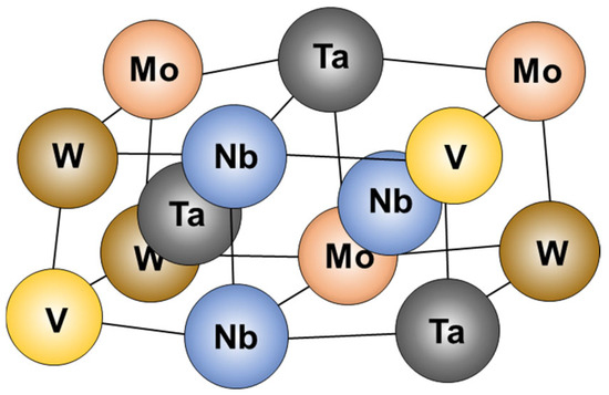
Figure 1.
Schematic illustration of BCC crystal structure of HEA WTaMoNbV with reference to calculated atomic radius of the alloying elements (Ta—143 pm, Nb—142.9 pm, W—136.7 pm, Mo—136.26 pm, and V—131.6 pm). Adapted from Ref. [32].
Hot isostatic pressing (HIP) is a thermo-mechanical treatment that can have a beneficial effect by reducing inherent defects such as pores and lack of fusion in parts produced by AM processes [33,34]. The relationship between pressure (P) and temperature (T) during the HIP cycle follows the general gas law with modifications for the specific equipment characteristics as illustrated by Equation (4), where P0 and T0 are the initial pressure and temperature, respectively.
The positive effects of HIP on pure tungsten fabricated by laser powder bed fusion (LPBF) were demonstrated by Chen et al. [35]. These effects include grain growth promotion, reduction in dislocation density, micro-crack closure, and improved thermal conductivity. The utilization of the HIP treatment in the case of HEAs was initially demonstrated by Tang et al. [36] in relation to HEA AlCoCrFeNi produced by an AM process. This study revealed that HIP treatment induced microstructural modifications, including the generation of new phases, and was able to significantly improve the alloy ductility. Similarly, Joseph et al. [37] employed HIP treatment to AM samples using a DED process to fabricate HEAs such as Al0.3CoCrFeNi, Al0.6CoCrFeNi, and Al0.85CoCrFeNi. They found that HIP treatment had a positive impact on the low Al content alloy, greatly enhancing tensile ductility. Gan et al. [38] applied HIP to HEA CoCrFeNiMn fabricated by a PBF process. They revealed that the HIP treatment can create an excellent combination of strength and ductility, mainly by reducing the density of cracks and porosity. Feng et al. [39] also demonstrated that HIP treatment applied to HEA CoCrFeNiMn produced by PBF yielded a decrease in dislocation density due to the release of residual stress, along with improved resistance to hydrogen embrittlement.
Although the general beneficial effect of HIP treatment on the physical properties of metallic AM parts is relatively well understood, the understanding of its effect on refractory HEAs produced by a PBF process is extremely limited. This study aims to evaluate the effect of HIP treatment on functional properties of HEA WTaMoNbV produced by a LPBF process.
2. Materials and Methods
2.1. Production of HEA WTaMoNbVby LPBF and HIP Treatment
The raw material for producing HEA WTaMoNbV by an LPBF process was in the form of mixed powders of pure W, Ta, Mo, Nb, and V with equal atomic proportions (20% each). The chemical composition of the elemental powders and their general appearance is presented in Table 2 and Figure 2, respectively. While the Mo powder exhibited a unique spherical appearance, other elemental powders displayed irregular shapes. The distribution range in terms of particle size was as follows: W (65–230 ), Ta (35–95 ), Mo (50–100 ), Nb (70–130 ), and V (45–100 ). The powders were mixed in a rotating chamber using a turning rate of 23 rpm for a duration of 6 h, which eventually created a well-mixed powder with a mean particle diameter of 70 μm.
Table 2.
The chemical composition of the pure elemental powders .
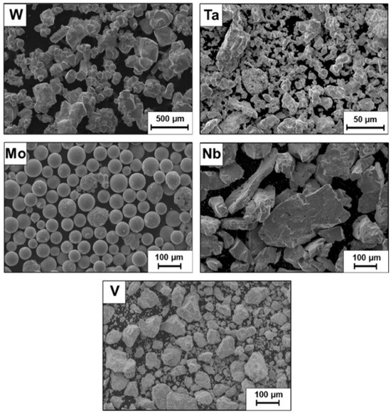
Figure 2.
General appearance of the elemental powders used as raw material to produce HEA WTaMoNbV by LPBF process.
The test specimens were produced by an LPBF system (EOS EOSINT M290, EOS, Krailing, Germany) equipped with a 400 W Nd-YAG laser (EOS, Krailing, Germany) and a pure argon gas atmosphere. The printing parameters were optimized based on our previous study [26], where we demonstrated that the energy density of 162.7 J/mm3 provides the desirable final density of 95% while minimizing inherent defects, primarily hot cracking, lack of fusion, and porosity. This optimization was achieved through systematic adjustment of laser power, scanning speed, and hatch spacing, and final parameters are presented in Table 3. It should be noted that the thickness of the printed layer was 30 µm (0.03 mm), which indicates that the mix-elemental powder has sufficient flowability to print thin layers. This was in accordance with the guidelines of Vock et al. [40] and Sutton et al. [41], who claimed that it is obligatory that the mixed powder has appropriate flowability to recoat thin layers between 20 and 100 µm. Altogether, the printed specimens produced from mix-elemental alloying powder basically showed relatively acceptable structural integration and synthesis. This comes in line with a previous study of the authors [26] and the findings of Huber et al. [24], who were able to achieve a relative density of 99.8% with the same refractory HEA using a similar LPBF process.
Table 3.
Printing parameters of the LPBF production process.
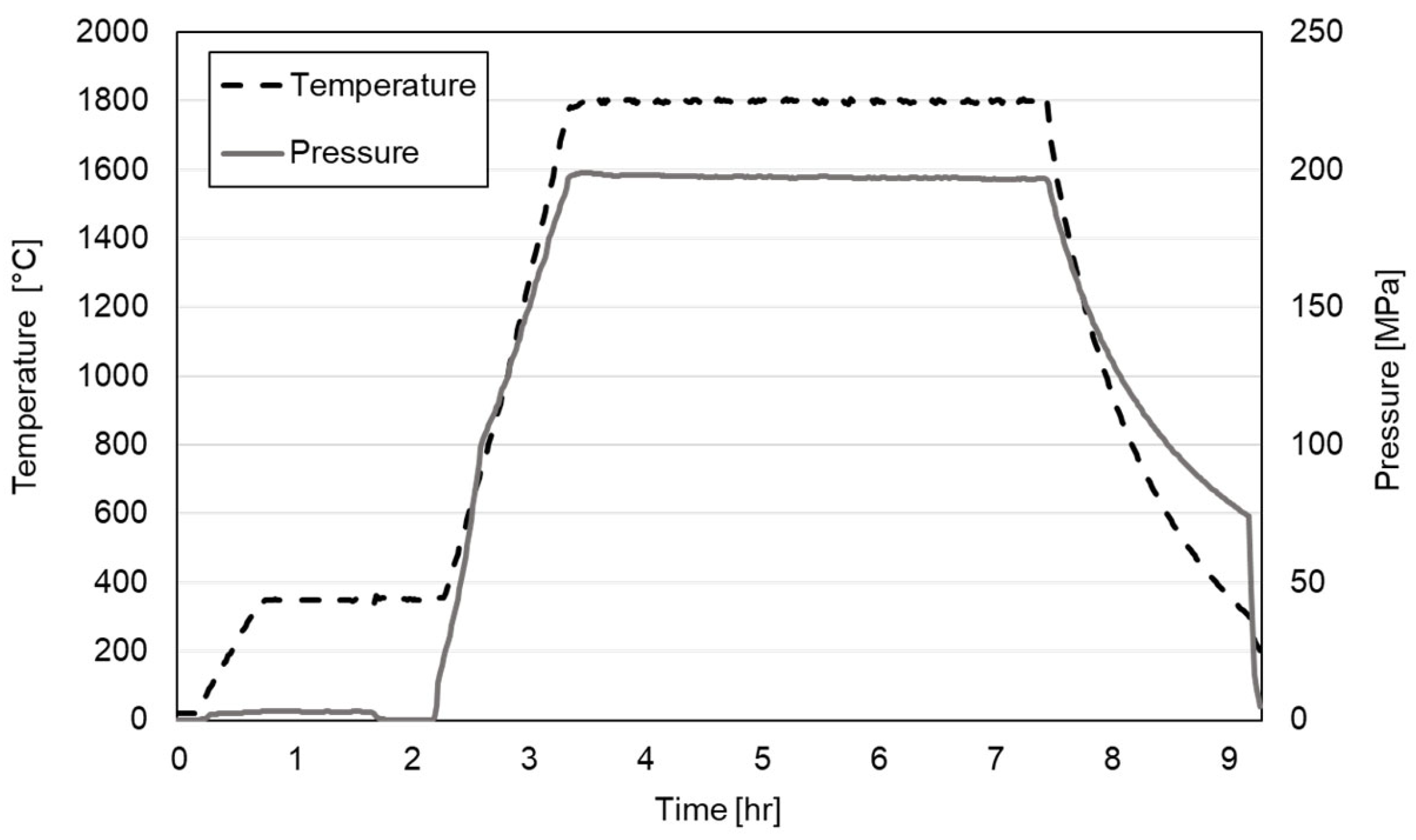
Post printing, the tested samples were subjected to a 9 h treatment using a HIP facility (QIH-15, Quintus Technologies, Västerås, Sweden). The HIP treatment encountered a maximum operating temperature of and a maximum pressure of in an argon atmosphere. The HIP parameters were selected based on the high melting temperature of the HEA ) and previous studies [35,42] while considering equipment limitations. The temperature was set at approximately 0.7 Tm of the alloy to promote sufficient atomic diffusion while avoiding excessive grain growth [43]. The HIP treatment cycle is shown in Figure 3.

Figure 3.
The cycle of the HIP treatment in terms of temperature and pressure vs. time.
2.2. Density, Surface Roughness, and Microstructure Characterization
The density of the tested samples was evaluated by an Archimedes-based method. Surface roughness measurements were conducted according to ISO 21920-2:2021 standard [44] using an SRT-6210 surface roughness tester (Landtek Instruments, Guangzhou, China) with a 5 µm tip radius. The evaluation length was 4 mm with a cut-off length of 0.8 mm. Five samples were examined for each condition, with measurements performed perpendicular to the building direction. Microstructure characterization was conducted using optical microscopy and scanning electron microscopy (SEM) with an energy-dispersive X-ray spectroscopy (EDS) sensor for localized chemical composition detection (SEM-JEOL 5600, JEOL Ltd., Tokyo, Japan; EDS—Thermo Fisher Scientific, Waltham, MA, USA) [45]. The EDS analysis was performed over multiple 250 × 250 µm areas to ensure representative sampling. For each sample, at least three different regions were analyzed to verify compositional homogeneity. The preparation of tested metallographic samples involved polishing up to 0.04 µm, and subsequent etching by immersion in Murakami’s solution, (10 g K3Fe(CN)6, 10 g NaOH, and 100 mL water), at a temperature of 90 °C for 30 s. The assessment of structural phases was conducted by X-ray diffraction (XRD) analysis using a RIGAKU-2100H X-ray diffractometer (RIGAKU-2100H, Tokyo, Japan) with CuKα operating at and a scanning rate of .
2.3. Mechanical Properties and Environmental Performance
The mechanical properties were evaluated in terms of a compression test using a Hounsfield H25KT testing machine (Tinius Olsen, Horsham, PA, USA) while employing a crosshead speed of 0.5 mm/min, The test specimens had a cylindrical shape with dimensions of a 4 mm diameter and a 14 mm length. Four specimens were tested for each condition. It should be noted that the tests were conducted without an extensometer, which may affect the precision of elastic modulus measurements. Environmental performance was examined by a standard immersion test in 1 M HCl for 14 days and by electrochemical analysis. Electrochemical evaluation was performed using a potentiodynamic polarization facility (Bio-Logic SP-200, Science Instruments, Seyssinet-Pariset, France) along with Ec-Lab software—V11.18 and a standard three-electrode cell. The potentiodynamic polarization scanning rate was set at 0.5 mV/s, while using a saturated calomel (SCE) as a reference electrode within a medium of 1 M HCl solution at ambient temperature. Three samples were evaluated for each condition. Prior to the electrochemical analysis, the tested samples were cleaned in an ultrasonic bath for 5 min followed by washing with alcohol and air drying.
3. Results
The effect of HIP on surface morphology is illustrated in Figure 4, which reveals that the surface roughness of the specimen post HIP treatment was relatively reduced compared to the as-printed sample. The comparatively smooth post HIP surface topography is clearly demonstrated in the profile views of the tested specimens, as shown in Figure 4a,c. This result was also supported by the actual measurements of the surface roughness and density, as shown in Table 4. Accordingly, the surface roughness of the post HIP specimen was equivalent to roughness grade N10, while that of the as-printed sample was equivalent to N11 [46]. In terms of densification, the post HIP specimen showed a slight increase in density compared to the as-printed sample.
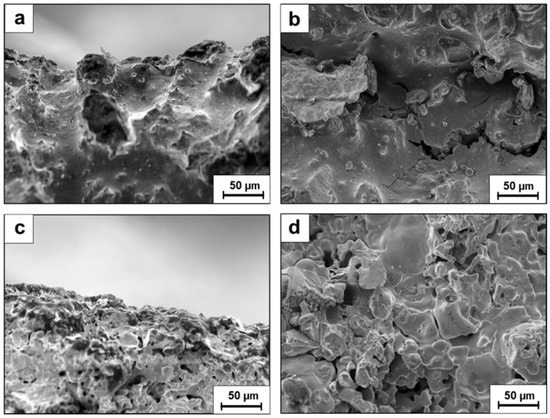
Figure 4.
External surface appearance in as-printed condition (a,b) and post HIP treatment (c,d).
Table 4.
Average surface roughness () and density ().
In terms of chemical composition, the effect of HIP treatment was minor, as shown in Table 5. Furthermore, both samples (with and without HIP treatment) showed a depletion in W compared to the designated 20 at% that was added to the original HEA feedstock mix powder. The general macrostructure of HEA WTaMoNbV in as-printed and post HIP treatment is shown in Figure 5. This reveals that the typical AM melt pool boundaries that were present in the as-printed sample had disappeared post HIP treatment. Furthermore, the inherent morphological differences between the XY and the XZ planes versus printing direction were diminished post HIP treatment.
Table 5.
Chemical composition (at%) by EDS analysis of HEA WTaMoNbV in as-printed and post HIP treatment.
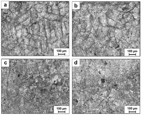
Figure 5.
General macrostructure of HEA WTaMoNbV obtained by optical microscopy (a) and (b)—XY and XZ planes, respectively, in as-printed sample and (c) and (d) post HIP treatment—XY and XZ planes, respectively.
XRD analysis of as-printed and post HIP treatment samples showed similar phase compositions to those presented in Figure 6. Both alloys consist of a BCC matrix with space group Im-3m along with two secondary compounds, NbTa intermetallic phase and W-based particles with the same space group structure. The relatively weak intensity of W-based peaks in the XRD pattern can be attributed to the lower overall concentration of W in the alloy compared to the nominal composition and the presence of W primarily in isolated particles rather than as a uniformly distributed phase in the matrix.
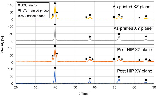
Figure 6.
XRD analysis of HEA WTaMoNbV in as-printed and post HIP treatment.
Both tested alloys showed insignificant preferred orientation of the BCC matrix. This can be explained by the fact that all the [200] peaks were not strong and the intensity ratio of [200] versus [110] peaks were similar for both the XZ and XY planes. The variations in phase composition between XY and XZ directions can be attributed to the inherent directional solidification characteristic of the LPBF process. The layer-by-layer building process creates thermal gradients primarily in the build direction (Z), leading to elongated grains and potential texture differences between planes.
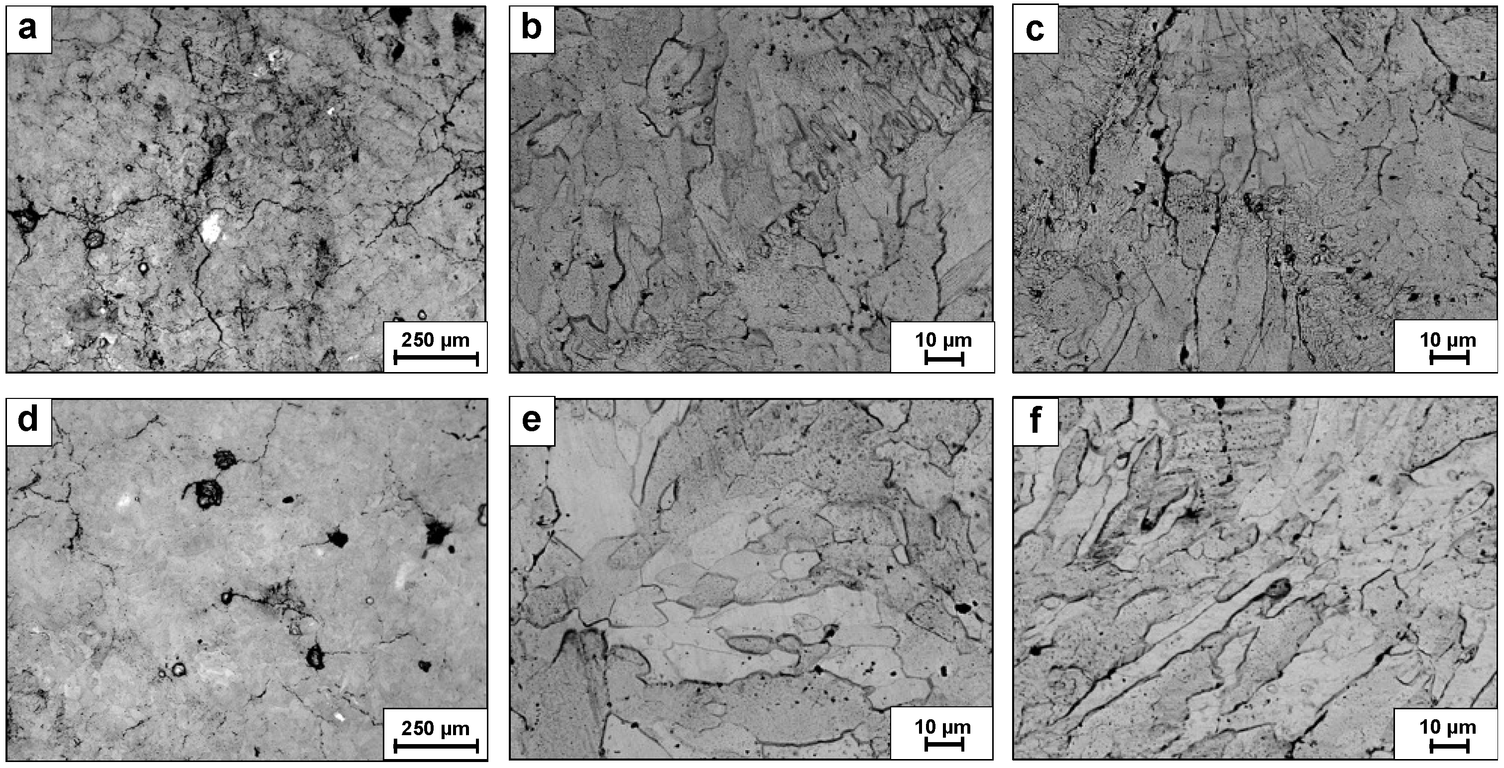
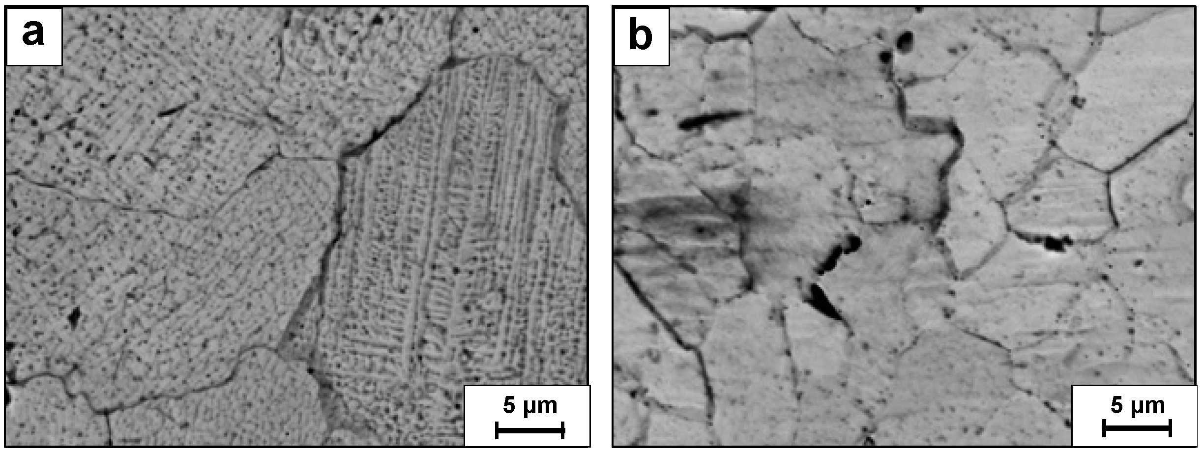
The general microstructure of as-printed and post HIP treatment samples, as obtained by SEM analysis, is shown in Figure 7, while a magnified view is presented in Figure 8. The as-printed specimen exhibits a relatively fine grain structure along with sub-grains and dendritic morphology (Figure 8a), while the post HIP treatment alloy showed a homogenized texture with elongated grain structure and significantly reduced dendritic morphology (Figure 8b). Additionally, melt pool boundaries were visible only in the case of the as-printed specimen.

Figure 7.
Typical microstructure of WTaMoNV alloy by SEM (a,b) in as-printed conditions—XY plane, (c) in as-printed conditions—XZ planes, r (d,e) post HIP treatment—XY plane, (f) post HIP treatment—XZ planes.

Figure 8.
Highly magnified microstructure of WTaMoNV alloy by SEM (a) in as-printed conditions and (b) post HIP treatment.
Localized chemical composition analysis related to the magnified view of the post HIP sample presented in Figure 9 is shown in Table 6. This clearly reveals the presence of un-melted W particles amalgamated within the alloy matrix. The presence of these un-melted W particles is primarily attributed to tungsten’s significantly higher melting point (3422 °C) compared to other constituent elements, which range from 1910 °C (V) to 3017 °C (Ta). It is believed that during the HIP process, these W particles were able to grow and, consequently, lead to a depletion of W in neighboring areas. The deviation in W and V concentrations can be attributed to two main factors, as previously observed in our work [26]: (i) the presence of un-melted W particles creating local composition variations, and (ii) the relatively high vapor pressure of V at the processing temperature leading to some preferential evaporation during printing.
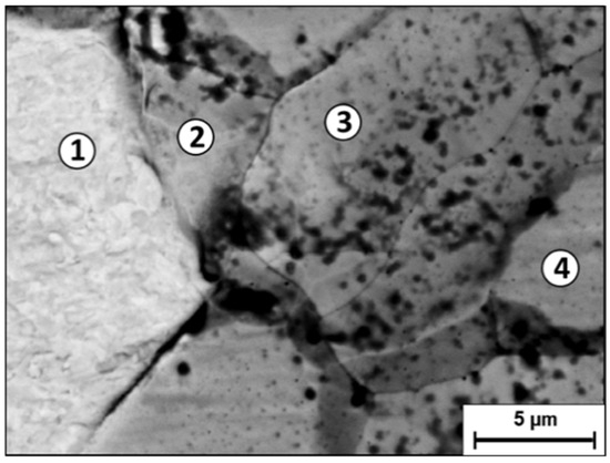
Figure 9.
Spot chemical analysis of the post HIP treatment sample obtained by EDS-SEM.
Table 6.
Chemical composition (at%) at various locations shown in Figure 9.
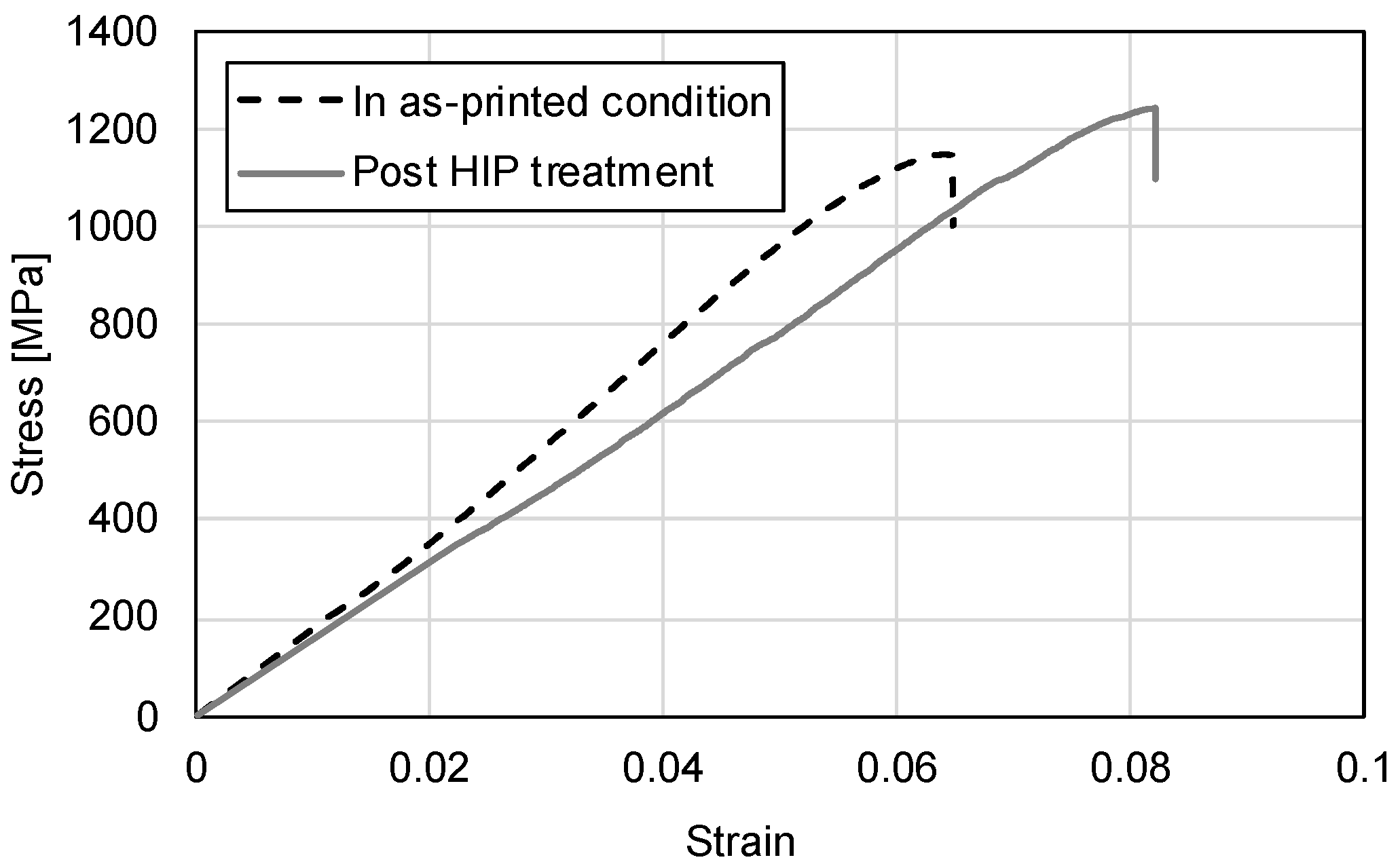
The mechanical properties of as-printed and post HIP treatment alloys in terms of a compression test are shown in Figure 10 and Table 7. Both conditions exhibited predominantly elastic behavior with very limited plastic deformation. The apparent strain to failure values, when corrected for elastic deformation using the parallel line method, show negligible plastic deformation (<1%) prior to failure, confirming the brittle nature of the material. However, the post-HIP treatment alloy exhibits higher ultimate compression stress (UCS) and relatively increased ductility compared to the as-printed condition. Fractography analysis revealed that both alloys displayed a brittle fracture with a trans-granular morphology, as shown in Figure 11. Additionally, in the case of the as-printed alloy (Figure 11a), there were clear signs of un-melted powder particles embedded in the fracture surface.
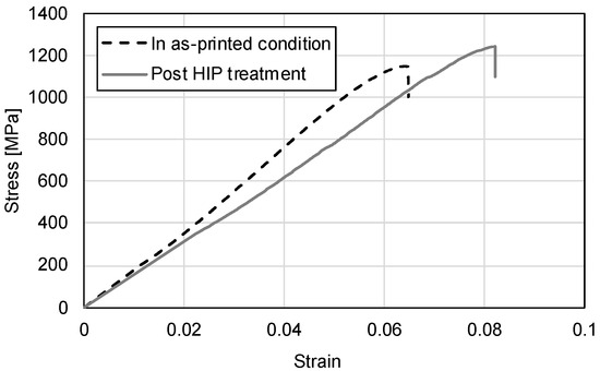
Figure 10.
Typical stress–strain curves of as-printed and post HIP treatment samples as obtained by compression test.
Table 7.
Numerical results derived from compression test presented in Figure 11.
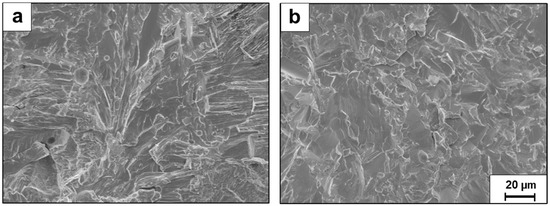
Figure 11.
Fractography analysis of HEA WTaMoNbV after compression test: (a) as-printed alloy and (b) post HIP treatment alloy.
The environmental performance of the tested alloys in terms of an immersion test in 1 M HCl for 14 days indicated that both alloys have an acceptable degradation rate. However, the severeness of their pitting attack was significantly different, as shown in Figure 12. Accordingly, the pitting density in the as-printed alloy was compared to only in the post HIP treatment alloy. In addition, the size of the pitting holes in the as-printed alloy (Figure 12b) was significantly larger compared to that of the post HIP treatment alloy (Figure 12d). Another interesting finding in the as-printed alloy was the presence of structural cracks at the bottom side of the large pit, which can induce intergranular corrosion as well as premature mechanical failure.
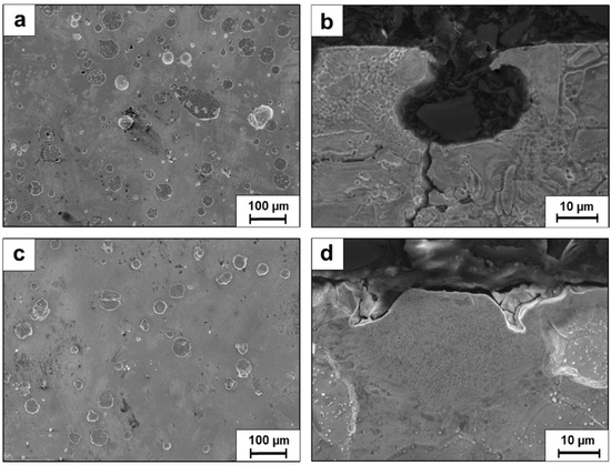
Figure 12.
Pitting attack of HEA WTaMoNbV after 14 days of immersions in 1 M HCl solution: (a,b) as-printed alloy and (c,d) post HIP treatment alloy.
Cyclic potentiodynamic polarization analysis in 1 M HCl solution clearly demonstrates the substantial improvement in environmental behavior of the post HIP treatment sample, as shown in Figure 13. While both alloys exhibit a similar active–passive transition behavior [47], the polarization curve of the post HIP treatment sample was strongly shifted to significantly lower current densities, which indicates relatively improved passivation capabilities. In terms of Taffel extrapolation (Table 8), both alloys display excellent corrosion resistance, as anticipated from HEA WTaMoNbV, with a slight advantage attributed to the post HIP treatment sample.
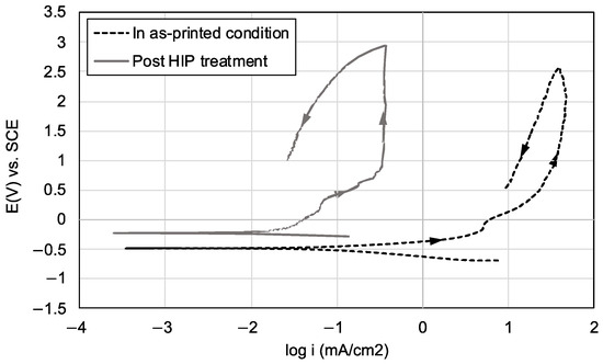
Figure 13.
Cyclic potentiodynamic polarization analysis in 1 M HCl solution of HEA WTaMoNbV in as-printed and post HIP treatment.
Table 8.
Electrochemical parameters derived from the potentiodynamic polarization curves shown in Figure 13.
4. Discussion
This study clearly demonstrates the beneficial effect of HIP treatment on functional properties of refractory HEA WTaMoNbV produced by AM technology in the form of an LPBF process. This favorable effect can be attributed to improvements in both bulk properties and surface characteristics. The bulk properties were enhanced through the elimination of sub-grain structure and reduction in inherent printing defects, while surface quality improved from grade N11 (as-printed) to N10 (post HIP).
Regarding the bulk properties, while both the as-printed alloy and post HIP alloy exhibited similar phase compositions (BCC matrix with two main secondary phases—NbTa and W-based), their structural morphology and defects differed significantly. The HIP treatment increased density from 11.27 to 11.38 g/cm3 and substantially reduced internal cracking, as evidenced by SEM examination. This efficient elimination of internal cracking aligns with the findings of Vilanova et al. [48] for Ni-base superalloy and Grech et al. [23] for 316L stainless steel. However, surface-connected defects remained relatively unchanged due to insufficient pressure differential development at these locations.
The mechanical properties showed notable improvements in post HIP treatment. The UCS increased by 11.5% (from 1094 to 1220 MPa), while ductility improved by 29% (from 6.2% to 8.0% strain). These improvements can be attributed to several microstructural modifications: (i) reduction in porosity, (ii) elimination of sub-grain boundaries, (iii) reducing barriers to dislocation motion, (iv) more homogeneous distribution of elements, and (v) reduction in internal stress. The apparent decrease in elastic modulus post-HIP, despite reduced porosity, likely results from reduced internal stresses and modified phase distribution. The enhanced ductility primarily stems from the elimination of sub-grain boundaries, reducing obstacles to dislocation flow. These improvements align with findings by Gan et al. [38] for HEA CoCrFeNiMn and Fiocchi et al. [49] for CoCuFeMnNiTi0.13 following LPBF processing.
In addition, although the comparative fractography analysis indicated that both alloys displayed a brittle fracture with a trans-granular morphology, there were clear signs of un-melted powder particles imbedded in the as-printed alloy that were nearly not present in the post HIP alloy. The un-melted compounds (also found by Huber et al. [24] and referred to as “undissolved particles”) can generate areas with increased stress concentration that can subsequently have a detrimental effect on the mechanical properties.
The enhancement of the surface quality by the HIP treatment also has a beneficial effect on corrosive resistance. The superior environmental behavior of the post HIP alloy was manifested by a significant reduction in pitting density—by more than 70% compared to the as-printed alloy (, respectively). This result was also supported by the potentiodynamic polarization analysis and was in line with the findings of Ren et al. [50] in relation to the Ti–Ni alloy produced by a LPBF process. The positive effect of HIP on the corrosion mechanism is shown schematically in Figure 14. Accordingly, the elimination of the sub-grain structure, along with the reduction in printing imperfections, leads to reduced pitting density and pitting size.
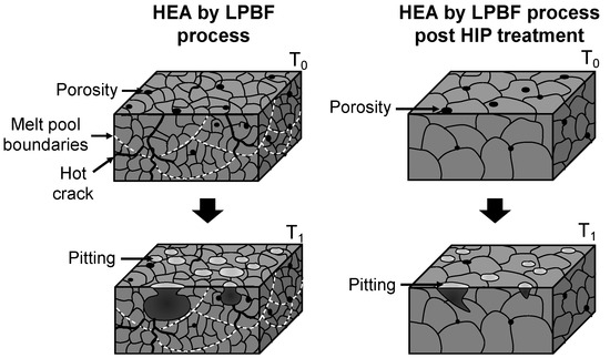
Figure 14.
Schematic illustration of corrosion mechanism of HEA WTaMoNbV in as-printed condutuin and post HIP treatment.
Altogether it is evident that the HIP treatment was able to rectify a large amount of the inherent LPBF printing defects of refractory HEA WTaMoNbV and, consequently, to improve the functional behavior of this alloy in terms of physical properties and environmental behavior. The inherent LPBF printing defects were mainly related to increased surface roughness and bulk defects in the form of internal cracking and un-melted compounds. The fact that HIP treatment can efficiently eliminate internal cracking comes in line with the findings of Vilanova et al. [48] in Ni-base superalloy and Grech et al. [45] in 316L stainless steel. The beneficial effect of HIP treatment on the mechanical properties of refractory HEA WTaMoNbV in terms of ductility and strength were also recorded in the findings of Gan et al. [38] for HEA CoCrFeNiMn and Fiocchi et al. [49] for CoCuFeMnNiTi0.13 where HIP treatment was employed after a LPBF process. Further experimental work is required to optimize the tailoring process of the HIP treatment related to refractory HEAs. Additionally, the optimization of the LPBF process in terms of printing parameters is crucial for reducing internal cracks and surface roughness.
5. Conclusions
- (a)
- The HIP treatment clearly improved the structural integrity of LPBF-produced WTaMoNbV HEA, increasing density from 11.27 to 11.38 g/cm3 and enhancing surface quality from grade N11 to N10. This treatment effectively eliminated sub-grain boundaries and significantly reduced internal cracking while maintaining the fundamental BCC structure.
- (b)
- Mechanical properties showed notable enhancement post-HIP treatment, with an 11.5% increase in ultimate compression strength (1220 vs. 1094 MPa) and 29% improvement in ductility (8.0% vs. 6.2% strain). Environmental performance also improved significantly, demonstrated by a 71.7% reduction in pitting density (from 34,155 to 9677 pits/cm2).
- (c)
- The above improvements can indicate that HIP treatment can be related as an effective post-processing method for refractory HEAs produced by LPBF process. Nevertheless, further optimization of both HIP and LPBF parameters is essential to obtain additional enhancements.
Author Contributions
Conceptualization: A.L. and E.A.; methodology: A.S. and E.A.; validation: A.L., M.B. and Z.C.; investigation: T.R., A.L., M.B., Z.C. and A.S.; writing—original draft preparation: T.R. and E.A.; supervision: A.S. and E.A. All authors have read and agreed to the published version of the manuscript.
Funding
This research received no external funding.
Data Availability Statement
The raw data supporting the conclusions of this article will be made available by the authors on request.
Acknowledgments
The authors would like to thank James Shipley and Johannes Gårdstam from Quintus Technologies AB, Västerås, Sweden, for conducting the hot isostatic pressing (HIP) treatment post LPBF process, and the Kreitman School for Advanced Studies at Ben-Gurion University of the Negev for their financial contribution in support of this research.
Conflicts of Interest
The authors declare no conflicts of interest.
References
- Poulia, A.; Georgatis, E.; Lekatou, A.; Karantzalis, A.E. Microstructure and wear behavior of a refractory high entropy alloy. Int. J. Refract. Met. Hard Mater. 2016, 57, 50–63. [Google Scholar] [CrossRef]
- Senkov, O.N.; Wilks, G.B.; Miracle, D.B.; Chuang, C.P.; Liaw, P.K. Refractory high-entropy alloys. Intermetallics 2010, 18, 1758–1765. [Google Scholar] [CrossRef]
- Torralba, J.M.; Alvaredo, P.; García-Junceda, A. High-entropy alloys fabricated via powder metallurgy. A critical review. Powder Metall. 2019, 62, 84–114. [Google Scholar] [CrossRef]
- Zhang, Y.; Zuo, T.T.; Tang, Z.; Gao, M.C.; Dahmen, K.A.; Liaw, P.K.; Lu, Z.P. Microstructures and properties of high-entropy alloys. Prog. Mater. Sci. 2014, 61, 1–93. [Google Scholar] [CrossRef]
- Fujieda, T.; Chen, M.; Shiratori, H.; Kuwabara, K.; Yamanaka, K.; Koizumi, Y.; Chiba, A.; Watanabe, S. Mechanical and corrosion properties of CoCrFeNiTi-based high-entropy alloy additive manufactured using selective laser melting. Addit. Manuf. 2019, 25, 412–420. [Google Scholar] [CrossRef]
- Guo, J.; Goh, M.; Zhu, Z.; Lee, X.; Nai, M.L.S.; Wei, J. On the machining of selective laser melting CoCrFeMnNi high-entropy alloy. Mater. Des. 2018, 153, 211–220. [Google Scholar] [CrossRef]
- Luo, S.; Gao, P.; Yu, H.; Yang, J.; Wang, Z.; Zeng, X. Selective laser melting of an equiatomic AlCrCuFeNi high-entropy alloy: Processability, non-equilibrium microstructure and mechanical behavior. J. Alloys Compd. 2019, 771, 387–397. [Google Scholar] [CrossRef]
- Ron, T.; Shirizly, A.; Aghion, E. Additive Manufacturing Technologies of High Entropy Alloys (HEA): Review and Prospects. Materials 2023, 16, 2454. [Google Scholar] [CrossRef]
- Niu, P.D.; Li, R.D.; Yuan, T.C.; Zhu, S.Y.; Chen, C.; Wang, M.B.; Huang, L. Microstructures and properties of an equimolar AlCoCrFeNi high entropy alloy printed by selective laser melting. Intermetallics 2019, 104, 24–32. [Google Scholar] [CrossRef]
- Peyrouzet, F.; Hachet, D.; Soulas, R.; Navone, C.; Godet, S.; Gorsse, S. Selective laser melting of Al0. 3CoCrFeNi high-entropy alloy: Printability, microstructure, and mechanical properties. JOM 2019, 71, 3443–3451. [Google Scholar] [CrossRef]
- Chao, Q.; Guo, T.; Jarvis, T.; Wu, X.; Hodgson, P.; Fabijanic, D. Direct laser deposition cladding of AlxCoCrFeNi high entropy alloys on a high-temperature stainless steel. Surf. Coat. Technol. 2017, 332, 440–451. [Google Scholar] [CrossRef]
- Chen, X.; Yan, L.; Karnati, S.; Zhang, Y.; Liou, F. Fabrication and characterization of Al x CoFeNiCu1− x high entropy alloys by laser metal deposition. Coatings 2017, 7, 47. [Google Scholar] [CrossRef]
- Vogiatzief, D.; Evirgen, A.; Pedersen, M.; Hecht, U. Laser powder bed fusion of an Al-Cr-Fe-Ni high-entropy alloy produced by blending of prealloyed and elemental powder: Process parameters, microstructures and mechanical properties. J. Alloys Compd. 2022, 918, 165658. [Google Scholar] [CrossRef]
- Han, T.; Liu, Y.; Yang, D.; Qu, N.; Liao, M.; Lai, Z.; Jiang, M.; Zhu, J. Effect of annealing on microstructure and mechanical properties of AlCrFe2Ni2 medium entropy alloy fabricated by laser powder bed fusion additive manufacturing. Mater. Sci. Eng. A 2022, 839, 142868. [Google Scholar] [CrossRef]
- Zhang, M.; Zhou, X.; Wang, D.; Zhu, W.; Li, J.; Zhao, Y.F. AlCoCuFeNi high-entropy alloy with tailored microstructure and outstanding compressive properties fabricated via selective laser melting with heat treatment. Mater. Sci. Eng. A 2019, 743, 773–784. [Google Scholar] [CrossRef]
- Lin, D.; Xu, L.; Jing, H.; Han, Y.; Zhao, L.; Minami, F. Effects of annealing on the structure and mechanical properties of FeCoCrNi high-entropy alloy fabricated via selective laser melting. Addit. Manuf. 2020, 32, 101058. [Google Scholar] [CrossRef]
- Pan, J.; Dai, T.; Lu, T.; Ni, X.; Dai, J.; Li, M. Microstructure and mechanical properties of Nb25Mo25Ta25W25 and Ti8Nb23Mo23Ta23W23 high entropy alloys prepared by mechanical alloying and spark plasma sintering. Mater. Sci. Eng. A 2018, 738, 362–366. [Google Scholar] [CrossRef]
- Han, Z.D.; Luan, H.W.; Liu, X.; Chen, N.; Li, X.Y.; Shao, Y.; Yao, K.F. Microstructures and mechanical properties of TixNbMoTaW refractory high-entropy alloys. Mater. Sci. Eng. A 2018, 712, 380–385. [Google Scholar] [CrossRef]
- Kunce, I.; Polanski, M.; Bystrzycki, J. Microstructure and hydrogen storage properties of a TiZrNbMoV high entropy alloy synthesized using Laser Engineered Net Shaping (LENS). Int. J. Hydrogen Energy 2014, 39, 9904–9910. [Google Scholar] [CrossRef]
- Dobbelstein, H.; Thiele, M.; Gurevich, E.L.; George, E.P.; Ostendorf, A. Direct Metal Deposition of Refractory High Entropy Alloy MoNbTaW. Phys. Procedia 2016, 83, 624–633. [Google Scholar] [CrossRef]
- Moorehead, M.; Bertsch, K.; Niezgoda, M.; Parkin, C.; Elbakhshwan, M.; Sridharan, K.; Zhang, C.; Thoma, D.; Couet, A. High-throughput synthesis of Mo-Nb-Ta-W high-entropy alloys via additive manufacturing. Mater. Des. 2020, 187, 108358. [Google Scholar] [CrossRef]
- Melia, M.A.; Whetten, S.R.; Puckett, R.; Jones, M.; Heiden, M.J.; Argibay, N.; Kustas, A.B. High-throughput additive manufacturing and characterization of refractory high entropy alloys. Appl. Mater. Today 2020, 19, 100560. [Google Scholar] [CrossRef]
- Xiao, B.; Liu, H.; Jia, W.; Wang, J.; Zhou, L. Cracking suppression in selective electron beam melted WMoTaNbC refractory high-entropy alloy. J. Alloys Compd. 2023, 948, 169787. [Google Scholar] [CrossRef]
- Huber, F.; Bartels, D.; Schmidt, M. In-situ alloy formation of a WMoTaNbV refractory metal high entropy alloy by laser powder bed fusion (PBF-LB/M). Materials 2021, 14, 3095. [Google Scholar] [CrossRef] [PubMed]
- Zhang, H.; Zhao, Y.; Huang, S.; Zhu, S.; Wang, F.; Li, D. Manufacturing and analysis of high-performance refractory high-entropy alloy via selective laser melting (SLM). Materials 2019, 12, 720. [Google Scholar] [CrossRef] [PubMed]
- Ron, T.; Leon, A.; Popov, V.; Strokin, E.; Eliezer, D.; Shirizly, A.; Aghion, E. Synthesis of Refractory High-Entropy Alloy WTaMoNbV by Powder Bed Fusion Process Using Mixed Elemental Alloying Powder. Materials 2022, 15, 4043. [Google Scholar] [CrossRef]
- Karimi, J.; Kollo, L.; Rahmani, R.; Ma, P.; Jia, Y.D.; Prashanth, K.G. Selective laser melting of in-situ CoCrFeMnNi high entropy alloy: Effect of remelting. J. Manuf. Process. 2022, 84, 55–63. [Google Scholar] [CrossRef]
- Lin, D.; Xu, L.; Li, X.; Jing, H.; Qin, G.; Pang, H.; Minami, F. A Si-containing FeCoCrNi high-entropy alloy with high strength and ductility synthesized in situ via selective laser melting. Addit. Manuf. 2020, 35, 101340. [Google Scholar] [CrossRef]
- Haase, C.; Tang, F.; Wilms, M.B.; Weisheit, A.; Hallstedt, B. Combining thermodynamic modeling and 3D printing of elemental powder blends for high-throughput investigation of high-entropy alloys—Towards rapid alloy screening and design. Mater. Sci. Eng. A 2017, 688, 180–189. [Google Scholar] [CrossRef]
- Xiong, W.; Du, Y.; Liu, Y.; Huang, B.Y.; Xu, H.H.; Chen, H.L.; Pan, Z. Thermodynamic assessment of the Mo–Nb–Ta system. Calphad 2004, 28, 133–140. [Google Scholar] [CrossRef]
- Ravi, C.; Panigrahi, B.K.; Valsakumar, M.C.; van de Walle, A. First-principles calculation of phase equilibrium of V-Nb, V-Ta, and Nb-Ta alloys. Phys. Rev. B—Condens. Matter Mater. Phys. 2012, 85, 054202. [Google Scholar] [CrossRef]
- Miracle, D.B.; Senkov, O.N. A critical review of high entropy alloys and related concepts. Acta Mater. 2017, 122, 448–511. [Google Scholar] [CrossRef]
- Leon, A.; Levy, G.K.; Ron, T.; Shirizly, A.; Aghion, E. The effect of hot isostatic pressure on the corrosion performance of Ti-6Al-4 V produced by an electron-beam melting additive manufacturing process. Addit. Manuf. 2020, 33, 101039. [Google Scholar] [CrossRef]
- Dolev, O.; Ron, T.; Aghion, E.; Shirizly, A. Effect of HIP Defects on the Mechanical Properties of Additive Manufactured Ti6Al4V Alloy. Metals 2022, 12, 1210. [Google Scholar] [CrossRef]
- Chen, J.; Li, K.; Wang, Y.; Xing, L.; Yu, C.; Liu, H.; Ma, J.; Liu, W.; Shen, Z. The effect of hot isostatic pressing on thermal conductivity of additively manufactured pure tungsten. Int. J. Refract. Met. Hard Mater. 2020, 87, 105135. [Google Scholar] [CrossRef]
- Tang, Z.; Senkov, O.N.; Parish, C.M.; Zhang, C.; Zhang, F.; Santodonato, L.J.; Wang, G.; Zhao, G.; Yang, F.; Liaw, P.K. Tensile ductility of an AlCoCrFeNi multi-phase high-entropy alloy through hot isostatic pressing (HIP) and homogenization. Mater. Sci. Eng. A 2015, 647, 229–240. [Google Scholar] [CrossRef]
- Joseph, J.; Hodgson, P.; Jarvis, T.; Wu, X.; Stanford, N.; Fabijanic, D.M. Effect of hot isostatic pressing on the microstructure and mechanical properties of additive manufactured AlxCoCrFeNi high entropy alloys. Mater. Sci. Eng. A 2018, 733, 59–70. [Google Scholar] [CrossRef]
- Gan, G.; Yang, B.; Zhang, X.; Zhu, Z.; Chen, B.; Gou, G. Tuning the mechanical properties of powder bed fusion printed CoCrFeNiMn high-entropy alloys by annealing and hot isostatic pressing. J. Alloys Compd. 2023, 946, 169376. [Google Scholar] [CrossRef]
- Feng, S.; Ai, Z.; He, J.; Yang, B.; Gou, G.; Han, L. Effect of Annealing and Hot Isostatic Pressing on the Structure and Hydrogen Embrittlement Resistance of Powder-Bed Fusion-Printed CoCrFeNiMn High-Entropy Alloys. Metals 2023, 13, 630. [Google Scholar] [CrossRef]
- Vock, S.; Klöden, B.; Kirchner, A.; Weißgärber, T.; Kieback, B. Powders for powder bed fusion: A review. Prog. Addit. Manuf. 2019, 4, 383–397. [Google Scholar] [CrossRef]
- Sutton, A.T.; Kriewall, C.S.; Leu, M.C.; Newkirk, J.W. Powder characterisation techniques and effects of powder characteristics on part properties in powder-bed fusion processes. Virtual Phys. Prototyp. 2017, 12, 3–29. [Google Scholar] [CrossRef]
- Kim, Y.; Kim, M.; Lee, K. 1.45 GPa ultrastrong cryogenic strength with superior impact toughness in the in-situ nano oxide reinforced CrMnFeCoNi high-entropy alloy matrix nanocomposite manufactured by laser powder bed fusion. J. Mater. Sci. Technol. 2022, 97, 10–19. [Google Scholar] [CrossRef]
- Laleh, M.; Sadeghi, E.; Revilla, R.I.; Chao, Q.; Haghdadi, N.; Hughes, A.E.; Xu, W.; De Graeve, I.; Qian, M.; Gibson, I.; et al. Heat treatment for metal additive manufacturing. Prog. Mater. Sci. 2023, 133, 101051. [Google Scholar] [CrossRef]
- ISO 21920-2:2021; Geometrical Product Specifications (GPS)—Surface Texture: Profile. Part 2: Terms, Definitions and Surface Texture Parameters. ISO: Geneva, Switzerland, 2022.
- Kaya, A.A.; Uzan, P.; Eliezer, D.; Aghion, E. Electron microscopical investigation of as cast AZ91D alloy. Mater. Sci. Technol. 2000, 16, 1001–1006. [Google Scholar] [CrossRef]
- Gong, Y.; Xu, J.; Buchanan, R.C. Surface roughness: A review of its measurement at micro-/nano-scale. Phys. Sci. Rev. 2018, 3, 20170057. [Google Scholar] [CrossRef]
- Itzhak, D.; Aghion, E. An anodic behaviour study of an analogical sintered system of austenitic stainless steel in H2SO4 solution. Corros. Sci. 1984, 24, 145–149. [Google Scholar] [CrossRef]
- Vilanova, M.; Garciandia, F.; Sainz, S.; Jorge-Badiola, D.; Guraya, T.; Sebastian, M.S. The limit of hot isostatic pressing for healing cracks present in an additively manufactured nickel superalloy. J. Mater. Process. Technol. 2022, 300, 117398. [Google Scholar] [CrossRef]
- Fiocchi, J.; Biffi, C.A.; Elnemr, M.; Shipley, J.; Tuissi, A.; Casati, R. Hot isostatic pressing and heat treatments of LPBFed CoCuFeMnNiTi0. 13 high-entropy alloy: Microstructure and mechanical properties. J. Mater. Res. Technol. 2023, 26, 9127–9138. [Google Scholar] [CrossRef]
- Ren, D.; Zhang, L.; Liu, Y.; Ji, H.; Li, S.; Jin, W.; Lei, J. Effect of hot isostatic pressing on the mechanical and corrosive properties of Ti–Ni alloy fabricated by selective laser melting. J. Mater. Res. Technol. 2023, 26, 4595–4605. [Google Scholar] [CrossRef]


Disclaimer/Publisher’s Note: The statements, opinions and data contained in all publications are solely those of the individual author(s) and contributor(s) and not of MDPI and/or the editor(s). MDPI and/or the editor(s) disclaim responsibility for any injury to people or property resulting from any ideas, methods, instructions or products referred to in the content. |
© 2025 by the authors. Licensee MDPI, Basel, Switzerland. This article is an open access article distributed under the terms and conditions of the Creative Commons Attribution (CC BY) license (https://creativecommons.org/licenses/by/4.0/).