Abstract
The temperature gradient inside a tundish leads to the uneven density distribution of molten steel, resulting in thermal buoyancy, which has a significant impact on the motion of inclusion particles. Based on practice data and necessary assumptions, a three-dimensional model of a tundish considering non-uniform thermal transfer was established. The flow and temperature distribution were studied, and the changes in inclusion removal rate were compared with different casting speeds and temperature reduction rates using computational fluid dynamics simulation. It was observed that, when the inlet temperature is higher, the molten steel floats up under the action of thermal buoyancy, which can form a horizontal stream behind the weir. While the inlet temperature is lower, the horizontal stream cannot be maintained, resulting in a decrease in the removal rate of inclusions. Increasing the casting speed will increase the velocity of the molten steel in the tundish, make it easier to shorten the temperature difference between the inlet and outlet, and reduce the removal rate of inclusions. When formulating production processes, the impact of thermal buoyancy on the flow field should be taken into account.
1. Introduction
The tundish is a key facility in the continuous casting process. The flow field characteristics inside the tundish and the motion of inclusions directly affect the quality of the cast billet [1,2,3]. Inclusions can have adverse effects on the mechanical properties, surface quality, and processing performance of billets [4,5]. The flow field is influenced by various factors, such as flow control devices, casting speed, and tundish heat transfer [6,7,8,9,10]. Therefore, it is necessary to thoroughly study how to control these factors to optimize the flow field and inclusion removal.
Previous studies have indicated that the flow and heat transfer of molten steel in the tundish can affect the quality of the billet. Zhang et al. [11] studied the impact of the ladle shroud on the fluid inside the tundish and designed a trumpet-shaped ladle shroud to achieve a relatively calm melt bath. Rosa et al. [12] pointed out that fluctuation of the temperature inside the tundish can affect the occurrence of corner cracks. Sheng et al. [13] studied the effect of thermal buoyancy on residence time distribution in the tundish through physical and numerical simulations and evaluated the influence of different flow control devices on the flow field and heat loss in the tundish. Xie et al. [14] conducted three-dimensional numerical simulations on the use of a swirling flow generator in the tundish and round billet mold and summarized the effects of the swirling flow generator on the flow field and temperature field. Fang et al. [15] studied the optimization effect of various flow control devices on the flow, heat transfer, and inclusion removal behavior of the five flow tundish through physical simulation. Yang et al. [16] and Dou et al. [17] established physical and mathematical models to describe the fluid flow and heat transfer inside the tundish with induction heating, and studied the effects of electromagnetic induction heating on the flow field, temperature field, and inclusion movement. Zhu et al. [18] compared the similarities and differences between isothermal and non-isothermal water models and pointed out that the fluid flow inside the tundish has non-isothermal characteristics, and the simulation results under non-isothermal conditions can better reflect the actual flow and heat transfer behavior of the molten steel inside the tundish.
Temperature gradient inside the tundish leads to uneven density distribution of molten steel, resulting in thermal buoyancy [19]. Thermal buoyancy has a significant impact on fluid flow and the motion behavior of non-metallic inclusion particles. However, the influence of thermal buoyancy has not received sufficient attention before. Previously, molten steel was usually treated as a liquid with a constant density. The influence of thermal buoyancy on the flow field and inclusion removal inside the tundish still needs further research. In the continuous casting process, the temperature of the molten steel in the tundish is high, the metallurgical reactions are complex and unobservable. It is difficult to directly obtain the multiphase flow behavior and non-metallic inclusion particle movement in the tundish through field experiments [20,21,22,23,24]. Computational fluid dynamics (CFD) has been widely used in tundish metallurgy due to its advantages of not being affected by external factors, being easy to operate, and having less equipment [25,26,27,28,29]. Numerical simulation can simulate fluid flow and inclusion motion behavior under different temperature gradients, providing an important basis for understanding their influencing mechanisms.
Based on practice data and necessary assumptions, a three-dimensional model of the tundish considering non-uniform thermal transfer was established. This study investigates the changes in the flow field, temperature field, and inclusion removal behavior inside the tundish under different process parameters through CFD simulation, having positive significance for improving steel product quality, reducing production costs, minimizing environmental pollution, and promoting process innovation.
2. Numerical Model
2.1. Model Parameters and Assumptions
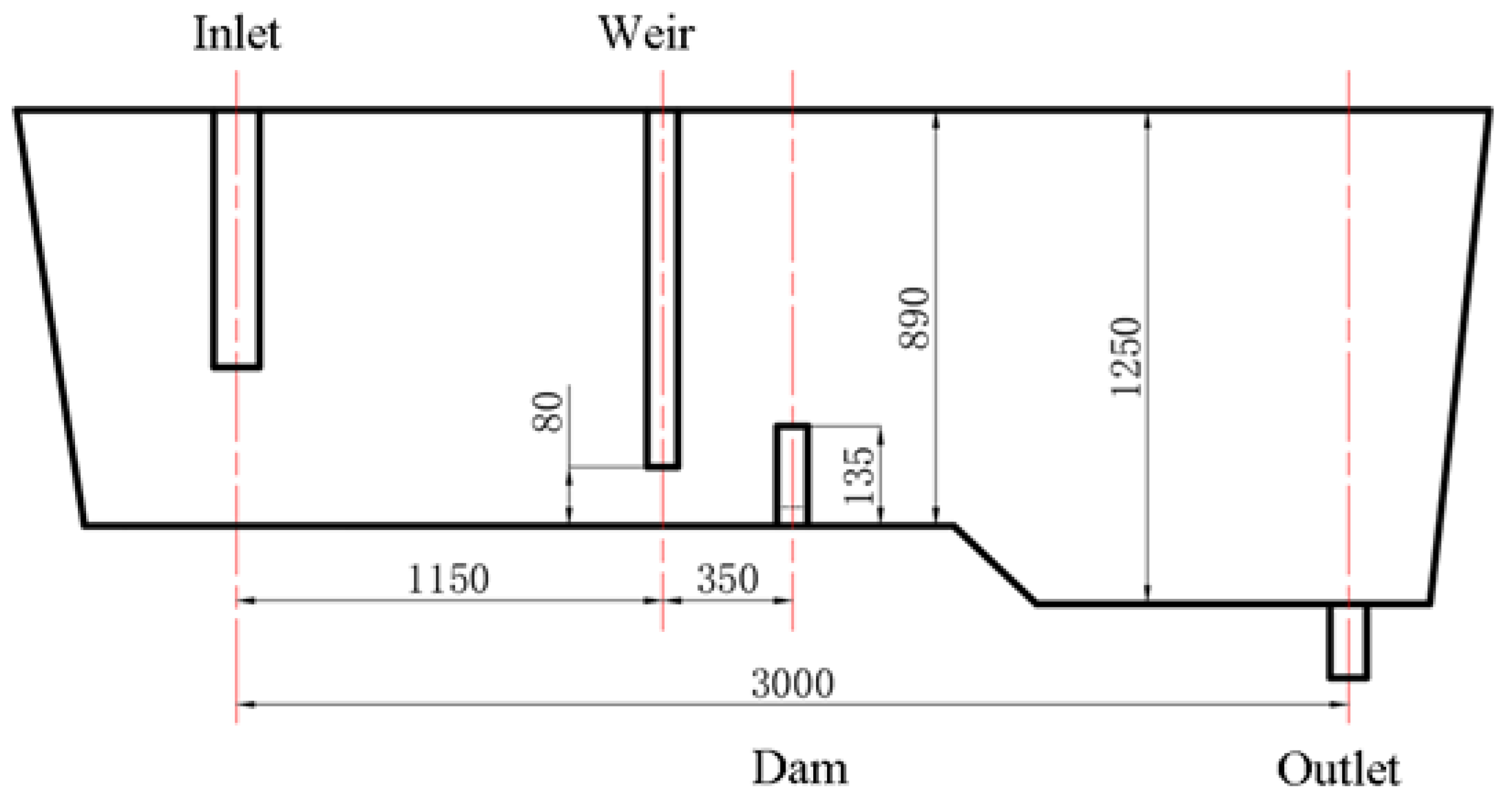
Taking the single-strand tundish of a certain steel plant as the research object, a weir and dam are used as the flow control device, and a slide gate is used to control the flow rate of molten steel under the outlet of the tundish. The size of the tundish is shown in Figure 1. This steel plant mainly produces 316L stainless steel, with a liquidus temperature of 1436 °C. The physical parameters of the molten steel in the numerical model were set to match those of 316L stainless steel products. The expression of physical property parameters is shown in Table 1, which is calculated based on actual production data using the material performance simulation software JMatPro 7.0. When producing 316L stainless steel, the superheat of the molten steel entering the mold should be controlled at 30 °C. Considering the heat loss in the tundish, the temperature of the molten steel entering the tundish is 1500 °C after each ladle change. Subsequently, due to the heat loss in the ladle, the temperature of the molten steel entering the tundish continuously decreases.

Figure 1.
Schematic of tundish for 316L production. (Unit: mm).

Table 1.
Parameter setting of simulation calculation process.
The flow of molten steel is complex and varied, accompanied by processes such as momentum transfer, heat transfer, species transfer, and interactions between inclusions and molten steel [30,31,32]. To simplify the simulation process, the following assumptions are made [33,34,35,36,37]:
- The molten steel in the tundish is regarded as an incompressible Newtonian fluid, ignoring the influence of slag and air on the flow field;
- Ignore the impact of liquid level rise and fall during the ladle change process;
- Neglect inclusions generated by slag rolling, the reoxidation of molten steel, erosion of refractory materials;
- The inclusions are all spherical and the interaction between inclusions is ignored;
- There is no inclusion removal to the walls.
2.2. Governing Equation
The conservation of mass, momentum, and energy equations are as follows:
where t is time, is the flow rate of the molten steel, and μ is the viscosity of the molten steel.
Using the Realizable k-ε model to solve the turbulent flow field inside the tundish, the momentum conservation equation is as follows:
where k is turbulent kinetic energy, m2/s2; is turbulent energy dissipation rate, m2/s3; is turbulent kinetic energy generated by the average velocity gradient, m2/s2; is turbulent kinetic energy caused by buoyancy, m2/s2; is Prandtl number corresponding to turbulent kinetic energy; and as the source term; C1, C2, C1ε, and C3 are all constants: C1 = 1.44, C2 = 1.93, = 1.0, and = 1.3. The calculation formula of is as follows:
The simulation of non-metallic inclusions in the tundish is implemented using the Lagrange Discrete Phase Model (DPM) to simulate the motion of non-metallic inclusion particles in the tundish. The inclusions are treated as discrete phase, and the transport equations of each inclusion are integrated to obtain the transport equation of the inclusions as follows:
where is the mass of the inclusion particles, is the velocity of the inclusion particles, is the density of the inclusion particles, includes virtual mass force, pressure gradient force, Saffman lift force and other forces acting on the inclusion particles [38,39,40,41,42], and is the particle relaxation time:
where μ is the molecular viscosity of the fluid, is the drag coefficient, and the drag law of spherical particles is used. Re is the relative Reynolds number:
2.3. Boundary Conditions
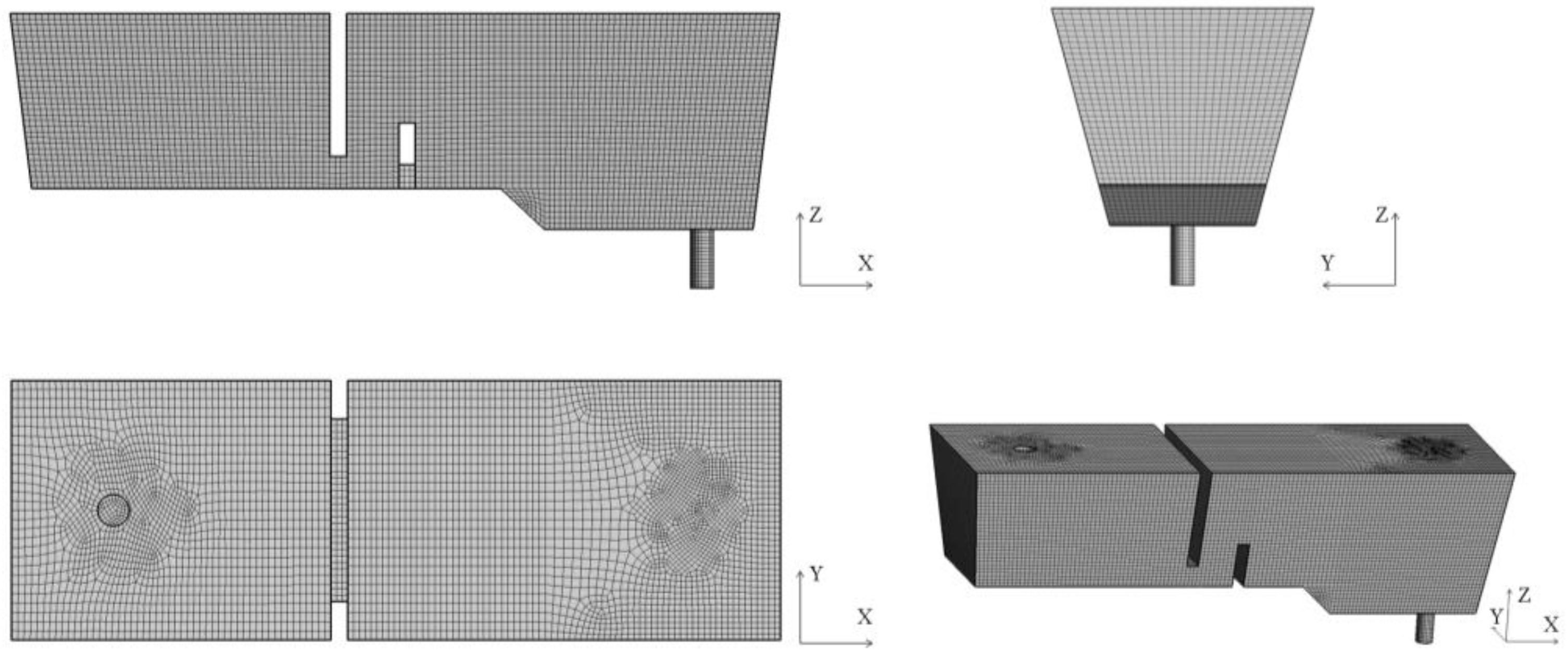
A three-dimensional geometric model with a similarity ratio of 1:1 between the model and the prototype was constructed based on the actual drawings and data. A hexahedral mesh was used for mesh division, as shown in Figure 2.

Figure 2.
Schematic diagram of the mesh for the tundish.
The solid walls of the tundish are all set as non-slip walls, and standard wall functions are used to treat them. The heat flux density of the front and rear walls is −15,000 W/m2, the left and right walls are −3800 W/m2, the steel–slag interface is −3200 W/m2, and the bottom wall is −1400 W/m2. The negative sign indicates that heat is lost outward from the tundish.
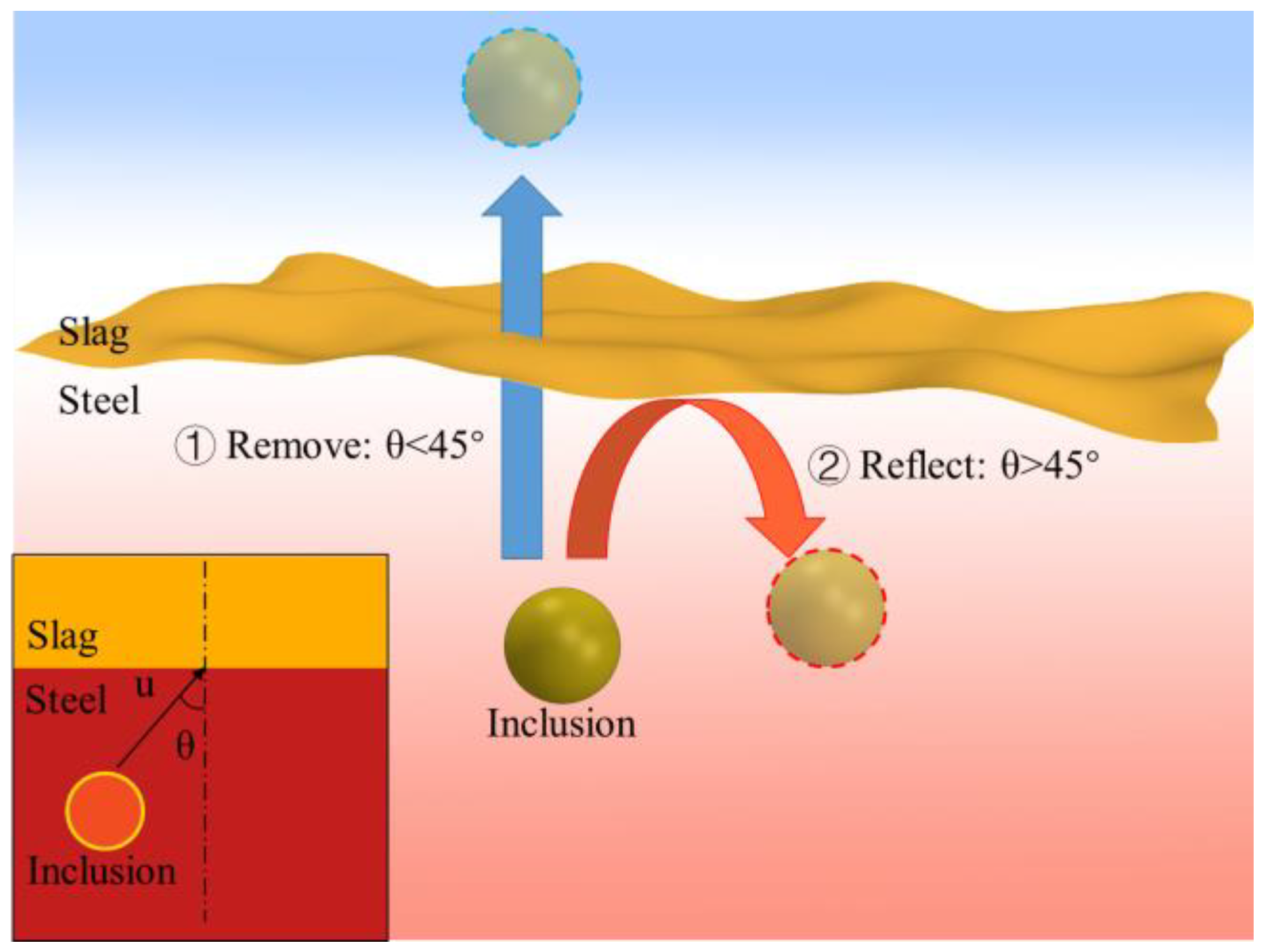
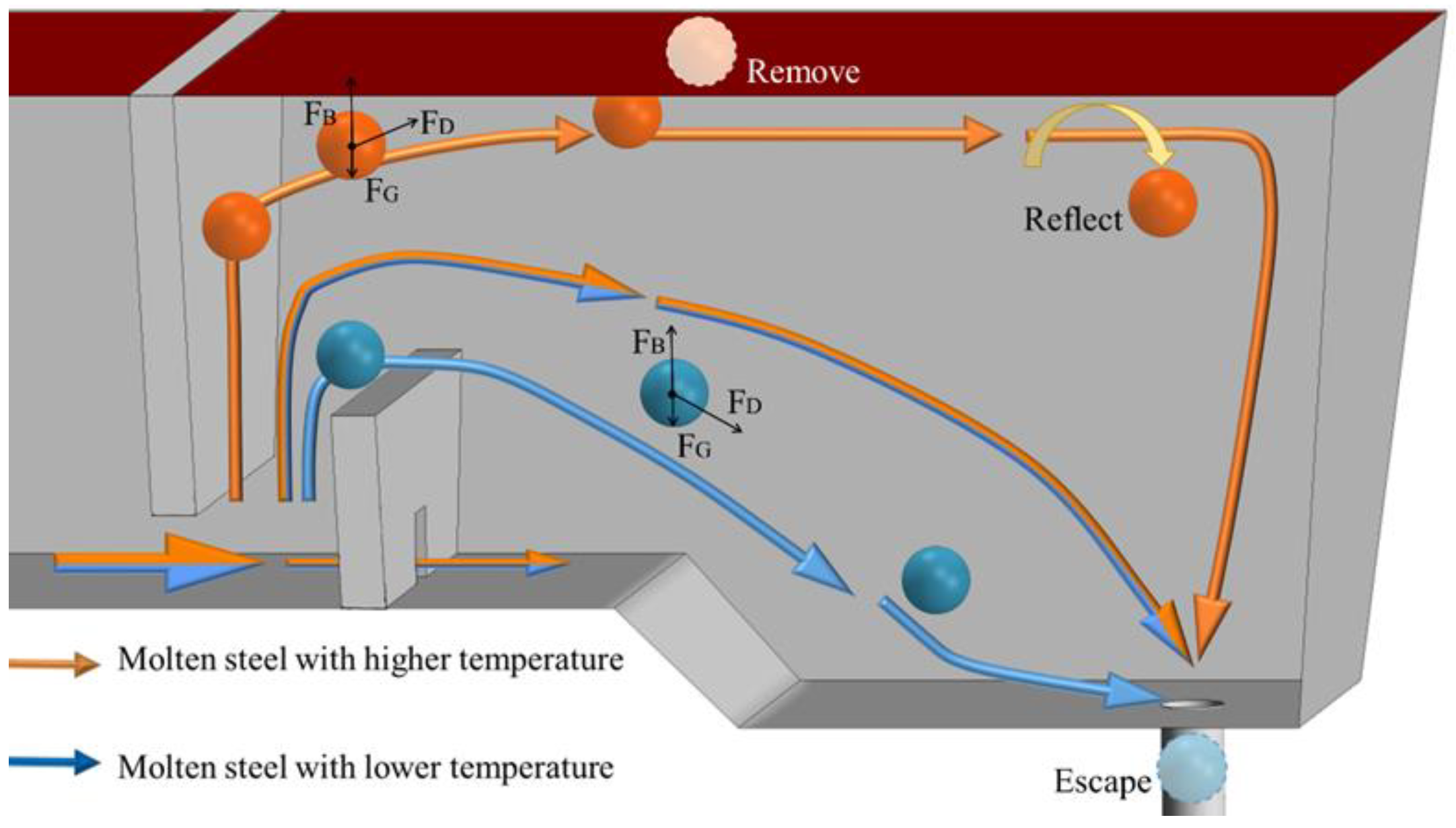
Inclusion particles are injected into the tundish together with the molten steel through the ladle shroud. When the inclusion particles reach the steel–slag interface, depending on the direction of movement, they may enter the liquid slag layer and be trapped and removed, or they may be brought back to the tundish by the molten steel. This study uses the angle between the velocity direction of the inclusion particles and the normal direction of the steel–slag interface as a criterion for removal. If the angle between the velocity and the normal direction is less than 45° when reaching the steel–slag interface, it can be removed. Otherwise, it will be reflected back into the tundish, as shown in Figure 3. When inclusions come into contact with other boundaries, they will be reflected.

Figure 3.
Schematic diagram of inclusion removal behavior.
3. Model Validation
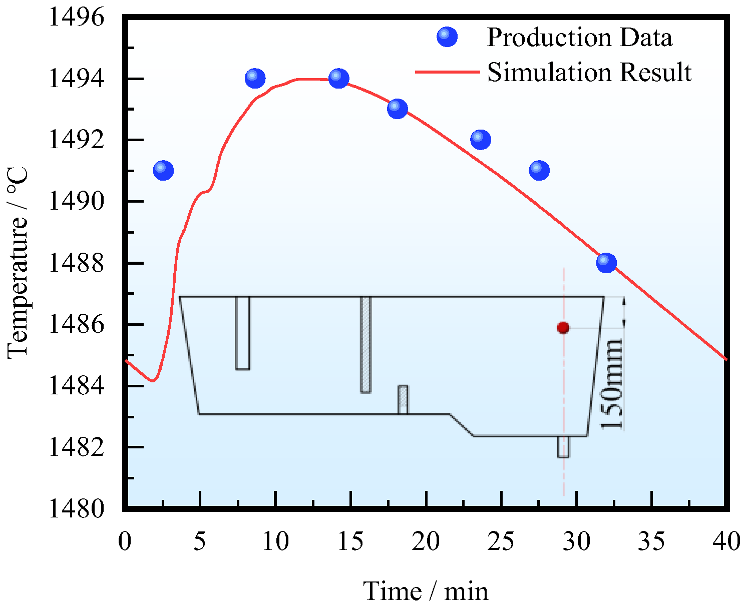
When producing 220 mm × 1860 mm stainless steel slab with a casting speed of 1.1 m/min, temperature measurement was carried out on the upper part of the tundish. In practice, a sensor is located above the submerged entry nozzle, 150 mm away from the steel–slag interface. A monitoring point is set at the same location in the numerical model.
The comparison between measurement data and simulation results is shown in Figure 4. The inlet temperature reduction rate (ITRR) used for simulation is 0.4 °C/min. The interval between two ladle changes is considered a casting period, with each period lasting 40 min. The 0 min mark on the X-axis indicates the start of casting molten steel in a ladle, the 40 min mark indicates the completion of casting the molten steel in the ladle, and then the next period begins. It can be found that, at the beginning of each casting period, the temperature at the monitoring point first decreases, and then slowly increases with the injection of high-temperature molten steel. The temperature reaches its maximum around the 10th minute, and then the temperature at the monitoring point decreases as the temperature of the fresh molten steel continues to decrease. The temperature change trend at the monitoring point is in good agreement with the fact.

Figure 4.
Comparison between simulation and measurement result.
4. Results and Discussion
4.1. Influence of Thermal Buoyancy on Flow Field
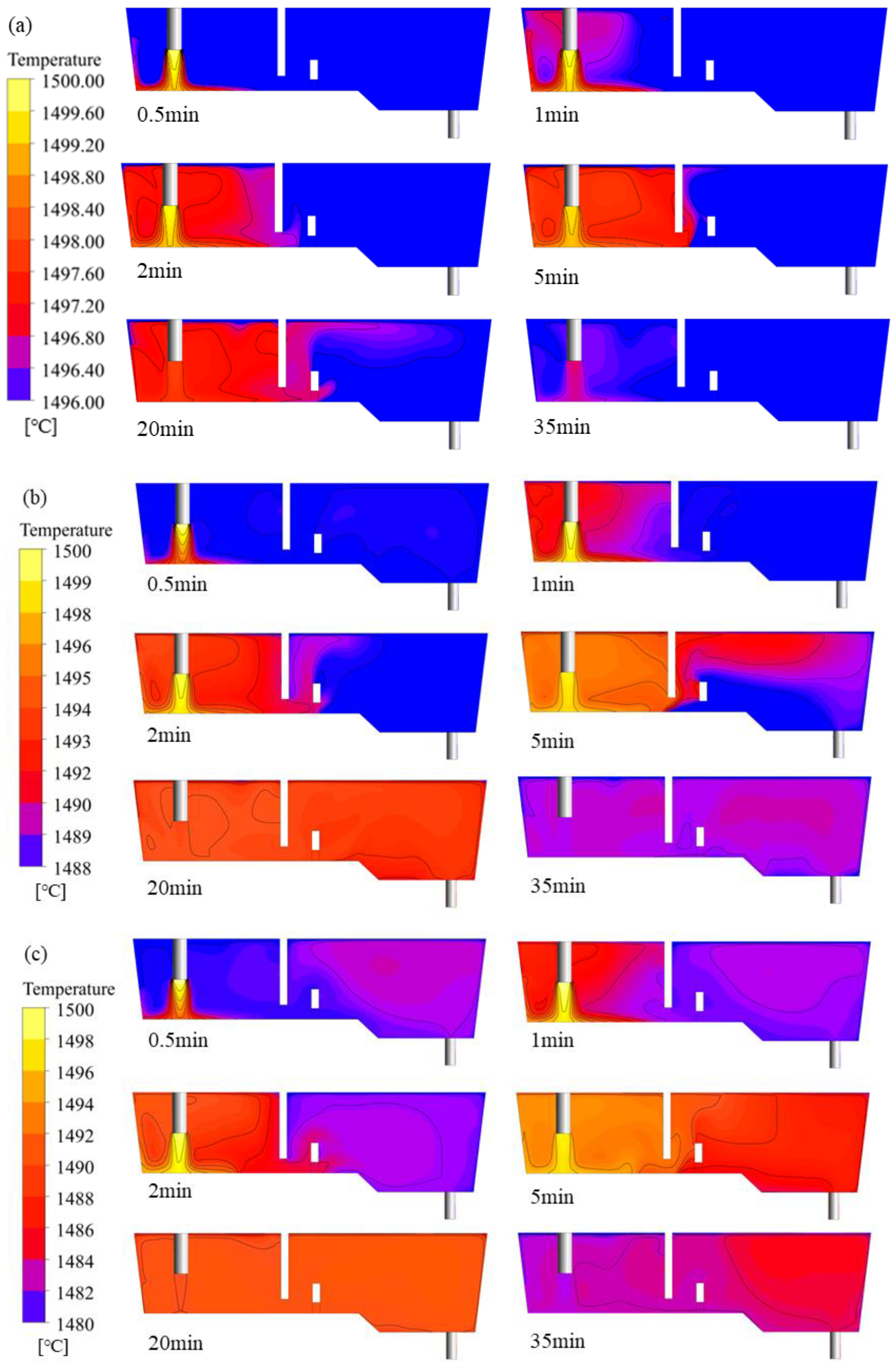
The insulation performance of the ladle will affect the ITRR, thereby changing the buoyancy of the molten steel and affecting the flow condition inside the tundish. The simulation results of the temperature distribution of molten steel in the tundish under different ITRRs are shown in Figure 5. When the ITRR is low, the temperature of the incoming molten steel is always higher than that of the molten steel in the tundish. After the ladle change is completed, the high-temperature molten steel is injected into the tundish from the ladle shroud, and, under the action of thermal buoyancy, it rises and exchanges heat with the surrounding low-temperature molten steel, causing the temperature near the ladle shroud to rise. After passing through the dam, a portion of the molten steel crosses over from above the dam, while another portion flows out through an opening at the bottom of the dam and then flows towards the outlet while floating upwards, forming a horizontal stream under the steel–slag surface. When the ITRR is high, at the beginning of the casting period, due to the larger temperature difference, the effect of thermal buoyancy is more significant, causing the temperature near the ladle shroud to rise faster. When flowing through the weir and dam area, the molten steel quickly rises behind the dam, and there is less molten steel passing through the bottom hole of the dam, resulting in a temporary low-temperature area behind the dam. As the temperature of the injected steel decreases, the temperature difference between the inlet and outlet continuously decreases, and the buoyancy of the steel becomes smaller and smaller. After passing through the dam, molten steel flows directly toward the outlet instead of rising to the steel–slag interface. When the temperature at the inlet is lower than that at the outlet, due to the higher density of the molten steel entering the tundish, it is more difficult for the molten steel to reach the steel–slag interface and it mainly flows at the bottom of the tundish.

Figure 5.
Temperature distribution inside the tundish with different ITRRs: (a) 0.1 °C/min; (b) 0.3 °C/min; (c) 0.5 °C/min.
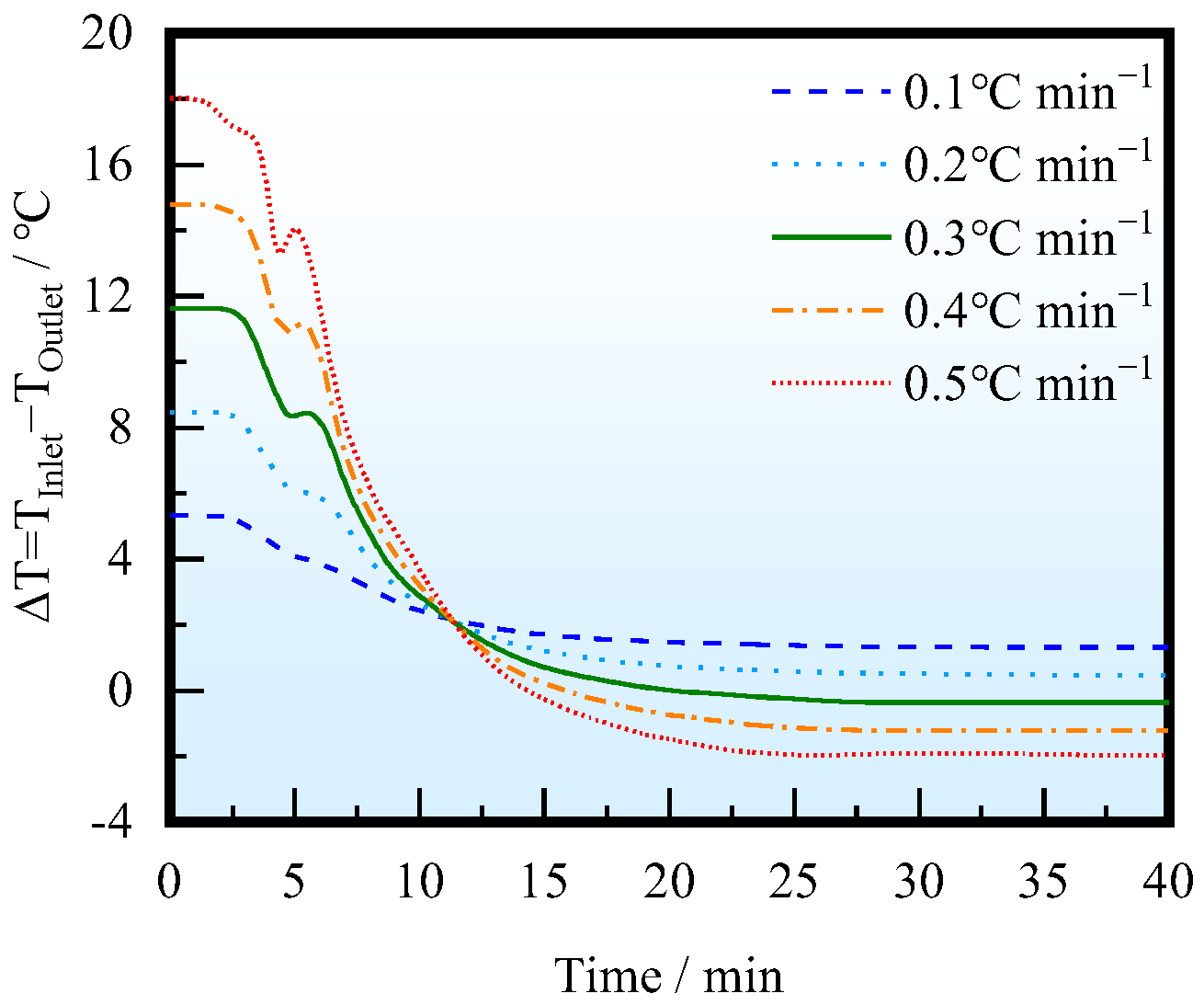
At a casting speed of 1.1 m/min, the flow characteristics were studied with different ITRRs: 0.5, 0.4, 0.3, 0.2, and 0.1 °C/min. Figure 6 shows the temperature difference curve between the inlet and outlet of the tundish. When the ITRR is high, that is, the insulation effect of the ladle is poor, the inlet temperature will be lower than the outlet temperature in the second half of the casting period, and the density of the molten steel entering the tundish is higher than that inside the tundish, which is not conducive to the formation of a horizontal stream on the top of the tundish and thus affects the movement and removal of inclusion particles.

Figure 6.
Variation in the temperature difference between the inlet and outlet with different ITRRs.
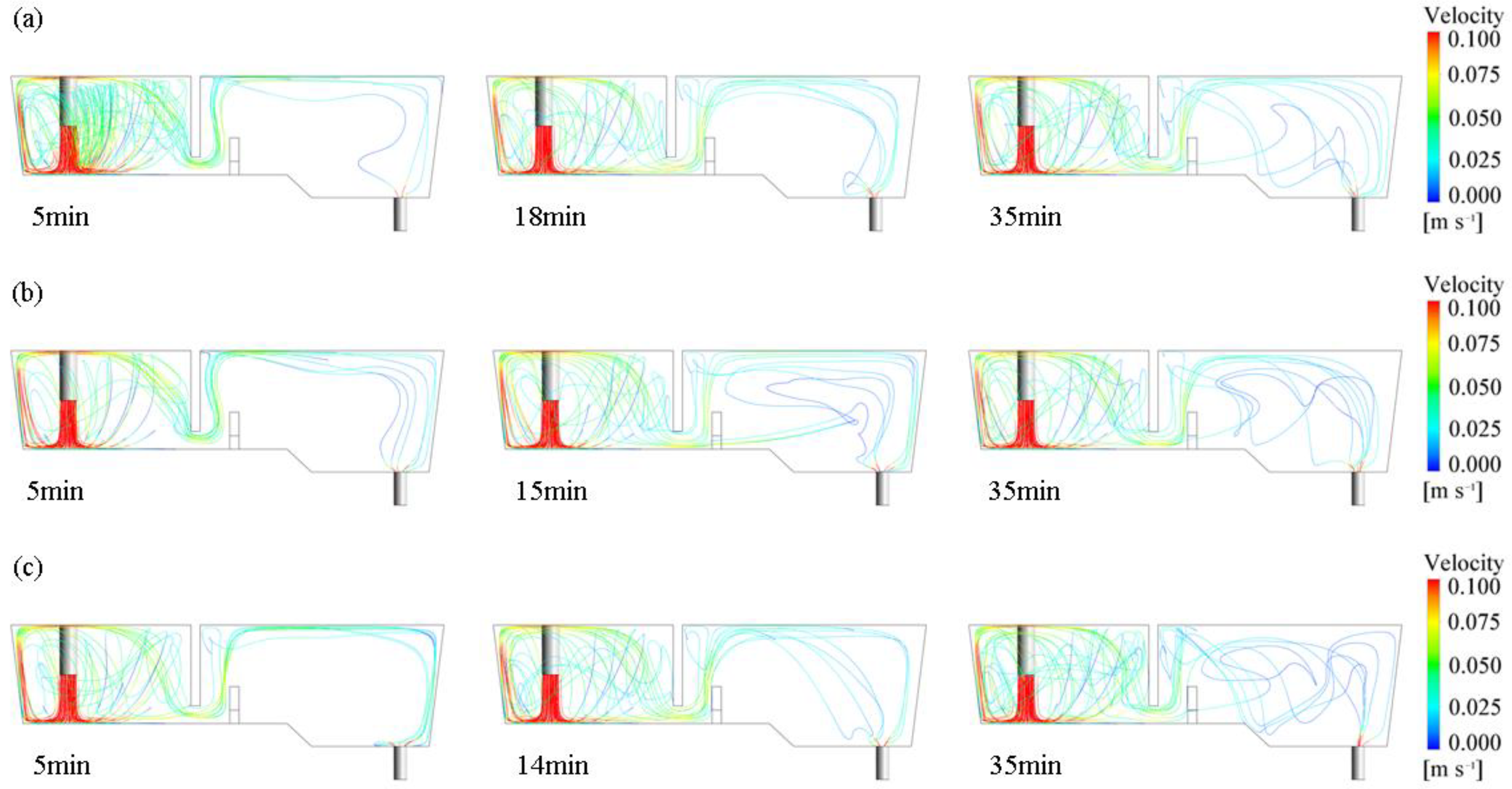
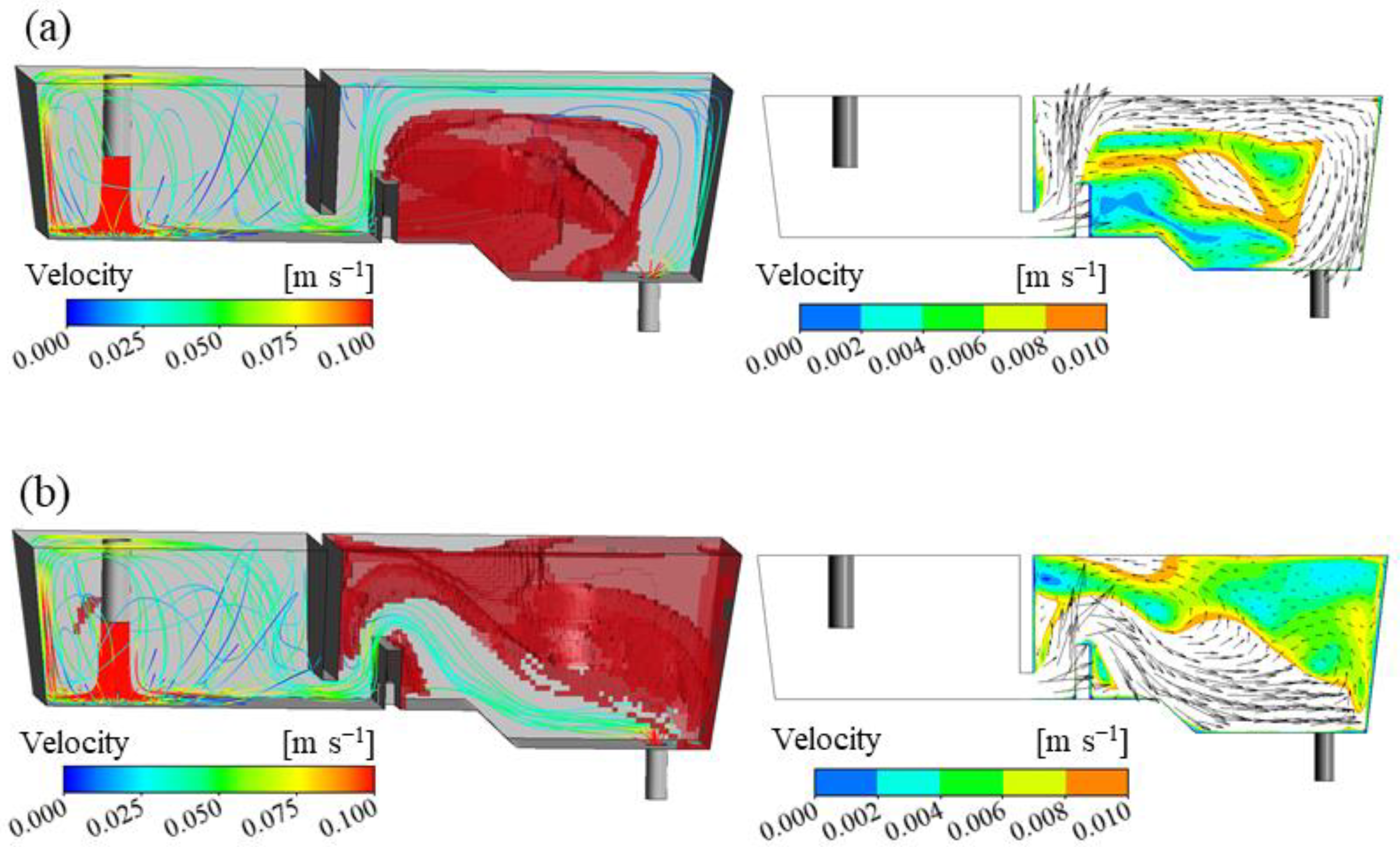
The changes in streamlining inside the tundish under different ITRRs are shown in Figure 7. The molten steel is injected into the tundish through the ladle shroud and impacts the bottom of the tundish. It then turns around in the weir and dam area and then a stream flows across the dam towards the steel–slag interface and forms a horizontal stream, which is conducive to driving inclusions to quickly float up; the other stream passes through the bottom hole of the dam and flows towards the outlet, eventually converging and flowing out at the outlet. When the inlet temperature is higher, the molten steel flows near the steel–slag interface due to the lifting effect of thermal buoyancy after crossing the dam. When the inlet temperature is lower, the molten steel sinks after crossing the dam, and the upper part of the tundish cannot maintain a stable horizontal stream. If the ITRR is low (0.1, 0.2 °C/min), the upstream temperature in the tundish will always be higher than the downstream, and the horizontal stream behind the dam can be maintained throughout the entire casting period. If the ITRR is large (0.3–0.5 °C/min), the horizontal stream can only be maintained in the first half of the casting period, and, the larger the ITRR, the shorter the duration of the horizontal stream. When the ITRR is 0.3, 0.4, and 0.5 °C/min, the duration of the horizontal stream is 18, 15, and 14 min, respectively, which is nearly consistent with the time when the inlet temperature is higher than the outlet temperature.

Figure 7.
Distribution of streamline inside the tundish with different ITRRs: (a) 0.3 °C/min; (b) 0.4 °C/min; (c) 0.5 °C/min.
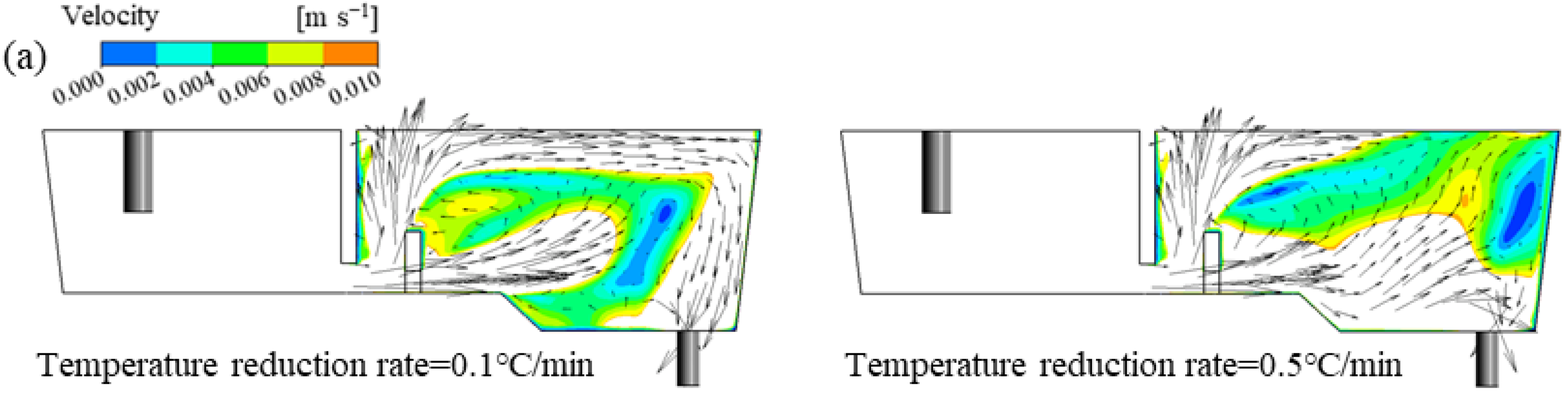
Dead zone refers to the area where the flow of molten steel in the tundish stagnates. The distribution of the dead zone is determined by the flow velocity of molten steel and the area where the flow velocity is less than 30% of the average flow velocity is identified as a dead zone. According to whether the temperature of the incoming molten steel is higher or lower, the flow pattern in the tundish can be divided into two types. The visual distribution of the dead zone is shown in Figure 8. When the temperature of the incoming steel is higher, under the action of thermal buoyancy, the steel will form a stable horizontal stream at the steel–slag interface behind the weir. The steel will flow near the steel–slag interface, impact the wall near the outlet, and then turn towards the outlet. In this case, the dead zone is distributed between the dam and the outlet. When the temperature of the incoming steel is lower, the steel flows at the bottom of the tundish, and the dead zone is distributed in the area behind the weir and above the outlet. Therefore, when the temperature of the incoming molten steel is higher, it is more conducive for the molten steel to reach the steel–slag interface, thereby facilitating the removal of inclusion particles and improving the cleanliness. Within one period, when the ITRR is 0.5, 0.4, 0.3, 0.2, and 0.1 °C/min, the average dead zone volume fraction is 21.7%, 22.9%, 24.2%, 24.7%, and 27.9%, respectively. Therefore, when the ITRR is high, the dead zone volume fraction is also high, which is not conducive to the removal of inclusion particles.

Figure 8.
Dead zone positions with different temperature distributions: (a) the temperature of the incoming molten steel is higher; (b) the temperature of the incoming molten steel is lower.
4.2. Influence of Thermal Buoyancy on Inclusion Removal
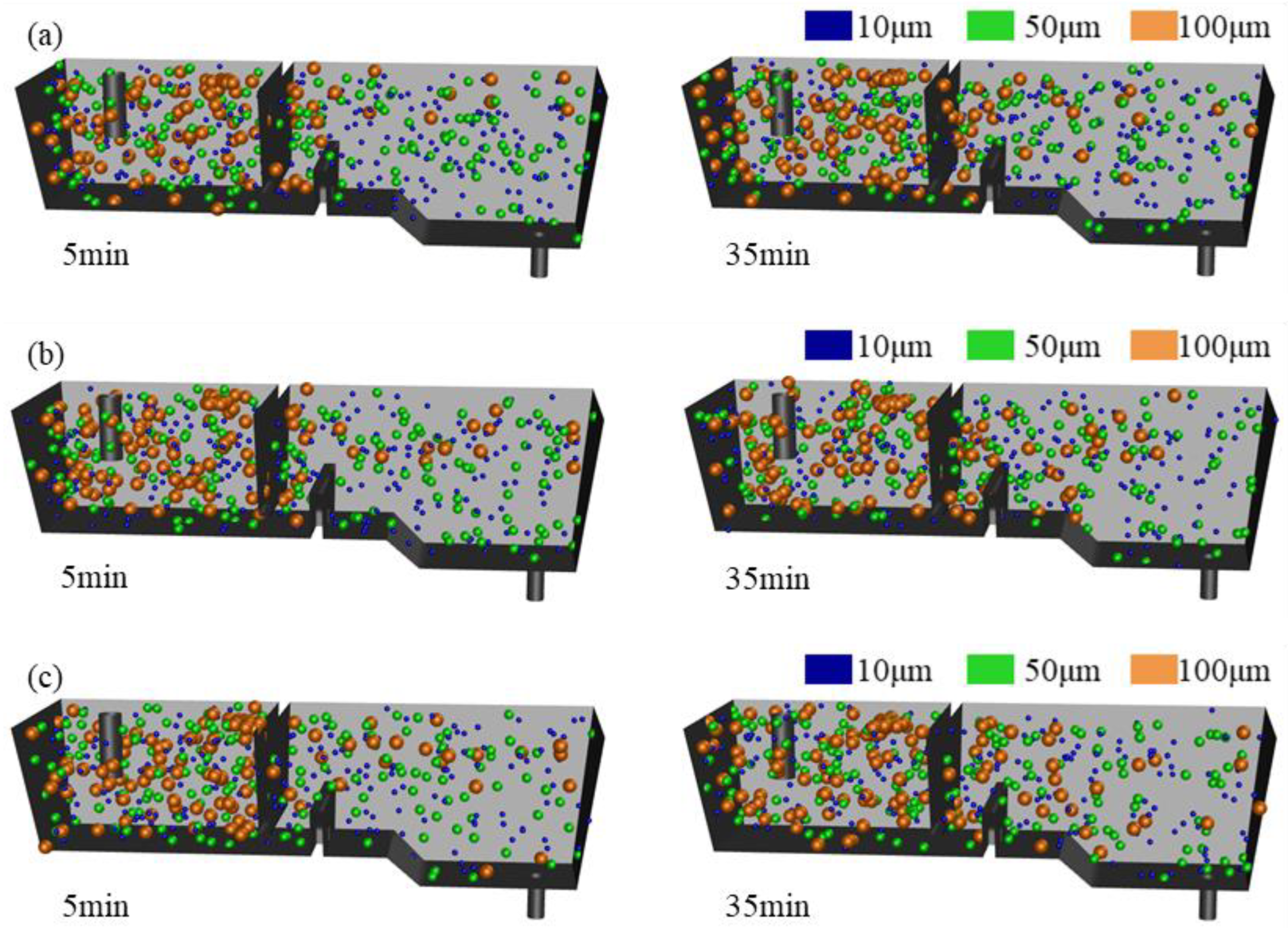
In order to compare the effect of thermal buoyancy on the removal of inclusions, the motion of inclusion particles with diameters of 10, 50, and 100 μm was simulated under different operating conditions. Figure 9 shows the distribution of inclusions in the tundish. It can be seen that large inclusions have a shorter residence time, mostly concentrated in the entrance area, while small inclusions distributed at various positions in the tundish. Large inclusions are more likely to float up, and most of them are removed before reaching the outlet. Small inclusions are easily dragged deep into the tundish by the molten steel and enter the mold together with the molten steel. In the first half of the casting period, the horizontal stream exists behind the weir with various conditions, and inclusion particles are more likely to float up, mostly distributed in the upper part of the tundish. In the second half of the casting period, if the ITRR is high, the molten steel is difficult to float up and flows at the bottom of the tundish, which will carry inclusion particles to the lower part of the tundish.

Figure 9.
Motion of inclusions in the tundish with different ITRRs: (a) 0.1 °C/min; (b) 0.3 °C/min; (c) 0.5 °C/min.
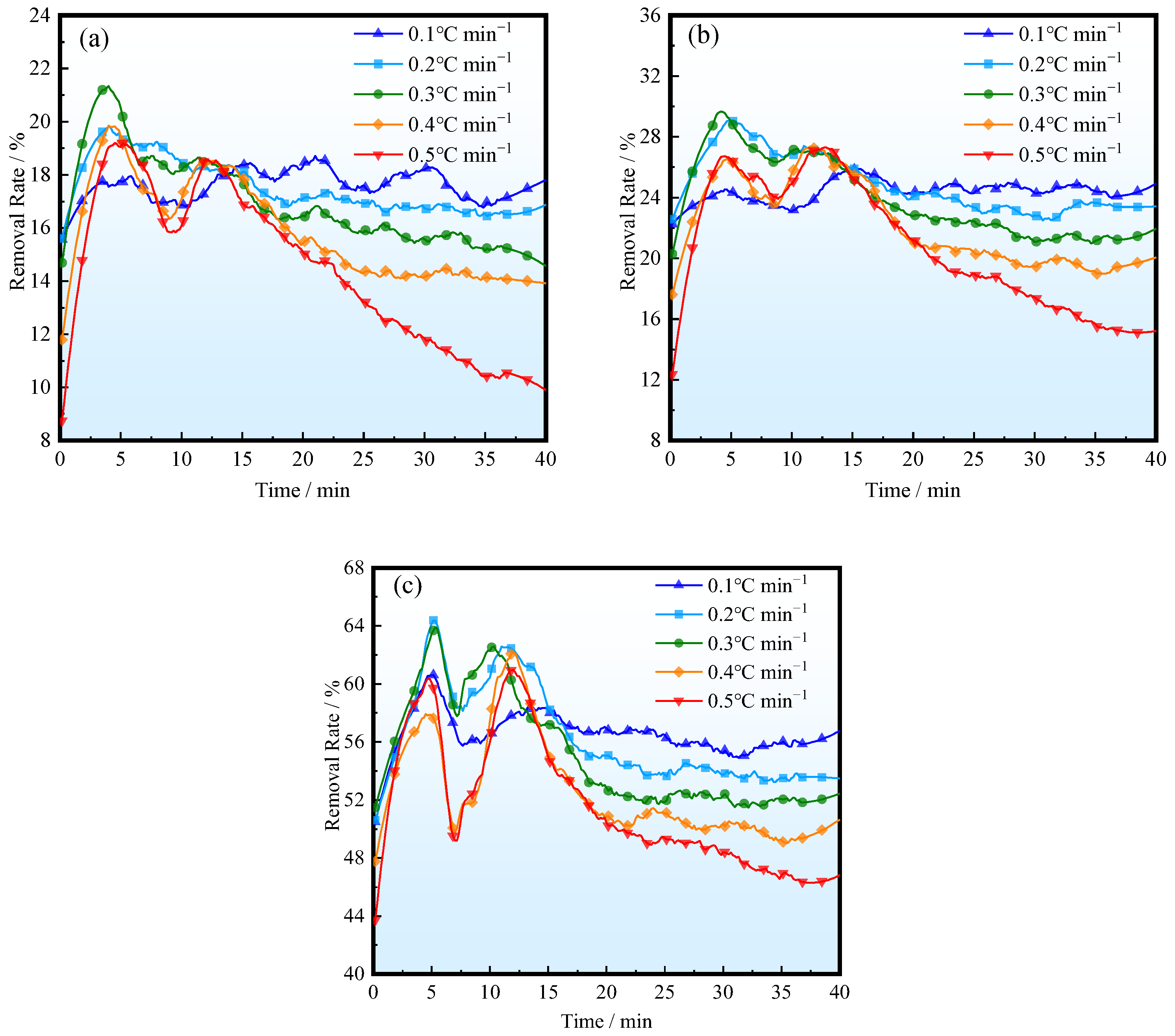
Figure 10 shows the changes in removal rates of inclusions of different sizes at different ITRRs. It can be seen that, when the ITRR is low, the removal rate of inclusions does not change much throughout the entire casting period. When the ITRR is high, the removal of inclusions first increases and then decreases. This is because, at the beginning, the temperature of the molten steel entering the tundish is higher, and the molten steel rises upward under the influence of thermal buoyancy, which is beneficial for the removal of inclusions. As the inlet temperature decreases and the temperature difference decreases, the effect of thermal buoyancy becomes less significant. When the temperature of the molten steel entering the tundish is lower, the upward movement of the flow slows down, resulting in a decrease in the removal rate. The removal rate of large-sized inclusions is higher, and the removal rate of inclusions will be higher when the ITRR is lower. When the ITRR is 0.1 °C/min, the average removal rates of inclusions of 10, 50, and 100 μm are 20.9%, 28.7%, and 59.6%, respectively, and, when the ITRR is 0.5 °C/min, the removal rates are 17.9%, 24.8%, and 55.2%, respectively.

Figure 10.
Removal rates of various inclusions: (a) d = 10 μm; (b) d = 50 μm; (c) d = 100 μm.
4.3. The Influence of Casting Speed on the Removal Rate of Inclusions
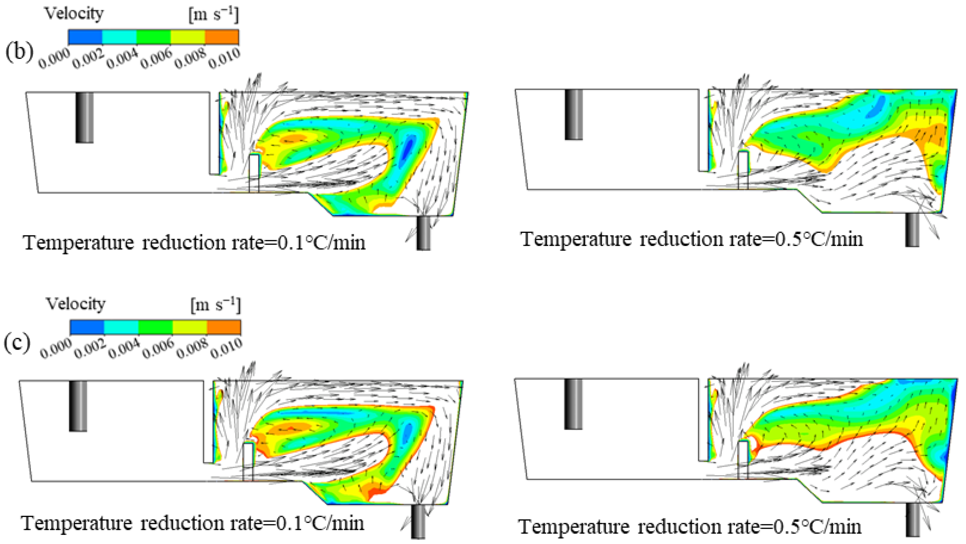
The effects of thermal buoyancy on the flow field and inclusion movement inside the tundish at different casting speeds were compared. The distribution of dead zones in the second half of the casting period is shown in Figure 11. When the casting speed is 1.1, 1.2, and 1.3 m/min, the average residence time of the molten steel is 422 s, 460 s, and 498 s, and the average flow velocity is 0.0275, 0.0297, and 0.0320 m/s. Therefore, the corresponding dead zone critical velocities are 0.0083, 0.0089, and 0.0096 m/s, respectively. At different casting speeds, the influence of thermal buoyancy on the distribution of dead zones is almost the same, and increasing the casting speed will reduce the volume of the dead zone. When the ITRR is high, increasing the casting speed will make it more difficult for inclusions to float up, and will accelerate the convective heat transfer of molten steel in the tundish.
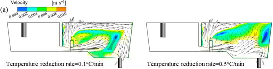

Figure 11.
Dead zone distribution under different casting velocities: (a) 1.1 m/min; (b) 1.2 m/min; (c) 1.3 m/min.
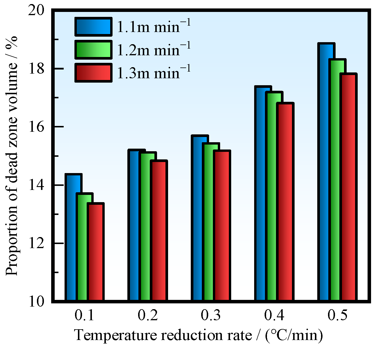
The change in casting speed will directly affect the velocity and temperature distribution inside the tundish, thereby affecting the inclusion removal rate. Figure 12 shows the average dead zone volume fraction at different ITRRs and casting speeds of 1.1, 1.2, and 1.3 m/min. The higher the ITRR, the higher the average dead zone volume fraction. The higher the casting speed, the smaller the volume fraction of the dead zone, and also promotes convective heat transfer in the tundish, reducing the temperature difference between the inlet and outlet faster.

Figure 12.
Average volume fraction of dead zone.
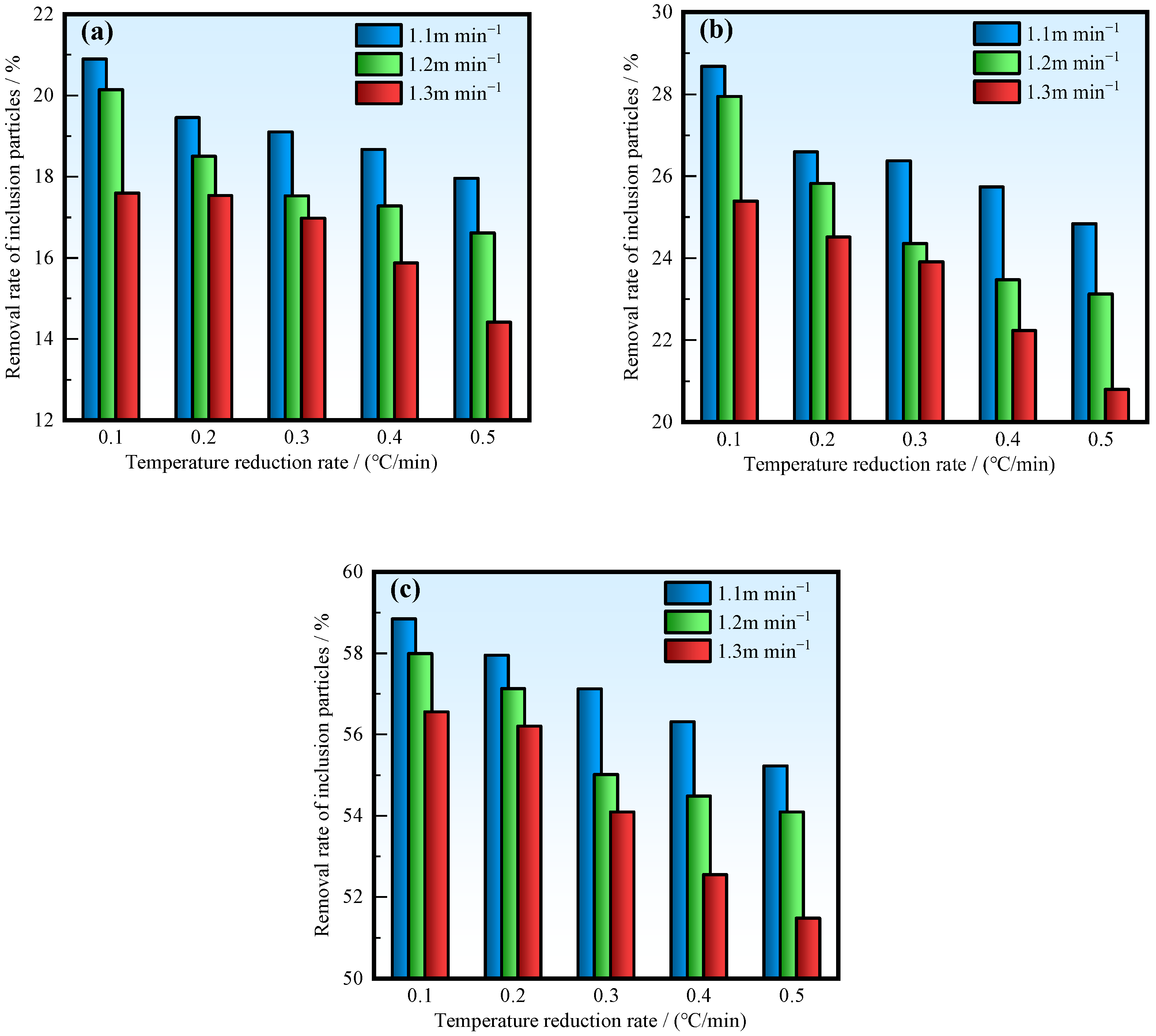
The variation of the average removal rate of inclusion particles is shown in Figure 13. It can be seen that the higher the casting speed, the lower the removal rate of inclusions. At an ITRR of 0.5 °C/min, the removal rates of three types of inclusion particles decreased by 2.8%, 3.5%, and 3.8% at a casting speed of 1.3 m/min compared to 1.1 m/min. This is because, when the casting speed is high, the residence time of inclusions is short, making it difficult to float up and remove. As a result, the proportion of inclusions entering the mold with the molten steel increases. The higher the casting speed, the faster the molten steel is mixed, and the faster the temperature difference between the inlet and outlet decreases. At an ITRR of 0.5 °C/min and casting speeds of 1.1, 1.2, and 1.3 m/min, the time required for the temperature difference between the inlet and outlet to reach 0 is 14.3, 13.4, and 12.7 min, respectively. Therefore, a higher casting speed will reduce the duration of horizontal stream existence and the removal rate of inclusion particles.

Figure 13.
Average removal rates of various inclusions: (a) d = 10 μm; (b) d = 50 μm; (c) d = 100 μm.
4.4. Factors Affecting the Movement of Inclusions
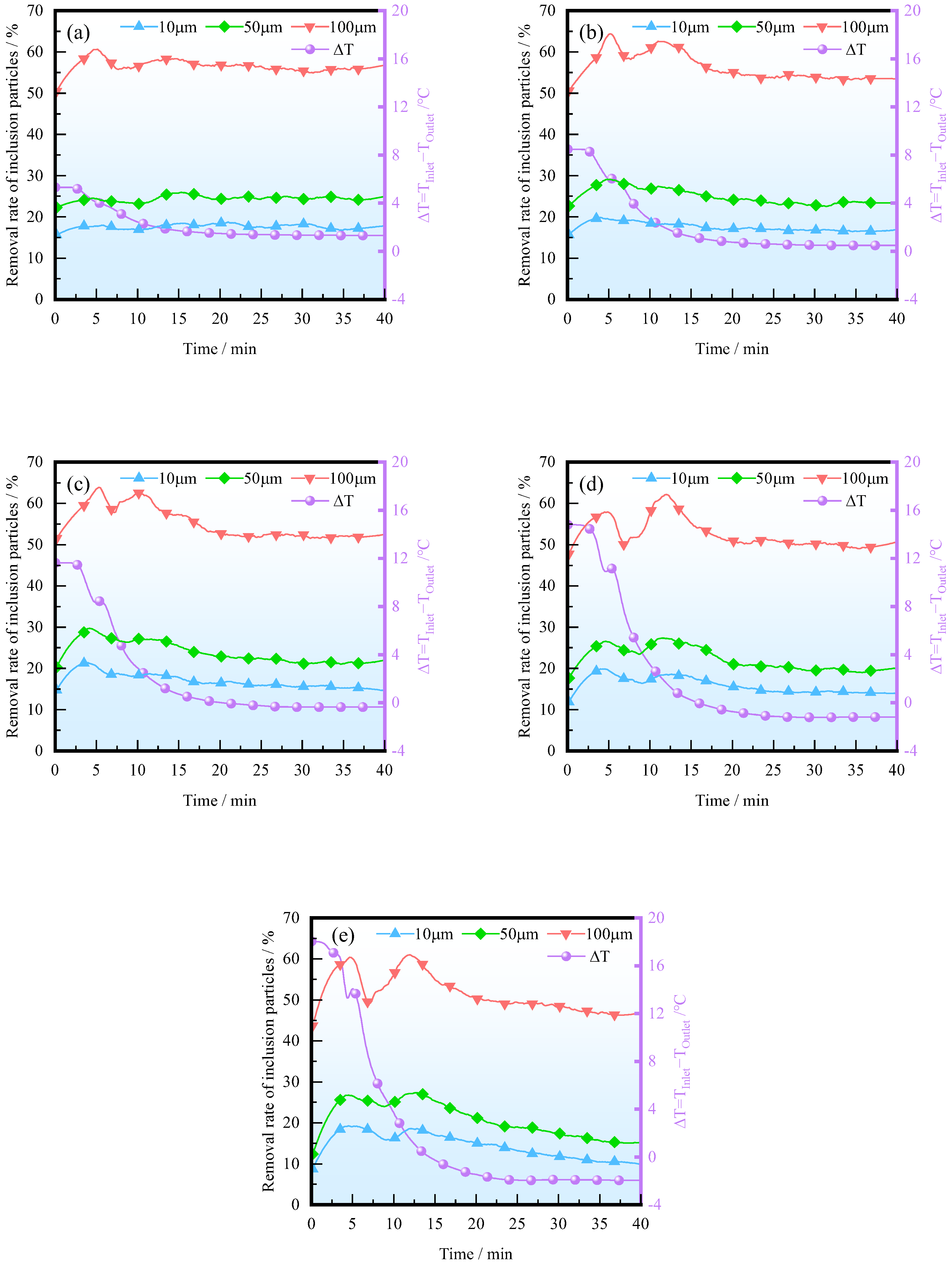
The variations in the temperature difference between the inlet and outlet of the tundish and the removal rate of inclusion particles during a casting period at different ITRRs are shown in Figure 14. It can be seen that in, the early stage of the casting period, due to the increase in temperature difference, the removal rate has increased. The larger the ITRR, the greater the temperature difference in the early stage of casting, and the more significant the promoting effect of thermal buoyancy on the upward floating of inclusions. As the temperature difference gradually stabilizes, the removal rate of inclusions also gradually decreases and tends to stabilize.

Figure 14.
The variation in removal rates with different ITRRs: (a) 0.1 °C/min; (b) 0.2 °C/min; (c) 0.3 °C/min; (d) 0.4 °C/min; (e) 0.5 °C/min.
When inclusions move in molten steel, the main flow direction of the steel and the forces acting on the inclusion particles are shown in Figure 15. The forces acting on the inclusions mainly include drag, buoyancy, and gravity. Thermal buoyancy directly affects the velocity and direction of molten steel flow inside the tundish and affects the movement of inclusion particles through drag. The drag force hinders the relative motion between inclusion particles and molten steel. When the combined force of drag, buoyancy, and gravity is upward, the inclusions gain upward acceleration. Therefore, in the first half of the casting period, the thermal buoyancy promotes the molten steel entering the tundish to float up, forming a horizontal stream after the weir, which is conducive to improving the removal rate of inclusions. In the second half of the casting period, if the ITRR is high and the temperature of the molten steel entering the tundish is low, the upward flow will be suppressed, and it will be difficult for the molten steel to reach the steel–slag interface after crossing the dam, resulting in a decrease in the removal rate of inclusion particles.

Figure 15.
Schematic diagram of forces on inclusion particles.
The expressions for drag, buoyancy, and gravity are as follows:
The larger the diameter of the inclusion, the higher the particle Reynolds number Re. For small-sized inclusions, the drag coefficient remains in the Stokes Zone, while, for large-sized inclusions, it may enter the Allen Zone. From Equations (13) and (14), it can be seen that, when the velocity of the molten steel changes, the acceleration of small-sized inclusion particles changes significantly. Therefore, the movement of small-sized inclusions is greatly affected by drag force. When the promoting effect of thermal buoyancy on the upward movement of the molten steel disappears, small-sized inclusions are more difficult to float up. Due to the lower upward velocity, they may also be brought back to the deep part of the tundish by the molten steel after reaching the steel–slag interface. Therefore, attention should be paid to improving the insulation performance of the ladle and the tundish and making good use of thermal buoyancy to improve the cleanliness of molten steel.
5. Conclusions
The flow and heat transfer of molten steel in a single-strand tundish, as well as the motion of inclusion particles, are investigated through numerical simulation. The influence mechanism of thermal buoyancy on the removal rate of inclusions is analyzed, leading to the following main conclusions:
- (1)
- The molten steel entering the tundish is affected by thermal buoyancy due to the temperature gradient. When the inlet temperature is high, the molten steel floats up under the action of thermal buoyancy and can form a horizontal stream behind the weir. Conversely, when the inlet temperature is low, it becomes challenging for the molten steel to reach the steel–slag interface, resulting in an inability to maintain a horizontal stream behind the dam.
- (2)
- At elevated inlet temperatures, there is an increase in inclusion removal rates. However, as inlet temperature decreases—specifically, when lower than outlet temperature—the rate of inclusion removal diminishes.
- (3)
- The larger the diameter of inclusions and the smaller the ITRR, the higher the removal rate of inclusions. When the ITRR is 0.1 °C/min, the average removal rates of inclusions of 10, 50, and 100 μm are 20.9%, 28.7%, and 59.6%, respectively; when the ITRR is 0.5 °C/min, the removal rates are 17.9%, 24.8%, and 55.2%, respectively.
- (4)
- Increasing the casting speed will shorten the duration of the horizontal stream behind the weir, making it easier for inclusions to be carried into the mold by the molten steel in the lower part of the tundish. Therefore, the casting speed and insulation performance of the ladle and tundish should be taken into account when formulating production processes so as to improve the cleanliness of the molten steel in the tundish.
Author Contributions
Conceptualization, D.W.; methodology, T.Q.; software, T.Q.; validation, Z.Z., X.L. and X.Z.; formal analysis, Z.Z. and X.L.; investigation, Z.Z. and L.F.; resources, T.Q. and D.W.; data curation, Z.Z. and X.Z.; writing—original draft, Z.Z.; writing—review and editing, T.Q. and L.F.; supervision, D.W.; project administration, D.W.; funding acquisition, Z.Z., T.Q., D.W., X.L. and L.F. All authors have read and agreed to the published version of the manuscript.
Funding
This work was supported by the National Natural Science Foundation of China (Grant Nos. 52174321, 52404349, 52274339, 52204348), the Postgraduate Research & Practice Innovation Program of Jiangsu Province (KYCX24_3310), Natural Science Foundation of Jiangsu Province (No. BK20240804), China Postdoctoral Science Foundation (No. 2024M762290), and Jiangsu Funding Program for Excellent Postdoctoral Talent (No. 2024ZB534).
Data Availability Statement
The original contributions presented in this study are included in the article. Further inquiries can be directed to the corresponding authors.
Conflicts of Interest
The authors declare no conflicts of interest.
References
- Sahai, Y. Tundish technology for casting clean steel: A review. Met. Mater. Trans. B 2016, 47, 2095–2106. [Google Scholar] [CrossRef]
- Dipak, M. Review, analysis, and modeling of continuous casting tundish systems. Steel Res. Int. 2019, 90, 1800279. [Google Scholar]
- Wang, Z.; Yang, Z.; Wang, X.; Yue, Q.; Xia, Z.; Xiao, H. Residence time distribution (RTD) applications in continuous casting tundish: A review and new perspectives. Metals 2022, 12, 1366. [Google Scholar] [CrossRef]
- Ma, W.-J.; Bao, Y.-P.; Zhao, L.-H.; Wang, M. Control of the precipitation of TiN inclusions in gear steels. Int. J. Miner. Met. Mater. 2014, 21, 234–239. [Google Scholar] [CrossRef]
- Bai, X.-F.; Sun, Y.-H.; Chen, R.-M.; Zhang, Y.-M.; Cai, Y.-F. Formation and thermodynamics of CaS-bearing inclusions during Ca treatment in oil casting steels. Int. J. Miner. Met. Mater. 2019, 26, 573–587. [Google Scholar] [CrossRef]
- Mishra, S.K.; Jha, P.K.; Sharma, S.C.; Ajmani, S.K. Numerical investigation of the effect of transitory strand opening on mixing in a multistrand tundish. Int. J. Miner. Met. Mater. 2011, 18, 535–542. [Google Scholar] [CrossRef]
- Sarkar, S.; Sambasivam, R.; Ajmani, S.K.; Denys, M.B. Numerical analysis of unsteady hydrodynamics and thermal transport in five-strand asymmetric tundish. Ironmak. Steelmak. 2012, 39, 540–549. [Google Scholar] [CrossRef]
- Wang, J.; Liu, Z.; Chen, W.; Chen, H.; Zhang, L. Numerical simulation on the multiphase flow and reoxidation of the molten steel in a two-strand tundish during ladle change. Int. J. Miner. Met. Mater. 2024, 31, 1540–1553. [Google Scholar] [CrossRef]
- Zhang, H.; Luo, R.; Fang, Q.; Ni, H.; Song, X. Numerical simulation of transient multiphase flow in a five-strand bloom tundish during ladle change. Metals 2018, 8, 146. [Google Scholar] [CrossRef]
- Quan, Q.; Zhang, Z.-X.; Qu, T.-P.; Li, X.-L.; Tian, J.; Wang, D.-Y. Physical and numerical investigation on fluid flow and inclusion removal behavior in a single-strand tundish. J. Iron Steel Res. Int. 2023, 30, 1182–1198. [Google Scholar] [CrossRef]
- Zhang, J.-S.; Qin, B.-M.; Liu, Y.-H.; Li, Q.-H.; Zuo, X.-T.; Wang, C.; Yang, S.-F.; Liu, Q. Multiphase flow inside a four-strand continuous casting tundish using three types of ladle shrouds. J. Iron Steel Res. Int. 2023, 30, 1171–1181. [Google Scholar] [CrossRef]
- Huitron, R.M.P.; Lopez, P.E.R.; Vuorinen, E.; Jalali, P.N.; Kärkkäinen, M. Identification of cracking issues and process improvements through plant monitoring and numerical modelling of secondary cooling during continuous casting of HSLA steels: Casting and solidification. ISIJ Int. 2021, 61, 834. [Google Scholar] [CrossRef]
- Sheng, D.-Y.; Jönsson, P.G. Effect of thermal buoyancy on fluid flow and residence-time distribution in a single-strand tundish. Materials 2021, 14, 1906. [Google Scholar] [CrossRef] [PubMed]
- Xie, Q.; Ni, P.; Ersson, M.; Jönsson, P.G.; Li, Y. Numerical simulations on dynamic behavior of multiphase flow and heat transfer in a round mold with a swirling flow tundish design. Met. Mater. Trans. B 2022, 53, 3197–3214. [Google Scholar] [CrossRef]
- Fang, Q.; Zhang, H.; Luo, R.; Liu, C.; Wang, Y.; Ni, H. Optimization of flow, heat transfer and inclusion removal behaviors in an odd multistrand bloom casting tundish. J. Mater. Res. Technol. 2020, 9, 347–363. [Google Scholar] [CrossRef]
- Yang, B.; Lei, H.; Bi, Q.; Jiang, J.; Zhang, H.; Zhao, Y.; Zhou, J. Fluid flow and heat transfer in a tundish with channel type induction heating. Steel Res. Int. 2018, 89, 1800173. [Google Scholar] [CrossRef]
- Dou, W.; Yang, Z.; Wang, Z.; Yue, Q. Molten steel flow, heat transfer and inclusion distribution in a single-strand continuous casting tundish with induction heating. Metals 2021, 11, 1536. [Google Scholar] [CrossRef]
- Zhu, M.; Peng, S.; Jiang, K.; Luo, J.; Zhong, Y.; Tang, P. Fluid flow and heat transfer behaviors under non-isothermal conditions in a four-strand tundish. Metals 2022, 12, 840. [Google Scholar] [CrossRef]
- Gonzalez, H.; Ramos-Banderas, J.A.; Torres-Alonso, E.; Solorio-Diaz, G.; Hernández-Bocanegra, C.A. Multiphase modeling of fluid dynamic in ladle steel operations under non-isothermal conditions. J. Iron Steel Res. Int. 2017, 24, 888–900. [Google Scholar] [CrossRef]
- Chattopadhyay, K.; Isac, M.; Guthrie, R.I.L. Applications of computational fluid dynamics (CFD) in iron-and steelmaking: Part 2. Ironmak. Steelmak. 2010, 37, 562. [Google Scholar] [CrossRef]
- Fang, Q.; Zhao, P.; Zhang, H.; Zhou, W.-H.; Yu, G.; Wang, J.-H.; Ni, H.-W. Formation of free-surface vortex and vortex suppression by rotating stopper-rod at end of tundish casting. J. Iron Steel Res. Int. 2024, 31, 1104–1116. [Google Scholar] [CrossRef]
- Ruan, Y.W.; Yao, Y.; Shen, S.Y.; Wang, B.; Zhang, J.Y.; Huang, J.K. Physical and mathematical simulation of surface-free vortex formation and vortex prevention design during the end of casting in tundish. Steel Res. Int. 2020, 91, 201900616. [Google Scholar] [CrossRef]
- Zhang, H.; Wang, J.; Fang, Q.; Wu, G.; Zhao, P.; Ni, H. Effect of top-swirling turbulence inhibitor on multiphase flow in a single-strand tundish during transient casting. Steel Res. Int. 2022, 93, 202100536. [Google Scholar] [CrossRef]
- Yang, B.; Chen, S.; Lei, H.; Gou, D. Numerical Simulation of Multi-physics Characteristics in Tundish with Channel Induction Heating. Met. Mater. Trans. B 2024, 55, 3811. [Google Scholar] [CrossRef]
- Wang, M.; Zhang, C.-J.; Li, R. Uniformity evaluation and optimization of fluid flow characteristics in a seven-strand tundish. Int. J. Miner. Met. Mater. 2016, 23, 137–145. [Google Scholar] [CrossRef]
- Dinda, S.K.; Li, D.; Guerra, F.; Cathcart, C.; Barati, M. Continuous casting tundish dead volume study by physical modeling and computational investigation. Steel Res. Int. 2024, 95, 2400125. [Google Scholar] [CrossRef]
- Kumar, A.; Mazumdar, D.; Koria, S.C. Modeling of fluid flow and residence time distribution in a four-strand tundish for enhancing inclusion removal. ISIJ Int. 2008, 48, 38–47. [Google Scholar] [CrossRef]
- Xu, R.; Ling, H.; Wang, H.; Chang, L.; Qiu, S. Investigation on the effects of ladle change operation and tundish cover powder on steel cleanliness in a continuous casting tundish. Steel Res. Int. 2021, 92, 202100072. [Google Scholar] [CrossRef]
- Zhang, H.; Fang, Q.; Deng, S.Y.; Liu, C.; Ni, H.W. Multiphase flow in a five-strand tundish using trumpet ladle shroud during steady-state casting and ladle change-over. Steel Res. Int. 2019, 90, 201800497. [Google Scholar] [CrossRef]
- Wang, Q.; Tan, C.; Huang, A.; Yan, W.; Gu, H.; He, Z.; Li, G. Numerical simulation on refractory wear and inclusion formation in continuous casting tundish. Met. Mater. Trans. B 2021, 52, 1344–1356. [Google Scholar] [CrossRef]
- Wang, N.; Liu, Z.; Cheng, H.; Qi, F.; Wang, C.; Zhang, L.; Li, B. Large eddy simulation of molten steel flow and inclusion transport in a new butterfly-type induction heating tundish. Met. Mater. Trans. B 2024, 55, 3490. [Google Scholar] [CrossRef]
- Gao, F.; Fang, Q.; Zha, W.; Huang, L.; Li, X.; Zhang, H.; Ni, H. Optimization of multiphase flow and initial solidification behaviors in a stainless steel mold by sen design. Met. Mater. Trans. B 2024, 55, 2717–2731. [Google Scholar] [CrossRef]
- Cui, H.-N.; Li, T.; Zhu, Y.-L.; Tan, M. Numerical investigation on particles removal by bubble flotation in swirling flow. J. Iron Steel Res. Int. 2022, 29, 961–972. [Google Scholar] [CrossRef]
- Ding, G.; Feng, D.; Luo, X.; Hou, Q.; Lv, A.; Qi, X.; Qi, D. Numerical Simulation Study on the Influence of Tundish Filter on Molten Steel Flow and Inclusions Removal. Steel Res. Int. 2024, 95, 202300807. [Google Scholar] [CrossRef]
- Lei, H.; Yang, B.; Bi, Q.; Xiao, Y.; Chen, S.; Ding, C. Numerical Simulation of Collision-Coalescence and Removal of Inclusion in Tundish with Channel Type Induction Heating. ISIJ Int. 2019, 59, 1811–1819. [Google Scholar] [CrossRef]
- Chen, H.; Liu, Z.; Li, F.; Lyu, B.; Chen, W.; Zhang, L. Numerical simulation on multiphase flow and slag entrainment during casting start of a slab continuous casting tundish. Met. Mater. Trans. B 2023, 54, 2048–2065. [Google Scholar] [CrossRef]
- Li, Z.; Zhang, M.; Zhou, F.; Lu, Y.; Zhang, X.; Gu, H. Numerical simulation of slag entrapment process during the end of casting in tundish. Ironmak. Steelmak. 2022, 49, 1039–1047. [Google Scholar] [CrossRef]
- Yue, Q.; Hu, Z.; Wu, Z.-Y.; Long, H.-M.; Meng, Q.-M. Visualization of collision and aggregation behavior of particles simulating movement of inclusions in molten steel. J. Iron Steel Res. Int. 2018, 25, 173–180. [Google Scholar] [CrossRef]
- Haque, S.M.I.; Latif, A.; Abdullah, A.I.; Ashraf, A.M.; Khalid, A. Modeling of interfacial tension and inclusion motion behavior in steelmaking continuous casting mold. Materials 2023, 16, 968. [Google Scholar] [CrossRef]
- Xu, L.; Pei, Q.-W.; Han, Z.-F.; Yang, S.; Wang, J.-Y.; Yao, Y.-T. modeling study on melt flow, heat transfer, and inclusion motion in the funnel-shaped molds for two thin-slab casters. Processes 2022, 10, 2738. [Google Scholar] [CrossRef]
- Liu, C.; Xiao, A.; He, Z.; Yan, W.; Li, G.; Wang, Q. Numerical investigation on motion and removal of inclusions in continuous casting tundish with multiorifice filter. Steel Res. Int. 2022, 93, 202100818. [Google Scholar] [CrossRef]
- Zhang, Z.; Wang, H.; Qu, T.; Wang, D.; Li, X.; Hu, S.; Tian, J.; Zhou, X.; Yang, Z. Numerical Investigation on Transient Flow and Inclusion Removal Behavior in Tundish During Ladle Change Process. Steel Res. Int. 2024, 95, 2400471. [Google Scholar] [CrossRef]
Disclaimer/Publisher’s Note: The statements, opinions and data contained in all publications are solely those of the individual author(s) and contributor(s) and not of MDPI and/or the editor(s). MDPI and/or the editor(s) disclaim responsibility for any injury to people or property resulting from any ideas, methods, instructions or products referred to in the content. |
© 2025 by the authors. Licensee MDPI, Basel, Switzerland. This article is an open access article distributed under the terms and conditions of the Creative Commons Attribution (CC BY) license (https://creativecommons.org/licenses/by/4.0/).