Abstract
AISI 316L stainless steel, widely used in numerous industrial fields, can be fabricated by conventional methods, but also by additive manufacturing. As materials prepared by additive manufacturing typically feature various printing defects deteriorating their mechanical and utility properties, post-processing by plastic deformation is able to enhance their performance. The determination of optimized post-processing conditions can advantageously be performed by combining experimental work and numerical simulations using the finite element method. The presented research focuses on investigating the deformation behavior of AISI 316L stainless steel prepared by additive manufacturing under a variety of thermomechanical conditions (temperatures of 900–1250 °C, strain rates of 0.1–100 s−1). Together with the deformation behavior of the steel, the kinetics of the occurring softening processes is also discussed. The experimentally acquired data are further used for numerical simulations to predict the expected magnitudes of force and imposed strains during prospective post-processing. Observing the microstructures and mechanical properties reveals that the prospective post-processing of AISI 316L stainless steel, prepared by additive manufacturing, via plastic deformation is the most favorable when performed at the temperature of 900 °C and using high strain rates. The flow stress/microhardness generally increase at lower temperatures and higher strain rates, as a result of the development of a substructure. On the contrary, higher temperatures support the recrystallization of grains and their coarsening, which consequently decreases the mechanical properties.
1. Introduction
Additive manufacturing (AM) represents a manufacturing trend whose popularity is still increasing [1,2]. It has also found application in the (small-scale) production of metallic materials. The AM of metals involves two main technological solutions—direct energy deposition (DED), e.g., [3,4], and (laser) powder bed fusion (L-PBF), e.g., [5,6]. The L-PBF technologies include several methods such as Direct Metal Laser Sintering (DMLS) [7], Electron Beam Melting (EBM) [8], Selective Laser Sintering (SLS) [9], and Selective Laser Melting (SLM) [10,11]. SLM has been used to process a wide range of metallic materials, such as aluminum alloys [12,13], titanium alloys [14,15], stainless steels [16,17,18,19], high-entropy alloys [20,21], and even non-conventional materials and composites [22,23]. The primary advantage of AM techniques is their ability to create dimensionally complicated products, the production of which would be difficult, or even impossible, when using conventional processing methods. Nevertheless, AM-prepared materials typically feature specific disadvantages, including surface roughness [24], internal porosity and voids [25], the inhomogeneous distribution of residual stress [26], and a limited product size [27]. The post-processing of AM-prepared materials typically includes heat treatments [28,29]. However, the sole application of heat is not sufficient to completely eliminate residual porosity, although it is rather effective for the homogenization of residual stress [30]. Regarding the elimination of residual porosity, combinations of high temperatures and high pressures are much more efficient. On the other hand, the Hot Isostatic Pressing (HIP) method, which enables the application of temperatures up to 2000 °C and pressures up to 200 MPa [31], is favorable for the overall densification of AM-prepared materials [32,33,34].
The properties and overall performance of AM-prepared materials can advantageously be improved by combining AM with post-processing using methods such as intensive plastic deformation (IPD, e.g., rotary swaging [35,36,37], incremental forming [38,39]), or severe plastic deformation (SPD). The greatest advantage of the IPD and SPD methods is that they predominantly feature compressive stress states, which contributes to the homogenization of residual stresses and the reduction/elimination of residual porosity [40,41]. For example, room temperature rotary swaging was previously shown to successfully eliminate residual porosity within stainless steel workpieces prepared by SLM [40]. The most commonly used SPD methods, which could also be used to process AM-prepared bulk metallic materials, involve Equal Channel Angular Pressing (ECAP) [42,43,44] and its modifications, such as ECAP with (Partial) Back Pressure [45,46] or Twist Channel Angular Pressing, TCAP [47,48]. Similar to SPD methods, the IPD method of rotary swaging features a predominantly compressive stress state and can thus provide various composite, powder-based, and even AM-prepared workpieces with all the aforementioned benefits [49,50,51]. The method is suitable for the processing of any metallic material. However, contrary to SPD methods, rotary swaging features very high strain rates. Examining the effects of high strain rates on AM-prepared materials, to be prospectively processed by methods like rotary swaging, is therefore of high interest.
The AISI 316L austenitic stainless steel features a variety of advantageous properties, such as favorable tensile and fatigue strengths, as well as excellent corrosion and oxidation resistances, even at elevated temperatures [52,53]. Its high stability makes the steel favorable for applications experiencing extreme temperature fluctuations, including those in corrosive environments, as the steel is also resistant to corrosion in salt water and numerous chemicals [54,55]. It is commonly used to fabricate durable parts and components within various industrial fields, including bioengineering [56,57], power engineering [58], construction [59], or transportation [60]. Given its austenitic structure, the 316L steel is hardly hardenable by heat treatments. On the other hand, its mechanical properties can be (substantially) improved by deformation processing, typically by cold working, or by implementing other (innovative) processing techniques, such as combinations of AM [61] and deformation or thermomechanical post-processing [62,63]. Maamoun et al. [64] applied the SPD method of Friction Stir Processing to refine grains, reduce the residual stress and increase the microhardness of a AlSi10Mg AM-prepared workpiece. Similar favorable effects of FSP were observed by Rubino et al. [65] and Zhao et al. [66] for AM-prepared Ti6Al4V workpieces. On the other hand, Hönnige et al. [67] used rolling to efficiently reduce the residual stress within an AM-prepared Al-based alloy wire, and Xu et al. [68] used rolling to thermomechanically post-process AM-prepared Inconel 718 to increase its ultimate strength to almost 400 MPa (compared to 220 MPa acquired for the AM-prepared state). The surfaces of AM-prepared materials can also be treated, for example, by shot peening, laser shock peening, or abrasive flow machining [69], and high-strain-rate processing [70], to improve the mechanical properties and wear behavior.
The primary motivation for this study was to find the most suitable conditions for the prospective post-process thermomechanical treatment of AM-prepared AISI 316L steel in order to enhance its performance and eliminate printing defects. The study was thus primarily focused on the characterization of the deformation behavior of AM-prepared AISI 316L steel samples by uniaxial hot compression tests performed under varying thermomechanical conditions. The first part of the study presents details of the experimental research and gives details on the performed numerical simulations, too, whereas the following part focuses on presenting the results of microstructure analyses and investigations of the mechanical properties, i.e., flow stress and Vickers microhardness measurements. The study concludes with the validation of the acquired experimental data with the numerically predicted results. Several studies investigating the high-temperature behavior of AM-prepared AISI 316L steel have been published (e.g., [71,72]); however, the works only discussed considerably lower strain rates (0.001 s−1). As far as the authors’ knowledge reaches, no study similar to the one presented herein has been published so far.
2. Materials and Methods
2.1. Experimental Works
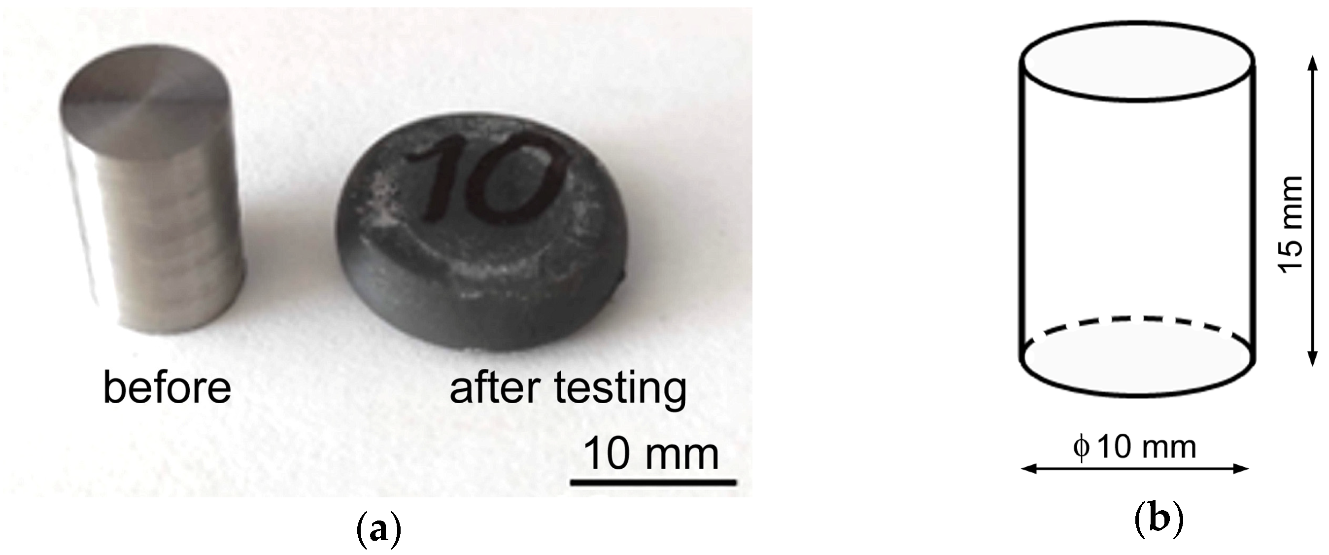
The initial workpieces were an SLM-prepared stainless-steel powder, with a particle size varying between 15 and 45 µm using an AM400 3D printer (both powder and printer by Renishaw plc., Wootton-under-Edge, UK). The maximum possible dimensions of the components produced by the AM400 printer by Renishaw were 250 × 250 × 300 mm3; the machine has the laser power of up to 400 W and enables the production of up to 20 cm3/h of material volume, according to the actual setting. The original workpieces with circular cross-sections and a 10.5 mm diameter and 160 mm length were built from left to right, with the vertical direction parallel to the building substrate, using the meander printing strategy [40,73]. The printing was performed in an inert argon (purity of 99.998%) atmosphere with an applied laser power of 200 W. The AM-prepared 316L steel workpieces were machined into a total of sixteen individual cylindrical test samples that were 10 mm in diameter and 15 mm in length. These samples were then subjected to uniaxial hot compression tests using a Gleeble 3800 thermal–mechanical simulator equipped with a Hydrawedge II Mobile Conversion Unit (both machine and equipment by Dynamic System Inc., Poestenkill, NY, USA). The tests were performed under the combined conditions of four testing temperatures (900 °C, 1000 °C, 1100 °C, and 1250 °C), and four strain rates of 0.1 s−1, 1 s−1, 10 s−1, and 100 s−1. The temperatures and strain rates were selected to cover the widest range of possible forming conditions. Hot forming usually starts at relatively high temperatures, which can progressively decrease during the forming process, depending on the selected technology. The aim of this research was to find the lowest possible temperature enabling the successful forming of the AM-prepared steel without crossing the cohesion limit. Regarding the selection of strain rates, both low and high values were investigated. Low strain rates were investigated due to the prospective future processing of the AM-prepared steel on hydraulic presses, whilst high strain rates were investigated to characterize the development of flow stress during impact forming, such as hammer forging or rotary swaging. The test samples were heated by direct electric resistance heating up to the required deformation temperature with a heating rate of 10 °C·s−1, and then deformed by uniaxial compression up to a true strain of 1.0. After the sample had been heated to the required temperature, a time dwell of 300 s was applied to homogenize the temperature throughout the sample. A time of 300 s was selected based on our experience, as it is sufficient for the temperature distribution throughout the sample to homogenize, and, at the same time, not too long to negatively influence the microstructure. Figure 1a shows an example of a sample before and after testing, and Figure 1b depicts the scheme of the testing sample with dimensions. Temperature measurement was performed using a pair of thermocouple wires (R-type (Pt-13%Rh (+) and Pt (−)) for 1250 °C, and K-type (Ni-Cr (+) and Ni-Al (−)) for 900–1100 °C) welded onto the surface of a sample, along its middle length (thermocouples by OMEGA Engineering, Norwalk, CT, USA). The testing chamber was held under vacuum to reduce oxidation, and the sample–anvil interfaces were treated with a tantalum foil coated with a nickel-based high-temperature grease to protect the anvils and reduce friction.
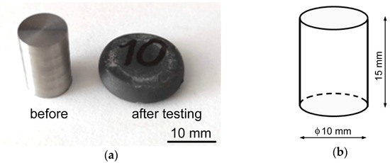
Figure 1.
Examples of samples before and after deformation (a); schematic depiction of testing sample with dimensions (b).
In order to assess the effects of different processing conditions on the microstructures and mechanical properties of the AM-prepared steel, scanning electron microscopy (SEM) and Vickers microhardness analyses were implemented. As for the SEM, Tescan Fera device equipped with an electron backscatter diffraction (EBSD) detector (equipment by Tescan Orsay Holding a.s., Brno, Czech Republic) was used. For the analysis and measurements, four samples subjected to the highest and lowest applied strain rates and temperatures were selected. To evaluate the microstructures on longitudinally (vertically) cut and processed samples, the EBSD method was used in particular. For the AM-prepared material state, a scan step of 2 µm was used, as the expected grain size was large. The processed material states, on the other hand, were scanned with a scan step of 0.1 µm, as they were expected to exhibit (highly) refined grains. For the evaluation of the data, the low- and high-angle grain boundaries (LAGBs and HAGBs) were defined using values of 5° and 15°. The microhardness was measured with a load of 1000 g (i.e., HV 1) on comparable longitudinal (vertical) sections of the deformed samples (as also further depicted graphically in Section 3.2), with an indent distance of 1 mm (FM ARS 900 equipment by Future Tech, Spectrographic Limited, Leeds, UK).
2.2. Numerical Simulation
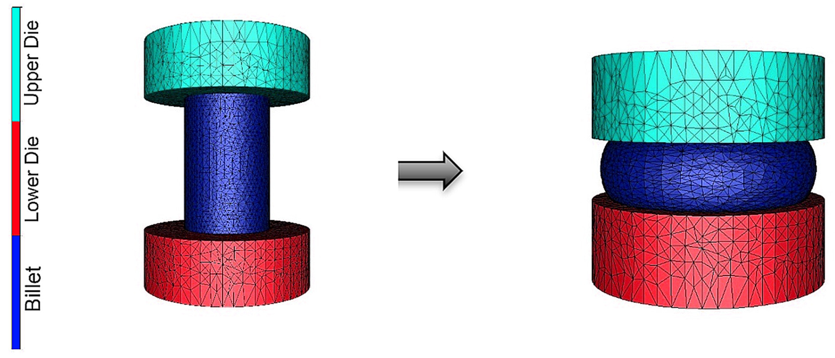
In order to complete the mapping of the formability of the AM-prepared AISI 316L steel, numerical simulations using the finite element method (FEM) were performed. The simulated task consisted of a hot compression test performed at a strain rate of 0.1 s−1 and all the four deformation temperatures of 900 °C, 1000 °C, 1100 °C, and 1250 °C. The simulations were performed using the Forge® software (NxT version, by Transvalor S.A., Biot, France). The geometric assembly of the process consisted of three objects, as depicted in Figure 2: the upper die, billet, and lower die. The dimensions of all the components corresponded to those used in the real Gleeble experiment, i.e., the test specimen diameter and height were 10 mm and 15 mm, and the anvil diameter and height were 19 mm and 6.4 mm, respectively. The anvils were considered as rigid tools. The FEM volume mesh of the billet consisted of 6315 nodes, i.e., 29,656 tetrahedron elements in total, and the mesh size was 0.53 mm. The lower and upper anvils were surface-meshed, the mesh consisted of 1008 nodes (2012 elements) for each anvil. A finer mesh with a size of 1 mm was applied in the contact area with the test specimen, as shown in Figure 2, while the other areas of the anvils were meshed with a mesh size of 2 mm.
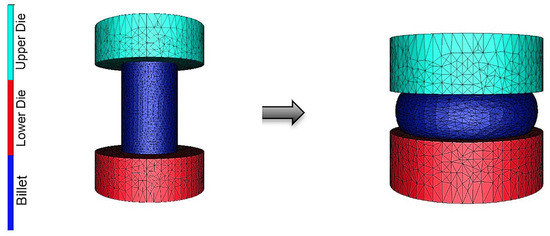
Figure 2.
FEM assembly for simulation of the hot compression test.
The behavior of the AM-prepared steel necessary for the FEM simulations was characterized via the Hensel–Spittel rheology law (Equation (1), e.g., [74,75,76]),
where ε (−) is the equivalent strain, (s−1) is the equivalent strain rate, T (K) is the temperature, and A, m1, m2, m3, m4, m5, m7, m8 and m9 are regression coefficients (−), the values of which are the following: A = 3949.693 MPa, m1 = −0.00292, m2 = −0.01398, m3 = 0.07648, m4 = −0.00854 and m5 − m9 = 0.
The Hensel–Spittel rheology law mathematically describes the experimental data obtained using the above characterized set of uniaxial hot compression tests. In other words, it describes the flow stress response of a material formed in a uniaxial stress state, i.e., a material characteristic independent of the specific applied forming technology. During FEM simulations of real forming processes, this material flow stress response can thus be used as a starting point to predict the material behavior during a selected forming process.
As for the properties of the examined material, they are summarized in the material file containing the aforementioned constants of the Hensel–Spittel equation, as well as the coefficients necessary to define the thermal properties of the studied material. In the case of the herein examined AM-prepared steel, the following constant values were considered: density ρ (7350 kg·m−3), thermal conductivity λ (33.5 W·m−1·K−1) and specific heat capacity c (678 J·kg−1·K−1). The considered value of emissivity Ε was 0.88 (selected based on our previous experience [77]). Also, to simulate the hot compression test and reliably predict the results, it is crucial to properly set the boundary conditions related to the experiment. The hot compression test was characterized by two main conditions. The first one was that the temperature during the test had to be kept constant, with the only allowable temperature change being related to the development of deformation heat. Therefore, the thermal exchange conditions between the anvils and the test specimen were defined as adiabatic, i.e., no heat transfer was considered. The second condition was that during the compression test, the displacement of the anvil was controlled to ensure a constant strain rate. The anvil feed rate during the simulations was therefore defined by Equation (2) [78],
where v (mm·s−1) is the anvil feed rate, h0 (mm) is the initial sample height, and t (s) is time.
Regarding the friction conditions on the anvil–billet interface, the nickel-based lubricant applied during the real compression test featured a friction coefficient µ of 0.15. This coefficient was thus set in the simulation, too, along with a friction factor m of 0.3 (based on the combined Coulomb–Tresca friction law). The friction condition was selected based on our previous experience, with the values used corresponding to the nickel-based high-temperature grease, which was applied during the experimental hot compression test.
3. Results and Discussion
3.1. Microstructure
3.1.1. AM-Prepared State
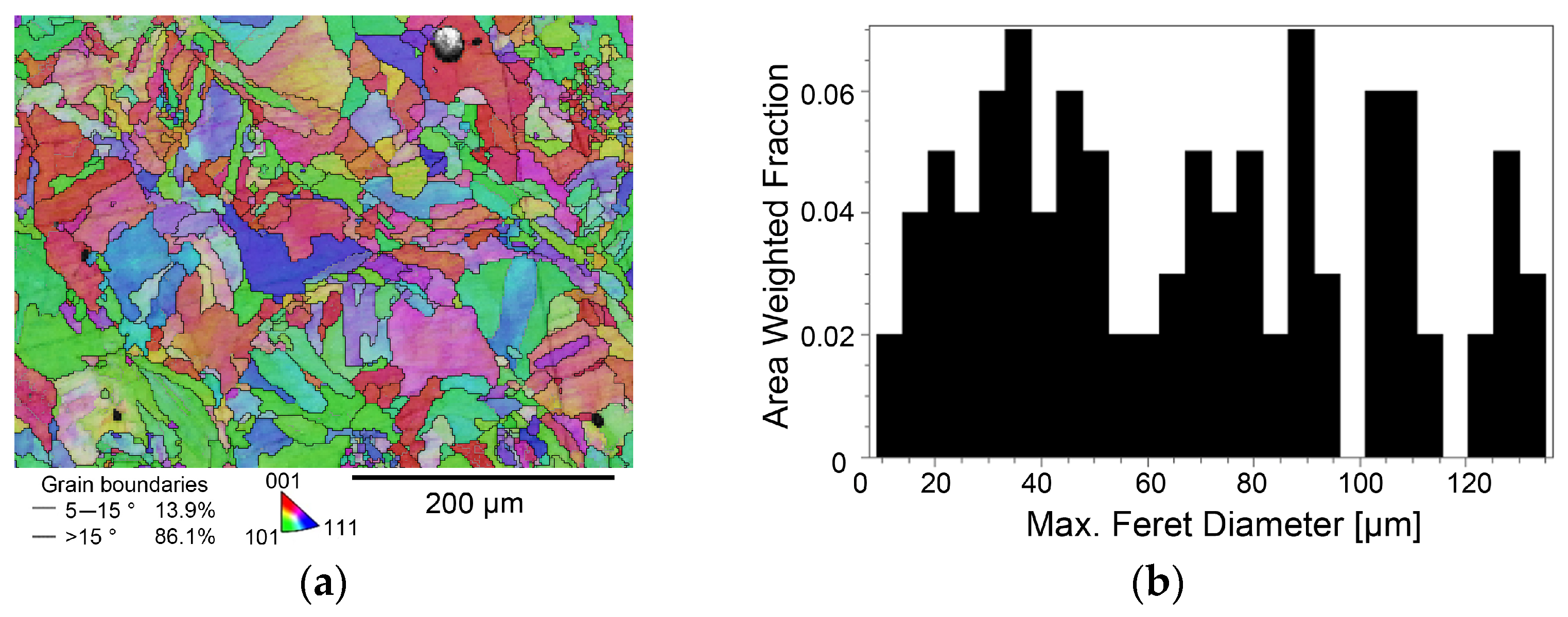
The original microstructure of the AM-prepared workpiece was characterized via the orientation image map (OIM) depicted in Figure 3a and the grain size chart depicted in Figure 3b. The grain size was evaluated using the max. feret diameter parameter in µm [79,80]. The OIM image shows that the original as-printed microstructure featured a characteristic grains morphology (melt pools), and that the grains’ orientations were more or less random, i.e., no prevailing texture was formed during the 3D printing (as was expected, see e.g., [81]). The microstructure also exhibited the presence of localized pores. The mean grain size of the AM-prepared workpiece was 32 μm; however, the sizes of the largest grains exceeded 130 μm. Figure 3a also shows that the microstructure was characterized by a dominant fraction of HAGBs, which is typical for additively manufactured steels, see e.g., [82].
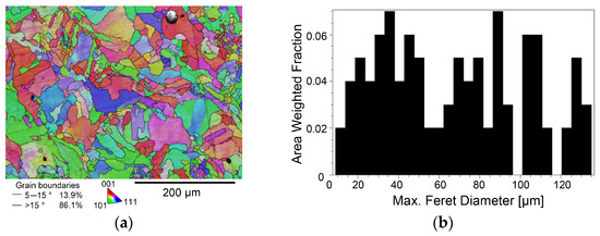
Figure 3.
Results of microstructure analysis of AM-prepared workpiece: OIM (a), grain size (b).
3.1.2. Deformed States
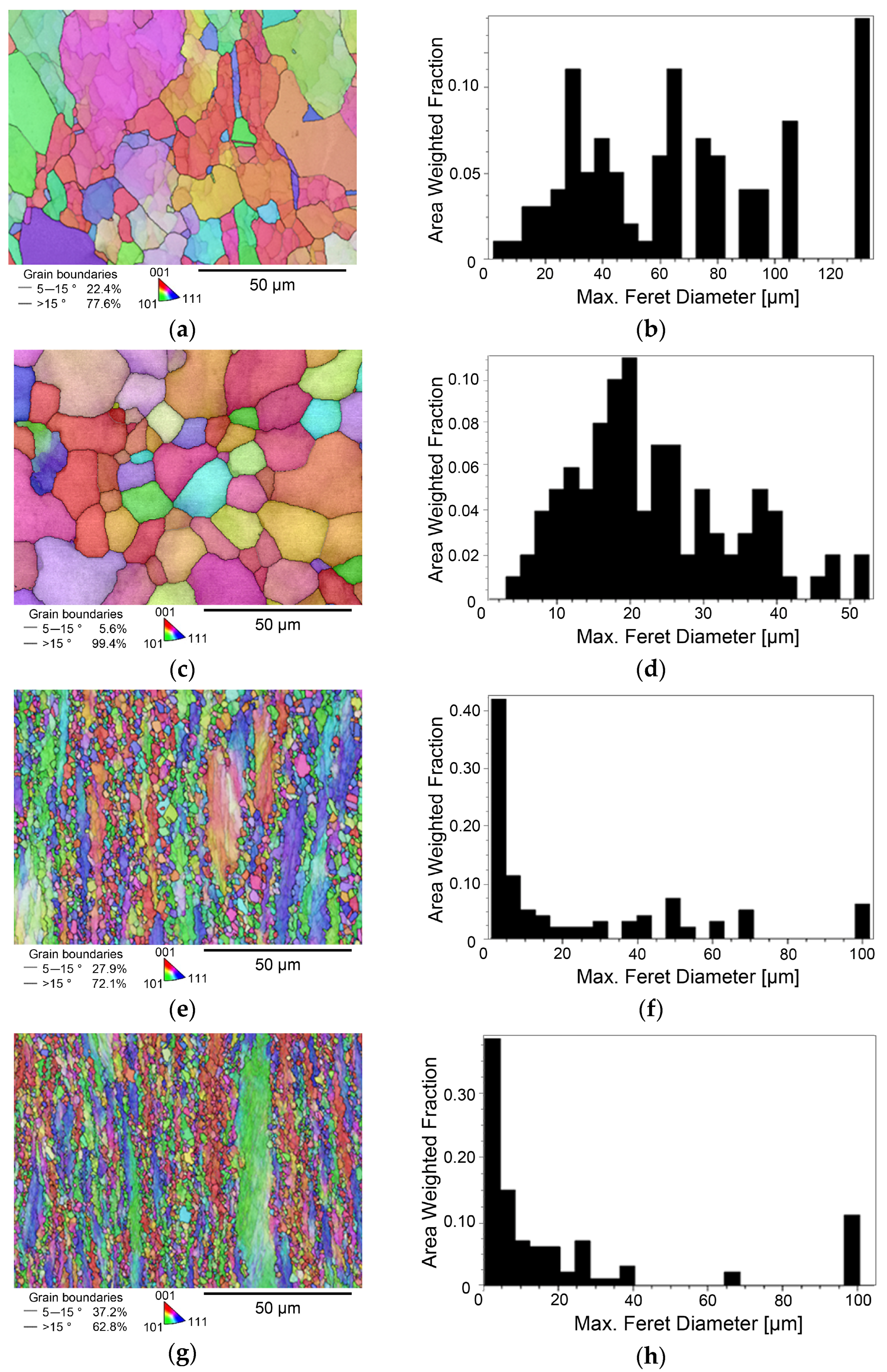
The results of the microstructure examinations of the samples subjected to hot compression testing are presented via OIM images and grain size charts, as follows: Figure 4a,b depict the OIM and grain size chart for the sample subjected to testing at 1250 °C and 0.1 s−1, Figure 4c,d depict the OIM and grain size chart for the sample subjected to testing at 1250 °C and 100 s−1, Figure 4e,f show the OIM and grain size chart for the sample subjected to testing at 900 °C and 0.1 s−1, and, finally, Figure 4g,h depict the OIM and grain size chart for the sample subjected to testing at 900 °C and 100 s−1. As can be seen from the OIM images, the majority of the grains within all the deformed samples exhibited random orientations. In other words, the deformed microstructures did not exhibit any dominant textures. All the examined samples also generally featured higher fractions of HAGBs than LAGBs. However, higher fractions of HAGBs were observed within the samples deformed at the higher temperature of 1250 °C, especially for the highest strain rate of 100 s−1, as shown in Figure 4c. For the highest strain rate, the fraction of HAGBs within the sample deformed at 1250 °C was almost 20% higher than the HAGB fraction within the one deformed at 900 °C.
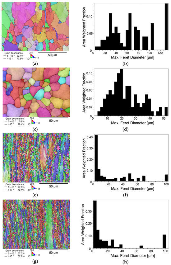
Figure 4.
Results of microstructure analyses for samples subjected to hot compression test: 1250 °C and 0.1 s−1, OIM (a), grain size chart (b); 1250 °C and 100 s−1, OIM (c), grain size chart (d); 900 °C and 0.1 s−1, OIM (e), grain size chart (f); 900 °C and 100 s−1, OIM (g), grain size chart (h).
The results of the grain size analyses (max. feret diameter in µm) showed that the microstructure of the sample subjected to the highest deformation temperature and lowest strain rate of 0.1 s−1 featured the largest mean grain size, at 21.5 µm. This finding shows that even the processing conditions allowing for the most substantial development of recrystallization, i.e., a high temperature and low strain rate [83], resulted in grain refinement compared to the original microstructure of the AM-prepared steel. Nevertheless, the sizes of the largest grains within the deformed sample still exceeded 120 µm, as shown in Figure 4b. For the sample deformed at a temperature of 1250 °C and the highest strain rate of 100 s−1, the grain refinement was even more significant; the mean grain size decreased to 10.5 µm. The largest grain size for this sample also decreased, to approximately 50 μm, as shown in Figure 4d. The grain refinement occurred due to the increased strain rate, which did not allow sufficient time for the grains to recrystallize. On the other hand, the (very) high temperature caused grain growth from the start of the test, which negatively affected the final grain refinement.
The lower deformation temperature of 900 °C led to significant grain refinement for all the applied strain rates. The mean grain size for the sample deformed at a temperature of 900 °C and strain rate of 0.1 s−1 was 2.6 µm, as shown in Figure 4f. The strain rate of 100 s−1 applied at 900 °C then resulted in the most substantial grain refinement, reducing the mean grain size down to the value of 1.3 µm, as shown in Figure 4h. However, deviations from the mean grain size were higher for the samples deformed at 900 °C than for those deformed at 1250 °C. The grains’ morphology was evidently different for the samples deformed at 900 °C and 1250 °C, too. The samples deformed at 1250 °C evidently featured great fractions of (recrystallized and) grown grains, whereas the samples deformed at 900 °C featured more developed substructures with frequent occurrences of fine recrystallized grains. While the grains within the samples deformed at 1250 °C were more or less equiaxed, the samples deformed at 900 °C featured evident necklace-like structures consisting of combinations of the original deformed grains and small recrystallized grains. A higher processing temperature of 1250 °C provided the microstructures with increased (accumulated) energy, which not only initiated and supported the development of dynamic recrystallization, but enabled also subsequent grain growth [83,84]. A lower temperature of 900 °C, on the other hand, was sufficient to initiate recrystallization, but the accumulated energy was not sufficient for subsequent grain growth, and thus the microstructures of the samples deformed at 900 °C exhibited combinations of compressed elongated original grains, as well as small refined recrystallized grains. This hypothesis also corresponds to the fact that (i) the mean grain size for the samples deformed at 900 °C was substantially smaller than that for those deformed at 1250 °C, and (ii) the fractions of HAGBs were lower for the samples deformed at 900 °C than for those deformed at 1250 °C.
3.2. Microhardness
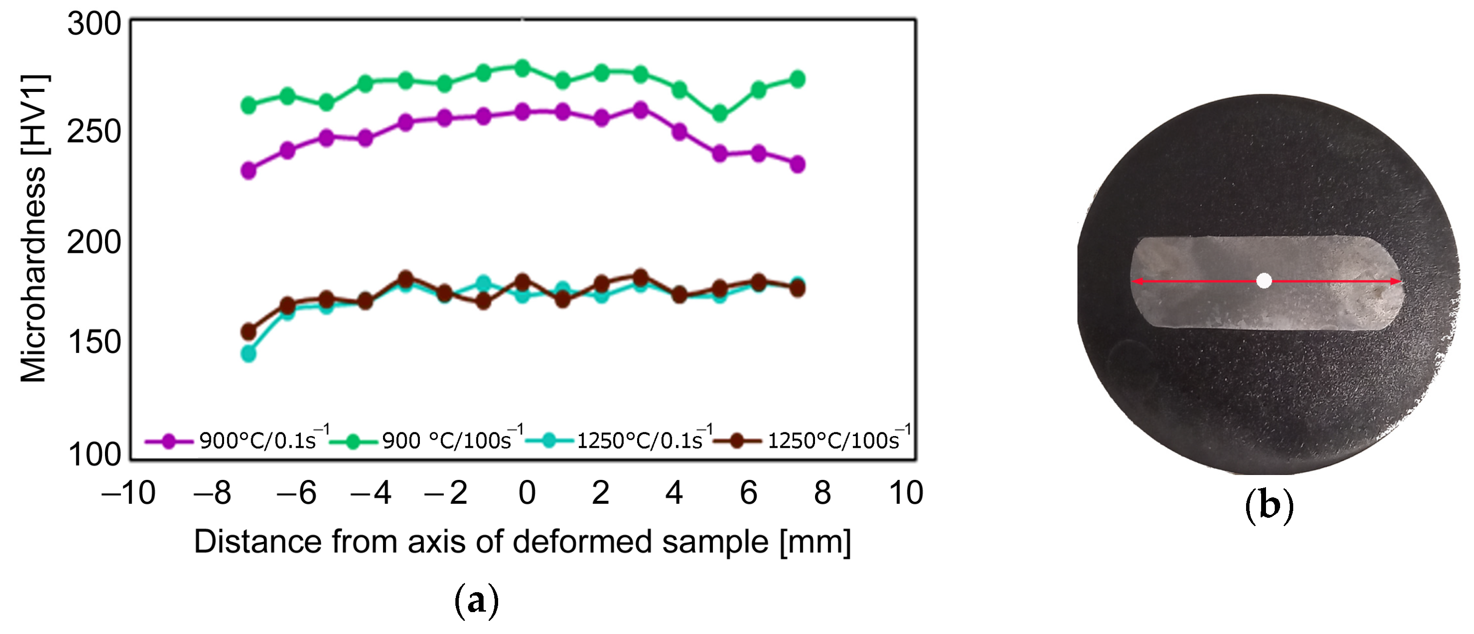
The results of the measurement of the Vickers microhardness for the samples subjected to testing at temperatures of 900 °C and 1250 °C and strain rates of 0.1 s−1 and 100 s−1 are summarized in Figure 5a. Figure 5b then shows a sample with a line drawn across its cross-section, along which the microhardness measurements were carried out. The average Vickers microhardness for the AM-prepared workpiece was 218.1 HV1. The HV1 values did not exhibit any decreasing/increasing trend across the workpiece cross-section, only local decreases which could be attributed to the localized porosity, as seen in Figure 3a. Figure 5a then shows that both the samples deformed at 1250 °C exhibited comparable microhardness values, with no visible increasing/decreasing trend across the cross-sections; the average microhardness value for both the samples was 171.4 HV1. For the sample deformed at a deformation temperature of 900 °C and strain rate of 0.1 s−1, the average microhardness increased and reached the value of 243.5 HV1, and the highest microhardness of 269.7 HV1 was acquired for the sample deformed at a temperature of 900 °C and strain rate of 100 s−1. The microhardness ranged from 140 HV1 to 190 HV1 at a deformation temperature of 1250 °C, and from 230 HV1 to 280 HV1 at a deformation temperature of 900 °C. Forming at lower temperatures thus obviously resulted in higher microhardness values. It is also evident that the strain rate significantly affected the microhardness at a deformation temperature of 900 °C, while its effect was negligible at a temperature of 1250 °C. The acquired results thus confirm the results of the microstructure observations discussed above. Both the samples deformed at a temperature of 900 °C exhibited increased microhardness, which corresponds to the observed substantial grain refinement and presence of ultra-fine grains within the microstructure [85,86,87]. Processing at 1250 °C substantially supported softening via dynamic recrystallization, the formation of relaxed grains and consequent grain growth, which contributed to decreased microhardness. Despite the fact that the grains were refined after processing at 1250 °C, the grain size was not small enough and the dislocation density was not high enough to increase the microhardness. The highest value of microhardness was acquired for the sample deformed at 900 °C and the highest strain rate of 100 s−1, which corresponds to the hypothesis that combinations of lower deformation temperatures and higher strain rates tend to lead to substantial substructure development and work hardening [84].
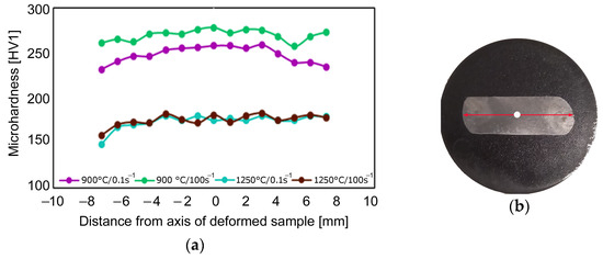
Figure 5.
Vickers microhardness of examined samples (a); sample with depiction of location of microhardness measurement (red line across diameter) (b).
3.3. Flow Stress
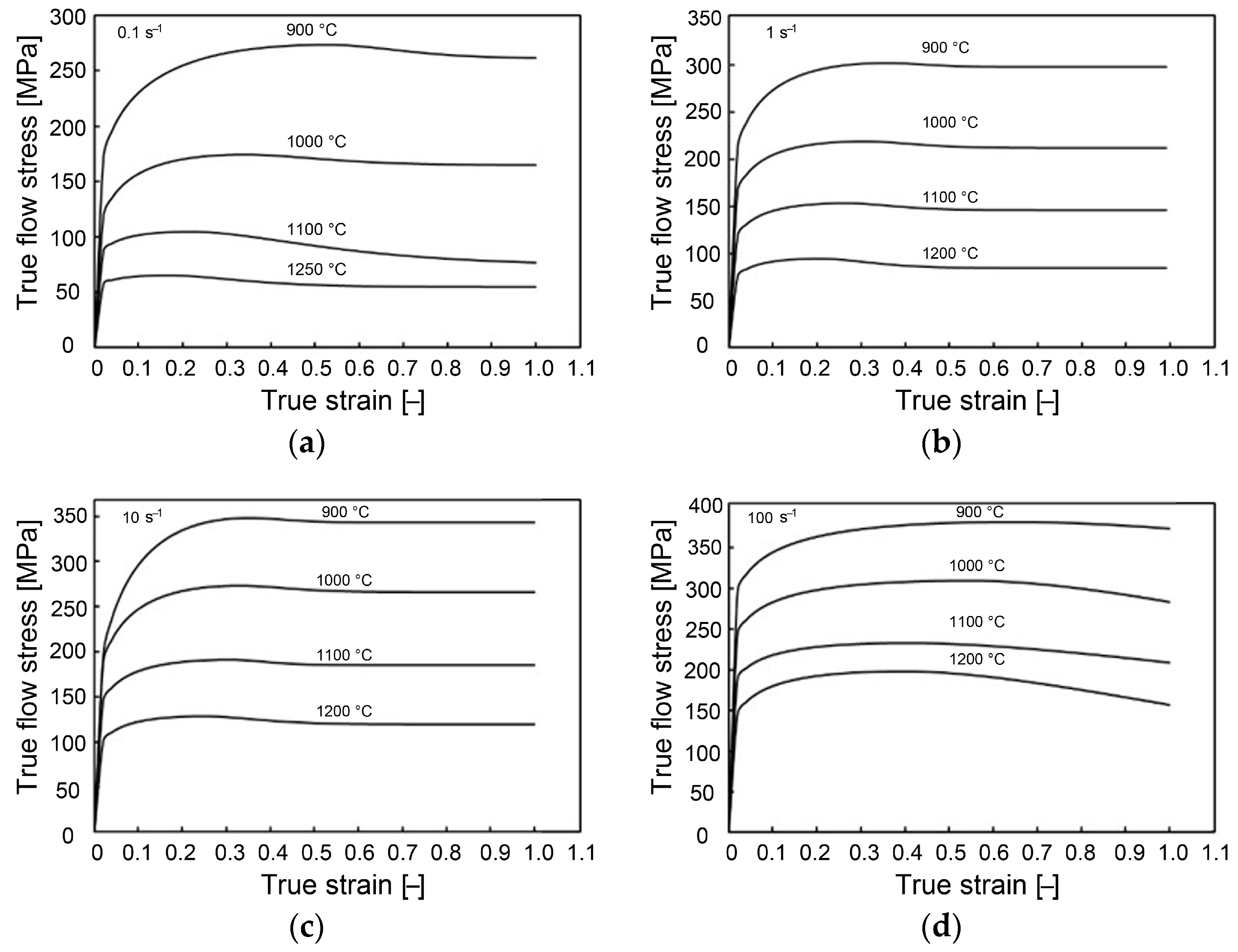
Figure 6a–d depict the flow stress curves characterizing the development of material flow stress in the AM-prepared steel through the entire range of applied temperatures at strain rates of 0.1 s−1, 1 s−1, 10 s−1, and 100 s−1, respectively. The figures show that the achieved maximum flow stress generally increased with decreasing temperature and increasing strain rate, which is rather typical, see e.g., [88,89,90]. A higher strain rate in combination with a higher deformation temperature generally favorably influenced the formability. This finding was supported by the fact that the stress–strain curves acquired during testing at the highest strain rate, as shown in Figure 6d, did not exhibit any signs of dynamic recrystallization occurring. The initiation of dynamic recrystallization could be most notably seen at the curves acquired for the lowest deformation temperature. Figure 6a–c clearly show that the critical (peak) imposed strain necessary to initiate dynamic recrystallization decreased with an increase in the strain rate applied. In other words, a lower applied strain rate supported the development of dynamic recrystallization, when considering identical deformation temperatures. The maximum acquired flow stress, achieved for the sample deformed at 900 °C and 100 s−1, was approximately 380 MPa. The acquired results can be compared, for example, with those acquired by Liu et al. [71] and Khodabakhshi et al. [72], similarly investigating AM-prepared AISI 316L steel samples. The researchers observed similar trends regarding the flow stress behavior, and reported that dynamic recrystallization within the AM-prepared AISI 316L steel occurred to higher extents at high processing temperatures, while lower processing temperatures decreased formability and led to the increased occurrence of cracks. Evidently, high strain rates combined with high deformation temperatures minimize surface cracking during processing due to the occurrence of dynamic recrystallization to a sufficient extent.
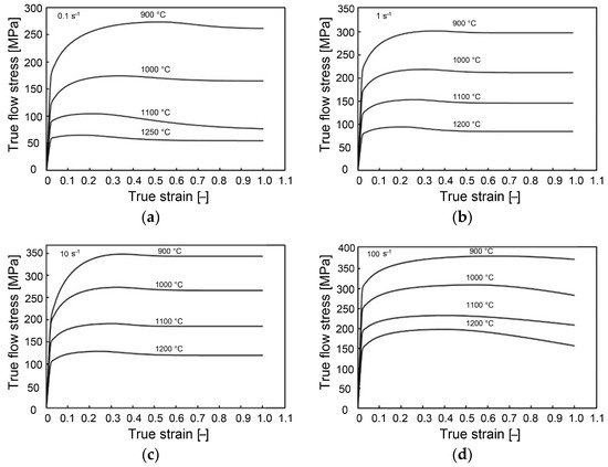
Figure 6.
Experimental flow stress curves for four strain rates combined with each examined temperature: 0.1 s−1 (a); 1 s−1 (b); 10 s−1 (c); 100 s−1 (d).
Considering that the original AM-prepared AISI 316L steel is subjected to post-processing via hot rotary swaging, which is characterized by (very) high strain rates, optimized combinations of processing conditions based on this research will most probably offer a satisfactory solution to the reduction/elimination of the aforementioned disadvantages of AM technologies and result in the fabrication of AISI 316L steel components with enhanced performance.
3.4. Numerical Prediction
3.4.1. Deformation Forces
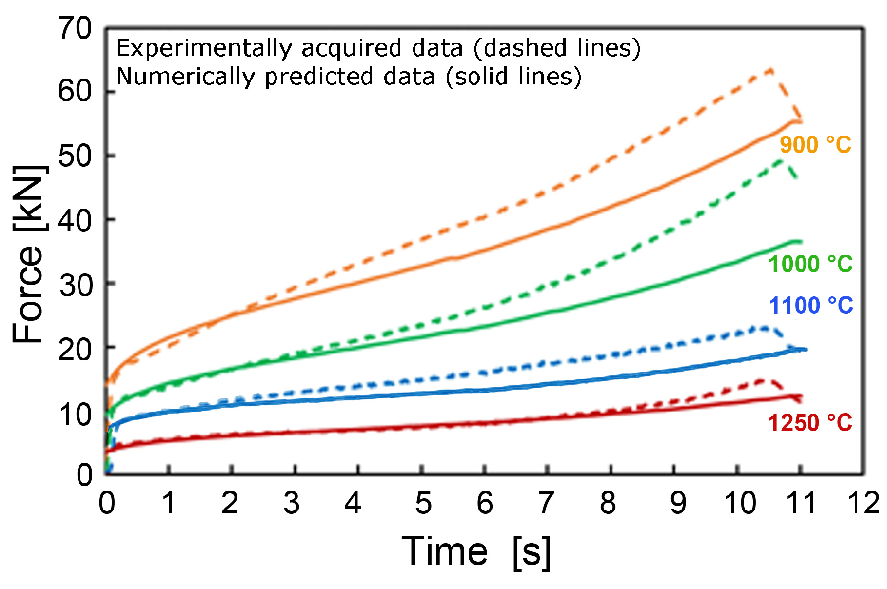
Figure 7 shows a comparison of the experimentally acquired and predicted dependencies of deformation force on the testing time for the examined samples (dashed curves depict the experimental results, while solid curves depict the predicted ones). Considering the maximum force, the predicted curves obviously exhibited trends comparable to the experimentally acquired ones, i.e., the maximum force increased as the testing temperature decreased. The highest force, both experimental and numerically predicted, was acquired when testing at 900 °C; the maximum experimentally measured force at 900 °C was approximately 65 kN. Nevertheless, the experimentally acquired curves generally featured higher force values compared to the predicted ones, and the difference between these two curves decreased towards an increasing processing temperature.
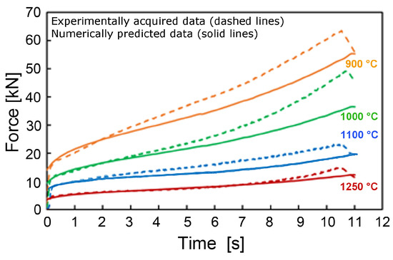
Figure 7.
Comparison of experimental and numerically predicted forces for examined samples at strain rate of 0.1 s−1.
The differences observed between the experimentally acquired and numerically predicted force values can most probably be attributed to the defined boundary conditions (e.g., differences in the friction conditions on the contact surfaces between the anvils and sample, etc.). The numerical simulation considered the constant condition of perfect lubrication during the entire test. In the experimental conditions, on the other hand, the lubricant was gradually squeezed out and, in addition, partially lost by evaporation due to high testing temperatures, which could result in higher friction forces, i.e., higher overall deformation forces measured in the experimental conditions. Another important factor influencing the deformation force is the homogeneity of temperature distribution, which evidently played a non-negligible role during testing at all the deformation temperatures. As can be seen from Figure 7 (and stated above), the difference between the experimentally acquired and predicted curves, especially towards the end of the test, decreased with increasing processing temperature. Regarding the influence of strain rate on the mechanical properties, there are two aspects. From the viewpoint of the mutual fit between the experimentally obtained and predicted curves for compression force under an identical temperature, there are only negligible differences with increasing strain. On the other hand, the curves gained an increasing character with an increasing strain rate. This made the individual curves steeper, i.e., there was a faster increase in the deformation force and overall higher values at all the testing temperatures. The reasons for the similar behavior is the shorter time needed for the activation and development of dynamic softening processes and the dynamic work hardening being faster, based on the very intensive accumulation of dislocations.
3.4.2. Equivalent Strain
Last but not least, the results of the predicted distributions of equivalent strain for the testing temperatures ranging from 900 °C to 1250 °C and strain rate of 0.1 s−1 are shown in Figure 8. For clarity, three distinct locations, characterized as location 1 (top surface of a sample), location 2 (axial region of a sample), and location 3 (lateral edge surface of a sample), are used for the samples. As can be seen in Figure 8, the distribution and magnitudes of the imposed strain were comparable for all the testing temperatures. The highest imposed strain within the bulk of all the samples (approximately 1.8) was observed in location 2, while location 1 generally exhibited the lowest strain values (≤0.4). This corresponds to the effect of friction forces hindering the material plastic flow in the vicinity of the anvil-sample contact surfaces. In location 3, the imposed strain reached a value of approximately 1 for all the samples. The figure also shows that the temperature did not have any major effect on the distribution and magnitude of the equivalent strain. However, the maximum strain at higher temperatures was slightly lower, which was most probably related to the different nature of the material plastic flow (as discussed in the previous sections). The lower strain value can most probably be directly related to the previously mentioned occurring dynamic softening of the AM-prepared AISI 316L.

Figure 8.
Equivalent strain at four temperatures at a strain rate of 0.1 s−1, numbers 1, 2, and 3 correspond to location 1, location 2, and location 3.
4. Conclusions
This study focused on the experimental and numerical characterization of the deformation behavior of AM-prepared AISI 316L stainless steel in order to find the most suitable conditions for prospective thermomechanical post-processing. The most prominent results are the following:
- -
- Higher deformation temperatures, especially in combination with lower strain rates, supported recrystallization and grain growth, while lower deformation temperatures supported grain refinement and the development of a substructure, resulting in work hardening;
- -
- The deformation force and flow stress increased with a decreasing processing temperature, with maximum values of approximately 65 kN and 380 MPa, respectively, being acquired at 900 °C;
- -
- Deformation at 900 °C and 100 s−1 resulted in the smallest mean grain size of 1.3 µm and highest average microhardness of 270 HV1;
- -
- Despite a decrease in microhardness due to recrystallization and subsequent grain growth, deformation at 1250 °C resulted in grain refinement to a mean size of 21.5 µm.
The primary novelty of the presented research lies in the fact that the most favorable conditions for the prospective deformation (thermomechanical) post-processing of AM-prepared 316L stainless steel were given, and that it considered various viewpoints. Such post-processing will be the most favorable when performed at a temperature of 900 °C, from the viewpoint of mechanical properties, and higher strain rates, from the viewpoint of formability. The proposed combinations of higher temperatures and strain rates seem to be optimal for forming processes featuring high strain rates, such as rotary swaging. Nevertheless, the performed study confirmed that processing at the relatively low forming temperature of 900 °C is still feasible, and can provide favorable results. Future research, during which the acquired results will be applied, will be focused on the experimental post-processing of AM-prepared stainless steel workpieces using industrial processing methods and the verification of the acquired results under real conditions.
Author Contributions
Conceptualization, data curation, investigation, writing—original draft preparation: L.K.; investigation, project administration, funding acquisition, writing—review and editing: R.K.; resources, methodology: M.P. All authors have read and agreed to the published version of the manuscript.
Funding
Statement: This research was supported by SP2024/089 project by VŠB Technical Univerzity of Ostrava.
Data Availability Statement
The original contributions presented in this study are included in the article. Further inquiries can be directed to the corresponding author.
Acknowledgments
The assistance of Petr Opěla, Marek Benč, and Josef Walek (all Department of Metallurgical Technologies, Faculty of Materials Science and Technology, VŠB-Technical University of Ostrava) during the experimental works is appreciated.
Conflicts of Interest
The authors declare no conflicts of interest.
References
- Sun, J.; Ye, D.; Zou, J.; Chen, X.; Wang, Y.; Yuan, J.; Liang, H.; Qu, H.; Binner, J.; Bai, J. A Review on Additive Manufacturing of Ceramic Matrix Composites. J. Mater. Sci. Technol. 2023, 138, 1–16. [Google Scholar] [CrossRef]
- Vaezi, M.; Seitz, H.; Yang, S. A Review on 3D Micro-Additive Manufacturing Technologies. Int. J. Adv. Manuf. Technol. 2012, 67, 1721–1754. [Google Scholar] [CrossRef]
- Das, T.; Mukherjee, M.; Chatterjee, D.; Samanta, S.K.; Lohar, A.K. A Comparative Evaluation of the Microstructural Characteristics of L-DED and W-DED Processed 316L Stainless Steel. CIRP J. Manuf. Sci. Technol. 2023, 40, 114–128. [Google Scholar] [CrossRef]
- Gorunov, A.I. Additive Manufacturing of Ti6Al4V Parts Using Ultrasonic Assisted Direct Energy Deposition. J. Manuf. Process. 2020, 59, 545–556. [Google Scholar] [CrossRef]
- Kocich, R.; Kunčická, L.; Benč, M.; Weiser, A.; Németh, G. Corrosion Behavior of Selective Laser Melting-Manufactured Bio-Applicable 316L Stainless Steel in Ionized Simulated Body Fluid. Int. J. Bioprint. 2024, 10, 1416. [Google Scholar] [CrossRef]
- Puga, B.; Lomello, F.; Boussac, E.; Chniouel, A.; Fouchereau, A.; Laghoutaris, P.; Maskrot, H. Influence of Laser Powder Bed Fusion Processing Parameters on Corrosion Behaviour of 316L Stainless Steel in Nitric Acid. Metall. Res. Technol. 2022, 119, 523. [Google Scholar] [CrossRef]
- Kazantseva, N.; Krakhmalev, P.; Yadroitsev, I.; Fefelov, A.; Merkushev, A.; Ilyinikh, M.; Vinogradova, N.; Ezhov, I.; Kurennykh, T. Oxygen and Nitrogen Concentrations in the Ti-6Al-4V Alloy Manufactured by Direct Metal Laser Sintering (DMLS) Process. Mater. Lett. 2017, 209, 311–314. [Google Scholar] [CrossRef]
- Gong, H.; Rafi, K.; Gu, H.; Janaki Ram, G.D.; Starr, T.; Stucker, B. Influence of Defects on Mechanical Properties of Ti–6Al–4V Components Produced by Selective Laser Melting and Electron Beam Melting. Mater. Des. 2015, 86, 545–554. [Google Scholar] [CrossRef]
- Rajaguru, K.; Karthikeyan, T.; Vijayan, V. Additive Manufacturing–State of Art. Mater. Today Proc. 2020, 21, 628–633. [Google Scholar] [CrossRef]
- Savrai, R.A.; Toporova, D.V.; Bykova, T.M. Improving the Quality of AISI H13 Tool Steel Produced by Selective Laser Melting. Opt. Laser Technol. 2022, 152, 108128. [Google Scholar] [CrossRef]
- Bakradze, M.M.; Rogalev, A.M.; Sukhov, D.I.; Aslanyan, G.G. Special Features of Formation of Surface by Selective Laser Melting. Met. Sci. Heat Treat. 2022, 64, 108–116. [Google Scholar] [CrossRef]
- Aboulkhair, N.T.; Simonelli, M.; Parry, L.; Ashcroft, I.; Tuck, C.; Hague, R. 3D Printing of Aluminium Alloys: Additive Manufacturing of Aluminium Alloys Using Selective Laser Melting. Prog. Mater. Sci. 2019, 106, 100578. [Google Scholar] [CrossRef]
- Tarasova, T.; Gvozdeva, G.; Ableyeva, R. Aluminium Matrix Composites Produced by Laser Based Additive Manufacturing. Mater. Today Proc. 2019, 11, 305–310. [Google Scholar] [CrossRef]
- Karlsson, J.; Sjogren, T.; Snis, A.; Engqvist, H.; Lausmaa, J. Digital Image Correlation Analysis of Local Strain Fields on Ti6Al4V Manufactured by Electron Beam Melting. Mater. Sci. Eng. A 2014, 618, 456–461. [Google Scholar] [CrossRef]
- Nocivin, A.; Raducanu, D.; Vasile, B.; Trisca-Rusu, C.; Cojocaru, E.M.; Dan, A.; Irimescu, R.; Cojocaru, V.D. Tailoring a Low Young Modulus for a Beta Titanium Alloy by Combining Severe Plastic Deformation with Solution Treatment. Materials 2021, 14, 3467. [Google Scholar] [CrossRef] [PubMed]
- Cherry, J.A.; Davies, H.M.; Mehmood, S.; Lavery, N.P.; Brown, S.G.R.; Sienz, J. Investigation into the Effect of Process Parameters on Microstructural and Physical Properties of 316L Stainless Steel Parts by Selective Laser Melting. Int. J. Adv. Manuf. Technol. 2015, 76, 869–879. [Google Scholar] [CrossRef]
- Shchitsyn, Y.D.; Terentev, S.A.; Neulybin, S.D.; Artyomov, A.O. Formation of 04Cr18Ni9 Steel Structure and Properties during Additive Manufacturing of Blanks. Int. J. Adv. Manuf. Technol. 2019, 102, 3719–3723. [Google Scholar] [CrossRef]
- Moskvina, V.A.; Melnikov, E.V.; Astafurov, S.V.; Panchenko, M.Y.; Reunova, K.A.; Kolubaev, E.A.; Astafurova, E.G. Stable High-Nickel Austenitic Steel Produced by Electron Beam Additive Manufacturing Using Dual Wire-Feed System. Mater. Lett. 2021, 305, 130863. [Google Scholar] [CrossRef]
- Astafurov, S.; Astafurova, E. Phase Composition of Austenitic Stainless Steels in Additive Manufacturing: A Review. Metals 2021, 11, 1052. [Google Scholar] [CrossRef]
- Kuzminova, Y.; Shibalova, A.; Evlashin, S.; Shishkovsky, I.; Krakhmalev, P. Structural Effect of Low Al Content in the In-Situ Additive Manufactured CrFeCoNiAlx High-Entropy Alloy. Mater. Lett. 2021, 303, 130487. [Google Scholar] [CrossRef]
- Kuzminova, Y.O.; Kudryavtsev, E.A.; Han, J.-K.; Kawasaki, M.; Evlashin, S.A. Phase and Structural Changes during Heat Treatment of Additive Manufactured CrFeCoNi High-Entropy Alloy. J. Alloys Compd. 2021, 889, 161495. [Google Scholar] [CrossRef]
- Krinitcyn, M.; Kopytov, G.; Ryumin, E. Additive Manufacturing of Ti3AlC2/TiC and Ti3AlC2/SiC Ceramics Using the Fused Granules Fabrication Technique. J. Manuf. Mater. Process. 2024, 8, 123. [Google Scholar] [CrossRef]
- Tamburrino, F.; Barone, S.; Paoli, A.; Razionale, A.V. Post-Processing Treatments to Enhance Additively Manufactured Polymeric Parts: A Review. Virtual Phys. Prototyp. 2021, 16, 221–254. [Google Scholar] [CrossRef]
- Nguyen, H.D.; Pramanik, A.; Basak, A.K.; Dong, Y.; Prakash, C.; Debnath, S.; Shankar, S.; Jawahir, I.S.; Dixit, S.; Buddhi, D. A Critical Review on Additive Manufacturing of Ti-6Al-4V Alloy: Microstructure and Mechanical Properties. J. Mater. Res. Technol. 2022, 18, 4641–4661. [Google Scholar] [CrossRef]
- Utyaganova, V.R.; Filippov, A.V.; Shamarin, N.N.; Vorontsov, A.V.; Savchenko, N.L.; Fortuna, S.V.; Gurianov, D.A.; Chumaevskii, A.V.; Rubtsov, V.E.; Tarasov, S.Y. Controlling the Porosity Using Exponential Decay Heat Input Regimes during Electron Beam Wire-Feed Additive Manufacturing of Al-Mg Alloy. Int. J. Adv. Manuf. Technol. 2020, 108, 2823–2838. [Google Scholar] [CrossRef]
- Levin, V.A.; Zingerman, K.M.; Vershinin, A.V.; Konovalov, D.A. Numerical Modeling of Residual Stresses in Additive Manufacturing Products Using the Theory of Repeatedly Superimposed Finite Strains. Math. Mech. Solids 2022, 27, 2099–2109. [Google Scholar] [CrossRef]
- Babaev, A.; Promakhov, V.; Schulz, N.; Semenov, A.; Bakhmat, V.; Vorozhtsov, A. Processes of Physical Treatment of Stainless Steels Obtained by Additive Manufacturing. Metals 2022, 12, 1449. [Google Scholar] [CrossRef]
- Aboulkhair, N.T.; Maskery, I.; Tuck, C.; Ashcroft, I.; Everitt, N.M. Improving the Fatigue Behaviour of a Selectively Laser Melted Aluminium Alloy: Influence of Heat Treatment and Surface Quality. Mater. Des. 2016, 104, 174–182. [Google Scholar] [CrossRef]
- Popovich, V.A.; Borisov, E.V.; Popovich, A.A.; Sufiiarov, V.S.; Masaylo, D.V.; Alzina, L. Impact of Heat Treatment on Mechanical Behaviour of Inconel 718 Processed with Tailored Microstructure by Selective Laser Melting. Mater. Des. 2017, 131, 12–22. [Google Scholar] [CrossRef]
- Teixeira, Ó.; Silva, F.J.G.; Ferreira, L.P.; Atzeni, E. A Review of Heat Treatments on Improving the Quality and Residual Stresses of the Ti–6Al–4V Parts Produced by Additive Manufacturing. Metals 2020, 10, 1006. [Google Scholar] [CrossRef]
- Peng, X.; Kong, L.; Fuh, J.Y.H.; Wang, H. A Review of Post-Processing Technologies in Additive Manufacturing. J. Manuf. Mater. Process. 2021, 5, 38. [Google Scholar] [CrossRef]
- Mclean, N.; Bermingham, M.J.; Colegrove, P.; Sales, A.; Soro, N.; Ng, C.H.; Dargusch, M.S. Effect of Hot Isostatic Pressing and Heat Treatments on Porosity of Wire Arc Additive Manufactured Al 2319. J. Mater. Process. Technol. 2022, 310, 117769. [Google Scholar] [CrossRef]
- Petrovskiy, P.; Travyanov, A.; Cheverikin, V.V.; Chereshneva, A.A.; Sova, A.; Smurov, I. Effect of Encapsulated Hot Isostatic Pressing on Properties of Ti6Al4V Deposits Produced by Cold Spray. Int. J. Adv. Manuf. Technol. 2020, 107, 437–449. [Google Scholar] [CrossRef]
- Krakhmalev, P.; Fredriksson, G.; Thuvander, M.; Åsberg, M.; Vilardell, A.M.; Oikonomou, C.; Maistro, G.; Medvedeva, A.; Kazantseva, N. Influence of Heat Treatment under Hot Isostatic Pressing (HIP) on Microstructure of Intermetallic-Reinforced Tool Steel Manufactured by Laser Powder Bed Fusion. Mater. Sci. Eng. A 2020, 772, 138699. [Google Scholar] [CrossRef]
- Wang, Z.; Chen, J.; Kocich, R.; Tardif, S.; Dolbnya, I.P.; Kunčická, L.; Micha, J.-S.; Liogas, K.; Magdysyuk, O.V.; Szurman, I.; et al. Grain Structure Engineering of NiTi Shape Memory Alloys by Intensive Plastic Deformation. ACS Appl. Mater. Interfaces 2022, 14, 31396–31410. [Google Scholar] [CrossRef]
- Strunz, P.; Kunčická, L.; Beran, P.; Kocich, R.; Hervoches, C. Correlating Microstrain and Activated Slip Systems with Mechanical Properties within Rotary Swaged WNiCo Pseudoalloy. Materials 2020, 13, 208. [Google Scholar] [CrossRef]
- Kunčická, L.; Kocich, R. Effect of Activated Slip Systems on Dynamic Recrystallization during Rotary Swaging of Electro-Conductive Al-Cu Composites. Mater. Lett. 2022, 321, 10–13. [Google Scholar] [CrossRef]
- Shi, X.; Hussain, G.; Zha, G.; Wu, M.; Kong, F. Study on Formability of Vertical Parts Formed by Multi-Stage Incremental Forming. Int. J. Adv. Manuf. Technol. 2014, 75, 1049–1053. [Google Scholar] [CrossRef]
- Vihtonen, L.; Puzik, A.; Katajarinne, T. Comparing Two Robot Assisted Incremental Forming Methods: Incremental Forming by Pressing and Incremental Hammering. Int. J. Mater. Form. 2008, 1, 1207–1210. [Google Scholar] [CrossRef]
- Kunčická, L.; Kocich, R.; Németh, G.; Dvořák, K.; Pagáč, M. Effect of Post Process Shear Straining on Structure and Mechanical Properties of 316 L Stainless Steel Manufactured via Powder Bed Fusion. Addit. Manuf. 2022, 59, 103128. [Google Scholar] [CrossRef]
- Canelo-Yubero, D.; Kocich, R.; Hervoches, C.; Strunz, P.; Kunčická, L.; Krátká, L. Neutron Diffraction Study of Residual Stresses in a W–Ni–Co Heavy Alloy Processed by Rotary Swaging at Room and High Temperatures. Met. Mater. Int. 2022, 28, 919–930. [Google Scholar] [CrossRef]
- Lukáč, P.; Kocich, R.; Greger, M.; Padalka, O.; Szaraz, Z. Microstructure of AZ31 and AZ61 Mg Alloys Prepared by Rolling and ECAP. Kov. Mater. Mater. 2007, 45, 115–120. [Google Scholar]
- Volokitina, I.E. Evolution of the Microstructure and Mechanical Properties of Copper under ECAP with Intense Cooling. Met. Sci. Heat Treat. 2020, 62, 253–258. [Google Scholar] [CrossRef]
- Segal, V. Review: Modes and Processes of Severe Plastic Deformation (SPD). Materials 2018, 11, 1175. [Google Scholar] [CrossRef]
- Kunčická, L.; Kocich, R.; Drápala, J.; Andreyachshenko, V.A. FEM Simulations and Comparison of the Ecap and ECAP-PBP Influence on Ti6Al4V Alloy’s Deformation Behaviour. In Proceedings of the METAL 2013-22nd International Conference on Metallurgy and Materials, Conference Proceedings, Brno, Czech Republic, 15–17 May 2013; pp. 391–396. [Google Scholar]
- Xia, K.; Wu, X. Back Pressure Equal Channel Angular Consolidation of Pure Al Particles. Scr. Mater. 2005, 53, 1225–1229. [Google Scholar] [CrossRef]
- Kunčická, L.; Kocich, R.; Ryukhtin, V.; Cullen, J.C.T.; Lavery, N.P. Study of Structure of Naturally Aged Aluminium after Twist Channel Angular Pressing. Mater. Charact. 2019, 152, 94–100. [Google Scholar] [CrossRef]
- Kocich, R.; Kunčická, L. Development of Structure and Properties in Bimetallic Al/Cu Sandwich Composite during Cumulative Severe Plastic Deformation. J. Sandw. Struct. Mater. 2021, 23, 4252–4275. [Google Scholar] [CrossRef]
- Kocich, R.; Kunčická, L. Optimizing Structure and Properties of Al/Cu Laminated Conductors via Severe Shear Strain. J. Alloys Compd. 2023, 953, 170124. [Google Scholar] [CrossRef]
- Fu, Z.; Gao, B.; Li, X.; Li, C.; Pan, H.; Niu, H.; Zhu, Y.; Zhou, H.; Zhu, X.; Wu, H.; et al. Improved Strength-Ductility Combination of Pure Zr by Multi-Scale Heterostructured Effects via Rotary Swaging and Annealing. Mater. Sci. Eng. A 2023, 864, 144584. [Google Scholar] [CrossRef]
- Rybalchenko, O.; Torganchuk, V.; Rybalchenko, G.; Martynenko, N.; Lukyanova, E.; Tokar, A.; Prosvirnin, D.; Yusupov, V.; Dobatkin, S. Effect of Rotary Swaging on Microstructure and Properties of Cr-Ni-Ti Austenitic Stainless Steel. Metals 2023, 13, 1760. [Google Scholar] [CrossRef]
- Xie, X.; Jiang, W.; Chen, J.; Zhang, X.; Tu, S.-T. Cyclic Hardening/Softening Behavior of 316L Stainless Steel at Elevated Temperature Including Strain-Rate and Strain-Range Dependence: Experimental and Damage-Coupled Constitutive Modeling. Int. J. Plast. 2019, 114, 196–214. [Google Scholar] [CrossRef]
- Lee, S.; Ghiaasiaan, R.; Gradl, P.R.; Shao, S.; Shamsaei, N. Additively Manufactured 316L Stainless Steel via Laser Powder Directed Energy Deposition (LP-DED): Mechanical Properties at Cryogenic and Elevated Temperatures. Int. J. Fatigue 2024, 182, 108197. [Google Scholar] [CrossRef]
- Behvar, A.; Aghayar, Y.; Avateffazeli, M.; Tridello, A.; Benelli, A.; Paolino, D.S.; Mohammadi, M.; Haghshenas, M. Synergistic Impact of Corrosion Pitting on the Rotating Bending Fatigue of Additively Manufactured 316L Stainless Steel: Integrated Experimental and Modeling Analyses. Int. J. Fatigue 2024, 188, 108491. [Google Scholar] [CrossRef]
- Abramov, A.V.; Polovov, I.B.; Volkovich, V.A.; Rebrin, O.I.; Denisov, E.I.; Griffiths, T.R. Corrosion of Austenitic Steels and Their Components in Vanadium-Containing Chloride Melts. ECS Trans. 2013, 50, 685–698. [Google Scholar] [CrossRef]
- Zach, L.; Kunčická, L.; Růžička, P.; Kocich, R. Design, Analysis and Verification of a Knee Joint Oncological Prosthesis Finite Element Model. Comput. Biol. Med. 2014, 54, 53–60. [Google Scholar] [CrossRef]
- Kunčická, L.; Kocich, R.; Lowe, T.C. Advances in Metals and Alloys for Joint Replacement. Prog. Mater. Sci. 2017, 88, 232–280. [Google Scholar] [CrossRef]
- Macháčková, A.; Kocich, R.; Bojko, M.; Kunčická, L.; Polko, K. Numerical and Experimental Investigation of Flue Gases Heat Recovery via Condensing Heat Exchanger. Int. J. Heat Mass Transf. 2018, 124, 1321–1333. [Google Scholar] [CrossRef]
- Cao, X.; Xiao, D.; Li, Y.; Wen, W.; Zhao, T.; Chen, Z.; Jiang, Y.; Fang, D. Dynamic Compressive Behavior of a Modified Additively Manufactured Rhombic Dodecahedron 316L Stainless Steel Lattice Structure. Thin-Walled Struct. 2020, 148, 106586. [Google Scholar] [CrossRef]
- Arteaga-Hernandez, L.A.; Cuao-Moreu, C.A.; Gonzalez-Rivera, C.E.; Alvarez-Vera, M.; Ortega-Saenz, J.A.; Hernandez-Rodriguez, M.A.L. Study of Boriding Surface Treatment in the Tribological Behavior of an AISI 316L Stainless Steel. Wear 2021, 477, 203825. [Google Scholar] [CrossRef]
- D’Andrea, D. Additive Manufacturing of AISI 316L Stainless Steel: A Review. Metals 2023, 13, 1370. [Google Scholar] [CrossRef]
- Shakil, S.I.I.; Smith, N.R.R.; Yoder, S.P.P.; Ross, B.E.E.; Alvarado, D.J.J.; Hadadzadeh, A.; Haghshenas, M. Post Fabrication Thermomechanical Processing of Additive Manufactured Metals: A Review. J. Manuf. Process. 2022, 73, 757–790. [Google Scholar] [CrossRef]
- Bankong, B.D.; Abioye, T.E.; Olugbade, T.O.; Zuhailawati, H.; Gbadeyan, O.O.; Ogedengbe, T.I. Review of Post-Processing Methods for High-Quality Wire Arc Additive Manufacturing. Mater. Sci. Technol. 2023, 39, 129–146. [Google Scholar] [CrossRef]
- Maamoun, A.H.; Veldhuis, S.C.; Elbestawi, M. Friction Stir Processing of AlSi10Mg Parts Produced by Selective Laser Melting. J. Mater. Process. Technol. 2019, 263, 308–320. [Google Scholar] [CrossRef]
- Rubino, F.; Scherillo, F.; Franchitti, S.; Squillace, A.; Astarita, A.; Carlone, P. Microstructure and Surface Analysis of Friction Stir Processed Ti-6Al-4V Plates Manufactured by Electron Beam Melting. J. Manuf. Process. 2019, 37, 392–401. [Google Scholar] [CrossRef]
- Zhao, L.; Santos Macías, J.G.; Dolimont, A.; Simar, A.; Rivière-Lorphèvre, E. Comparison of Residual Stresses Obtained by the Crack Compliance Method for Parts Produced by Different Metal Additive Manufacturing Techniques and after Friction Stir Processing. Addit. Manuf. 2020, 36, 101499. [Google Scholar] [CrossRef]
- Hönnige, J.R.; Colegrove, P.A.; Ganguly, S.; Eimer, E.; Kabra, S.; Williams, S. Control of Residual Stress and Distortion in Aluminium Wire + Arc Additive Manufacture with Rolling. Addit. Manuf. 2018, 22, 775–783. [Google Scholar] [CrossRef]
- Xu, X.; Ganguly, S.; Ding, J.; Seow, C.E.; Williams, S. Enhancing Mechanical Properties of Wire + Arc Additively Manufactured INCONEL 718 Superalloy through In-Process Thermomechanical Processing. Mater. Des. 2018, 160, 1042–1051. [Google Scholar] [CrossRef]
- Shiyas, K.A.; Ramanujam, R. A Review on Post Processing Techniques of Additively Manufactured Metal Parts for Improving the Material Properties. Mater. Today Proc. 2021, 46, 1429–1436. [Google Scholar] [CrossRef]
- Kunčická, L.; Kocich, R. High Strain Rate Induced Shear Banding within Additively Manufactured AISI 316L. Mater. Lett. 2024, 363, 136342. [Google Scholar] [CrossRef]
- Liu, Y.; Zhang, C.; Wang, Y.; Xu, X.; Zhu, H.; Jiang, J. Reveal the Hot Deformation Behaviour and Microstructure Evolution in Additively Manufactured 316L Stainless Steel. Mater. Sci. Eng. A 2022, 861, 144290. [Google Scholar] [CrossRef]
- Khodabakhshi, F.; Hasani, N.; Kalaie, M.R.; Hadadzadeh, A.; Wells, M.A.; Mohammadi, M. Dynamic Recrystallization under Hot Deformation of Additively Manufactured 316 L Stainless Steel. Mater. Charact. 2023, 202, 113055. [Google Scholar] [CrossRef]
- Jin, M.; Piglione, A.; Dovgyy, B.; Hosseini, E.; Hooper, P.A.; Holdsworth, S.R.; Pham, M.-S. Cyclic Plasticity and Fatigue Damage of CrMnFeCoNi High Entropy Alloy Fabricated by Laser Powder-Bed Fusion. Addit. Manuf. 2020, 36, 101584. [Google Scholar] [CrossRef]
- Hammami, S.; La Barbera-Sosa, J.G.; Chaari, F.; Sadat, T.; Zouari, B.; Dubar, L.; Elleuch, R. CuZn40Pb2 Brass Hot Deformation Behaviour Modelling Using Hansel Spittel Constitutive Model. Adv. Mater. Process. Technol. 2024, 1–18. [Google Scholar] [CrossRef]
- Niu, L.; Zhang, Q.; Wang, B.; Han, B.; Li, H.; Mei, T. A Modified Hansel-Spittel Constitutive Equation of Ti-6Al-4V during Cogging Process. J. Alloys Compd. 2022, 894, 162387. [Google Scholar] [CrossRef]
- Wang, J.C.; Langlois, L.; Rafiq, M.; Bigot, R.; Lu, H. Experimental & Numerical Study of the Hot Upsetting of Weld Cladded Billets. Key Eng. Mater. 2013, 554–557, 287–299. [Google Scholar] [CrossRef]
- Kawulok, P.; Opěla, P.; Schindler, I.; Kawulok, R.; Rusz, S. Studium Pevnostních a Plastických Vlastností Kovových Materiálů Pomocí Simulátoru HDS-20; Vysoká škola Báňská–Technická Univerzita Ostrava: Ostrava, Czech Republic, 2019. [Google Scholar]
- Lv, J.; Ren, H.; Gao, K. Artificial Neural Network-Based Constitutive Relationship of Inconel 718 Superalloy Construction and Its Application in Accuracy Improvement of Numerical Simulation. Appl. Sci. 2017, 7, 124. [Google Scholar] [CrossRef]
- Isobe, A.; Akaji, M.; Kurokawa, S. Proposal of New Polishing Mechanism Based on Feret’s Diameter of Contact Area between Polishing Pad and Wafer. Jpn. J. Appl. Phys. 2013, 52, 126503. [Google Scholar] [CrossRef]
- Dražić, S.; Sladoje, N.; Lindblad, J. Estimation of Feret’s Diameter from Pixel Coverage Representation of a Shape. Pattern Recognit. Lett. 2016, 80, 37–45. [Google Scholar] [CrossRef]
- Alsalla, H.; Hao, L.; Smith, C. Fracture Toughness and Tensile Strength of 316L Stainless Steel Cellular Lattice Structures Manufactured Using the Selective Laser Melting Technique. Mater. Sci. Eng. A 2016, 669, 1–6. [Google Scholar] [CrossRef]
- Ziętala, M.; Durejko, T.; Panowicz, R.; Konarzewski, M. Microstructure Evolution of 316L Steel Prepared with the Use of Additive and Conventional Methods and Subjected to Dynamic Loads: A Comparative Study. Materials 2020, 13, 4893. [Google Scholar] [CrossRef] [PubMed]
- Rollett, A.; Humphreys, F.; Rohrer, G.S.; Hatherly, M. Recrystallization and Related Annealing Phenomena: Second Edition; Elsevier Ltd: Amsterdam, The Netherlands, 2004; ISBN 9780080441641. [Google Scholar]
- Verlinden, B.; Driver, J.; Samajdar, I.; Doherty, R.D. Thermo-Mechanical Processing of Metallic Materials; Elsevier: Amsterdam, The Netherlands, 2007; ISBN 9780080444970. [Google Scholar]
- Purcek, G.; Saray, O.; Nagimov, M.I.; Nazarov, A.A.; Safarov, I.M.; Danilenko, V.N.; Valiakhmetov, O.R.; Mulyukov, R.R. Microstructure and Mechanical Behavior of UFG Copper Processed by ECAP Following Different Processing Regimes. Philos. Mag. 2012, 92, 690–704. [Google Scholar] [CrossRef]
- Chinh, N.Q.; Olasz, D.; Ahmed, A.Q.; Bobruk, E.V.; Valiev, R.Z. Review on Grain Size- and Grain Boundary Phenomenon in Unusual Mechanical Behavior of Ultrafine-Grained Al Alloys. Mater. Trans. 2023, 64, MT-MF2022020. [Google Scholar] [CrossRef]
- Filippov, A.V.; Shamarin, N.N.; Semenchuk, N.V.; Filippova, E.O. Formation of Ultra Fine Grained Microstructure in Aluminum Bronzes of the Cu-Al, Cu-Al-Si, and Cu-Al-Si-Mn Systems After Electron Beam Additive Manufacturing. Russ. Phys. J. 2024, 67, 1364–1372. [Google Scholar] [CrossRef]
- Das, J.; Sarkar, R.; Rao, G.A.; Sankaranarayana, M.; Nandy, T.K.; Pabi, S.K. Flow Behaviour of a Heat Treated Tungsten Heavy Alloy. Mater. Sci. Eng. A 2012, 553, 119–127. [Google Scholar] [CrossRef]
- Xue, Q.; Gray, G.T. Development of Adiabatic Shear Bands in Annealed 316L Stainless Steel: Part I. Correlation between Evolving Microstructure and Mechanical Behavior. Metall. Mater. Trans. A 2006, 37, 2435–2446. [Google Scholar] [CrossRef]
- Huh, H.; Lee, H.J.; Song, J.H. Dynamic Hardening Equation of the Auto-Body Steel Sheet with the Variation of Temperature. Int. J. Automot. Technol. 2012, 13, 43–60. [Google Scholar] [CrossRef]
Disclaimer/Publisher’s Note: The statements, opinions and data contained in all publications are solely those of the individual author(s) and contributor(s) and not of MDPI and/or the editor(s). MDPI and/or the editor(s) disclaim responsibility for any injury to people or property resulting from any ideas, methods, instructions or products referred to in the content. |
© 2025 by the authors. Licensee MDPI, Basel, Switzerland. This article is an open access article distributed under the terms and conditions of the Creative Commons Attribution (CC BY) license (https://creativecommons.org/licenses/by/4.0/).

