Article

Numerical Investigation of Dual Vertical Water Jets Impinging on High-Temperature Steel

1
School of Mechanical and Vehicle Engineering, Linyi University, Linyi 276000, China
2
School of Automation and Electrical Engineering, Linyi University, Linyi 276000, China
*
Author to whom correspondence should be addressed.
Metals 2025, 15(12), 1305; https://doi.org/10.3390/met15121305
Submission received: 1 November 2025 / Revised: 23 November 2025 / Accepted: 25 November 2025 / Published: 27 November 2025

Abstract

The flow dynamics and heat transfer of dual vertical water jets impinging a high-temperature steel plate were numerically investigated using a three-dimensional model. A systematic parametric investigation was conducted by varying key operating conditions: including the jet velocity at the nozzle exit (V = 5 m/s, 7.5 m/s, 10 m/s), the non-dimensional nozzle-to-plate distance (H = h/d = 3.3, 5.8, 8.3, 10.8), and the non-dimensional spacing between twin nozzles (W = w/d = 5, 7.5, 10). Upon impingement, multiple wall-jet flows formed on the steel plate surface, with their radial spread distance increasing along the plate’s surface. A wall-jet interaction zone developed between the two jets, accompanied by a linear fountain upwash flow. To depict the thermal and hydrodynamic characteristics, the distributions of the local Nusselt number and flow velocity vectors were examined. Findings suggest that fluctuations in W have little impact on the mean Nusselt number. Nevertheless, a growth in H brings about a concurrent increase in the Nusselt number of the stagnation point on the plate’s surface. Furthermore, the results indicate that W is a primary factor controlling the heat transfer rate within the interaction zone of the opposing wall jets.

1. Introduction

A thermal management method that can reach extremely high heat transfer coefficients is jet impingement cooling, which is highly efficient. Within the steel manufacturing sector, water-cooling methods are widely utilized in the cooling systems of Runout Tables (ROT). The cooling rate and temperature uniformity of steel plates during jet impingement are governed by the heat transfer characteristics. Optimizing heat transfer in these processes can reduce water consumption, thereby decreasing the energy required for pumping and water treatment. Consequently, such optimization leads to direct energy savings while simultaneously enhancing product quality.
Over the years, a growing number of research scholars have carried out investigations into the effects of various cooling process parameters during the quenching of hot metal plates on the cooling intensity [1,2,3,4,5]. Gomez et al. [1] conducted research on a new cooling experimental device, which was used to study the impact of higher steel-plate moving speeds on the quenching cooling process. The maximum moving speed of the experimental steel plate in this research equipment can reach 8 m/s, and the influence laws of different surface temperatures and steel-plate moving speeds on the stagnation zone’s boiling heat transfer of the jet have been obtained. An experimental investigation was carried out by Li et al. [2] to explore the impacts of heat flux, wetting circumstances, and moving velocity for quenching process under single jet cooling. A thorough analysis was conducted by Suresh et al. [3] regarding how a variety of metal materials and cooling parameters (like water quality, jet velocity, jet inclination, moving velocity, starting temperature, etc.) impact different boiling phases.
Dou et al. [6] conducted an experimental investigation on the heat transfer performance of circular water-jet impingement for cooling high-temperature steel plates. The findings they obtained showed that the heat transfer efficiency in the stagnation area could be improved by increasing the roughness of the surface. An exploration of the transient heat transfer behavior during circular air-jet impingement on a flat plate was explored by Guo et al. [7] via a combination of experimental and numerical methods. The research included nozzle inner diameters of 6 mm and Reynolds numbers varying from 14,000 to 53,000. Avadhesh et al. [8] carried out experimental research on the heat transfer and wetting features of a single-stream aerosol jet hitting the bottom side of hot stainless steel. Via this experimental research, a visualized model of the heat flux ratio was acquired within the scope of an initial surface temperature of 500 °C and a droplet ratio spanning from 0.48 to 1.18.
Wang et al. [9] experimentally investigated the flow characteristics of a fully developed submerged jet from a pipe, impinging on an impermeable plane, at a jet-to-plane spacing of H/D = 3, the impinging angles of 0–90°, and the Reynolds numbers of 11,700–5100. The experimental results revealed that jet energy dissipation during impingement exhibited a positive correlation with inclination angles, whereas both the mean velocity profiles and pressure coefficient remained largely insensitive to Reynolds number variations. The influence of hyperbolic nozzle configurations on the heat transfer characteristics of confined impinging air jets was meticulously investigated by Colucci et al. [10]. The results they obtained showed that, in contrast to unconfined situations, in confined jet setups, the local heat transfer coefficients were more strongly influenced by both the Reynolds number and the distance from the nozzle to the plate. Ibroheng [11], Wang [12], Amirhosein [13], Joo [14], and Chee [15] have put forward several studies regarding the cooling of a circular cylinder with an impinging circular jet.
Although the previous studies mainly concentrated on the cooling of single circular-jet impingement, there has been relatively little research regarding the cooling of dual- or multiple-jet impingement for high-temperature steel. A numerical study on the hybrid-type turbulence modeling of twin-jet impingement with different spacing and Reynolds number was carried out by Taghinia et al. [16]. The outcomes indicated that the SST-SAS k-ω model yielded favorable results regarding pressure distribution and velocity. The interference characteristics between two submerged jets under the change in parameters, like the angle and height of the jets, were studied by Sandoval et al. [17]. An experimental exploration of the phase-opposed impingement behavior for both single and twin circular synthetic jets was carried out by Greco et al. [18].
An experimental exploration of the flow features of twin bounded jets for Reynolds numbers between 30,000 and 50,000 that emerged from the lower to the upper surface perpendicularly was carried out by Ozmen [19]. A combined experimental and numerical investigation was carried out by Singh et al. [20] to examine the thermo-fluid dynamics of an isothermally heated cylinder cooled by dual circular air-jet impingement. The findings indicated that the surface-averaged Nusselt number had a positive relationship with the normalized distance between jets, and the existence of bottom confinement remarkably improved the heat transfer efficiency. In an experimental study, Yin et al. [21] explored the flow field characteristics of twin air jets generated by two identical parallel axisymmetric nozzles. The findings indicated that the two jets were drawn to one another and a higher Reynolds number further amplified the turbulent kinetic energy. A study by Meslem et al. [22] investigated the flow dynamics and mass transfer in a low Reynolds number circular impinging jet.
Nakabe et al. [23] experimentally investigated the interactions of longitudinal vortices produced by twin inclined water jets and the augmentation of impingement heat transfer. An experimental exploration was performed by Kate et al. [24] regarding the interaction of hydraulic jumps created by two circular liquid jets that impinge normally. The thermo-hydrodynamic characteristics of the two jets on a horizontal heated surface were experimentally explored by Teamah et al. [25]. The study revealed that (1) asymmetric Reynolds number distribution between the jets enhances both local and area-averaged Nusselt numbers, and (2) at fixed Reynolds numbers (Re = 7100–30,800), increasing the dimensionless jet-to-jet spacing (L/D = 22.73–90.1) improves the overall heat transfer performance. A numerical analysis regarding the flow dynamics of twin laminar jets striking a flat catalytic sample was carried out by Thibaut et al. [26].
Abraham [27] carried out an analysis of the spatial distribution of cooling effectiveness created by an array of heated circular jets, arranged in an aligned manner, striking a convex cylindrical target surface at various inclination angles. In an experimental study, an investigation into the heat transfer properties of three in-line, premixed laminar butane/air flame jets impinging on a water-cooled flat plate was conducted by Dong et al. [28]. It was shown by the outcomes that the local heat flux notably lessened because of combustion suppression caused by jet-to-jet interference. Also, the positive pressure gradient in the area between jets led to asymmetric flame formations and uneven heat transfer distributions, especially for the side jets. Chiu et al. [29] carried out an experimental investigation into the impact of jet orifice shape and film cooling hole arrangement on the characteristics of impingement heat transfer. Flow structure and heat transfer enhancement using elliptic and rectangular air jet arrays were analyzed by Caliskan et al. [30], revealing a notable reliance on orifice geometry. Under normal impingement conditions on a flat plate, Geers et al. [31] experimentally described the turbulent velocity field produced by hexagonal arrangements of circular jets, placing special focus on the distributions of turbulence intensity. An experimental exploration regarding the quenching of two rows of water-impinging jets was conducted by Mohammad et al. [32].
While existing research has predominantly focused on single-jet impingement cooling of high-temperature steel plates, industrial applications typically employ multi-jet systems for enhanced cooling efficiency. The study of single-stream jets, while valuable, overlooks a critical factor in multi-jet systems: the interactive effects between adjacent jets which significantly alter the local and global heat transfer characteristics. Especially for the high-intensity cooling system, the jet flow velocity is higher, the distance between the nozzles is smaller, and the interference factors between the jets are more prominent. This study emphasizes the critical need for systematic investigation of double-jet and multi-jet impingement cooling under realistic hot-rolling conditions, with particular attention to cooling equipment configurations and the optimization of process parameters for hot-rolled steel sheets. Taking into account all the previous research efforts and the potential applications of impinging jets, the focus of this paper is on numerically studying the heat transfer occurring between a pair of circular vertical water jets of a Newtonian fluid and a steel plate subjected to a constant heat flux. Following successful model verification, an investigation was conducted into the impact of jet exit velocity, nozzle-to-plate distance, and twin-nozzle spacing on the velocity vectors and Nusselt number distribution across the steel plate surface. Research objectives of this work are as follows:
To investigate the heat transfer characteristics and fluid dynamics of dual vertical water jets impinging on a high-temperature steel plate.
To analyze the effect of key parameters, specifically the spacing between twin nozzles, nozzle-to-plate distance, and jet velocity, on the cooling efficiency and the interactive effects between adjacent jets.
To provide critical insights for optimizing cooling equipment design and process parameters in hot-rolled steel sheet production, enabling significant improvements in both cooling intensity and thermal uniformity.

2. Materials and Methods

2.1. Computational Domain and Assumptions

Based on operational data and technical specifications from ultra-fast cooling (UFC) for hot-rolled strip (Figure 1), Figure 1b schematically illustrates the configuration of the multiple circular-nozzle array. Table 1 presents the experimentally determined correlation between water flow rate and jet velocity (V) for circular nozzles of varying diameters (d). The flow rates were measured using precision flow meters, while the corresponding jet velocities were calculated from fundamental principles of fluid dynamics, accounting for nozzle geometry and conservation of mass.
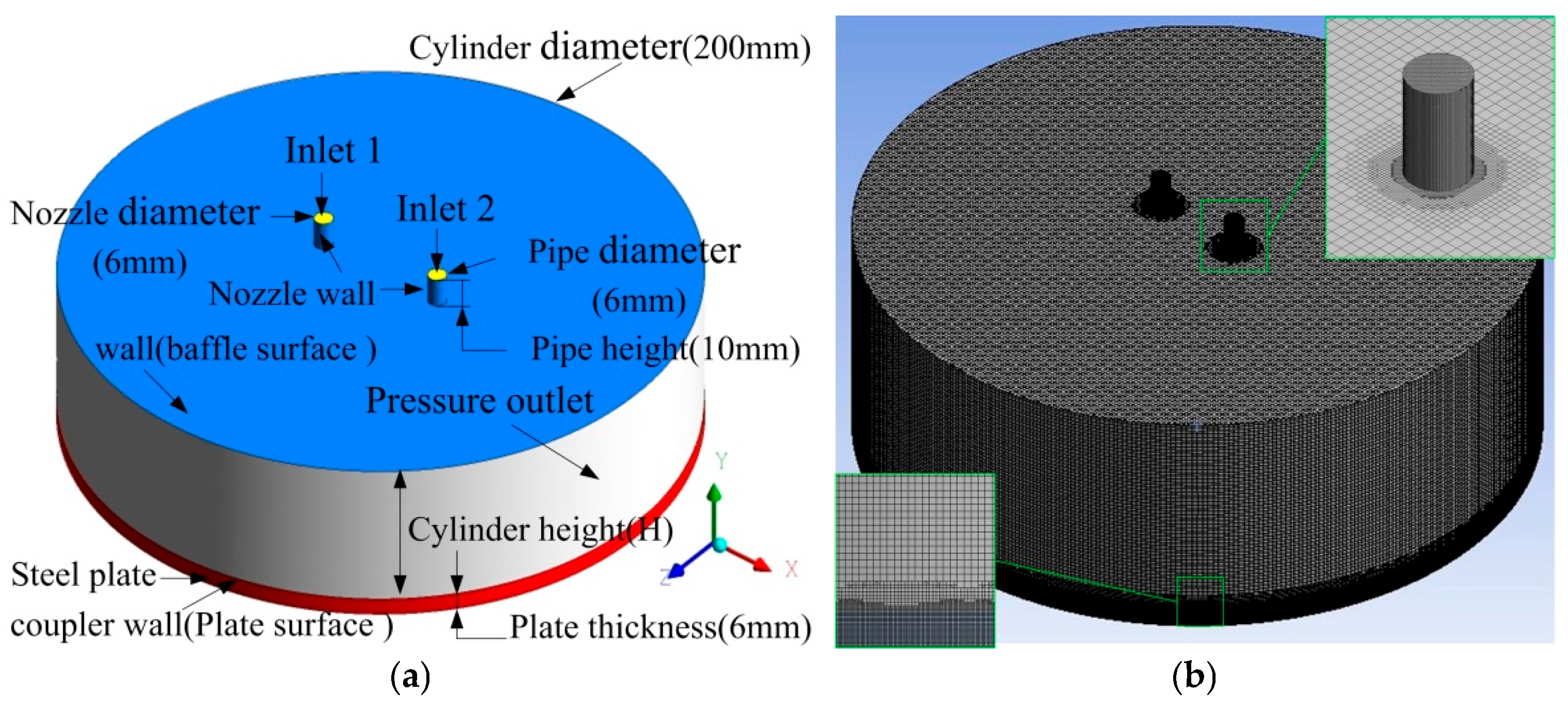
The three-dimensional computational domain for the impingement of twin vertical circular jets, along with the relevant boundary conditions for the numerical simulation, is depicted in Figure 2a. To precisely capture both the geometric symmetry and fluid dynamics characteristics of the vertically impinging twin circular jets, the 3D cylindrical computational domain was chosen. At the bottom of the model, the steel plate is represented by the red region, while the rest constitutes the fluid domain. There are two small cylinders positioned at the model’s apex, which serve as the nozzle pipes. The surrounding fluid in the computational model is regarded as ambient static air, while the impinging jet was composed of incompressible water. A uniform velocity and constant temperature were prescribed at the nozzle exit. The nozzle’s pipe has a diameter of d. The distance between the nozzle exit and the surface of the target heated plate is h. Space between twin nozzles is w. The non-dimensional distance from nozzle exit to steel plate surface is H (H = h/d) and the non-dimensional spacing between twin nozzles is W (W = w/d). The cylinder diameter of the fluid calculation region is 200 mm. The nozzle type is a straight-hole circular nozzle. The diameter of the nozzle is 6 mm and its length is 10 mm.

2.2. Governing Equations

The set of governing equations for steady, incompressible, Reynolds-averaged flow is composed of the continuity (Equation (1)), momentum (Equation (2)), and energy (Equation (3)) equations.
𝜕 u i 𝜕 x i   =   0
ρ u j 𝜕 u i 𝜕 x j   =   𝜕 P 𝜕 x i   +   𝜕 𝜕 x j μ 𝜕 u i 𝜕 x j   +   𝜕 u j 𝜕 x i     ρ u i u j ¯
ρ u j 𝜕 T 𝜕 x j   =   𝜕 𝜕 x j μ Pr 𝜕 T 𝜕 x j     ρ T u j ¯
Here, P and T represent the mean pressure and temperature, while T′, ui′, and uj′ denote their fluctuating components. The mean velocity components are ui and uj, and xi and xj are the coordinate directions. The fluid properties are density ρ, dynamic viscosity µ, and Prandtl number Pr. In the model, the Prandtl number (Pr) has a default value of 0.85.
In the numerical simulations, the eddy-viscosity model’s Realizable k-ɛ model is employed [33]. For the near-wall flow, the enhanced wall function is utilized. The interface between air and water is captured by means of the Volume of Fluid (VOF) approach. The Realizable k-epsilon model can be expressed as
𝜕 ρ k 𝜕 t   +   𝜕 ρ k u i 𝜕 x i   =   𝜕 𝜕 x j μ   +   μ t σ k 𝜕 k 𝜕 x j   +   G k     ρ ε
𝜕 ρ ε 𝜕 t   +   𝜕 ρ ε u i 𝜕 x i   =   𝜕 𝜕 x j μ   +   μ t σ ε 𝜕 ε 𝜕 x j   +   C 1 ρ E ε     C 2 ρ ε 2 k   +   ν ε
k is the turbulent energy, and ε is the turbulent dissipation rate. The default values for σk, σε, and C2 are 1.0, 1.2, and 1.9. The calculation formulas of other terms or coefficients are as follows:
C 1 = max 0.43 , η η + 5
η = 2 E i j E i j 1 / 2 k ε
E i j = 1 2 𝜕 u i 𝜕 x j + 𝜕 u j 𝜕 x i
μt and Cμ in Equation (5) are calculated as follows:
μ t = ρ C μ k 2 ε
C μ = 1 A o + A s U k / ε
Ao in Equation (10) is 4.377, and the calculation formulas for other unknown terms are as follows:
A s = 6 cos φ
φ = 1 3 cos 1 6 W
W = E i j E j k E k j E i j E i j
U = E i j E i j + Ω ˜ i j Ω ˜ i j
Ω ˜ i j = Ω i j 2 ε i j k ω k
Ω i j = Ω ¯ i j ε i j k ω k

2.3. Boundary Conditions

The starting medium of the fluid is stationary air, while an incompressible cooling water jet is employed. The incoming circular jet has a uniform velocity profile. The medium of inflow fluid is water (VFRC = 1), and the initial temperature is Tw (Tw = 298 K). The initial velocity of the jet is denoted by V. The computational domain was initialized with stationary air (species volume fraction VFRC = 0) at a uniform temperature of 300 K (Ta). A no-slip condition was applied at the wall boundaries, and the outlet was set to a zero normal pressure gradient. The steel plate was modeled as an isothermal wall with a uniform surface temperature of 1123 K (T0). In the numerical computation, the effect of phase-change heat was disregarded.

2.4. Numerical Considerations

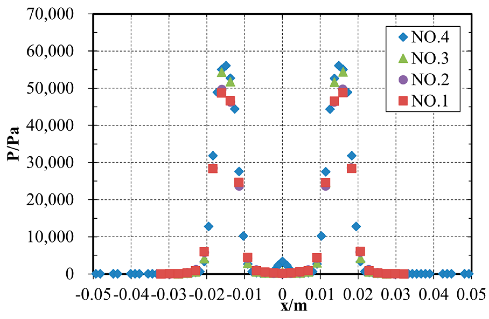
Hexahedral cells are employed to mesh the computational domain, presented in Figure 2b. To achieve a grid capable of resolving the boundary layer, the mesh is refined in the area where the free surface is anticipated. At the jet impingement zones (stagnation point and radial flow region) and the pipe (Figure 2), a fine mesh with a cell size of 0.1 mm was applied. In the two-phase region and the core flow field, a base cell size of 0.5 mm was used. Subsequently, the grid independence investigation needs to be conducted. A series of comparison tests were performed with a jet exit velocity of V = 10 m/s, the non-dimensional nozzle-to-plate distance of H = 10.8, the non-dimensional spacing between twin nozzles of W = 5, and cooling water temperature of Tw = 298 K. The results of the grid independence study for pressure at the steel plate surface are presented for different grids (Table 2) in Figure 3. It can be observed that grid independence is attained when the number of elements reaches 7.14306 × 10⁵. After this point, there is no further notable change in the pressure at the stagnation point.
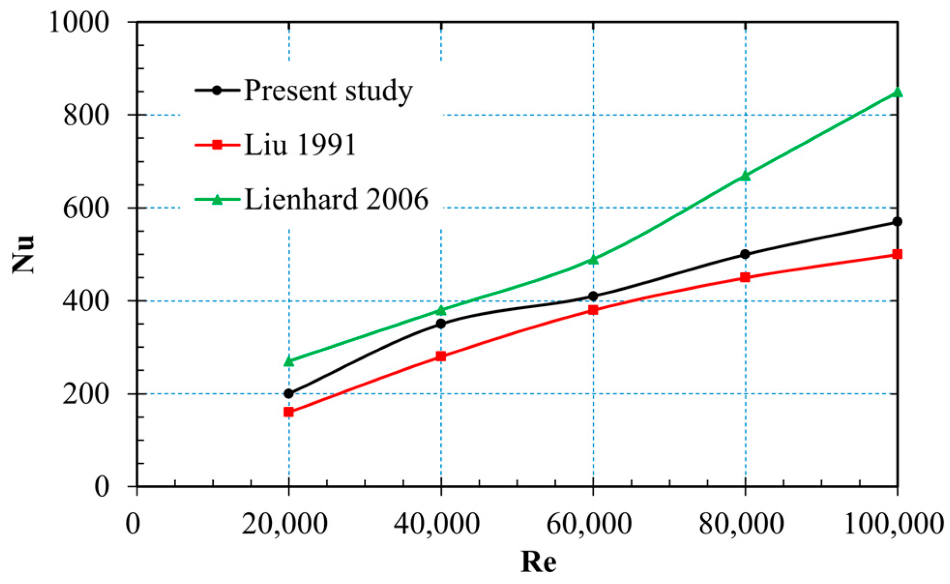
An in-depth investigation of mesh independence was carried out to establish the most suitable grid resolution. After that, extensive numerical simulations covering a variety of Reynolds numbers were performed. The validation of heat transfer carried out in this research is presented in Figure 4. This figure compares the Nusselt number at the stagnation point with the findings of Liu et al. [34] and Lienhard [35]. The simulated results of the Nusselt number at the stagnation point lie between those of Liu et al. [34] and Lienhard [35]. Based on these case results, it can be stated that the subsequent methodology has been validated. The governing equations with the considered boundary conditions were numerically solved by using the software ANSYS Fluent (2022 R2). For spatial discretization of equations related to momentum, volume fraction, turbulent kinetic energy, and turbulent dissipation rate, a first-order upwind scheme was adopted.

3. Results

This study primarily investigates the velocity field characteristics within the flow domain and corresponding Nusselt number distribution on steel plate surface. The computational analysis systematically examined the flow characteristics across the parametric range of jet velocity (V = 5 m/s, 7.5 m/s, 10 m/s), non-dimensional distance between nozzle exit and steel plate surface (H = 3.3, 5.8, 8.3, 10.8), and the non-dimensional spacing between twin nozzles (W = 5, 7.5, 10). The numerical results were analyzed upon reaching steady-state flow conditions. The simulations for each set of input parameters yielded the velocity field as well as the local and average Nusselt numbers. The local Nusselt number is defined based on the nozzle hydraulic diameter as the characteristic length. The specific formula used is
N u = h d k
h is the local convective heat transfer coefficient (W/m2·K). d is the hydraulic diameter of the nozzle (m), which serves as the characteristic length. k is the thermal conductivity of the fluid (water) at the film temperature (W/m·K). The convective heat transfer coefficient h was obtained from the simulated data using Newton’s law of cooling.

3.1. Velocity Distribution of the Flow Domains

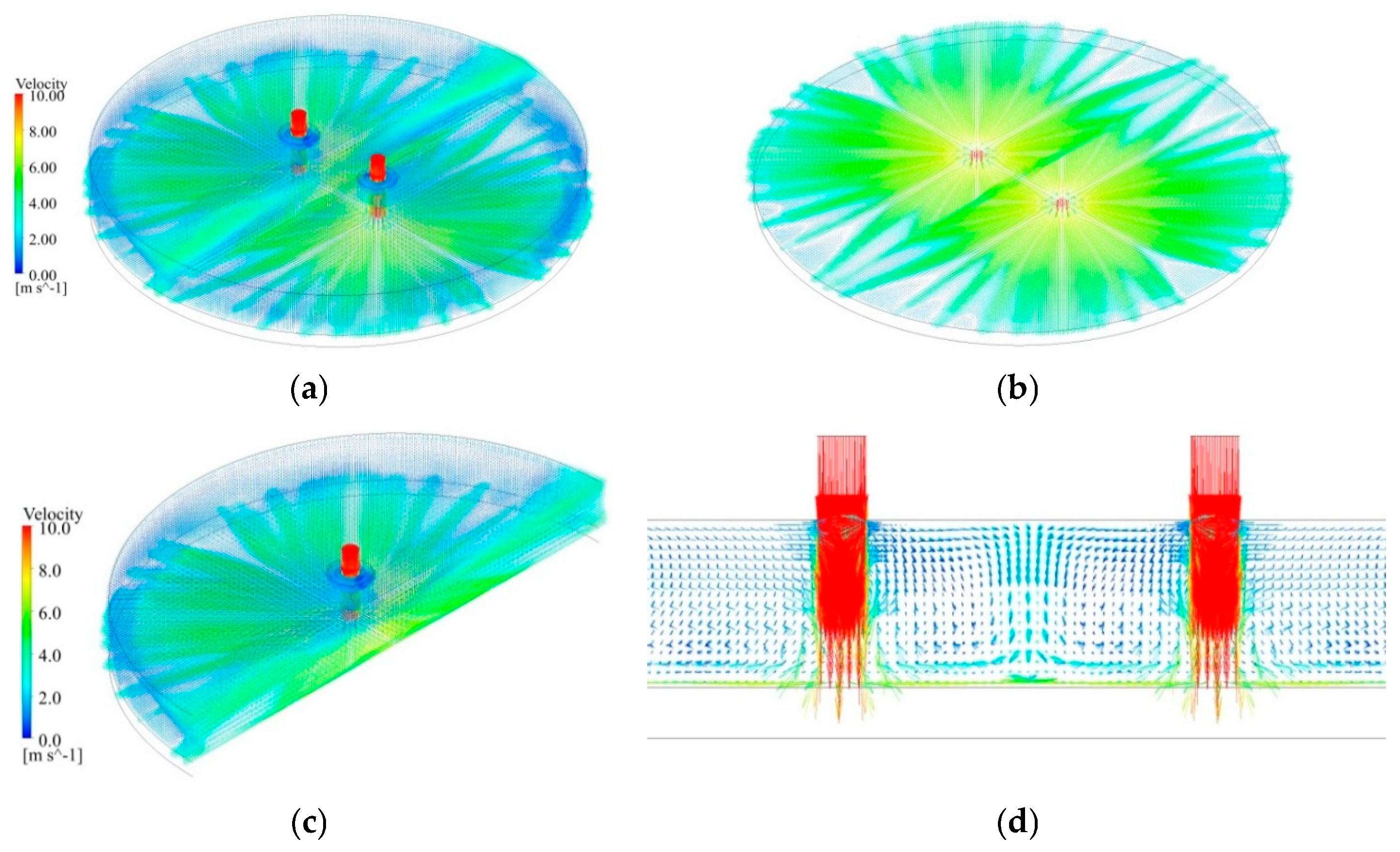
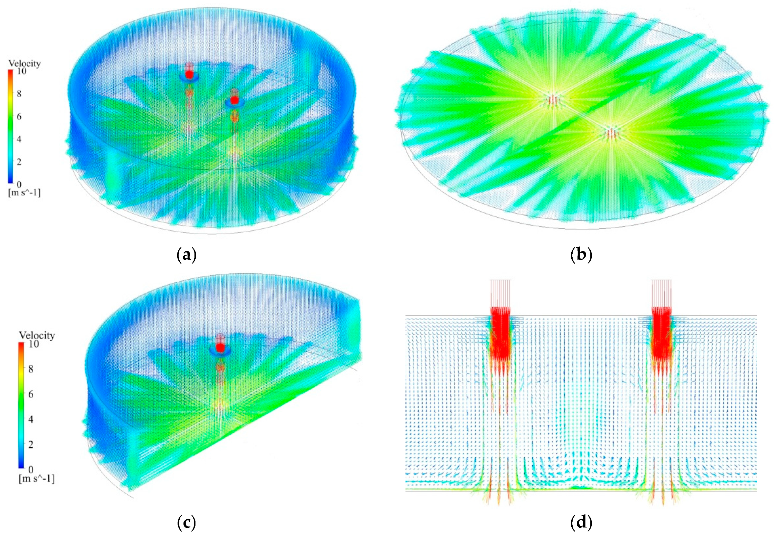
Figure 5 and Figure 6 show the velocity vector distribution for H = 3.3 and 8.3, W = 7.5, and V = 10 m/s. The velocity vector distribution of all flow domains is plotted in Figure 5a and Figure 6a, the section of paralleling the XZ plane and 0.0005 mm above the plate surface is plotted in Figure 5b and Figure 6b, the section of YZ plane is plotted in Figure 5c and Figure 6c, and the section of XY plane is plotted in Figure 5d and Figure 6d. It can be observed that the flow medium of the two jets impacts the steel plate surface at a high speed in the free-jet zone, and the variation trend of velocity attenuation and divergence for the twin jets are not obvious. Then, multiple water flows are formed in the wall-jet zone when jets impinge against the steel plate surface, the distance of them increases with the increase in plate surface radius, and the velocity decreases with the increase in jet radius. The wall-jet interaction zone appears in the middle of the two jets. The fountain upwash flow is a straight line, and it emerges as a vertical wall which takes an abrupt 90° turn [22]. Finally, the jet leaves the computational domain via its lateral side.

3.2. Local Nusselt Number Distribution

To investigate the thermal performance of circular-jet impingement cooling, the figures for various operating parameters and the spatial distributions of the local Nusselt number across the steel surface are depicted in Figure 7, Figure 8, Figure 9, Figure 10, Figure 11 and Figure 12. The local Nusselt number distribution was obtained over a surface length of 200 mm. The local Nusselt number profile along the X-axis exhibits, as observed in prior studies [14,25,36].
As shown in Figure 7, Figure 8 and Figure 9, the general trend of Nu along the X-axis is like two volcanoes; the two craters appear at the jet impingement zone. The distribution of the Nusselt number presents a distinct pattern: there is a local minimum at the stagnation point, then a sudden peak occurs, followed by a swift decline in the near-wall area. Finally, for locations far from the jets, it shows a slight decrease with the distance. A lower Nusselt number is observed at the jet stagnation point compared to the crater rim. As the distance between twin nozzles grows, the interaction between the two jets weakens. This finding verifies that when the gap between the jets is extremely large, the interaction between the two jets can be disregarded. This distribution is a direct signature of the fountain upwash flow. The collision of the two wall jets generates a upward-moving fountain flow. The lowest Nu at the exact center implies that this fountain, at its root, may have a stagnation or lower velocity core that is less effective at scrubbing the thermal boundary layer. This pattern fundamentally demonstrates that the cooling effect in the interstitial zone is not dictated by a single jet but is a result of this complex, jet-induced secondary flow.
While the stagnation point experiences the highest pressure and the thinnest hydrodynamic boundary layer, the intense impingement force at this point suppresses bubble nucleation and growth. Heat transfer is dominated by single-phase forced convection, which, despite being strong, is less effective than the combined convection and nucleation at the peak location. This leads to a relative local minimum in the Nu. As the flow accelerates radially outward, the wall pressure and the impingement force drop rapidly. This sudden pressure reduction creates conditions highly favorable for violent bubble nucleation and growth. This synergy creates the sharp peak in the Nusselt number. Further downstream, the continuous growth of the hydrodynamic and thermal boundary layers reduces the temperature gradient and leads to a rapid decline in the Nu.
As the jet velocity rises, the Nu increases in the jet impingement zone, while in the wall-jet zone, it shows no significant change. Neither the non-dimensional nozzle-to-plate distance (H) nor the non-dimensional spacing between twin nozzles (W) exerts an obvious influence on it. Therefore, the velocity of the nozzle exit is the primary factor influencing the intensity of jet impingement in the jet impingement area, yet it has no notable impact on the wall-jet area. Analysis of Figure 7, Figure 8, Figure 9, Figure 10, Figure 11 and Figure 12reveals a secondary influence of the nozzle-to-surface distance and nozzle spacing on heat transfer intensity, with jet velocity emerging as the predominant factor. In future work developments, other distances between the nozzle and the plate surface, as well as the distances among nozzles, will be taken into account.
In the impingement zone, as the jet velocity increases, the stagnation pressure rises significantly, resulting in a much thinner hydrodynamic and thermal boundary layer at and near the stagnation point. Since the heat transfer rate is inversely proportional to the boundary layer thickness, this leads to a substantial increase in the Nusselt number. In the wall-jet zone, the flow is primarily shear-driven and its development is less sensitive to the initial jet velocity in the same way. The wall jet has already turned and is developing along the surface. While a higher inlet velocity does increase the local Reynolds number, it also causes the wall jet to entrain more fluid and grow thicker, leading to a net change in the local Nusselt number that is much smaller than in the impingement zone.
The general tendency of the Nu along the Z-axis (the path of fountain upwash flow) is presented in Figure 10 through Figure 12. The Nu of the interaction line of two jets decreases with the increase in the non-dimensional spacing between twin nozzles (W), but the thermal interaction length for W = 5 is shorter than the other two cases (W = 7.5 and 10). In a specific range, enlarging the distance between the centers of nozzles can enhance the thermal interaction zone between the twin jets. Analogous to the outcomes regarding the X-axis mentioned earlier, the Nusselt number value along the interaction line of the two jets also rises as the jet velocity increases. The Nusselt number’s valley value shows up at the midpoint of the interaction line, while its peak value is close to the mid-region of the interaction line. Based on the outcomes of the X-axis and Z-axis, it can be deduced that in the center of the two jets, there exists a region with low heat transfer intensity.
Quantitative analysis of the local Nusselt number distribution in Figure 7, Figure 8 and Figure 9 reveals that the configuration with the non-dimensional spacing between twin nozzles W = 5 demonstrates enhanced cooling uniformity across the central plate region (x = −0.05 m to 0.05 m), compared to the larger spacings of W = 7.5 and W = 10. Cooling uniformity within this region is also enhanced with increasing jet velocity. This enhanced heat transfer in the central region can be attributed to the stronger fountain upwash flow generated by the closer proximity of the two impinging jets. The coalescence of their wall jets results in a more concentrated and vigorous upward flow, which subsequently impinges on the plate, elevating the local Nusselt number. The higher momentum promotes greater flow mixing and stabilizes the fountain, which leads to a more homogeneous heat transfer distribution.

3.3. Average Nusselt Number Variation Along the Steel Surface

Figure 13, Figure 14 and Figure 15 show the average Nusselt number (NuA) variation in the steel plate surface for various parameters. NuA along the X-axis and Z-axis within ±0.1 m are plotted in Figure 13 and Figure 14 and the NuA within ±0.05 m in Figure 15. The analysis reveals that the surface-averaged Nusselt number exhibits a strong positive correlation with jet velocity, while demonstrating minor oscillations with nozzle-to-plate spacing. In the parameter scope of this paper, the peak heat transfer performance occurs at the non-dimensional nozzle-to-plate distance (H) of 5.8. When the nozzle is sufficiently close to the surface yet the jet’s potential core remains intact, a high impingement velocity is ensured. However, the confined space restricts the development of the radial wall jet. When the nozzle is far from the surface, the jet’s potential core has dissipated due to vigorous mixing with the surrounding quiescent fluid. Consequently, the time-average velocity decays significantly before the jet reaches the surface. The impingement velocity is lower, and while the turbulence is high, it cannot compensate for the loss of momentum, resulting in a decline in heat transfer intensity. When the non-dimensional distance between twin nozzles increases from 5 to 10 within a range of ±0.1 m, the change in the average Nusselt number is not very evident. In the wall-jet interaction zone, specifically in the middle of two jets, as non-dimensional spacing between twin nozzles (W) rises from 5 to 7.5, the average Nusselt number increases. Then, when W increases from 7.5 to 10 within the ±0.1 m range, it drops slightly. However, when considering a range of ±0.05 m and W increasing from 5 to 10, particularly at a jet velocity of 10 m/s, the average Nusselt number gradually decreases.

3.4. Nusselt Number at Stagnation Point

The distribution of the stagnation-point Nusselt number (Nus) across the parameter space under investigation is shown in Figure 16. The Nus shows a positive correlation with the distance between the nozzle and the plate. The Nus increases by about 9–30% with the increase in the non-dimensional nozzle-to-plate distance for V = 5 m/s, and it increases by about 4–23% for V = 10 m/s. For W = 7.5, the Nus increases significantly as the non-dimensional nozzle-to-plate distance increases from 3.3 to 10.8. For W = 5, a rise in jet velocity from 5 m/s to 10 m/s yields a 66–82% increase in the stagnation-point Nusselt number. Based on the analysis outcome of the Nus, within a specific range, appropriately increasing the distances between the nozzle and steel surface can enhance the heat transfer intensity of the stagnation zone. As the non-dimensional nozzle-to-plate distance(H) increases, the jet has a longer travel distance to entrain the surrounding fluid. This promotes the development of a turbulent mixing layer at the jet periphery. When this jet with a higher level of turbulence impinges on the surface, the intensified fluid mixing significantly thins the thermal boundary layer, thereby augmenting the convective heat transfer coefficient. Within this specific H range, the enhancement of heat transfer by increased turbulent mixing serves as the dominant mechanism, overriding the marginal decay of the centerline velocity and resulting in a net increase in the Nusselt number.

3.5. Peak Value of Nusselt Number

To delve deeper into the influence of the non-dimensional nozzle-to-plate distance (H) and non-dimensional spacing between twin nozzles (W) on the jet impingement zone, the peak values of Nusselt number (NuP) distribution along the X-axis and Z-axis are presented in Figure 17 and Figure 18. The peak value of the Nusselt number increases significantly with the increasing of the non-dimensional nozzle-to-plate distance for the X-axis, and the big peak of the Nusselt number can be observed for H = 10.8. The gap of the NuP increases with the increasing of the jet velocity for different non-dimensional spacings between twin nozzles (W). Conversely, the NuP along the Z-axis decreases as the non-dimensional nozzle spacing increases. However, the highest overall peak value is observed at W = 5. The heat transfer intensity of the wall-jet interaction zone can be changed slightly by decreasing the nozzle-to-nozzle spacing.
At smaller H, the two jets and their radial wall jets interact intensely and immediately after impingement. This close-proximity interaction can lead to destructive interference, thereby thinning the effective cooling coverage and limiting the peak heat transfer potential. As H increases, the jets have more space to develop independently before their wall jets collide. This delay in interaction allows the individual jets to establish stronger, more stable stagnation regions. The subsequent collision at a greater distance from the wall then forms a more vigorous and organized fountain flow that constructively enhances fluid mixing and scouring of the surface between the jets, leading to a significantly higher peak Nusselt number.
At a low jet velocity, the jets have lower momentum and are more susceptible to mutual interference and dissipation. The difference in the flow field and heat transfer performance between different W values is, thus, less pronounced. However, at a high jet velocity, the jets possess higher inertia and can sustain their individual structure over a longer distance. The difference in the interaction efficiency between various W values becomes amplified at high velocity.

4. Discussion

The present numerical investigation elucidates the complex fluid dynamics and concomitant heat transfer behavior inherent in twin-jet impingement cooling on a heated steel plate. Our findings, particularly regarding the formation of the fountain upwash flow and the resultant Nusselt number (Nu) distributions, align with and extend the current understanding of multi-jet impingement systems.
The observed flow morphology, characterized by the generation of multiple wall jets and the development of a distinct, linear fountain upwash between the two impingement points, is a canonical feature of interacting jets. This upwash fountain, a direct consequence of the collision between the opposing wall jets, creates a secondary stagnation region that significantly influences the local thermal field. The relationship between the NuA and system parameters reveals further nuances. The slight fluctuation of the NuA with the non-dimensional nozzle-to-plate distance, H, and identified optimum at H = 5.8 are critical for industrial system design. The subsequent gradual decline in average Nu with increasing W from 5 to 10 underscores a fundamental scaling in multi-jet systems: as the jet density decreases, the overall heat transfer capability diminishes, despite the local enhancements in the interaction regions. The enhancement of stagnation zone’s heat transfer by optimizing H/d is directly linked to the integrity of jet core. Conversely, sensitivity of the wall-jet interaction zone to W highlights that this region is governed by the interplay of two developed wall jets, a dynamic distinct from the primary impingement process.
The present numerical model, while capturing the essential physics of twin-jet interaction, incorporates several simplifying assumptions. Firstly, the boiling heat transfer mechanism was neglected, and an isothermal wall boundary condition was adopted. It does not capture the transient temperature drop and the complex boiling regimes prevalent in actual ultra-fast cooling processes. Secondly, the influence of cross-flow, which is significant in multi-jet industrial systems and drastically alters the impingement dynamics, was not considered in this idealized twin-jet configuration.
The implications of this work extend directly to the design of high-strength cooling systems in steel processing. The results provide a quantitative basis for selecting H and W to either maximize cooling intensity in critical areas or to achieve a more uniform thermal profile across the plate surface. However, this study focused on a twin-jet configuration. In industrial applications, arrays of dozens or hundreds of jets are employed. Future research should, therefore, transition from the idealized twin-jet system to investigate full-scale nozzle arrays. Specifically, the interaction between the fountain upwash flows and the cross-flow, and its impact on the global Nu distribution, warrants detailed investigation.

5. Conclusions

A systematic numerical investigation of turbulent twin-jet impingement cooling on heated steel plates was conducted to evaluate the influence of three critical parameters: (1) nozzle exit jet velocity (V), (2) the non-dimensional nozzle-to-plate distance (H), and (3) the non-dimensional spacing between twin nozzles (W) on the resulting Nusselt number distribution. The main findings are presented below:
(1)
When the jets strike the surface of the steel plate, several water flows are generated in the wall-jet area, and the distance between them grows as the radius of the plate surface increases. Between the two jets, there emerges an area of wall-jet interaction, and the fountain upwash flow presents as a straight line.
(2)
In the parallel direction of the two jets’ centerline, the local Nusselt number exhibits a characteristic profile, beginning with a minimum at the stagnation point, rapidly increasing to a peak value, and subsequently decaying sharply with radial distance from the impingement zone. Finally, it shows a slight decline as the distance increases. While in vertical direction, the Nusselt number of the interaction line of the two jets decreases with increasing non-dimensional spacing between twin nozzles (W), However, the thermal interaction length for W = 5 is shorter than the other two cases (W = 7.5 and 10).
(3)
The NuA of the plate surface fluctuates slightly with the distance from the nozzle to the plate surface, and the maximum value of NuA is obtained when the non-dimensional nozzle-to-plate distance (H) is 5.8. Meanwhile, due to the limitations within ±0.05 m, it shows a gradual decline as the non-dimensional distance between twin nozzles (W) increases from 5 to 10.
(4)
The heat transfer intensity of stagnation zone can be enhanced by appropriately increasing the distance of the nozzle-to-plate surface within a certain range, and the heat transfer intensity of the wall-jet interaction zone can be changed slightly by decreasing the nozzle-to-nozzle spacing.

6. Future Direction

Based on the findings and limitations of this study, several key directions for future research are proposed:
(1)
The current work focused on a limited set of parameters. Future investigations should explore a wider parametric space, including a broader range of Reynolds numbers, nozzle-to-plate distances, and nozzle spacings. Furthermore, research should extend to more complex nozzle arrangements, such as jet arrays, and the use of inclined or swirling jets, which could offer superior control over cooling uniformity and heat transfer distribution on large-scale surfaces.
(2)
In this work, a constant isothermal wall condition and Realizable k-ε model were selected, the effect of phase change heat was disregarded, and the influence of the transient temperature drop of the high-temperature steel plate was not thoroughly investigated. Developing a completely transient-coupled model that includes a complete boiling curve is the key to future work. The application of more sophisticated numerical models is critical to unravel the underlying physics. Exploring the application of more advanced turbulence and multiphase models (e.g., RSM or LES) to capture finer flow dynamics is also critical.

Author Contributions

Conceptualization, J.S. and X.J.; methodology, J.S. and F.H.; software, J.S. and Z.Z.; validation, J.S., F.H., J.Y. and X.J.; formal analysis, J.S. and X.J.; investigation, J.S., F.H. and J.Y.; resources, J.S. and X.J.; data curation, J.S. and Z.Z.; writing—original draft preparation, J.S. and J.Y.; writing—review and editing, J.S. and Z.Z.; visualization, J.S. and F.H.; supervision, J.S. and X.J.; project administration, J.S., X.J. and J.Y.; funding acquisition, J.S. All authors have read and agreed to the published version of the manuscript.

Funding

This research was funded by the Shandong Provincial Natural Science Foundation of China (Grant NO. ZR2022ME082).

Data Availability Statement

The original contributions presented in this study are included in the article. Further inquiries can be directed to the corresponding author.

Conflicts of Interest

The authors declare no conflicts of interest.

Abbreviations

The following abbreviations are used in this manuscript:
dnozzle diameter (0.006 m)
hdistance between nozzle exit and target heated plate surface (mm)
Hnon-dimensional nozzle-to-plate distance (-)
NuNusselt number (-)
NuAaverage Nusselt number (-)
NuSNusselt number at stagnation point (-)
NuPpeak value of Nusselt number (-)
Twinitial temperature of water (298 K)
Tainitial temperature of air (300 K)
T0initial temperature of steel plate (1123 K)
Vthe jet velocity at the nozzle exit (m/s)
wspacing between twin nozzles (mm)
Wthe non-dimensional spacing between twin nozzles (-)

References

  1. Gomez, C.F.; Geld, C.W.M.; Kuerten, J.G.M.; Bsibsi, M.; Esch, B.P.M. Quench cooling of fast moving steel plates by water jet impingement. Int. J. Heat Mass Transf. 2020, 163, 120545. [Google Scholar] [CrossRef]
  2. Li, X.Q.; Xia, W.H.; Yang, K.; Dai, L.F.; Wang, F.; Xie, Q.; Cai, J.J. Quench cooling of steel plates by reciprocating moving water jet impingement. Exp. Therm. Fluid Sci. 2024, 153, 111127. [Google Scholar] [CrossRef]
  3. Suresh, B.G.; Gaurav, A.K.; Stephan, R.; Eckehard, S. Heat transfer analysis during quenching of moving metal plates using water jets from a mold. Therm. Sci. Eng. Prog. 2025, 64, 103792. [Google Scholar] [CrossRef]
  4. Xu, R.; Zhang, R.Y.; Jiang, J.Y.; Wang, Z.B.; Zhang, Z.; Zheng, K.L.; Zhao, L. Investigation on the jet impingement cooling of steel discs using air-atomized water mist. Int. J. Heat Mass Transf. 2025, 245, 126989. [Google Scholar] [CrossRef]
  5. Wang, S.J.; Lin, Q.G.; Li, T.; Tan, M.Y.; Shi, Z.H.; Liu, H.F.; Li, W.F. Study on flow and heat transfer characteristics of cross-jet impingement cooling. Int. J. Heat Mass Transf. 2026, 255, 127772. [Google Scholar] [CrossRef]
  6. Dou, R.; Wen, Z.; Zhou, G.; Liu, X.; Feng, X. Experimental study on heat-transfer characteristics of circular water jet impinging on high-temperature stainless steel plate. Appl. Therm. Eng. 2014, 62, 738–746. [Google Scholar] [CrossRef]
  7. Guo, Q.; Wen, Z.; Dou, R. Experimental and numerical study on the transient heat-transfer characteristics of circular air-jet impingement on a flat plate. Int. J. Heat Mass Transf. 2017, 104, 1177–1188. [Google Scholar] [CrossRef]
  8. Avadhesh, K.S.; Santosh, K.S. An experimental study on heat transfer and rewetting behavior of hot horizontal downward facing hot surface by mist jet impingement. Appl. Therm. Eng. 2019, 151, 459–474. [Google Scholar] [CrossRef]
  9. Wang, C.; Wang, X.; Shi, W.; Lu, W.; Tan, S.K.; Zhou, L. Experimental investigation on impingement of a submerged circular water jet at varying impinging angles and Reynolds numbers. Exp. Therm. Fluid Sci. 2017, 89, 189–198. [Google Scholar] [CrossRef]
  10. Colucci, D.W.; Viskanta, R. Effect of nozzle geometry on local convective heat transfer to a confined impinging air jet. Exp. Therm. Fluid Sci. 1996, 13, 71–80. [Google Scholar] [CrossRef]
  11. Ibroheng, P.; Anil, K.; Natthaporn, K.; Chayut, N. Flow and heat transfer characteristics of submerged impinging air-water jets. Int. J. Therm. Sci. 2023, 193, 108503. [Google Scholar] [CrossRef]
  12. Wang, X.L.; Motala, D.; Lu, T.J.; Song, S.J.; Kimb, T. Heat transfer of a circular impinging jet on a circular cylinder in crossflow. Int. J. Therm. Sci. 2014, 78, 1–8. [Google Scholar] [CrossRef]
  13. Hadipour, A.; Zargarabadi, M.R. Heat transfer and flow characteristics of impinging jet on a concave surface at small nozzle to surface distances. Appl. Therm. Eng. 2018, 138, 534–541. [Google Scholar] [CrossRef]
  14. Joo, H.M.; Soyeong, L.; Jungho, L.; Seong, H.L. Numerical study on subcooled water jet impingement cooling on superheated surfaces. Case Stud. Therm. Eng. 2022, 32, 101883. [Google Scholar] [CrossRef]
  15. Chee, M.W.L.; Chauhan, P.; Georgiou, J.; Wilson, D.I. Flow distribution in the liquid film created by a coherent circular water jet impinging obliquely on a plane wall. Exp. Therm. Fluid Sci. 2023, 140, 110748. [Google Scholar] [CrossRef]
  16. Taghinia, J.; Rahman, M.M.; Siikonen, T. Numerical investigation of twin-jet impingement with hybrid-type turbulence modeling. Appl. Therm. Eng. 2014, 73, 650–659. [Google Scholar] [CrossRef]
  17. Sandoval, C.; Treviño, C.; Alvarez, A.; Matuz, D.; Lizardi, J.; Martínez-Suástegui, L. Flow field analysis of submerged oblique and normally impinging twin jets at varying impinging angles. Exp. Therm. Fluid Sci. 2025, 167, 111491. [Google Scholar] [CrossRef]
  18. Greco, C.S.; Castrillo, G.; Crispo, C.M.; Astarita, T.; Cardone, G. Investigation of impinging single and twin circular synthetic jets flow field. Exp. Therm. Fluid Sci. 2016, 74, 354–367. [Google Scholar] [CrossRef]
  19. Ozmen, Y. Confined impinging twin air jets at high Reynolds numbers. Exp. Therm. Fluid Sci. 2011, 35, 355–363. [Google Scholar] [CrossRef]
  20. Singh, D.; Premachandran, B.; Kohli, S. Double circular air jet impingement cooling of a heated circular cylinder. Int. J. Heat Mass Transf. 2017, 109, 619–646. [Google Scholar] [CrossRef]
  21. Yin, Z.; Zhang, H.; Lin, J. Experimental study on the flow field characteristics in the mixing region of twin jets. J. Hydrodyn. 2007, 19, 309–313. [Google Scholar] [CrossRef]
  22. Meslem, A.; Sobolik, V.; Bode, F.; Sodjavi, K.; Zaouali, Y.; Nastase, I.; Croitoru, C. Flow dynamics and mass transfer in impinging circular jet at low Reynolds number. Comparison of convergent and orifice nozzles. Int. J. Heat Mass Transf. 2013, 67, 25–45. [Google Scholar] [CrossRef]
  23. Nakabe, K.; Fornalik, E.; Eschenbacher, J.F.; Yamamoto, Y.; Ohta, T.; Suzuki, K. Interactions of longitudinal vortices generated by twin inclined jets and enhancement of impingement heat transfer. Int. J. Heat Fluid Flow 2001, 22, 287–292. [Google Scholar] [CrossRef]
  24. Kate, R.P.; Das, P.K.; Chakraborty, S. An experimental investigation on the interaction of hydraulic jumps formed by two normal impinging circular liquid jets. J. Fluid Mech. 2007, 590, 355–380. [Google Scholar] [CrossRef]
  25. Teamah, M.A.; Khairat, M.M. Heat transfer due to impinging double free circular jets. Alex. Eng. J. 2015, 54, 281–293. [Google Scholar] [CrossRef]
  26. Thibaut, J.; Ivana, V.; Serge, S. Flow dynamics, heat and mass transfer of laminar, round twin-jet impinging a uniformly heated flat plate. Int. J. Heat Mass Transf. 2025, 236, 126187. [Google Scholar]
  27. Abraham, S.; Vedula, R.P. Effectiveness distribution measurements for a row of heated circular jets impinging on a cylindrical convex surface at different inclinations. Int. J. Heat Fluid Flow 2018, 69, 210–223. [Google Scholar] [CrossRef]
  28. Dong, L.L.; Leung, C.W.; Cheung, C.S. Heat transfer of a row of three butane/air flame jets impinging on a flat plate. Int. J. Heat Mass Transf. 2003, 46, 113–125. [Google Scholar] [CrossRef]
  29. Chiu, H.; Jang, J.; Yan, W. Experimental study on the heat transfer under impinging elliptic jet array along a film hole surface using liquid crystal thermograph. Int. J. Heat Mass Transf. 2009, 52, 4435–4448. [Google Scholar] [CrossRef]
  30. Caliskan, S.; Baskaya, S.; Calisir, T. Experimental and numerical investigation of geometry effects on multiple impinging air jets. Int. J. Heat Mass Transf. 2014, 75, 685–703. [Google Scholar] [CrossRef]
  31. Geers, L.F.G.M.; Tummers, J.; Hanjalić, K. Experimental investigation of impinging jet arrays. Exp. Fluids 2004, 36, 946–958. [Google Scholar] [CrossRef]
  32. Mohammad, J.; Bahram, M. Quenching a rotary hollow cylinder by multiple configurations of water-impinging jets. Int. J. Heat Mass Transf. 2019, 137, 124–137. [Google Scholar] [CrossRef]
  33. Hosain, M.L.; Fdhila, R.B.; Daneryd, A. Heat transfer by liquid jets impinging on a hot flat surface. Appl. Energy 2016, 164, 934–943. [Google Scholar] [CrossRef]
  34. Liu, X.; Lienhard, V.J.H.; Lombara, J.S. Convective heat transfer by impingement of circular liquid jets. J. Heat Transf. 1991, 113, 571–582. [Google Scholar] [CrossRef]
  35. Lienhard, V.J.H. Heat transfer by impingement of circular free-surface liquid jets. In Proceedings of the 18th National & 7th ISHMT-ASME Heat and Mass Transfer Conference, Guwahati, India, 4–6 January 2006; pp. 1–16. [Google Scholar]
  36. Li, C.; Shi, Y.N.; Yang, H.; Zhang, Y.S.; Yuan, G.; Li, Z.L.; Zhang, F.B. Heat transfer characteristics of water jet impingement on high-temperature steel plate by angular nozzle. Int. Commun. Heat Transf. 2024, 151, 107243. [Google Scholar] [CrossRef]
Figure 1. UFC equipment of hot-rolled strip (a) and the circular cooling nozzle (b).
Metals 15 01305 g001
Figure 2. Three-dimensional (a) dimensions and boundary conditions and (b) mesh.
Metals 15 01305 g002
Figure 3. Results of grid independence study for pressure at the impingement surface.
Metals 15 01305 g003
Figure 4. Nusselt number at stagnation point for different Re [34,35].
Metals 15 01305 g004
Figure 5. Velocity vector distribution for H = 3.3 (a), (b) parallel to XZ plane for y = 0.0065 m, (c) YZ plane, and (d) XY plane.
Metals 15 01305 g005
Figure 6. Velocity vector distribution in flow domain for H = 8.3 (a), (b) XZ plane for y = 0.0065 m, (c) YZ plane, and (d) XY plane.
Metals 15 01305 g006
Figure 7. Nusselt number along the X-axis at V = 5 m/s.
Metals 15 01305 g007
Figure 8. Nusselt number along the X-axis at V = 7.5 m/s.
Metals 15 01305 g008
Figure 9. Nusselt number along the X-axis at V = 10 m/s.
Metals 15 01305 g009
Figure 10. Nusselt number along the Z-axis at V = 5 m/s.
Metals 15 01305 g010
Figure 11. Nusselt number along the Z-axis at V = 7.5 m/s.
Metals 15 01305 g011
Figure 12. Nusselt number along the Z-axis at V = 10 m/s.
Metals 15 01305 g012
Figure 13. NuA along X-axis within ±0.1 m.
Metals 15 01305 g013
Figure 14. NuA along Z-axis within ±0.1 m.
Metals 15 01305 g014
Figure 15. NuA along Z-axis within ±0.05 mm.
Metals 15 01305 g015
Figure 16. Nus of x axil for 5 m/s (a) and 10 m/s (b).
Metals 15 01305 g016
Figure 17. The peak value of Nusselt number variation in the X-axis: (a) 5 m/s and (b) 10 m/s.
Metals 15 01305 g017
Figure 18. The peak value of Nusselt number variation in the Z-axis: (a) 5 m/s and (b) 10 m/s.
Metals 15 01305 g018
Table 1. Connection between water flow rate and jet speed of the circular nozzle.
Water Flow/(m3/s)0.013890.016670.019440.022220.03889
V/(m/s), d = 0.045 m6.859.1311.4213.7015.98
V/(m/s), d = 0.006 m3.855.146.427.718.99
Table 2. The number of nodes and elements.
GridNodesElements
NO.1295,215259,788
NO.2675,922588,724
NO.3800,104714,306
NO.41,247,1531,103,653
Disclaimer/Publisher’s Note: The statements, opinions and data contained in all publications are solely those of the individual author(s) and contributor(s) and not of MDPI and/or the editor(s). MDPI and/or the editor(s) disclaim responsibility for any injury to people or property resulting from any ideas, methods, instructions or products referred to in the content.