Abstract
The processing of bulk amorphous alloys is typically realized through superplastic deformation in the supercooled liquid region, and current research efforts predominantly focus on enhancing formability by optimizing processing parameters such as temperature and duration. However, excessive temperatures or prolonged exposure times can induce crystallization, which severely compromises the mechanical and functional properties of the alloy. This study presents the design of an ultrasonic vibration (UV)-assisted metal hot-forming apparatus that integrates an ultrasonic vibration field into the superplastic flow deformation of amorphous alloys. High-temperature compression experiments were conducted on Zr55Cu30Al10Ni5 amorphous alloy, and finite element simulations were performed to model the experimental process. Results show that ultrasonic vibration reduces the flow stress of the amorphous alloy, thereby enhancing its superplastic deformation capability. Simulation analysis reveals that surface effects arise from periodic interface separation between the pressure plate and the specimen caused by ultrasonic vibration, leading to a cyclic disappearance of friction forces, which manifest macroscopically as a reduction in effective friction. On the other hand, vibration introduces additional strain rates. Since the undercooled liquid of amorphous alloys exhibits non-Newtonian fluid behavior characterized by shear-thinning, ultrasonic vibration assistance can effectively reduce the apparent viscosity, thereby improving their filling capacity.
1. Introduction
Amorphous alloys exhibit long-range disorder and short-range order in three-dimensional space due to the insufficient time for atomic rearrangement during rapid solidification of the liquid metal [1]. Owing to their metastable structure, these alloys demonstrate exceptional properties such as high strength, high hardness, excellent corrosion and wear resistance, and superior soft magnetic characteristics, making them highly attractive for diverse applications. As a result, they are widely regarded as promising advanced structural and functional materials. With continuous advancements in fabrication technologies, representative systems—including Zr-based, Fe-based, Pd-based, and Ti-based alloys—have progressively achieved commercialization. For instance, the Zr-based amorphous alloy surgical scissors developed by Liquidmetal Technologies (Lake Forest, CA, USA) offer a service life exceeding five times that of conventional stainless-steel instruments, while also significantly reducing postoperative infection rates [2]. Fe-based amorphous alloys, characterized by high magnetic permeability and low core loss, have been employed as soft magnetic materials to replace silicon steel in transformers, achieving up to a 30% reduction in no-load losses [3]. Furthermore, amorphous alloy motors show great potential in new energy vehicles, enabling high torque output at low starting currents, maintaining stable torque at high speeds, and improving energy efficiency under high-speed operation. Additionally, Zeiss (Oberkochen, Germany) utilizes Pd-based amorphous alloys in the fabrication of X-ray lens mounts, markedly enhancing imaging stability under high-energy radiation conditions [4].
Bulk amorphous alloys exhibit high strength and hardness at room temperature, making them highly resistant to conventional mechanical machining. However, upon heating to the supercooled liquid region, their viscosity decreases dramatically, enabling pronounced superplastic behavior. Leveraging this low-viscosity flow capability allows for highly precise near-net-shape forming, offering a promising solution for the fabrication of micro-scale components in advanced technological fields such as biomedical devices, aerospace systems, and micro-electromechanical systems (MEMS) [5,6,7,8]. Savaedi et al. [9] reviewed research on the superplastic forming of amorphous alloys and found that the strain rate sensitivity coefficient approaches unity (m ≈ 1) in the supercooled liquid region, indicating Newtonian flow behavior during thermal forming. While increasing temperature reduces viscosity and enhances formability, excessively high temperatures risk inducing crystallization. Liu et al. [10] systematically investigated the rheological behavior of two amorphous alloys, Zr61Cu25Al12Ti2 and Zr52.5Cu17.9Ni14.6Al10Ti5, under uniaxial compression in the supercooled liquid region by using a thermomechanical simulator and established the boundary conditions for the transition from Newtonian to non-Newtonian flow, as well as constructed deformation maps accordingly. Yang et al. [11] studied the rheological behavior of the high-entropy amorphous alloy Ti20Zr20Hf20Be20(Cu10Ni10) in the supercooled liquid region and observed a transition from Newtonian to non-Newtonian behavior with decreasing temperature and increasing strain rate. Based on these findings, they optimized the superplastic deformation process parameters. Li et al. [12] constructed both heat treatment diagrams and thermoplastic forming maps for the (Zr0.6336Cu0.1452Ni0.1012Al0.12)99.4Y0.6 amorphous alloy and established its Time–Temperature–Transformation (TTT) curve, providing a theoretical foundation for selecting appropriate time and temperature conditions during thermal forming. In the supercooled liquid region, the viscosity of amorphous alloys is significantly higher than that of oxide glasses. This elevated viscosity imparts greater resistance to flow, making amorphous alloys more challenging to form compared to conventional glass materials. To achieve enhanced formability, current research primarily relies on elevating the forming temperature to reduce the viscosity of the supercooled liquid; however, this approach increases the risk of crystallization. Therefore, alternative strategies are needed to improve the formability of amorphous alloys without compromising thermal stability.
Introducing ultrasonic vibration into metal plastic forming processes can effectively reduce forming forces, enhance material ductility, decrease friction between the blank and die, and improve the surface quality of formed parts. Lou et al. [13] investigated ultrasonic-assisted micro-extrusion of pure copper and found that flow stress, friction coefficient, and microhardness decreased with increasing vibration amplitude, while surface quality improved correspondingly. Xie et al. [14,15] conducted ultrasonic vibration compression experiments on 6063 aluminum alloy and observed that the upper surface in contact with the tool head exhibited significantly better surface quality, hardness, and anti-friction performance compared to the lower surface, which was attributed to ultrasonic energy attenuation during wave propagation. Furthermore, based on the Johnson–Cook model, they established a constitutive model for 6063 aluminum alloy under ultrasonic vibration at room temperature and quantitatively analyzed the effects of amplitude and frequency on yield strength, strain hardening coefficient, and strain hardening exponent. Wan et al. [16,17,18] systematically explored the coupling mechanisms of volume, surface, and size effects in multi-mode ultrasonic-assisted micro-extrusion of T2 red copper. They developed a stress–strain constitutive relationship model for micro-forward extrusion and demonstrated that multi-mode ultrasonic vibration enhances metal geometric filling capacity, enabling the fabrication of micro-flange components with high dimensional accuracy and superior mechanical performance. Zhang et al. [19] studied the anisotropic and heterogeneous acoustic plasticity behavior of α-Ti through ultrasonic-assisted compression experiments, microstructural characterization, and full-field crystal plasticity simulations. By analyzing ultrasonic activation of multiple slip and twinning systems and grain-scale deformation mechanisms, they elucidated the underlying mechanisms of acoustic plasticity in α-Ti.
This paper proposes to introduce ultrasonic vibration into the rheological forming of amorphous alloys, designs an experimental scheme for ultrasonic vibration-assisted thermoplastic forming, conducts experimental research on the compression performance of Zr-based amorphous alloys under different frequencies and amplitudes of ultrasonic vibration, and performs finite element simulation of the deformation process, analyzes the surface effect and stress superposition under the action of vibration and discusses the influence of ultrasonic vibration on the rheological forming performance of amorphous alloys.
2. Materials and Methods
The experimental setup for ultrasonic vibration-assisted forming of amorphous alloy thermoplastics primarily consists of a material testing machine and an ultrasonic vibration system, as illustrated in Figure 1. The experiments are conducted using a Zwick material testing machine (ZwickRoell, Ulm, Germany) equipped with an environmental chamber. The ultrasonic vibration system is mounted onto the testing machine via a connecting bracket. The environmental chamber enables heating of the amorphous billet to the supercooled liquid region. The material testing machine is responsible for load application as well as load and displacement measurement. The ultrasonic vibration system has a maximum output power of 2 kW, operates at a resonant frequency of 20 kHz, and achieves a maximum output amplitude of up to 10 µm. The output amplitude can be precisely adjusted by varying the input power.
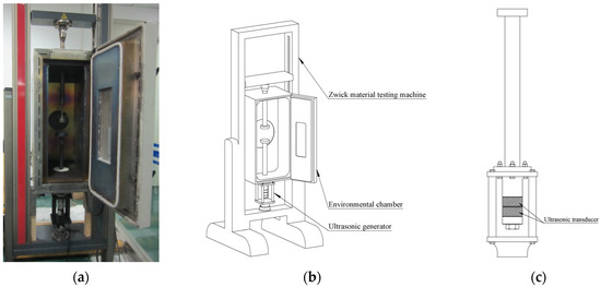
Figure 1.
Experimental scheme: (a) Test setup; (b) 3D model of test setup; (c) Ultrasonic generator.
The experimental material was Zr55Cu30Al10Ni5 bulk amorphous alloy, with a glass transition temperature of 420 °C and a crystallization onset temperature of 501 °C [20]. The alloy was first fabricated into rods with a diameter of 3 mm via copper mold suction casting. These rods were subsequently machined into cylindrical specimens of ϕ2.8 mm × 2.6 mm, and both end faces were carefully polished to ensure surface parallelism.
Uniaxial compression experiments were conducted on the specimens under quasi-static loading conditions using the ultrasonic vibration-assisted amorphous alloy thermoplastic forming setup. The top platen was loaded at a constant speed of 10 µm/s, and the experiments were performed at a temperature of 452 °C. Prior to testing, lubricant was applied to both ends of each specimen, which was then positioned centrally on the bottom platen. The specimen was heated to the target temperature and held for 1 min to ensure thermal equilibrium before deformation. After reaching a predetermined preload, ultrasonic vibration was activated and maintained until the specified ultimate load was achieved. Subsequently, the test was terminated, and the specimen was removed. The entire experimental process was completed within 7 min to prevent crystallization of the amorphous alloy. Detailed experimental parameters are summarized in Table 1.

Table 1.
Materials and experimental parameters.
The deformed specimens were examined using a deep-focus microscope to analyze morphological changes, followed by X-ray diffraction (XRD) analysis to confirm the preservation of the amorphous phase structure. Prior to testing, the specimen surfaces were polished to ensure surface integrity. XRD analysis was performed using a Shimadzu XRD-7000S (SHIMADZU, Kyoto City, Japan) X-ray diffractometer, with a scanning range of 20° to 80° and a scan rate of 0.5° per minute. The complete experimental procedure is illustrated in Figure 2.
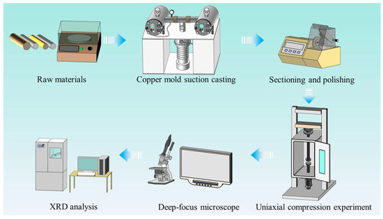
Figure 2.
Schematic of the experimental procedure.
To investigate the evolution of stress and strain during the ultrasonic vibration-assisted process, finite element simulations of the compression behavior of bulk amorphous alloys under various vibration amplitudes were conducted using ABAQUS (Abaqus CAE 2019). The material was modeled as elastic–plastic, with the constitutive relationship defined by experimentally obtained stress–strain curves at different strain rates from uniaxial compression tests. Axisymmetric elements were employed to improve computational efficiency without compromising accuracy. Ultrasonic vibration was applied to the lower platen, at a frequency of 20 kHz and an amplitude of 4.5 µm, the time-dependent displacement of the lower platen was expressed as . Differentiating this expression with respect to time yielded the velocity function . In Abaqus, ultrasonic vibration boundary conditions of lower platen were implemented through a periodic amplitude profile of the velocity function in the Amplitude module, and the velocity of upper platen was set to 10 µm/s.
3. Results
After the compression experiments, specimens deformed under different ultrasonic vibration frequencies and amplitudes, but at the same temperature, ultimate load, and loading speed were obtained, as shown in Figure 3. Under constant ultimate load conditions, the diameter of the deformed specimen serves as an indicator of its superplastic forming capability [21]. The measured diameters without vibration and under various vibration parameters are summarized in Table 2. Upon application of ultrasonic excitation, the diameters of all deformed specimens increased significantly. At an input amplitude of 9 µm, the deformation diameter increased from 3.80 mm to 4.24 mm, representing an 11% increase compared to the non-vibration condition. This demonstrates that ultrasonic vibration effectively enhances the superplastic flow and formability of amorphous alloys. The deformation diameter exhibits a clear dependence on vibration amplitude, increasing with higher input amplitudes, whereas the influence of frequency is less pronounced.

Figure 3.
Specimens after deformation: (a) f = 19 kHz; (b) f = 20 kHz.

Table 2.
Diameter of specimens after deformation.
The true stress–strain curve of the Zr55Cu30Al10Ni5 bulk amorphous alloy under compressive deformation can be derived from the experimental load–displacement data, as shown in Figure 4. The black curve represents the true stress–strain behavior without ultrasonic vibration (UV). When the true strain reaches 0.1, the material transitions from the elastic deformation stage to the steady-state rheological stage, and no stress overshoot is observed—this absence is attributed to the relatively high deformation temperature. Compared with constant strain rate conditions, the true stress–strain curve obtained under constant compression speed exhibits an upward trend due to non-uniform strain distribution. Upon application of ultrasonic vibration, the sample is no longer subjected to pure uniaxial compression; the introduction of ultrasonic energy reduces the flow stress of the amorphous alloy, leading to a phenomenon known as vibration-induced softening. Nevertheless, the overall trend of the curve remains consistent with that under constant load conditions, and neither stress overshoot nor stress undershoot—typically associated with rapid strain rate changes—is induced [22]. The sample avoids localized shear fracture and sustains uniform plastic deformation, which is attributed to the high-frequency, low-amplitude nature of ultrasonic vibration.
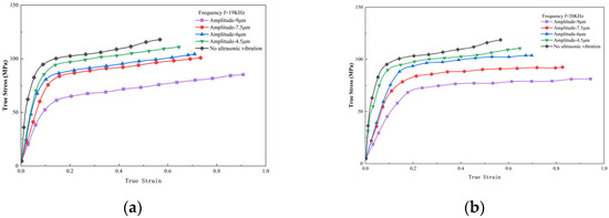
Figure 4.
True stress–strain curves of Zr55Cu30Al10Ni5 bulk amorphous alloy under different ultrasonic amplitudes and frequencies: (a) f = 19 kHz; (b) f = 20 kHz.
Figure 5 presents the rheological stress curves as a function of vibration frequency and amplitude. Since the strain rate varies during deformation, the true stress values at a true strain of 0.4 are selected for comparison. As shown in the figure, the vibration-induced softening effect exhibits a pronounced dependence on vibration amplitude. With increasing amplitude, the rheological stress decreases significantly; specifically, when the amplitude reaches 9 μm, the stress is reduced by approximately 30% relative to the constant load condition. In contrast, the influence of frequency on rheological stress is less evident, which may be attributed to the limited range of frequency variation in the experiments.
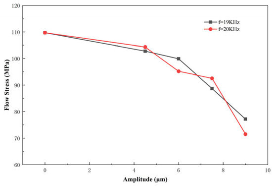
Figure 5.
Rheological stress curves as a function of vibration amplitudes and frequencies.
The two specimens exhibiting the longest deformation duration and largest deformation extent were selected for XRD analysis, along with a specimen deformed without vibration. These correspond to specimens subjected to vibration parameters of f = 20 kHz, a = 90% (9 µm) and f = 19 kHz, a = 90% (9 µm), respectively. As shown in Figure 6, the XRD patterns of all three specimens display distinct diffuse amorphous halos and absence of sharp Bragg diffraction peaks associated with crystalline grains, indicating that the samples retain a fully amorphous structure after deformation. The amorphous envelopes in the diffraction patterns are consistently located at 2θ = 38°, demonstrating that ultrasonic vibration does not induce significant alterations to the amorphous phase structure.
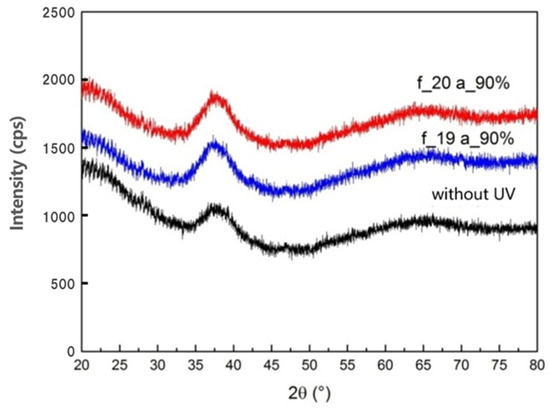
Figure 6.
XRD pattern of deformed specimens.
4. Discussion
The reduction in flow stress during plastic deformation of metals induced by ultrasonic vibration is generally attributed to two primary mechanisms: the volume effect and the surface effect. The volume effect involves two aspects: thermal softening resulting from the absorption of ultrasonic energy during metal forming, and stress superposition based on phenomenological mechanical principles. The surface effect refers to the influence of ultrasonic vibration on the frictional interaction between the specimen and the die. Unlike crystalline materials, amorphous alloys possess a homogeneous structure devoid of grain boundaries and dislocations—key sites for ultrasonic energy dissipation. As reported in literature [23], high-frequency vibrations exceeding 300 kHz can disrupt the glassy structure of amorphous alloys, whereas low-frequency vibrations do not produce such effects, suggesting that amorphous alloys exhibit negligible absorption of low-frequency ultrasound. Therefore, this study primarily focuses on the stress superposition and surface effects induced by ultrasonic vibration. Finite element simulations are employed to effectively capture the evolution of the stress–strain field and interfacial friction forces.
The compression processes without ultrasonic vibration and with different ultrasonic amplitudes were simulated and analyzed separately. The simulated load–displacement curves were compared with experimental data, as shown in Figure 7. In the absence of ultrasonic vibration, the simulation results closely matched the experimental data, validating the rationality of the numerical model. When an ultrasonic vibration with an amplitude of 4.5 µm was applied, the reaction force on the upper platen extracted from Abaqus exhibited an oscillating sawtooth pattern. By taking the peak values for curve fitting, the simulation still captured a trend consistent with the experimental results.
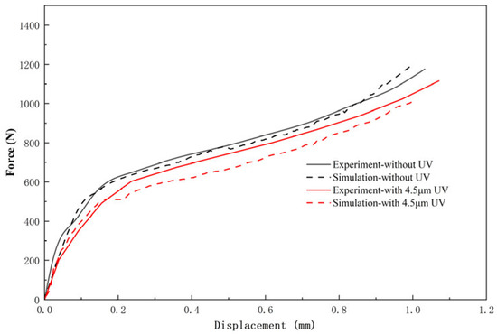
Figure 7.
Comparison of experimental and simulated load–displacement curves.
Figure 8a shows the stress distribution contour of the deformed specimen at a true strain of 0.4 without vibration, where the specimen has already reached the steady-state flow stage. A friction coefficient of 0.3 is applied between the pressure plates and the specimen. The specimen exhibits a typical symmetric drum-shaped profile, induced by interfacial friction between the specimen and the pressure plates. The magnitude of the friction force directly influences the radius of the top and bottom surfaces after deformation. After applying ultrasonic vibration with an amplitude of 4.5 µm, the deformation pattern changes, as shown in Figure 8b. Notably, the specimen no longer maintains a symmetric shape. The radius of the bottom surface (1.78 mm) exceeds that of the top surface (1.60 mm) and also surpasses the radius observed without vibration (1.55 mm), indicating that ultrasonic vibration reduces friction, with a more pronounced effect on the bottom interface, resulting in lower friction force there compared to the top. A similar deformation asymmetry is observed when the friction coefficients are reduced, as illustrated in Figure 8c.
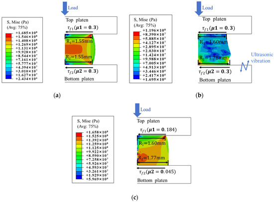
Figure 8.
Stress distribution contour after deformation: (a) Without vibration. (b) With 4.5 µm ultrasonic vibration. (c) With lower coefficient of friction.
The friction force curves on the top and bottom surfaces of the specimen during the deformation process are extracted and presented in Figure 9. Without ultrasonic vibration, the friction forces on both surfaces are equal and remain approximately constant at around 250 N after reaching the steady-state rheological stage. Upon application of ultrasonic vibration, the friction forces exhibit an oscillating sawtooth pattern, with peak amplitudes significantly lower than those observed without vibration. Specifically, the peak friction force on the top surface is approximately 200 N, representing a reduction of about 20%, while that on the bottom surface is approximately 50 N, corresponding to a reduction of nearly 80%.
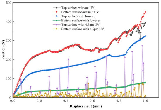
Figure 9.
Friction force curves on the upper and lower surfaces of the specimen.
In the process of ultrasonic vibration-assisted compression, the displacement–time curves of the top and bottom pressing plates are shown in Figure 10. Since the peak ultrasonic velocity of the lower pressing plate reaches 5.65 × 105 µm/s, far exceeding the top pressing plate’s speed of 10 µm/s, the distance between the two plates decreases only during approximately the first quarter of each ultrasonic vibration period, during which compressive deformation of the specimen occurs, and its height reduces from the initial value H0 to Hmin. For the remainder of the period, the distance between the plates exceeds Hmin, leading to separation between the pressing plates and the specimen, thereby causing intermittent friction loss. This friction force is generated and dissipated periodically, and, on a macroscopic level, it manifests as improved friction conditions.
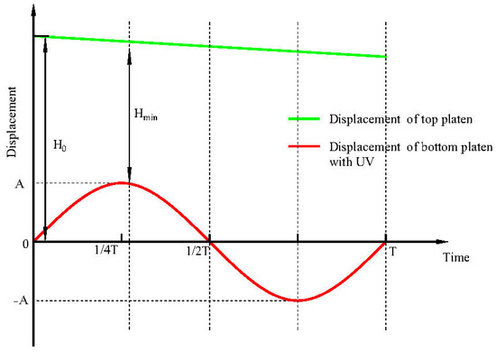
Figure 10.
Displacement–time curve of top and bottom pressure plates.
Figure 11 shows the surface morphology of the deformed specimens. Under the constant load mode, the specimen surface accurately replicates the surface topography of the die. After applying ultrasonic vibration, the surface quality deteriorates significantly, with large concave pits forming on the specimen surface. Figure 12 presents the three-dimensional surface morphology reconstructed by a deep-focus microscope. In the constant load mode, the specimen surface is smooth. With small vibration amplitudes, localized concavity appears on the surface while the edges remain smooth. At high amplitudes, even the edges become uneven and lose their smoothness. Traditionally, it has been believed that the surface effect of ultrasonic vibration improves the surface quality of formed parts. However, the findings of this study contradict this conventional view. The discrepancy arises because previous studies were primarily based on cold forming processes of solid metals, whereas in the case of amorphous alloy forming in the supercooled liquid region, the material viscosity is significantly lower than that of solid metals. Ultrasonic vibration induces intermittent separation at the interface between the specimen and the die, followed by repeated impact of the die on the specimen surface. In solid metal forming, this can promote lubricant infiltration and enhance surface finish. In contrast, for amorphous supercooled liquid, the extremely low viscosity and the potential for viscous welding lead to surface damage rather than improvement. The observed concave pits may result from air entrapment during interfacial separation.
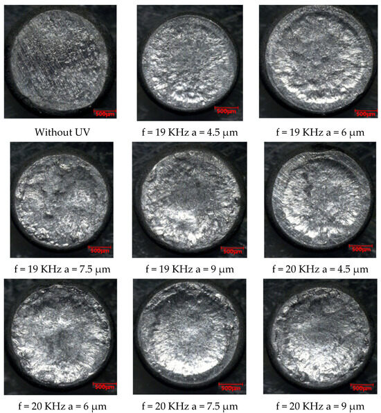
Figure 11.
Surface morphology of the specimens after deformation.
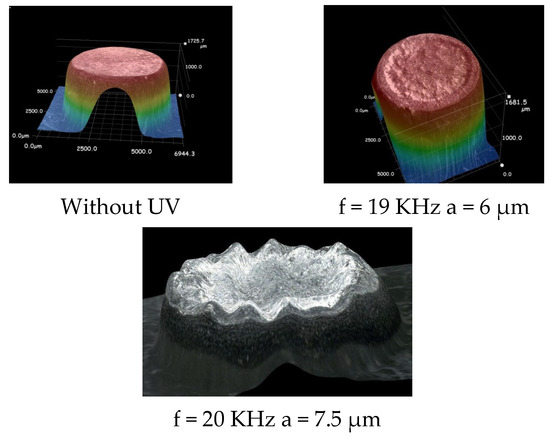
Figure 12.
Surface morphology by deep-focus microscope.
To eliminate the influence of surface effects and investigate stress superposition during the ultrasonic vibration process, a frictionless contact condition was applied between the specimen and the pressure plate in the simulation analysis. The stress and strain distributions are shown in Figure 13.
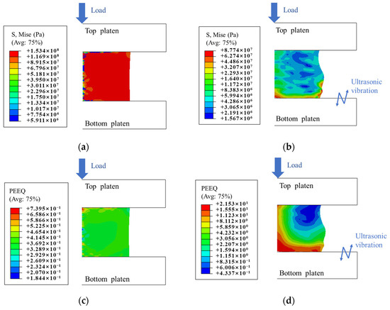
Figure 13.
Stress and strain distribution contour without friction: (a) Stress distribution contour without UV. (b) Stress distribution contour with 4.5 µm UV. (c) Strain distribution contour without UV. (d) Strain distribution contour with 4.5 µm UV.
When no vibration was applied, in the absence of friction, the specimen exhibited an ideal state of uniform deformation, with stress and strain evenly distributed. After applying ultrasonic vibration, the stress distribution became non-uniform. Since the vibration was applied to the bottom plate, stress concentration occurred at the bottom of the specimen. Stress data along the horizontal and vertical centerlines of the specimen were extracted, as shown in Figure 14a. Ultrasonic vibration resulted in a significant reduction in the Mise stress within the specimen, which explains the observed decrease in deformation load. From the equivalent plastic strain distribution, it can be observed that strain concentration developed at both the bottom and the center of the specimen after ultrasonic vibration was applied. Due to this non-uniform strain distribution, the specimen shape became distorted. Strain data along the same centerlines were also extracted, as shown in Figure 14b. Ultrasonic vibration was observed to increase plastic strain in strain-concentrated regions such as the specimen bottom and central axis, with the maximum plastic strain reaching 40.4 times the value observed without vibration.
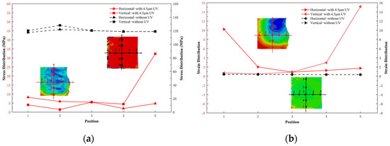
Figure 14.
Comparison of Stress and Strain: (a) Stress comparison. (b) Strain comparison.
The strain rate data was derived from the plastic strain. As illustrated in Figure 15, the application of ultrasonic vibration leads to a general increase in strain rate by more than a factor of two. At localized regions such as the specimen’s bottom and center areas, the enhancement can reach up to 40-fold.
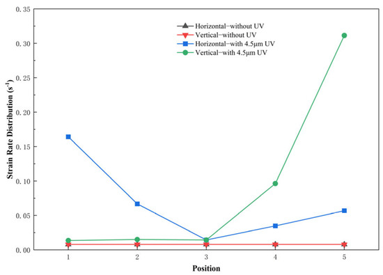
Figure 15.
Comparison of strain rate.
According to previous studies, supercooled liquid of amorphous alloys exhibits non-Newtonian fluid behavior at high strain rates, characterized by a stress sensitivity coefficient m < 1 and shear-thinning characteristics, wherein the material’s viscosity decreases with increasing of strain rate.
Assuming that the amorphous alloy undergoes viscous flow during rheological deformation in the supercooled liquid region—characterized by a Reynolds number approximately zero and no-slip boundary conditions at the flow channel interface—the micro-forming capability of the alloy under these conditions can be described by the Hagen–Poiseuille equation:
p = 32vηL/d2,
Here, p denotes the pressure required for a fluid with rheological viscosity η to flow at velocity v through a channel of thickness d and length L. The maximum processing time of amorphous alloys is governed by their crystallization kinetics and is denoted as tmax. Substituting v = L/tmax into Equation (1) yields the maximum filling length [18]:
As indicated by Equation (2), reducing the apparent viscosity at a given temperature can improve the formability of amorphous alloys. The apparent viscosity of the supercooled liquid state of amorphous alloys is:
In the equation, σ denotes the flow stress and represents the strain rate. During the compression process, experimental data of rheological stress and strain rate at a true strain of 0.4 were used to calculate apparent viscosity. The calculated results are presented in Figure 16.
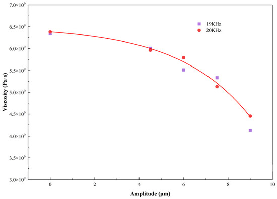
Figure 16.
Viscosity as a function of input amplitudes and frequencies.
As shown in Figure 16, ultrasonic vibration reduces the apparent viscosity of the supercooled liquid of amorphous alloys, thereby improving their superplastic formability. At a fixed frequency, the viscosity decreases exponentially with increasing input amplitude. Based on experimental data, the empirical relationship between viscosity η and input amplitude A is fitted as η = 6.511 × 10⁹–1.265 × 10⁸ e0.311a. In contrast, viscosity exhibits negligible variation with frequency.
5. Conclusions
This study introduces ultrasonic vibration into the superplastic flow forming process of amorphous alloys, designs an experimental setup for ultrasonic vibration-assisted thermoplastic forming, conducts compression deformation experiments, and performs numerical simulations to analyze the deformation behavior, leading to the following conclusions:
- (1)
- The experimental results demonstrate that applying ultrasonic vibration during the deformation of amorphous alloys leads to a reduction in rheological stress with increasing input amplitude. At an amplitude of 9 μm, the rheological stress is reduced by 30% relative to the conventional loading condition. Under an ultimate load of 1300 N, the maximum sample deformation increases by 11%, confirming that ultrasonic vibration assistance enhances the superplastic formability of amorphous alloys.
- (2)
- The finite element simulation results indicate that ultrasonic vibration induces periodic separation at the interface between the pressure plate and the sample, leading to a corresponding periodic disappearance of friction force. Macroscopically, this manifests as a reduction in effective friction. However, due to the low viscosity of the supercooled liquid and the occurrence of viscous welding, the vibration adversely affects the surface morphology of the sample, thereby degrading its surface quality.
- (3)
- Ultrasonic vibration leads to a significant reduction in the principal stress and an increase in plastic strain within the sample. Given that the supercooled liquid of amorphous alloys exhibits non-Newtonian fluid behavior, the introduction of ultrasonic vibration generates an additional strain rate, which reduces the material’s viscosity and consequently enhances its filling capability. An empirical relationship describing the apparent viscosity as a function of amplitude is expressed as η = 6.511 × 10⁹–1.265 × 10⁸ e0.311a.
This study provides novel insights and effective methodologies for the development of superplastic forming processes of amorphous alloys while establishing a robust theoretical foundation to support the expansion of their industrial applications.
Author Contributions
Conceptualization, H.L.; methodology, H.L.; software, H.L.; validation, H.L. and C.S.; formal analysis, H.L. and C.S.; investigation, H.L. and C.S.; resources, H.L. and C.S.; data curation, H.L.; writing—original draft preparation, H.L.; writing—review and editing, J.L. and C.L.; visualization, C.L.; supervision, J.L. and C.L.; project administration, J.L. and C.L.; funding acquisition, J.L. and H.L. All authors have read and agreed to the published version of the manuscript.
Funding
This research was funded by Natural Science Foundation of Jiangsu Province, grant number BK20220241, 2024 Jiangsu Provincial “Qinglan Project” Outstanding Young Key Teacher Program, Jiangsu Higher Education Teaching Reform Research Project grant number 2025JGYB033, Changzhou Applied Basic Research Program, grant number CJ20220181, and Research Project on Higher Vocational Education of Changzhou University, grant number CDGZ202530.
Data Availability Statement
The original contributions presented in this study are included in the article. Further inquiries can be directed to the corresponding author.
Acknowledgments
We thank Canhua Li for his technical support and helpful discussions. We also acknowledge Changzhou Vocational Institute of Industry Technology for its financial support. Finally, we appreciate the constructive comments from colleagues during the preparation of this manuscript.
Conflicts of Interest
The authors declare no conflicts of interest.
References
- Sohrabi, S.; Fu, J.N.; Li, L.Y.; Zhang, Y.; Li, X.; Sun, F.; Ma, J.; Wang, W.H. Manufacturing of Metallic Glass Components: Processes, Structures and Properties. Prog. Mater. Sci. 2024, 144, 101283. [Google Scholar] [CrossRef]
- Schroers, J. Processing of Bulk Metallic Glass. Adv. Mater. 2010, 22, 1566–1597. [Google Scholar] [CrossRef]
- Najgebauer, M.; Chwastek, K.; Szczyglowski, J. Energy Efficient Distribution Transformers. Prz. Elektrotechniczny 2011, 2, 111–114. [Google Scholar]
- He, F.; Zhi, J.Y.; He, Z.J.; Tian, Y.L.; Zhao, Z.Y.; Xie, J.L. Preparation of Low Thermal Expansion Transparent LAS Glass-ceramics via Simplified Heat-treatment Method. Ceram. Int. 2024, 50, 41654–41663. [Google Scholar] [CrossRef]
- Kim, W.J.; Ma, D.S.; Jeong, H.G. Superplastic Flow in a Zr65Al10Ni10Cu15 Metallic Glass Crystallized during Deformation in a Supercooled Liquid Region. Scr. Mater. 2003, 49, 1067–1073. [Google Scholar] [CrossRef]
- Wang, G.; Shen, J.; Sun, J.F.; Huang, Y.J.; Zou, J.; Lu, Z.P.; Stachurski, Z.H.; Zhou, B.D. Super Plasticity and Superplastic Forming Ability of a Zr-Ti-Ni-Cu-Be Bulk Metallic Glass in the Supercooled Liquid Region. J. Non-Cryst. Solids 2005, 351, 209–217. [Google Scholar] [CrossRef]
- Gong, P.; Wang, S.B.; Liu, Z.; Chen, W.; Li, N.; Wang, X.Y.; Yao, K.F. Lightweight Ti-Based Bulk Metallic Glasses with Superior Thermo plastic Formability. Intermetallics 2018, 98, 54–59. [Google Scholar] [CrossRef]
- Song, S.M.; Liao, Y.C.; Li, T.H.; Lee, C.K.; Tasi, P.H.; Jang, J.S.C.; Huang, J.C. Thermoplastic Deformation Behavior of a Fe-Based Bulk Metallic Glass within the Supercooled Liquid Region. J. Mater. Res. Technol. 2019, 8, 1907–1914. [Google Scholar] [CrossRef]
- Savaedi, Z.; Motallebi, R.; Mirzadeh, H.; Malekan, M. Superplasticity of Bulk Metallic Glasses (BMGs): A review. J. Non-Cryst. Solids 2022, 583, 121503. [Google Scholar] [CrossRef]
- Liu, S.S.; Hou, C.N.; Wang, E.G.; Peng, J. Plastic Rheological Behaviors of Zr61Cu25Al12Ti2 and Zr52.5Cu17.9Ni14.6Al10Ti5 Amorphous Alloys in the Supercooled Liquid Region. Acta Metall. Sin. 2022, 58, 807–815. [Google Scholar]
- Yang, K.; Fan, X.H.; Li, B.; Li, Y.L.; Wang, X. Optimisation of Superplastic Processing Parameters for a TiZrHfBeCuNi High Entropy Bulk Metallic Glass in the Supercooled Liquid Region. J. Mater. Res. Technol. 2022, 24, 1911–1921. [Google Scholar] [CrossRef]
- Li, J.L.; Li, C.Y.; Wang, S.P.; Wang, H.B.; Kou, S.Z. Thermal Processing Map and Thermoplastic Forming Map of Zr-Based Bulk Metallic Glass in the Super cooled Liquid Region. J. Non-Cryst. Solids 2021, 570, 121008. [Google Scholar] [CrossRef]
- Lou, Y.; He, J.S.; Chen, H.; Long, M. Effects of Vibration Amplitude and Relative Grain Size on the Rheological Behavior of Copper during Ultrasonic-assisted Microextrusion. Int. J. Adv. Manuf. Technol. 2017, 89, 2421–2433. [Google Scholar] [CrossRef]
- Xie, Z.D.; Guan, Y.J.; Zhu, L.H.; Zhai, J.Q.; Lin, J.; Yu, X.H. Investigations on the Surface Effect of Ultrasonic Vibration-assisted 6063 Aluminum Alloy Ring Upsetting. Int. J. Adv. Manuf. Technol. 2018, 96, 4407–4421. [Google Scholar] [CrossRef]
- Xie, Z.D.; Guan, Y.J.; Zhu, L.H.; Zhai, J.Q.; Lin, J.; Yu, X.H. Constitutive Model of 6063 Aluminum Alloy under the Ultrasonic Vibration Upsetting Based on Johnson-Cook Model. Ultrasonics 2019, 96, 1–9. [Google Scholar] [CrossRef]
- Wan, W.Q.; Ying, Z.D.; Han, G.C.; Yang, M.; Hu, J.T.; Liu, F.C.; Xun, L.H.; Bai, W.; Chen, H. Mechanical Properties and Microstructure Evolution of T2 Copper in Multimodal Ultrasonic Vibration Assisted Micro-compression. J. Mater. Sci. Technol. 2025, 208, 152–163. [Google Scholar] [CrossRef]
- Wan, W.Q.; Han, G.C.; Liu, F.C.; Yang, M.; Hu, J.T.; Liu, F.C.; Xun, L.H.; Bai, W.; Chen, H. Surface and Volume Effects in Multimodal Ultrasonic Vibration Assisted Micro-extrusion Forming: Experiments and Modelling. J. Mater. Process. Technol. 2023, 322, 118185. [Google Scholar] [CrossRef]
- Han, G.C.; Wan, W.Q.; Zhang, Z.C.; Xu, L.H.; Liu, F.C.; Zhang, H.O. Experimental Investigation into Effects of Different Ultrasonic Vibration Modes in Micro-extrusion Process. J. Manuf. Process. 2021, 67, 427–437. [Google Scholar] [CrossRef]
- Zhang, H.D.; Deng, L.; Hao, Y.; Li, C.; Tang, X.F.; Gong, P.; Zhang, M.; Jin, J.S.; Wang, X.Y. Anisotropic and Heterogeneous Acoustoplasticity of α-Ti during Ultrasonic Vibration Assisted Compression: Modeling and Experiments. Int. J. Plast. 2024, 173, 103886. [Google Scholar] [CrossRef]
- Wu, X.; Li, J.J.; Zheng, Z.Z.; Liu, L.; Li, L. Micro-back-extrusion of a Bulk Metallic Glass. Scr. Mater. 2010, 63, 469–472. [Google Scholar] [CrossRef]
- Schroers, J. On the Formability of Bulk Metallic Glass in Its Supercooled Liquid State. Acta Mater. 2008, 56, 471–478. [Google Scholar] [CrossRef]
- Lu, J.; Ravichandran, G.; Johnson, W.L. Deformation Behavior of the Zr41.2Ti13.8Cu12.5Ni10Be22.5 Bulk Metallic Glass ver a Wide Range of Strain-rates and Temperatures. Acta Mater. 2003, 51, 3429–3443. [Google Scholar] [CrossRef]
- Ichitsubo, T.; Kai, S.; Ogi, H.; Hiraoet, M.; Tanaka, K. Elastic and Anelastic Behavior of Zr55Al10Ni5Cu30 Bulk Metallic Glass around the Glass Transition Temperature under Ultrasonic Excitation. Scr. Mater. 2003, 49, 267–271. [Google Scholar] [CrossRef]
Disclaimer/Publisher’s Note: The statements, opinions and data contained in all publications are solely those of the individual author(s) and contributor(s) and not of MDPI and/or the editor(s). MDPI and/or the editor(s) disclaim responsibility for any injury to people or property resulting from any ideas, methods, instructions or products referred to in the content. |
© 2025 by the authors. Licensee MDPI, Basel, Switzerland. This article is an open access article distributed under the terms and conditions of the Creative Commons Attribution (CC BY) license (https://creativecommons.org/licenses/by/4.0/).